

Page 1

INSTRUCTIONS
ENDOSCOPE REPROCESSOR
OER-Elite¥
Labels and Symbols 1
Important Information — Please Read Before
Use 7
Chapter 1 Checking the Package Contents 19
Chapter 2 Nomenclature and Functions 23
Chapter 3 Basic Operation 35
Chapter 4 Settings 75
Chapter 5 Inspection and Preparation
Before Use 127
Chapter 6 Reprocessing Operations 147
Chapter 7 Functions 239
Chapter 8 Replacement of Consumable
Items 339
Chapter 9 Routine Maintenance 423
Chapter 10 End-of-Day Checks 451
Chapter 11 Log Management 463
Chapter 12 Information Menu Screen 589
Chapter 13 Troubleshooting and Repair 599
Appendix 647
For details on installation and setup, refer to “Instructions - Installation Manual”.
OPERATION MANUAL
Page 2

Page 3

Contents
i
OER-Elite OPERATION MANUAL
Contents
Labels and Symbols .......................................................................................................... 1
Important Information — Please Read Before Use ......................................................... 7
Intended use .......................................................................................................................... 7
Instruction manuals ............................................................................................................... 7
Terms used in these manuals ................................................................................................ 8
User qualifications ................................................................................................................ 11
Ensuring the safety of reprocessing personnel ................................................................... 12
Equipment compatibility ....................................................................................................... 13
Care and storage ................................................................................................................. 13
Maintenance and Inspection ................................................................................................ 13
Repair and modification ....................................................................................................... 13
Disposal of disinfectant solution .......................................................................................... 14
Disposal of this reprocessor ................................................................................................ 14
Signal words ........................................................................................................................ 14
Warnings and cautions ........................................................................................................ 14
Outline of Functions ........................................................................................................ 16
Chapter 1 Checking the Package Contents ....................................... 19
1.1 Checking the package contents ............................................................................ 19
Chapter 2 Nomenclature and Functions ............................................ 23
2.1 Front panel .............................................................................................................. 23
2.2 Top panel ................................................................................................................. 24
2.3 Inside ....................................................................................................................... 25
2.4 Rear panel ............................................................................................................... 26
2.5 Side panel ................................................................................................................ 27
2.6 Reprocessing basin ............................................................................................... 28
2.7 Control panels ........................................................................................................ 30
2.8 Consumable accessories (Optional) .................................................................... 31
Chapter 3 Basic Operation .................................................................. 35
3.1 Turning power ON .................................................................................................. 35
3.2 Alarm indicator ....................................................................................................... 37
3.3 Control panel operation ......................................................................................... 40
3.4 Menu screen ........................................................................................................... 41
3.5 LCG Info. screen ..................................................................................................... 42
Page 4

ii
Contents
OER-Elite OPERATION MANUAL
3.6 Entering ID .............................................................................................................. 44
Entering through the RFID reader ....................................................................................... 45
Entering by the software keyboard ...................................................................................... 48
Entering the patient ID by the optional bar code ................................................................. 65
3.7 Checking the MRC level and entering the check result ...................................... 69
Required items .................................................................................................................... 70
Checking the MRC level ...................................................................................................... 70
Chapter 4 Settings ................................................................................ 75
4.1 Setting menu ........................................................................................................... 75
4.2 Auto leak test setting ............................................................................................. 79
4.3 MRC check setting ................................................................................................. 81
4.4 Manual cleaning and leak test setting .................................................................. 82
4.5 User ID Setting ........................................................................................................ 83
User ID setting (reprocessing) ............................................................................................. 84
User ID setting (functions and replacement) ....................................................................... 86
User ID setting (Heat LCG Timer) ....................................................................................... 87
4.6 Physician ID setting ............................................................................................... 88
4.7 Patient ID setting .................................................................................................... 89
4.8 Patient ID security setting ..................................................................................... 90
4.9 Procedure ID setting .............................................................................................. 91
4.10 Detergent replacement indicator .......................................................................... 92
4.11 Detergent lot number and shelf-life management ............................................... 94
4.12 LCG replacement indicator .................................................................................... 95
4.13 LCG lot number and shelf-life management ........................................................ 98
4.14 Filter replacement indicator .................................................................................. 99
4.15 Filter lot number management ............................................................................ 103
4.16 Auxiliary water tube cleaning setting ................................................................. 104
4.17 Print option ........................................................................................................... 106
Print format setting ............................................................................................................ 107
Auto Print Setting ............................................................................................................... 108
4.18 Start screen ........................................................................................................... 109
4.19 Connection guide ................................................................................................. 110
4.20 Volume and brightness ........................................................................................ 111
4.21 Date and time ........................................................................................................ 112
4.22 Temperature scale ................................................................................................ 115
4.23 Network setting ..................................................................................................... 116
4.24 Network security ................................................................................................... 121
Page 5

Contents
iii
OER-Elite OPERATION MANUAL
Chapter 5 Inspection and Preparation Before Use .......................... 127
5.1 Inspection before use .......................................................................................... 127
5.2 Flow of inspection ................................................................................................ 128
5.3 Inspecting the power activation .......................................................................... 129
5.4 Inspecting for fluid leaks ..................................................................................... 132
5.5 Inspecting the lid and lid packing ....................................................................... 133
5.6 Inspecting the connectors ................................................................................... 134
5.7 Inspecting the connecting tubes and leak test air tube ................................... 137
5.8 Inspecting the remaining detergent ................................................................... 138
5.9 Inspecting and replenishing alcohol .................................................................. 139
Inspection of the amount of alcohol ................................................................................... 140
Replenishing of alcohol ..................................................................................................... 140
5.10 Inspecting the mesh filters .................................................................................. 143
5.11 Inspecting the washing case (MAJ-2121) .......................................................... 144
5.12 Inspecting the labels on the reprocessing basin .............................................. 145
5.13 Inspecting for disinfectant solution odor ........................................................... 145
Chapter 6 Reprocessing Operations ................................................ 147
6.1 General flow of endoscope reprocessing using OER-Elite .............................. 147
6.2 Precleaning, leak testing, and manual cleaning ................................................ 148
Modified manual cleaning process for preparing endoscopes for processing in the
OER-Elite ........................................................................................................................... 149
Endoscope precleaning
(Procedure performed at bedside immediately after patient examination) ........................ 149
Endoscope precleaning continued
(Procedure performed at bedside immediately after patient examination) ........................ 150
Leakage testing ................................................................................................................. 152
Manual cleaning (procedure performed in reprocessing area) .......................................... 152
Loading the endoscope and their accessories into the OER-Elite .................................... 154
6.3 Reprocessing operation in the OER-Elite .......................................................... 155
Warnings ............................................................................................................................ 155
Outline of reprocessing operation in the OER-Elite ........................................................... 157
6.4 Worst case load condition of endoscopes and accessories ........................... 158
6.5 Basic operation for reprocessing ....................................................................... 160
Reprocessing standby screen ........................................................................................... 160
Reprocessing program ...................................................................................................... 162
Page 6

iv
Contents
OER-Elite OPERATION MANUAL
6.6 Loading of endoscopes and accessories .......................................................... 163
Outline of loading operation of endoscopes and accessories ........................................... 163
Input scope ID of first endoscope ...................................................................................... 165
Loading of first endoscopes in the reprocessing basin ...................................................... 166
Loading of the accessories of first endoscope (valves, etc.) ............................................. 173
Attaching the connecting tubes loading to first endoscope ............................................... 177
Loading of auxiliary water tube of first endoscope ............................................................ 186
Attaching the Leak test air tube loading to first endoscope ............................................... 189
Input connection information of first endoscope ................................................................ 194
Input results of manual cleaning and leak test of first endoscope ..................................... 195
Inputs user ID, physician ID, patient ID, and procedure ID of first endoscope .................. 196
Input scope ID of second endoscope ................................................................................ 197
Loading of second endoscopes in the reprocessing basin ................................................ 197
Loading of the accessories of second endoscope (valves, etc.) ....................................... 202
Attaching the connecting tubes loading to second endoscope .......................................... 205
Loading of auxiliary water tube of second endoscope ........................................................ 211
Attaching the Leak test air tube loading to second endoscope ......................................... 213
Input connection information of second endoscope .......................................................... 214
Input results of manual cleaning and leak test of second endoscope ............................... 214
Inputs user ID, physician ID, patient ID, and procedure ID of second endoscope ............ 214
Loading the stylus pen ....................................................................................................... 215
6.7 Inspection before starting reprocessing process ............................................. 216
6.8 Reprocessing ........................................................................................................ 220
Auto leak test ..................................................................................................................... 221
Channel monitoring ........................................................................................................... 223
Reprocessing operation ..................................................................................................... 225
6.9 Removing the endoscopes and accessories ..................................................... 228
6.10 Printing of the reprocessing records ................................................................. 232
Printing reprocessing results after completion of reprocessing ......................................... 234
Printing error code details in case of error ......................................................................... 237
Chapter 7 Functions ........................................................................... 239
7.1 Function menu ...................................................................................................... 239
Function menu ................................................................................................................... 239
7.2 Heat LCG ............................................................................................................... 242
7.3 Heat LCG Timer ..................................................................................................... 244
Flow of Heat LCG Timer .................................................................................................... 245
Starting the Heat LCG Timer ............................................................................................. 245
Standing by and starting the Heat LCG Timer ................................................................... 253
Finishing the Heat LCG Timer ........................................................................................... 254
7.4 Mix LCG ................................................................................................................. 255
7.5 Rinse ...................................................................................................................... 258
7.6 Air purge ................................................................................................................ 260
Page 7

Contents
v
OER-Elite OPERATION MANUAL
7.7 Water line disinfection ......................................................................................... 262
Workflow of water line disinfection ..................................................................................... 263
Required items .................................................................................................................. 264
Checking the MRC level and entering the check result ..................................................... 264
Water line disinfection ........................................................................................................ 266
7.8 Self-disinfection and water sampling ................................................................. 274
Workflow of self-disinfection .............................................................................................. 274
Required items .................................................................................................................. 275
Checking the MRC level and entering the check result ..................................................... 275
Performing the self-disinfection ......................................................................................... 277
Microbiological Surveillance .............................................................................................. 281
7.9 Detergent line disinfection .................................................................................. 282
Required items .................................................................................................................. 283
Detergent line disinfection ................................................................................................. 283
7.10 Alcohol line disinfection ...................................................................................... 293
Required items .................................................................................................................. 294
Alcohol line disinfection ..................................................................................................... 294
7.11 Manual leak test .................................................................................................... 303
Workflow of manual leak test ............................................................................................. 304
Performing manual leak test .............................................................................................. 305
7.12 Auto leak test ........................................................................................................ 310
Workflow of auto leak test .................................................................................................. 312
Performing auto leak test ................................................................................................... 313
7.13 Self-check of auto leak test ................................................................................. 321
7.14 Alcohol flush ......................................................................................................... 323
7.15 Leaking scope decontamination ......................................................................... 326
Workflow of leaking scope decontamination ...................................................................... 328
Required items .................................................................................................................. 328
Performing leaking scope decontamination ....................................................................... 329
Chapter 8 Replacement of Consumable Items ................................ 339
8.1 Replacement of consumable items menu .......................................................... 339
8.2 Replacing the disinfectant solution .................................................................... 340
Workflow of replacement the disinfectant solution ............................................................. 341
Draining the disinfectant solution ....................................................................................... 342
Load the disinfectant solution ............................................................................................ 354
Required items .................................................................................................................. 355
Setting the disinfectant solution ......................................................................................... 356
8.3 Replacing the detergent tank .............................................................................. 364
Required item .................................................................................................................... 365
Replacing the detergent tank ............................................................................................. 366
Page 8

vi
Contents
OER-Elite OPERATION MANUAL
8.4 Replacing the water filter (MAJ-824 or MAJ-2318) ............................................ 375
Replacing the water filter workflow (when performing the water line disinfection followed by the
replacement of the water filter) .......................................................................................... 377
Required items .................................................................................................................. 377
MRC check, check result input .......................................................................................... 378
Replacing the water filter ................................................................................................... 380
Draining air in the water filter housing ............................................................................... 389
Disinfecting the water line .................................................................................................. 392
8.5 Replacing the air filter (MAJ-823) ........................................................................ 402
Workflow of replacement of the air filter ............................................................................ 402
Required items .................................................................................................................. 402
Replacing the air filter ........................................................................................................ 403
Inspecting air leakage from the air filter connectors .......................................................... 408
8.6 Replacing the gas filter (MAJ-822) ...................................................................... 411
Required items .................................................................................................................. 412
Replacing the gas filter on the lid ...................................................................................... 412
Replacing the gas filter on the disinfectant solution tank ................................................... 416
Chapter 9 Routine Maintenance ........................................................ 423
9.1 Periodic inspection .............................................................................................. 423
9.2 Cleaning the detergent/alcohol drawer .............................................................. 425
9.3 Cleaning the accessories and accessory holder .............................................. 426
Required items .................................................................................................................. 426
Cleaning the accessories and accessory holder ............................................................... 426
9.4 Cleaning the alcohol tank .................................................................................... 428
9.5 Checking cassette cutters ................................................................................... 429
9.6 Cleaning the disinfectant bottle drawer ............................................................. 429
9.7 Cleaning the mesh filter in the water supply hose connector .......................... 430
Required items .................................................................................................................. 430
Cleaning the mesh filter in the water supply hose connector ............................................ 430
9.8 Replacing the fuse ................................................................................................ 434
9.9 Preparing the reprocessor for long-term storage ............................................. 436
Workflow of Preparing the reprocessor for long-term storage ........................................... 437
Required items .................................................................................................................. 437
Preparing the reprocessor for long-term storage ............................................................... 438
9.10 Care and maintenance after long-term storage ................................................. 448
Chapter 10 End-of-Day Checks ........................................................... 451
10.1 Inspection at the end of every working day ....................................................... 451
10.2 Turning the power OFF and closing the water faucet ....................................... 452
10.3 Cleaning the mesh filters ..................................................................................... 453
10.4 Cleaning the float switches ................................................................................. 454
10.5 Cleaning the fluid level sensor ............................................................................ 458
Page 9

Contents
vii
OER-Elite OPERATION MANUAL
10.6 Cleaning the stylus pen ....................................................................................... 460
Wiping the stylus pen with alcohol ..................................................................................... 460
Reprocessing together with endoscopes ........................................................................... 460
10.7 Cleaning the outer surface .................................................................................. 461
Chapter 11 Log Management .............................................................. 463
11.1 Log menu .............................................................................................................. 463
11.2 Log display and output ........................................................................................ 464
Information recorded in each record .................................................................................. 470
11.3 Log management with PC ................................................................................... 533
Flow of electronic log management ................................................................................... 534
Required item .................................................................................................................... 534
Output of recorded data to the portable memory ............................................................... 535
Log management on PC .................................................................................................... 541
11.4 Printing records .................................................................................................... 575
Printing .............................................................................................................................. 575
Print format ........................................................................................................................ 579
Chapter 12 Information Menu Screen ................................................. 589
12.1 RFID data check .................................................................................................... 589
12.2 Reprocessor information check ......................................................................... 592
12.3 List management .................................................................................................. 595
Chapter 13 Troubleshooting and Repair ............................................ 599
13.1 Emergency stop and automatic processing after stopping ............................. 599
13.2 Troubleshooting guide ......................................................................................... 600
When the error code [E024] is displayed during the reprocessing process ...................... 614
When any leaks are detected ............................................................................................ 617
When the message screen “Message 087” is displayed ................................................... 627
When the “Message 093” is displayed .............................................................................. 635
Other problems and remedial actions ................................................................................ 642
13.3 OER-Elite return ................................................................................................... 645
Appendix ............................................................................................... 647
System chart .................................................................................................................. 647
Specifications ................................................................................................................ 649
Shipping environment ........................................................................................................ 649
Operating environment ...................................................................................................... 649
Specifications ..................................................................................................................... 650
EMC information ............................................................................................................ 653
License information of Open Source Software ........................................................... 658
License information of Open Source Software ........................................................... 670
Page 10

viii
Contents
OER-Elite OPERATION MANUAL
Page 11
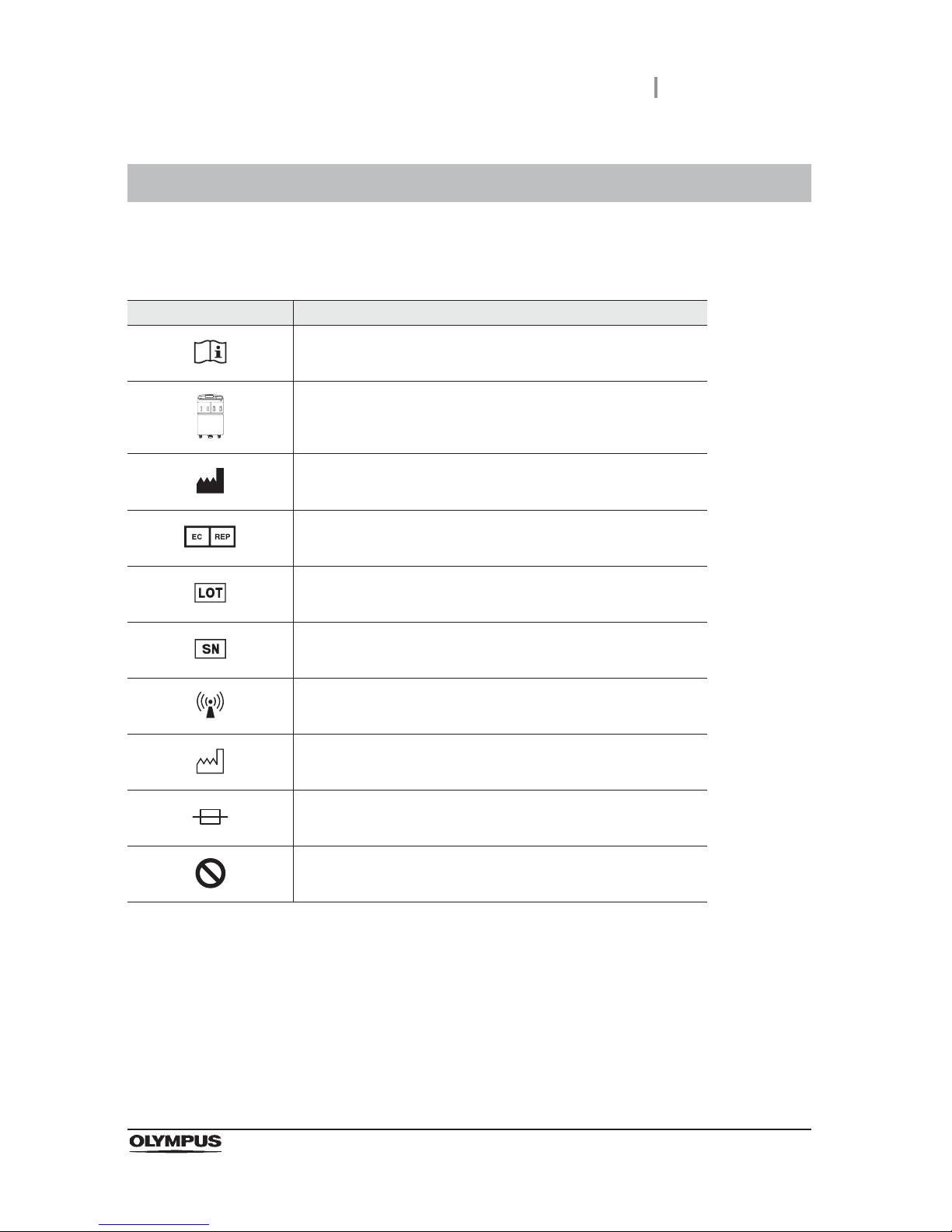
Labels and Symbols
1
OER-Elite OPERATION MANUAL
The meaning(s) of the symbol(s) shown on the component packaging, the back cover of this instruction
manual and/or this reprocessor are as follows:
For US Customers only
For a Symbols Glossary, visit us:
http://www.olympus-global.com/en/common/pdf/symbolsglossary.pdf
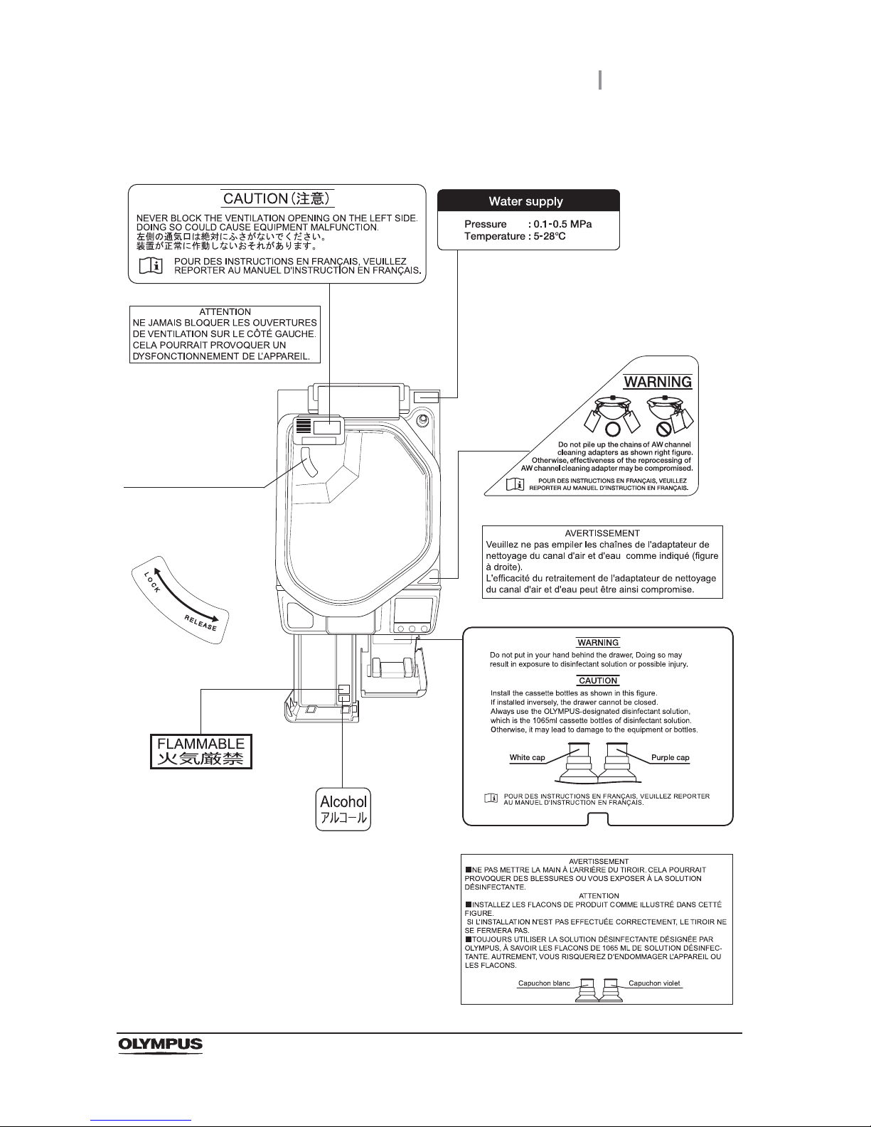
Safety-related labels and symbols are attached to the reprocessor at the locations shown next page. If
labels or symbols are missing or illegible, contact Olympus.
Labels and Symbols
Symbol Description
Refer to instructions.
Endoscope reprocessor
Manufacturer
Authorized representative in the European Community
Lot number
Serial number
Non-ionizing electromagnetic radiation
Date of manufacture
Fuse
General prohibition sign
Page 12
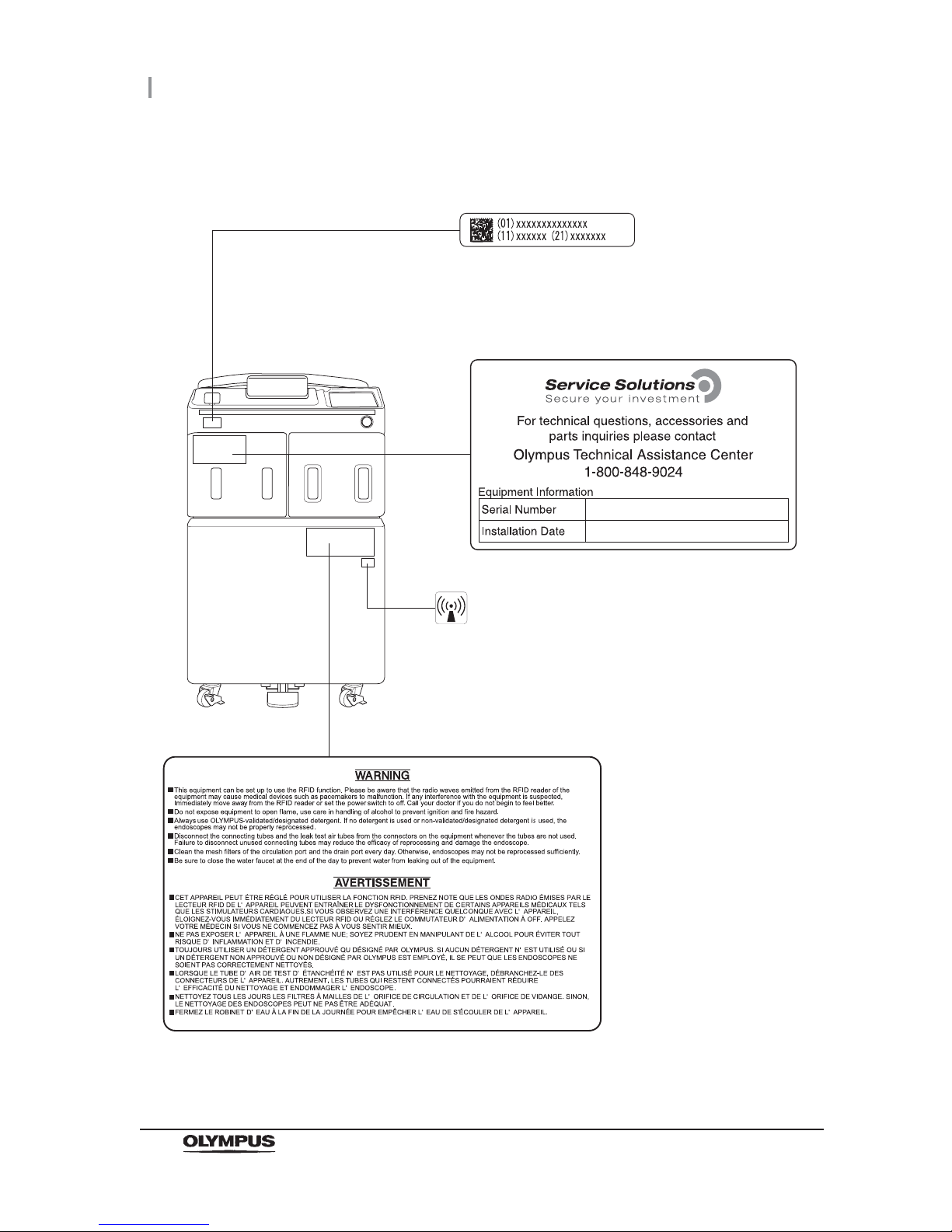
2
Labels and Symbols
OER-Elite OPERATION MANUAL
Front panel
RFID marking
UDI label
A label required by some countries’
regulations regarding identification of
medical device also known as Unique
Device Identification (UDI).
Page 13
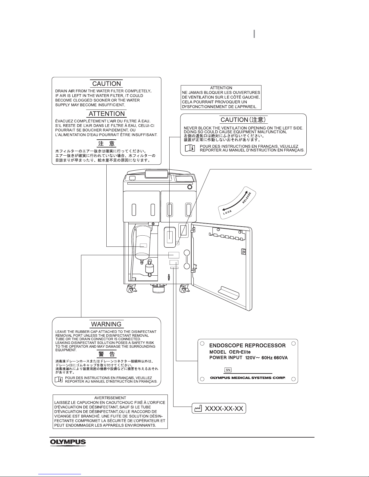
Labels and Symbols
3
OER-Elite OPERATION MANUAL
Inner side
Rotation direction indicator label
Indicates the rotation direction for locking
and releasing gas filter case (tank).
Rating plate
Shows the product model, power rating,
and serial number.
FRA
FRA
Date of manufacture
Page 14
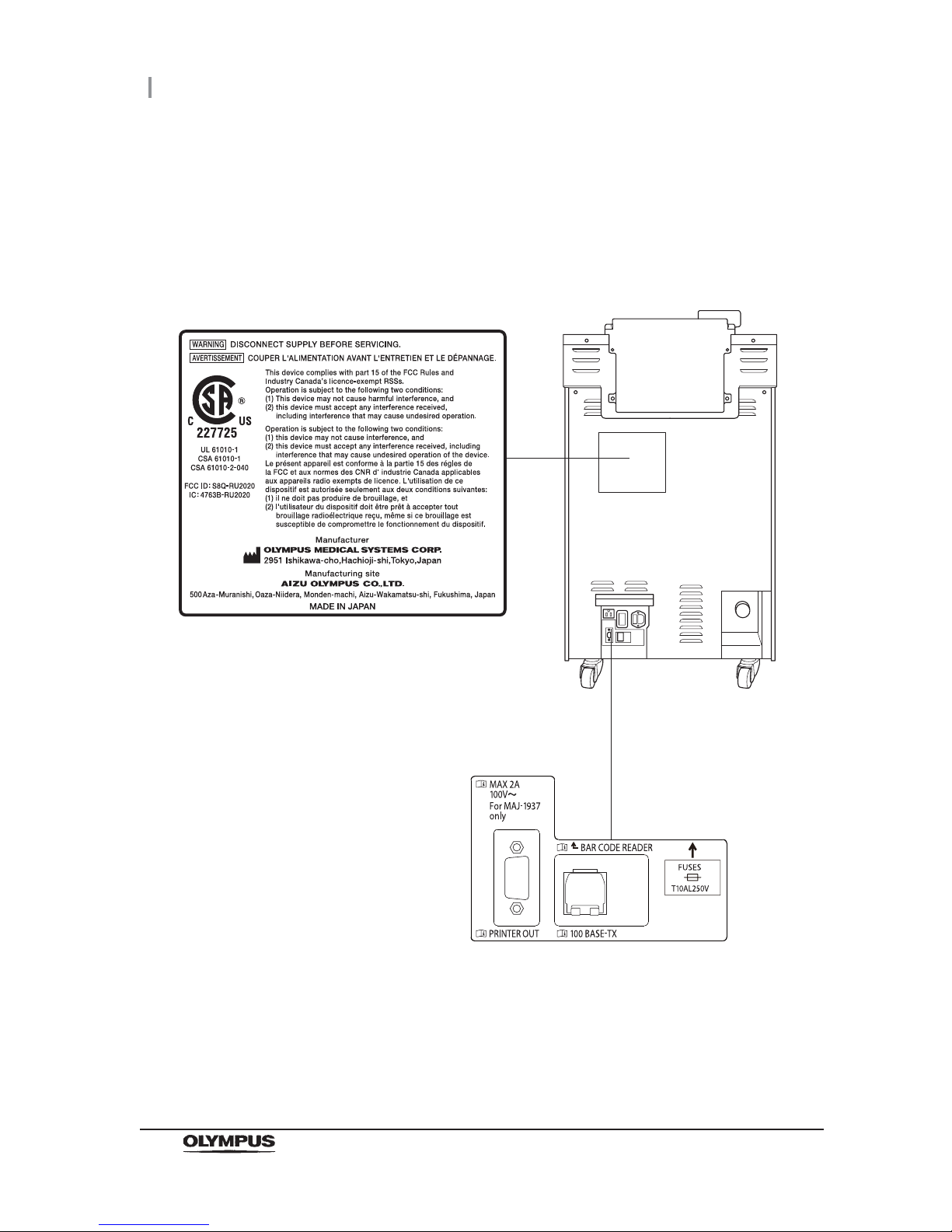
4
Labels and Symbols
OER-Elite OPERATION MANUAL
Rear panel
CSA/UL MARKING
Page 15
Labels and Symbols
5
OER-Elite OPERATION MANUAL
Top panel
Rotation direction
indicator label
Indicates the rotation
directions for locking
and releasing gas filter
case (lid).
FRA
FRA
FRA
Page 16

6
Labels and Symbols
OER-Elite OPERATION MANUAL
Reprocessing basin
Fonts displayed on the touch screen
Ricoh bitmap fonts designed by RICOH Company, Ltd. are used.
Page 17

Important Information — Please Read Before Use
7
OER-Elite OPERATION MANUAL
Intended use
The OER-Elite is intended for use in cleaning and high-level disinfection of heat sensitive Olympus
flexible endoscopes, their accessories, and endoscope reprocessor accessories. Safe use requires
detergent and an FDA-cleared high-level disinfectant/sterilant that Olympus has validated to be
efficacious and compatible with the materials of the OER-Elite and Olympus flexible endoscopes, their
accessories, and endoscope reprocessor accessories. Use of a detergent or high-level
disinfectant/sterilant that has not been validated by Olympus may be ineffective and can damage the
OER-Elite components and the endoscopes being reprocessed. Endoscopes must be cleaned by the
user prior to reprocessing; however, use of the OER-Elite enables the user to perform modified manual
cleaning of some endoscopes prior to automated cleaning and high-level disinfection in the OER-Elite.
Instruction manuals
The instructions for this reprocessor are divided into two volumes: “Instructions-Installation Manual”,
and “Instructions-Operation Manual”.
Instructions regarding the preparation of endoscopes prior to placing them in the OER-Elite are found
in “Instructions-Operation Manual”.
Each of these manuals contains essential information for using this reprocessor safely and effectively.
The “Instructions-Installation Manual” describes how to install the reprocessor. The
“Instructions-Operation Manual” describes how to operate and maintain the reprocessor and describes
modifications to the manual endoscope cleaning process that can save the user time and
inconvenience, if the endoscope is going to be subsequently reprocessed using the OER-Elite.
The “List of Compatible Endoscopes/Connecting Tubes <OER-Elite>” identifies all Olympus model
endoscopes that are compatible with the OER-Elite, plus the specific connecting tube(s) required for
each of these endoscope models.
The descriptions in these manuals assume that all endoscopes are reprocessed in the OER-Elite using
both an Olympus-validated detergent and disinfectant. Contact Olympus to obtain the list of both
Olympus-validated disinfectant solutions and detergents.
Before using this reprocessor, be sure to review all of the above-mentioned manuals, the safety
information provided with Olympus-validated detergents and disinfectants, and the manuals for all
other equipment used in the process. Always use this reprocessor as instructed. It might cause
unexpected danger if you do not follow the installation and operation manual. Keep these and all
related instruction manuals and documents in a safe and accessible location.
If you have any questions or comments about any information in these manuals, contact Olympus.
Important Information — Please Read Before Use
Page 18

8
Important Information — Please Read Before Use
OER-Elite OPERATION MANUAL
Terms used in these manuals
ALT
Stands for Auto Leak Test.
Air purge
In this operation, air is fed into an endoscope channel to blow out residual fluid. This
operation is usually performed automatically during a process, but it can also be activated
independently. Air purge is also used to drain cleaning fluid or disinfectant solution from
inside the reprocessor when the operation has stopped due to an error code, etc.
Alcohol
70% ethyl alcohol or 70% isopropyl alcohol.
Alcohol flush
To assist in drying the channels after reprocessing, alcohol is flushed through the
endoscope channels followed by air. This operation can be performed as the last step of
the reprocessing program or as an independent operation.
Automatic processing
When the reprocessor is stopped by the operator or due to an error, it identifies its status
and executes the optimum operation automatically. For example, if the reprocessor stops
in the middle of the disinfection process, it terminates the disinfection process and
removes the disinfectant solution.
Channel blockage monitoring
This function monitors the channel blockage of endoscope’s suction channel due to a
foreign object, etc., during a reprocessing program.
Channel connectivity monitoring
This function monitors the connection status of the connecting tubes during a
reprocessing program.
Channel monitoring
“Channel monitoring” will be used as a generic term meaning “Channel connectivity
monitoring” and “Channel blockage monitoring”.
Cleaning fluid
Refers to filtered water with detergent that is used during the cleaning process.
Cleaning process
A series of operations programmed into the reprocessor that enable it to perform
ultrasonic cleaning and detergent cleaning of endoscopes.
Page 19

Important Information — Please Read Before Use
9
OER-Elite OPERATION MANUAL
Detergent
Olympus-validated detergent. Refer to Section 2.8, “Consumable accessories (Optional)”
for details.
Disinfectant solution
Olympus-validated disinfectant solution. Refer to Section 2.8, “Consumable accessories
(Optional)” for details.
Disinfection process
A series of operations programmed into the reprocessor that enable it to perform
disinfection of endoscopes.
Error code
A code consisting of [E] and a three-digit number. This code is displayed on the touch
screen if there is a problem with the reprocessor. When an error code is displayed, check
the troubleshooting guide.
LCG
Liquid Chemical Germicide. It refers to disinfectant solution displayed on GUI.
Leak test
A test to confirm that an endoscope is free of leaks. This reprocessor is capable of both
the auto leak test and the manual leak test.
Manual cleaning
Cleaning of an endoscope by hand.
Modified precleaning and manual cleaning
A precleaning and manual cleaning method that is simplified due to subsequent use of the
OER-Elite which automates cleaning steps in the process.
MRC
Minimum Recommended Concentration.
Patient ID
Identity information specific to each patient. It can be recorded in the histories of
reprocessing, etc. For the patient ID input method, refer to Section 3.6, “Entering ID”.
Physician ID
Identity information specific to each endoscopist. It can be recorded in the histories of
reprocessing, etc. For the physician ID input method, refer to Section 3.6, “Entering ID”.
Portable memory
A digital medium for storage.
Page 20

10
Important Information — Please Read Before Use
OER-Elite OPERATION MANUAL
Precleaning
Cleaning of an endoscope performed after each procedure at the bedside in the
endoscopy room.
Procedure ID
Identity information specific to each procedure of the patient. It can be recorded in the
histories of reprocessing, etc. For the procedure ID input method, refer to Section 3.6,
“Entering ID”.
Process
Generic term for any operation, including cleaning and disinfection that is performed
automatically by this reprocessor.
Reprocessing process
A series of operations for ultrasonic cleaning, detergent cleaning, disinfection, rinse, air
purge, and alcohol flush of the outer surface or channels of endoscopes that run in a
specified sequence and for a specified time. Reprocessing programs [1] to [4] can be
selected by the user. Programs [1] to [4] have a fixed cleaning process time and
disinfection process time. They also have different patterns of auto leak test and channel
monitoring respectively.
Scope ID
Identity information specific to each endoscope. It can be recorded in the historical data of
reprocessing, etc. For the scope ID input method, refer to Section 3.6, “Entering ID”.
Shelf life
The date of expiration of the effectiveness of a detergent or disinfectant before it is
opened.
Test strip
Device used to test if the concentration of disinfectant solution is effective for disinfection.
Refer to Section 2.8, “Consumable accessories (Optional)” for details. (i.e., the minimum
recommended concentration (MRC) specified by the disinfectant manufacturer)
User ID
Identity information specific to each reprocessing operator. It can be recorded in the
histories of reprocessing, etc. For the user ID input method, refer to Section 3.6, “Entering
ID”.
Page 21

Important Information — Please Read Before Use
11
OER-Elite OPERATION MANUAL
User qualifications
The operator of this reprocessor must be sufficiently trained in reprocessing of endoscopes. The
medical literature reports cases of infections due to inappropriate cleaning, disinfection, and /or
sterilization. Thoroughly review and understand the following items before use:
Cleaning, disinfection, and sterilization procedures described in the instruction manuals for
the endoscope and ancillary equipment.
Professional health and safety standards.
Applicable guidelines on cleaning, disinfection, and sterilization of endoscopy equipment.
Structure and handling of endoscopic equipment.
Personal protective equipment requirements to minimize exposure to chemicals and
infectious materials.
These manuals do not explain or discuss detailed cleaning, disinfection, and sterilization procedures.
For more details, consult your facility’s procedures, professional guidelines, and regulatory
requirements for reprocessing endoscopes.
Page 22

12
Important Information — Please Read Before Use
OER-Elite OPERATION MANUAL
Ensuring the safety of reprocessing personnel
• Disinfectant solution and detergent may irritate the mucous membranes in the eyes and
respiratory organs. If disinfectant solution contacts the skin directly and eyes, it may cause
irritation or damage. Therefore, before handling high-level disinfectant solution and detergent,
carefully read the instructions for use and the safety data sheet. For further details, contact
Olympus.
• While using chemicals, wear appropriate personal protective gear to prevent contact with or
inhalation of chemicals or infectious substances. Personal protective gear includes eyewear,
face mask, moisture-resistant clothing, and chemical-resistant gloves that fit properly and are
long enough so that your skin and eyes is not exposed. All personal protective gear should be
inspected before use and replaced periodically before it is damaged.
• When using disinfectant solution and alcohol, Olympus recommends the use of gas filters and
running this reprocessor in well-ventilated areas.
Wear a face mask, gloves, and protective clothes to minimize aspiration and skin contact.
Wear goggles for eye protection.
Refer to the following association’s guidelines related to ventilation:
If the person operating the reprocessor exhibits an allergic reaction or symptoms, no matter
how slight, they should discontinue the task they are performing and vacate the room.
• Before handling the detergent or disinfectant, read the SDS (material safety data sheets) and
learn what measures to take in the event of exposure.
• Operators who exhibit symptoms of an allergic reaction or sensitivity to the reprocessing
chemicals should not operate this reprocessor.
• This reprocessor can be set up to use the RFID (Radio Frequency Identification) function. Be
aware that the radio waves emitted from the RFID reader of the reprocessor may cause
medical devices such as pacemakers to malfunction. If any interference with the equipment is
found, immediately move away from the RFID reader or set the power switch to OFF. Contact
a medical professional immediately if symptoms persist.
SGNA (Society of Gastroenterology Nurses and Associates)
ASGE (American Society of Gastroenterological Endoscopy)
APIC (Association for Professionals of Infection Control and Epidemiology)
AORN (Association of Preoperative Registered Nurses)
ASTM (American Society for Testing and Materials)
OSHA (Occupational Safety and Health Administration)
ACGIH (American Conference of Governmental Industrial Hygienists)
NIOSH (National Institute for Occupational Safety and Health)
AIA (American Institute of Architects)
Page 23

Important Information — Please Read Before Use
13
OER-Elite OPERATION MANUAL
Equipment compatibility
Use the OER-Elite in combination with ancillary equipment listed in “System chart” on page 647. Using
incompatible equipment may result in patient or operator injury and equipment damage and/or
malfunction.
Olympus has not tested the efficacy of reprocessing on the OER-Elite in combination with endoscopes
that are not listed on the “List of compatible Endoscopes/Connecting Tubes <OER-Elite>”.
If using endoscopes that are not listed on the “List of compatible Endoscopes/Connecting Tubes
<OER-Elite>”, reprocessing of endoscopes may be insufficient.
Care and storage
After use, reprocess and store this reprocessor referring to the instructions in Chapter 10, “End-of-Day
Checks” in this manual. Inappropriate care and storage could present an infection control risk and/or
cause reprocessor damage or malfunction.
Maintenance and Inspection
• The OER-Elite requires routine maintenance and inspection. In addition to checks before use,
the person in charge of maintenance and administration of the medical equipment at the
facility should periodically check all of the items described in this manual. If any irregularity is
found, do not use the reprocessor and inspect it as described in Section 13.2,
“Troubleshooting guide”. If the irregularity is still present, the reprocessor must be repaired
prior to next use.
• If the PERIODIC MAINTENANCE indicator starts to indicate on the touch screen, described
in Section 2.7, “Control panels”, the time for regularly scheduled maintenance is near. Contact
Olympus to perform the maintenance.
Repair and modification
Do not disassemble, modify, or attempt to repair this reprocessor and its accessories. Doing so could
result in operator or patient injury and/or equipment damage or malfunction. Some problems that
appear to be malfunctions may be corrected by referring to Chapter 13, “Troubleshooting and Repair”.
If the problem cannot be resolved using the information in Chapter 13, “Troubleshooting and Repair”,
contact Olympus.
Page 24
14
Important Information — Please Read Before Use
OER-Elite OPERATION MANUAL
Disposal of disinfectant solution
Expired disinfectant solution for this reprocessor should be handled as directed in the
Olympus-validated disinfectant product label and instructions. Follow all applicable national, state, and
local guidelines.
Disposal of this reprocessor
When disposing of this reprocessor and accessories, follow all applicable national, state, and local
regulations and guidelines.
Signal words
The following signal words are used throughout these manuals:
Warnings and cautions
Follow the warnings and cautions given below when handling this reprocessor. This information is
supplemented by warnings given in each chapter.
WARNING
• Do not insert an EndoTherapy accessory or other object through an opening
including the air vent of the reprocessor.
• Do not allow any liquid (including water or disinfectant solution) to flow into an
opening. Contact with an electrical part inside the reprocessor could cause an
electric shock or reprocessor failure.
• Always remove the tank from the detergent/alcohol drawer before putting detergent
or alcohol in the tank. If detergent or alcohol is spilled on the detergent/alcohol
drawer, it could get inside the reprocessor and contact an electrical part inside,
causing an electric shock or fire hazard.
Indicates a potentially hazardous situation which, if not avoided, could result in
death or serious injury.
Indicates a potentially hazardous situation which, if not avoided, may result in minor
or moderate injury. It may also be used to alert against unsafe practices or potential
equipment damage.
Indicates additional helpful information.
WARNING
CAUTION
NOTE
Page 25

Important Information — Please Read Before Use
15
OER-Elite OPERATION MANUAL
WARNING
• Do not install this reprocessor in any place where any of the following are present.
High oxygen concentration
Oxidizing substance such as Nitrous Oxide (N
2
O)
Flammable anesthetic gas
This reprocessor is not explosion-proof and may explode or cause a fire under
these conditions.
• Always use the power cord provided with this reprocessor. Otherwise, reprocessor
failure or power cord burnout may result. Also, remember that the provided power
cord is for use only with this reprocessor and should not be used with any other
equipment.
CAUTION
• Do not press any of the switches on the control panel of this reprocessor with a
pointed or hard object. Otherwise, the switch may be damaged.
• Be sure to turn off the water faucet and the power switch of the reprocessor at the
end of the day to avoid potential water leaks.
• To avoid malfunctions, do not use this reprocessor in a dusty environment.
• To avoid electromagnetic interference from other equipment, do not install any
other electrical devices in close proximity to this reprocessor (aside from ancillary
devices used with this reprocessor).
• This equipment enables radio communication by RFID and emits RF (radio
frequency: 13.56 MHz) energy to perform the said intended functions. It may cause
electromagnetic interference in nearby electronic equipment, and is labeled with
the symbol below. If electromagnetic interference occurs, mitigation measures may
be necessary, such as moving the electronic equipment away, reorienting or
relocating this instrument, or shielding the location. An electromagnetic
interference with other devices may shorten the communications distance of the
designated ID tag and cause signals to become unreadable. Try to take mitigation
measures such as keeping the affecting device away from this equipment.
Page 26

16
Outline of Functions
OER-Elite OPERATION MANUAL
Following functions are available in this reprocessor.
Reprocessing
A series of operations that enable the reprocessor to perform ultrasonic cleaning, detergent
cleaning, disinfection, rinse, air purge, and alcohol flush. A series of operations for ultrasonic
cleaning, detergent cleaning, disinfection, rinse, air purge, and alcohol flush of the outer surface
and channels of endoscopes in a specified sequence and for a specified time. Reprocessing
programs [1] to [4] can be selected by the user. Programs [1] to [4] have a fixed cleaning
process time and disinfection process time. They also have different patterns of auto leak test
and channel monitoring respectively. For details, refer to Chapter 6, “Reprocessing Operations”.
Heat LCG
A process for heating disinfectant solution until it reaches the specified temperature (22q, 72qF).
This process is performed automatically during the reprocessing program. It can also be
performed as an independent operation. For details, refer to Section 7.2, “Heat LCG”.
Heat LCG Timer
The function for heating the disinfectant solution until the specified temperature (22q, 72qF) by
the specified time. For details, refer to Section 7.3, “Heat LCG Timer”.
Drain LCG
This function drains the disinfectant solution from the disinfectant tank. For details, refer to
Section 8.2, “Replacing the disinfectant solution”.
Load LCG
This function loads the disinfectant solution after inserting a new disinfectant bottle. For details,
refer to Section 8.2, “Replacing the disinfectant solution”.
Mix LCG
This function mixs the disinfectant solution to the appropriate concentration and enables
accurate concentration check.
Outline of Functions
Page 27

Outline of Functions
17
OER-Elite OPERATION MANUAL
Water line disinfection
This function disinfects the water supply line and other lines inside the reprocessor. For details,
refer to Section 7.7, “Water line disinfection”.
Self disinfection and water sampling
This function disinfects the basin and internal piping of the reprocessor. End of the process,
sampling of rinse water can be performed for microbiological surveillance. For details, refer to
Section 7.8, “Self-disinfection and water sampling”.
Detergent/Alcohol line disinfection
This function disinfects the detergent line and alcohol line of the reprocessor. For details, refer to
Section 7.9, “Detergent line disinfection” and Section 7.10, “Alcohol line disinfection”.
Auto leak test
The endoscope leak test can be executed automatically by programming it in a user-configured
reprocessing process. It can also be performed as an independent operation. For details, refer
to Section 7.12, “Auto leak test”.
Manual leak test
Manual inspection for endoscope leakage during immersion of water can be performed as an
independent operation. For details, refer to Section 7.11, “Manual leak test”.
Alcohol flush
To assist in drying the channel after reprocessing, alcohol is flushed through the endoscope
channels followed by air. This function performs alcohol flush into the endoscope channels. The
alcohol flush can be executed automatically in a reprocessing process. It can also be performed
as an independent operation. For details, refer to Section 7.14, “Alcohol flush”.
Air purge
This function drains the remaining fluid from the basin after an irregularity occurs, or if the
process is stopped before it completes. Air purge also eliminates residual fluid from the
endoscope channels. For details, refer to Section 7.6, “Air purge”.
Page 28

18
Outline of Functions
OER-Elite OPERATION MANUAL
Rinse
This function performs the rinsing process if the fluid remains in the basin or in the endoscopes
after an irregularity occurs or the process is stopped midway. For details, refer to Section 7.5,
“Rinse”.
Leaking scope decontamination
This function decontaminates a leaking endoscope prior to repair. During the decontamination,
positive pressure is applied to the leaking endoscope to avoid fluid invasion and damage to the
endoscope. For details, refer to Section 7.15, “Leaking scope decontamination”.
ALT self-check
This function checks the auto leak test function of the reprocessor. It is performed automatically
at the end of Load LCG function or as an independent operation. For details, refer to
Section 7.13, “Self-check of auto leak test”.
Page 29
1.1 Checking the package contents
19
OER-Elite OPERATION MANUAL
Ch.1
Chapter 1 Checking the Package
Contents
Check that the package contains all the items listed below. Inspect each item for damage. If the device
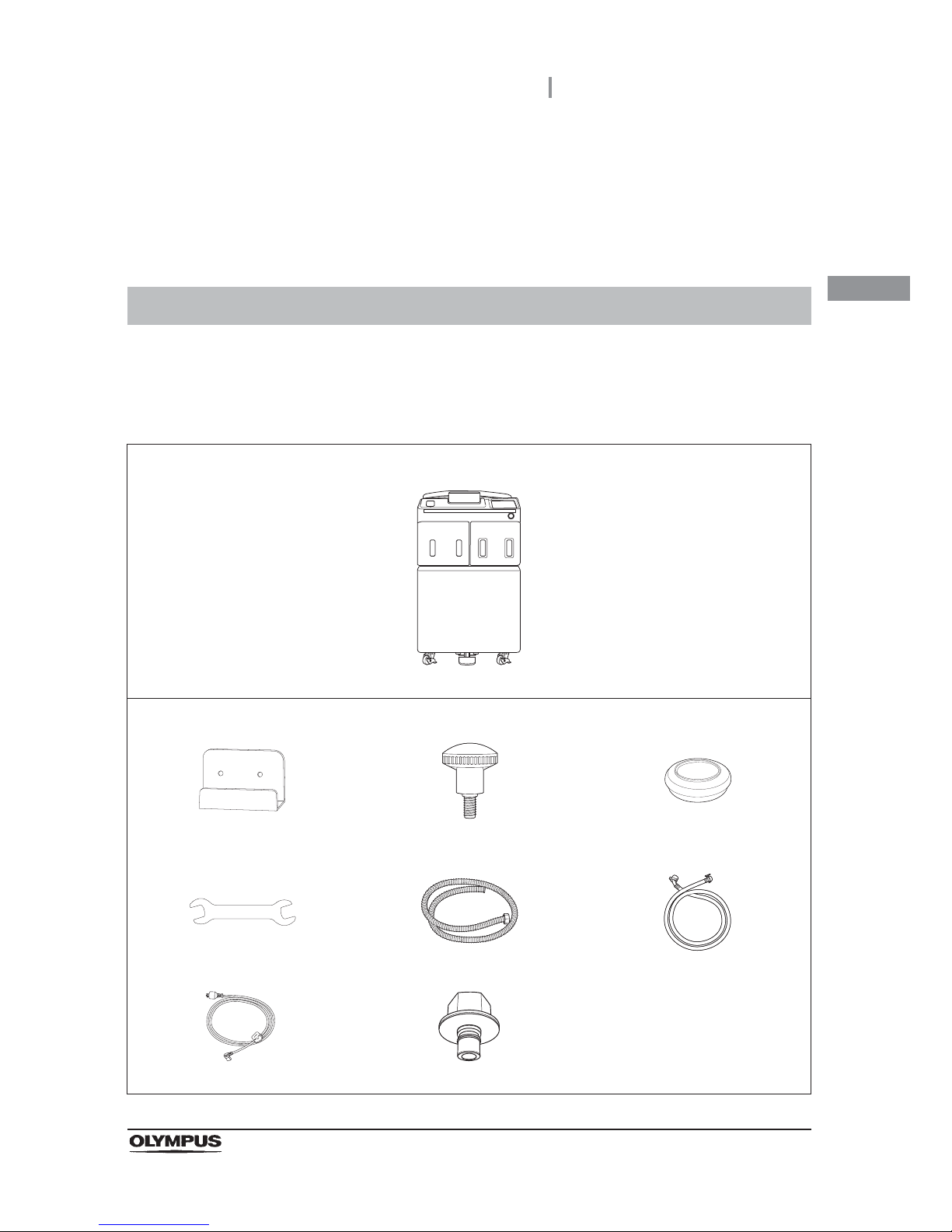
is damaged, a component is missing, or there is any question regarding items, do not use the device
and contact Olympus immediately.
1.1 Checking the package contents
Endoscope reprocessor
Endoscope reprocessor OER-Elite
Accessories for use in installation
Buckling guard (GT970400) Buckling guard retaining screw
(GC783700, 2 pcs)
Grommet (GC784100, 4 pcs)
Wrench (GC748400) Drain hose (GJ853400) Water supply hose (GC416500)
Power cord (RL545000) Water supply plug (GN573800)
Page 30
20
1.1 Checking the package contents
OER-Elite OPERATION MANUAL
Ch.1
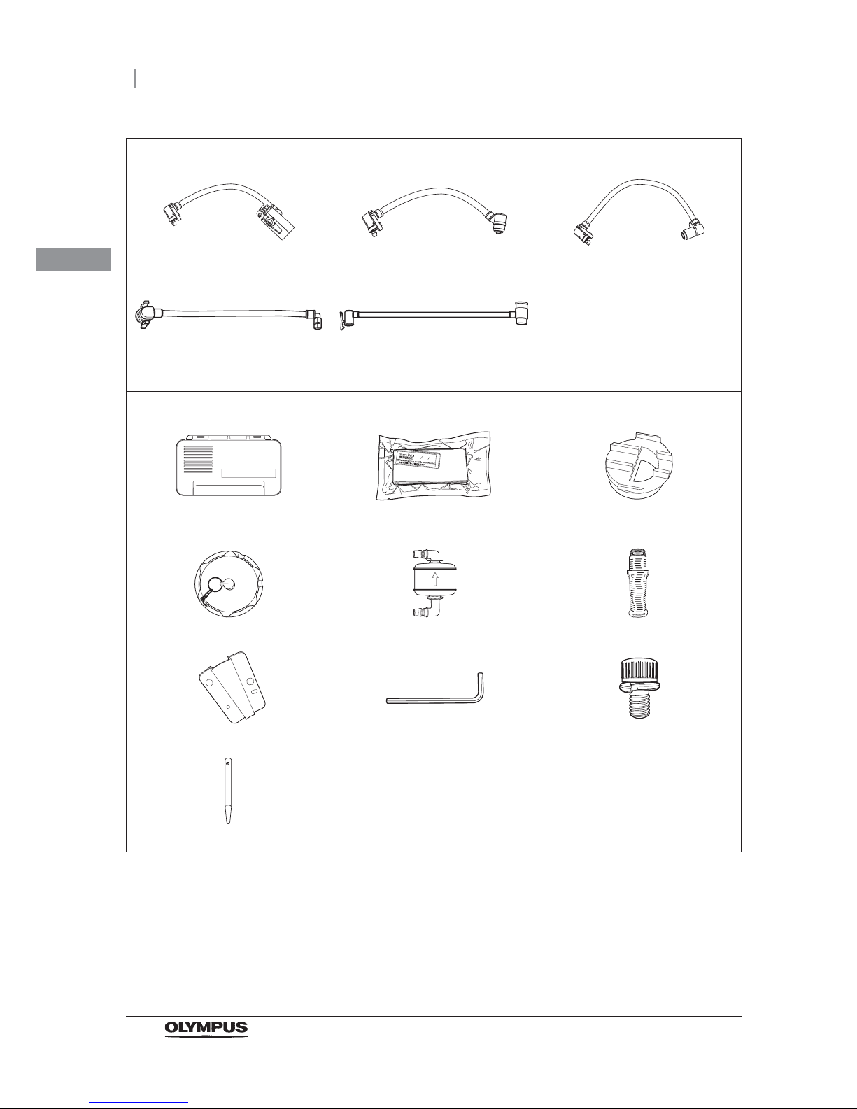
Accessories for use in reprocessing
Connecting tube (MAJ-2110, 2 pcs) Connecting tube (MAJ-2111, 2 pcs) Connecting tube (MAJ-2112, 2 pcs)
Connecting tube (MAJ-2113, 2 pcs) Leak test air tube
(MAJ-2127, 2 pcs)
Accessories to be attached to the reprocessor
Gas filter case (GJ460700) Gas filter (2 pcs) (MAJ-822) Gas filter adapter (splash guard)
(GC949900)
Washing case (MAJ-2121) Air filter (MAJ-823) Water filter (MAJ-824 or MAJ-2318)
Stylus pen holder (RA016500) Hex wrench (GT804300) M4 × 10 mm cap bolt (2 pcs)
Stylus pen (GT944200)
Page 31
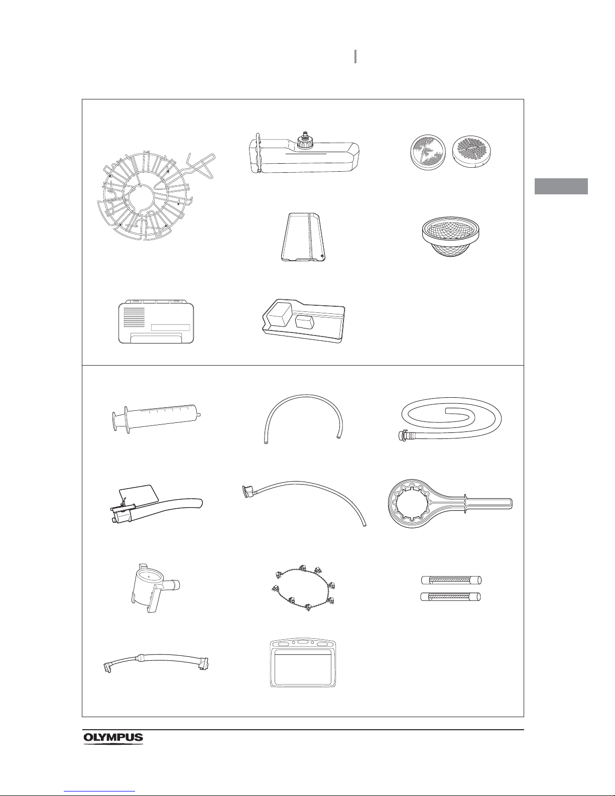
1.1 Checking the package contents
21
OER-Elite OPERATION MANUAL
Ch.1
Accessories preattached to the reprocessor
Retaining rack (GT943000)
Alcohol tank (RU715000) Circulation port mesh filter
(GC574000 and GC693900)
Detergent/alcohol inner tray
(GT647800)
Drain port mesh filter
(GC220100)
Gas filter case (GJ460700) Water tray (GT949200)
Accessories for use in maintenance
Syringe (GT173600) Tube (GC651300) Disinfectant collection hose
(GJ668000)
Disinfectant removal tube
(GJ460200)
Filter tube (GJ460500, 2 pcs) Water filter wrench (GC601300)
Drain connector (GL366300) Connector jig (RU726500) Spare fuse (DB181500, 2 pcs)
Water supply piping disinfection
hose (RU205800)
Card holder (GT271000, 2 pcs)
Page 32
22
1.1 Checking the package contents
OER-Elite OPERATION MANUAL
Ch.1
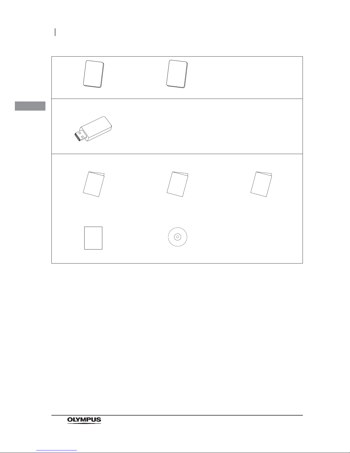
Scope ID master card (GT970700) User ID master card (GT970600)
Accessory for use in record management
Portable memory (MAJ-1925)
Manuals
Instructions-Installation Manual Instructions-Operation Manual
(this manual)
List of Compatible
Endoscopes/Connecting Tubes
<OER-Elite>
OER-Elite Quick Reference Guide OER-Elite Operation Guide
Page 33
2.1 Front panel
23
OER-Elite OPERATION MANUAL
Ch.2
Chapter 2 Nomenclature and
Functions
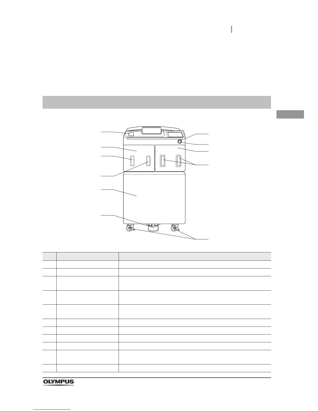
2.1 Front panel
No. Nomenclature Description
1 Power switch Press to turn the reprocessor ON or OFF.
2 Power indicator Lights up when the reprocessor is ON.
3 Disinfectant bottle drawer Accommodates disinfectant cassette bottles. This door can be opened when
the load LCG function is started.
4 Disinfectant bottle drawer
check windows
Check an inside of bottles in the disinfectant bottle drawer.
5 Casters The two front casters have lock mechanisms. The caster heights can be
adjusted to level the reprocessor.
6 Foot pedal Step to open the lid. It is locked during the reprocessing process.
7 Front door Push the area marked “PUSH” to open.
8 Alcohol tank check window Checks the amount of alcohol remaining.
9 Detergent tank check window Checks the amount of detergent remaining.
10 Detergent/alcohol drawer Accommodates the specially designed tanks of detergent for cleaning and
alcohol for alcohol flush.
11 Portable memory port Insert the portable memory into this port.
11
9
8
7
6
1
3
2
4
10
5
Page 34
24
2.2 Top panel
OER-Elite OPERATION MANUAL
Ch.2
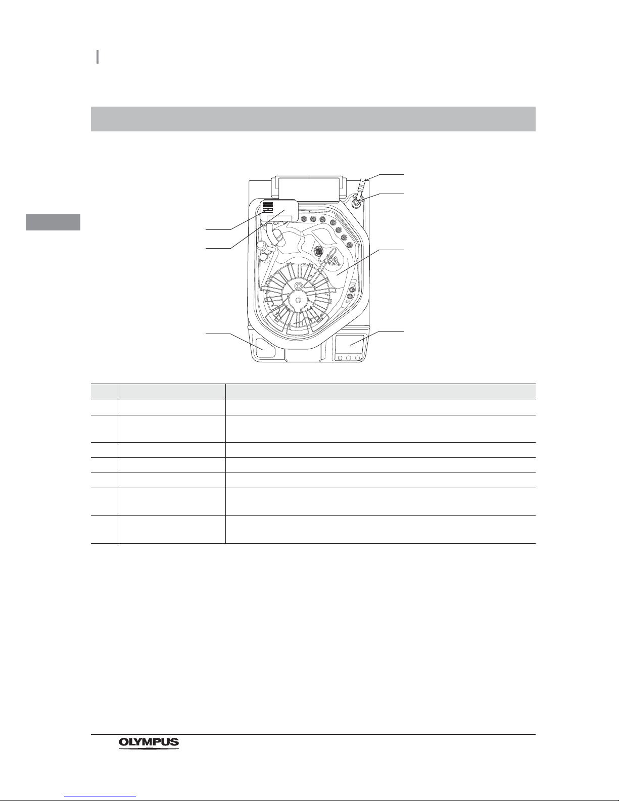
2.2 Top panel
No. Nomenclature Description
1 Water supply hose Supplies water for use in cleaning.
2 Water supply hose
connector
Connect the water supply hose. A mesh filter is built in this connector.
3 Lid Step on the foot pedal to open the lid.
4 Control panel Used for various setup and operation. Refer to Section 2.7, “Control panel”.
5 RFID reader Reads RFID tag for user ID, scope ID, and physician ID.
6 Gas filter case (lid) Accommodates the gas filter which removes the odor and vapor of the
disinfectant solution.
7 Ventilation openings on the
gas filter case
These are the slots for intake and exhaust of air into/from the reprocessing basin.
Do not block the ventilation openings on the gas filter case.
1
2
3
5
6
7
4
Page 35
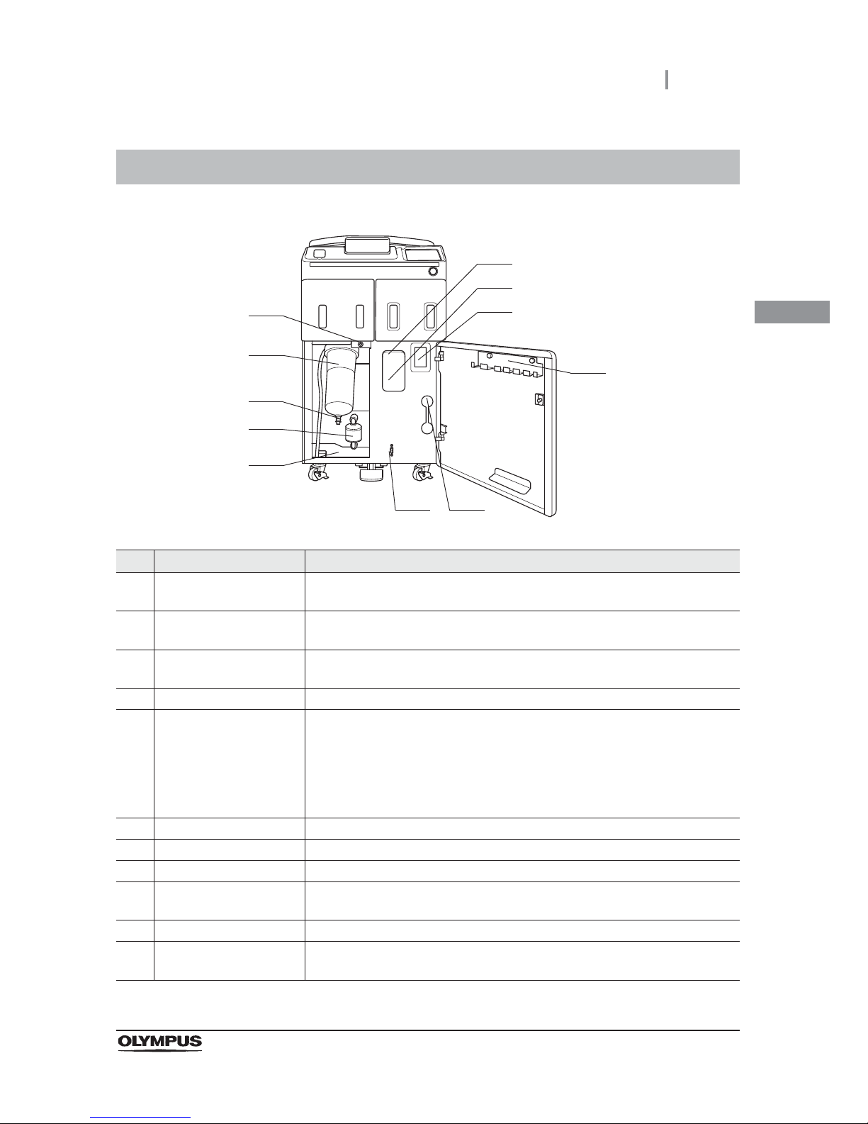
2.3 Inside
25
OER-Elite OPERATION MANUAL
Ch.2
2.3 Inside
No. Nomenclature Description
1 Gas filter case (tank) Accommodates the gas filter which removes the odor and vapor of the
disinfectant solution.
2 Ventilation opening on the
gas filter case
These are the slots for intake and exhaust of air into/from the disinfectant
solution tank. Do not block the ventilation openings on the gas filter cases.
3 Disinfectant solution tank
window
Used to check the amount of remaining disinfectant solution.
4 Accessory holder Used to store the connecting tubes, etc.
5 Disinfectant removal port Used to remove the residual disinfectant solution in the tank by using the
disinfectant removal tube.
It is also used to withdraw the amount of disinfectant solution by using the drain
connector for detergent/alcohol piping disinfection.
(Remove the rubber cap and attach the drain connector or the disinfectant
removal tube.)
6 Maintenance terminal Used for connecting ancillary equipment (for trained service personnel only).
7 Water tray Collects water during maintenance such as the water filter replacement.
8 Air filter Accommodates the 0.2-micron air filter.
9 Connector below water
filter housing
For use in draining water from the water filter housing.
10 Water filter (housing) Accommodates the 0.2-micron internal water filter.
11 Connector above water
filter housing
For use in draining water and air from the water filter housing.
1
2
3
4
56
7
8
9
10
11
Page 36
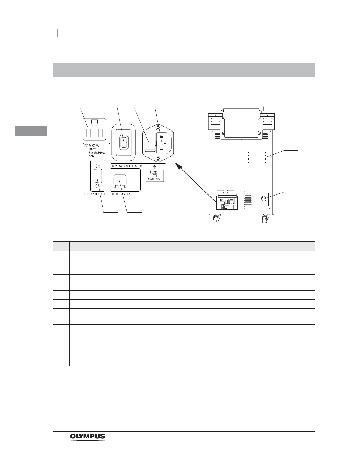
26
2.4 Rear panel
OER-Elite OPERATION MANUAL
Ch.2
2.4 Rear panel
No. Nomenclature Description
1 Printer outlet Connect the power cord of the printer (MAJ-1937) provided with the optional
printer set (MAJ-2144) to feed power to it. Do not connect any devices other than
the specified printer.
2 Bar code reader port Connect the optional bar code reader (MAJ-2130).
Do not connect any devices other than the specified bar code reader.
3 Fuse (BOX) Protects the reprocessor from an over-current.
4 Power cord receptacle Connect the power cord.
5 100BASE-TX terminal Used to access the Olympus-designated external devices (for trained service
personnel only).
6 Printer communication port Connects the printer (MAJ-1937) provided with the optional printer set
(MAJ-2144). Do not connect any devices other than the specified printer.
7 Buckling guard attaching
holes
Screw holes used to attach the buckling guard.
8 Drain hose connector Connect the drain hose.
1
7
2 3 4
56
8
Page 37
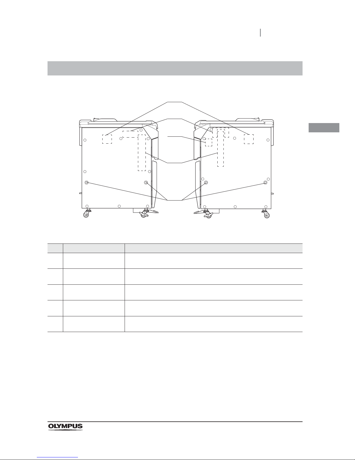
2.5 Side panel
27
OER-Elite OPERATION MANUAL
Ch.2
2.5 Side panel
No. Nomenclature Description
1 Bar code reader attaching
holes
Used to attach the optional bar code reader (MAJ-2130).
2 Printer set attaching holes Used to attach the optional printer set (MAJ-2144). The connector hanger cannot
be attached if the printer set is already attached.
3 Stylus pen holder attaching
holes
Used to attach the provided stylus pen holder.
4 Connector hanger
attaching holes
Used to attach the optional connector hanger (MAJ-865). The printer set cannot
be attached if the connector hanger is already attached.
5 Grommet attaching holes
(×4)
Used to attach the grommets.
1
Left Right
2
3
4
5
Page 38
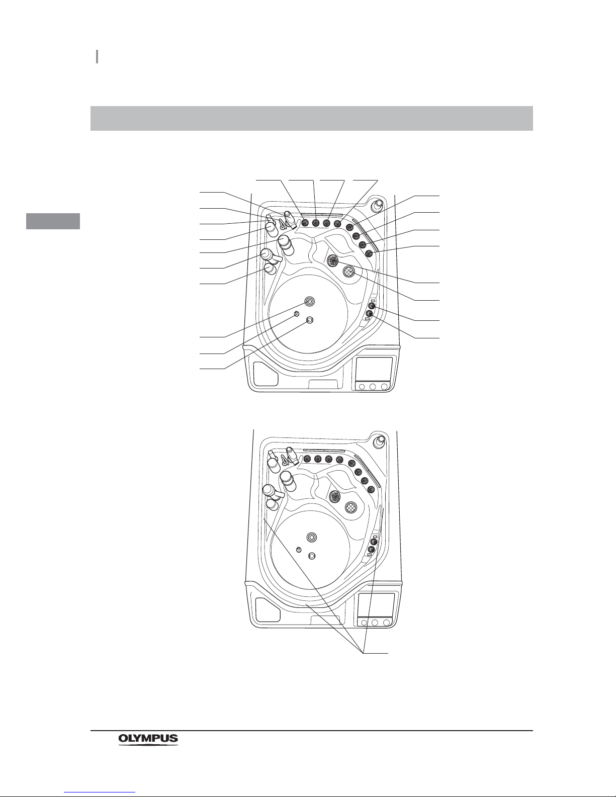
28
2.6 Reprocessing basin
OER-Elite OPERATION MANUAL
Ch.2
2.6 Reprocessing basin
1 2 3 4
5
6
7
8
11
12
13
14
15
16
17
18
19
20
21
22
23
9
10
Page 39
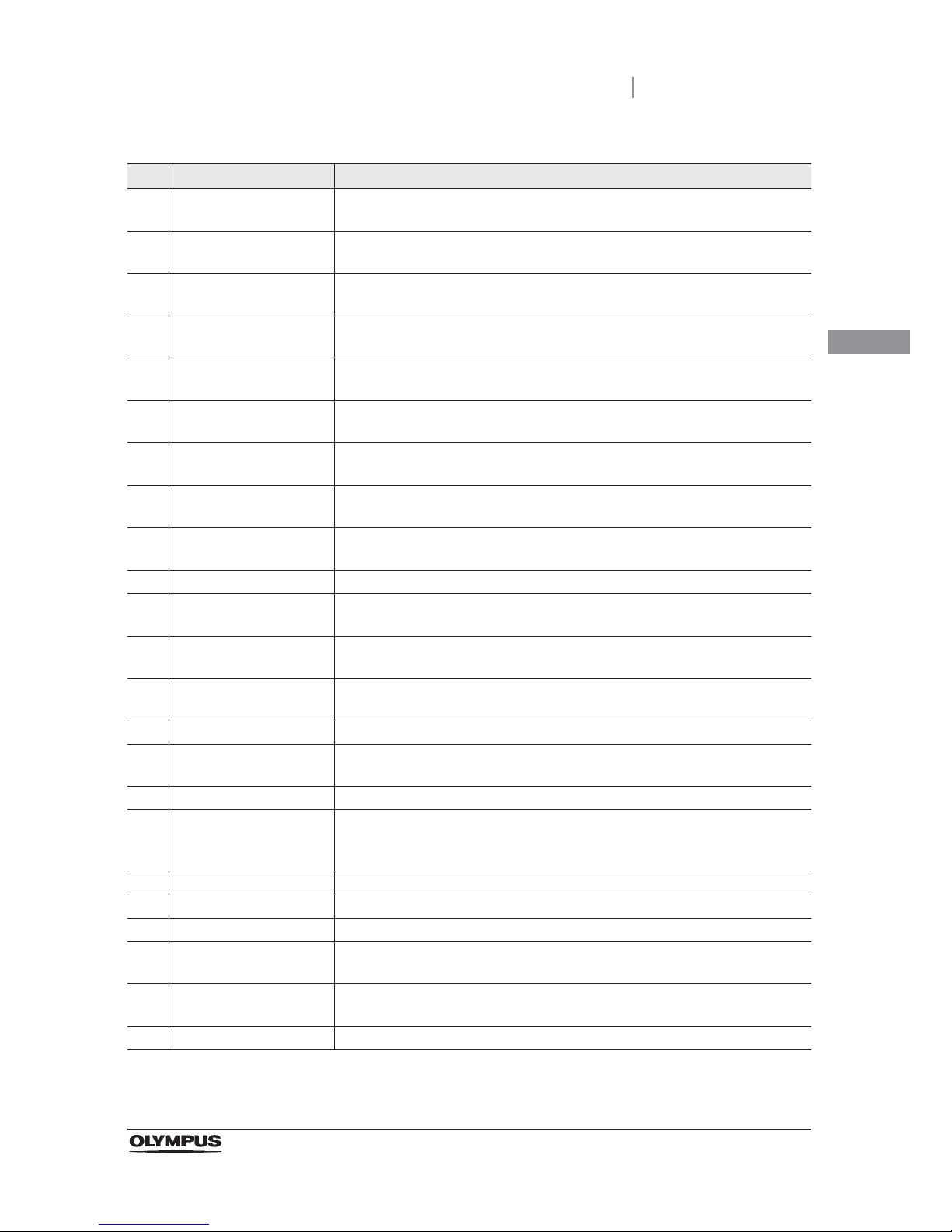
2.6 Reprocessing basin
29
OER-Elite OPERATION MANUAL
Ch.2
No. Nomenclature Description
1 Connector A2 (Light blue) Connect a connecting tube colored light blue.
This connector is mainly used for second endoscope.
2 Connector B2 (Blue) Connect a connecting tube colored blue.
This connector is mainly used for second endoscope.
3 Connector B1 (Blue) Connect a connecting tube colored blue.
This connector is mainly used for first endoscope.
4 Connector A1 (Light blue) Connect a connecting tube colored light blue.
This connector is mainly used for first endoscope.
5 Connector D2 (Orange) Connect a connecting tube colored orange.
This connector is mainly used for second endoscope.
6 Connector C2 (Green) Connect a connecting tube colored green.
This connector is mainly used for second endoscope.
7 Connector C1 (Green) Connect a connecting tube colored green.
This connector is mainly used for first endoscope.
8 Connector D1 (Orange) Connect a connecting tube colored orange.
This connector is mainly used for first endoscope.
9 Circulation port Aspirates the cleaning fluid or disinfectant solution for circulation during cleaning
or disinfection.
10 Drain port Drains liquid from the reprocessing basin.
11 Leak test connector E2
(Purple)
Connect the leak test air tube that is connected to the second endoscope here.
12 Leak test connector E1
(Purple)
Connect the leak test air tube that is connected to the first endoscope here.
13 Washing case mount Mount for the Washing case that is used to hold the endoscope accessories
including valves for reprocessing.
14 Temperature sensor Monitor the temperature of the fluid in the reprocessing basin.
15 Water supply piping
disinfection connector
Connect the water supply piping disinfection hose here.
16 Fluid level sensor Detects abnormal fluid level in the reprocessing basin.
17 Disinfectant solution
nozzle
Supplies disinfectant solution to the reprocessing basin. Also, used to check if
the disinfectant concentration meets the recommended level by the disinfectant
manufacturer. (Open the cap and insert the chemical indicator (test strip).)
18 Float switch (long) Detects the fluid level in the reprocessing basin to control it.
19 Detergent nozzle Supplies detergent to the reprocessing basin.
20 Float switch (short) Detects the fluid level in the reprocessing basin to control it.
21 Circulation nozzle Supplies the cleaning fluid or disinfectant solution aspirated through the
circulation port for circulation.
22 Water supply/circulation
nozzle
Supplies water for cleaning. Also, supplies the cleaning fluid or disinfectant
solution aspirated through the circulation port for circulation.
23 Water level scale (× 3) Marks for confirming that the reprocessor is level.
Page 40
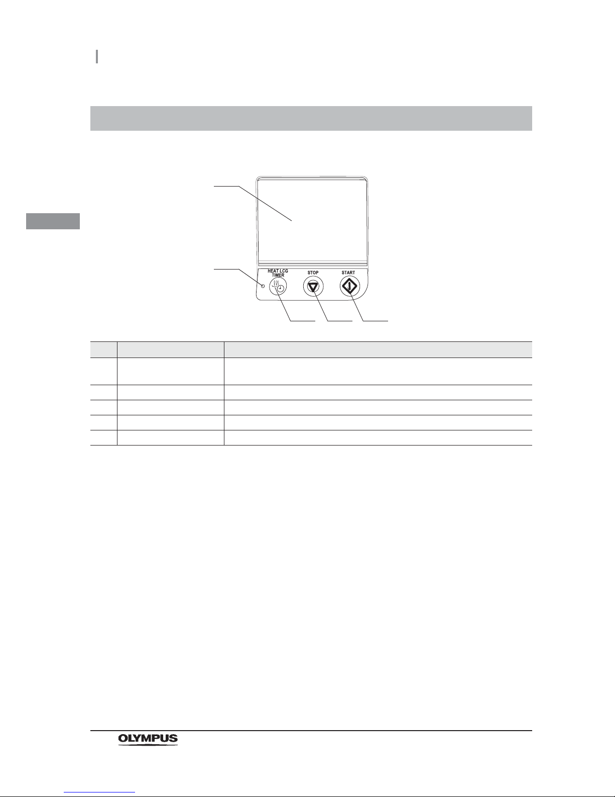
30
2.7 Control panels
OER-Elite OPERATION MANUAL
Ch.2
2.7 Control panels
No. Nomenclature Description
1 Touch screen Used to control and set the reprocessor. Also, the information and state of the
reprocessor can be displayed.
2 Heat LCG Timer indicator The indicator lights when the Heat LCG Timer is in progress.
3 Heat LCG Timer button Press this button to active the Heat LCG Timer.
4 Stop button Press this button to stop process.
5 Start button Press this button to start process.
1
3 4 5
2
Page 41
2.8 Consumable accessories (Optional)
31
OER-Elite OPERATION MANUAL
Ch.2
WARNING
Before using consumable items, be sure to check its shelf-life and expiration date
items. If these items are expired, effectiveness of items may be compromised.
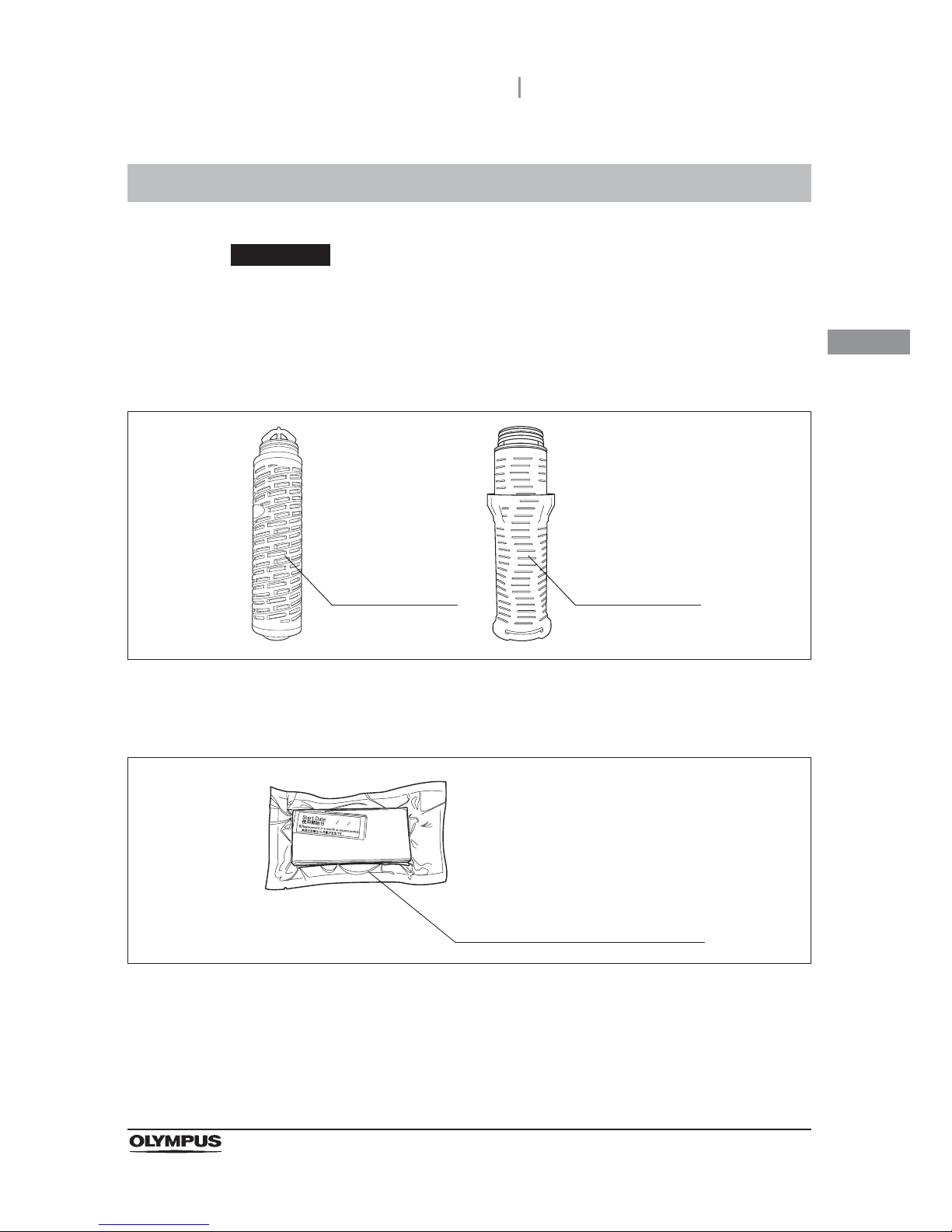
Water filter (MAJ-824 or MAJ-2318)
Figure 2.1
Gas filters (MAJ-822)
Figure 2.2
2.8 Consumable accessories (Optional)
Internal 0.2 micron
water filter.
Internal 0.2 micron
water filter.
Inserted in the gas filter cases to absorb
disinfectant odors and vapors.
Page 42
32
2.8 Consumable accessories (Optional)
OER-Elite OPERATION MANUAL
Ch.2
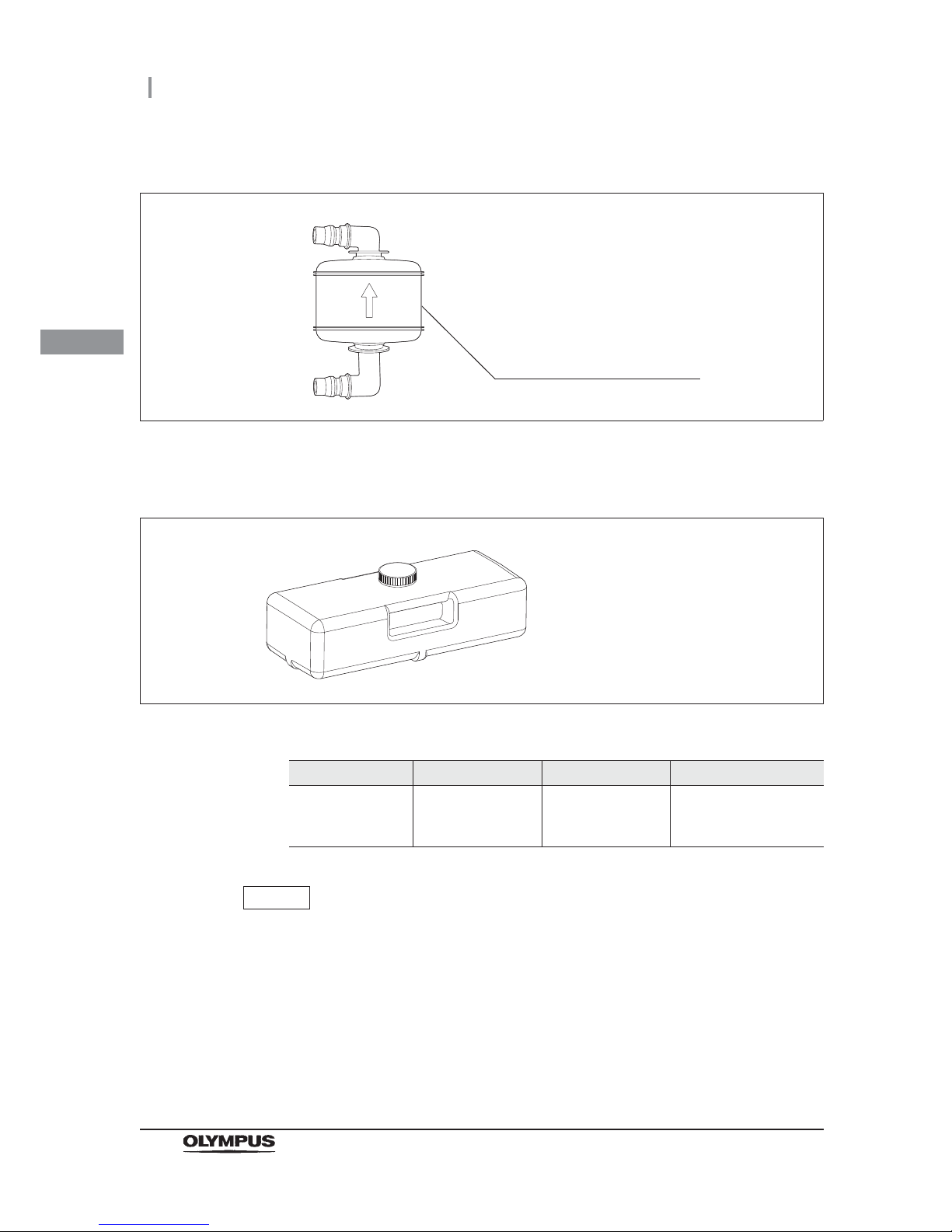
Air filter (MAJ-823)
Figure 2.3
Olympus-validated detergent
Figure 2.4
Table 2.1
NOTE
EndoQuick is distributed by Olympus America, Inc. To obtain EndoQuick listed
above, contact Olympus.
Name Type Manufacturer Remarks
EndoQuick Alkaline detergent
Best Sanitizers, Inc.
(154 Mullen Drive,
Walton, KY)
2.8 L disposable tank
Filters microorganisms and fine
particles in the air fed into the
reprocessor.
Page 43
2.8 Consumable accessories (Optional)
33
OER-Elite OPERATION MANUAL
Ch.2
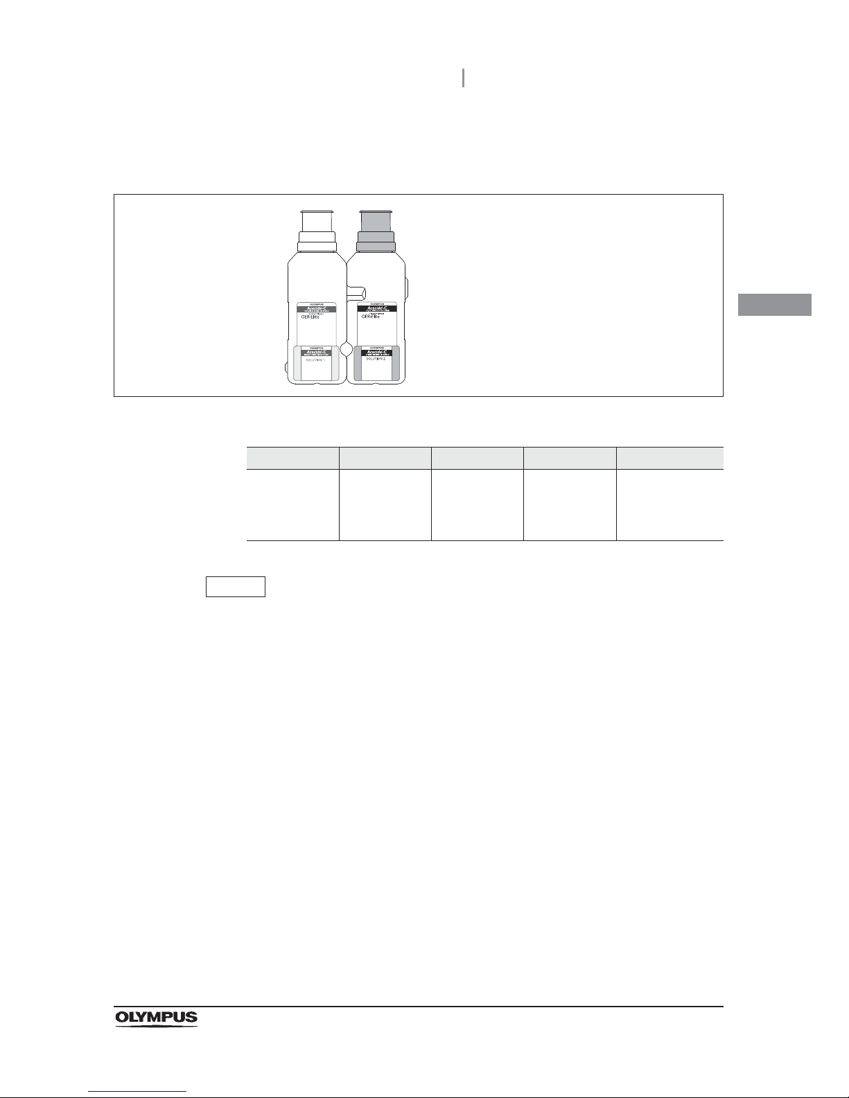
Olympus-validated concentrated disinfectant solution
(1,065 ml cassette bottles)
Figure 2.5
Ta bl e 2 .2
NOTE
Acecide-C is distributed by Olympus America, Inc. To obtain Acecide-C listed
above, contact Olympus.
Name Typ e Manufacturer Remarks 510(k) number
Acecide-C
Peracetic Acid
(PAA)
Best Sanitizers,
Inc. (154 Mullen
Drive, Walton,
KY)
1,065 ml
cassette bottles
For use in
OER-Elite
K091210
Page 44
34
2.8 Consumable accessories (Optional)
OER-Elite OPERATION MANUAL
Ch.2
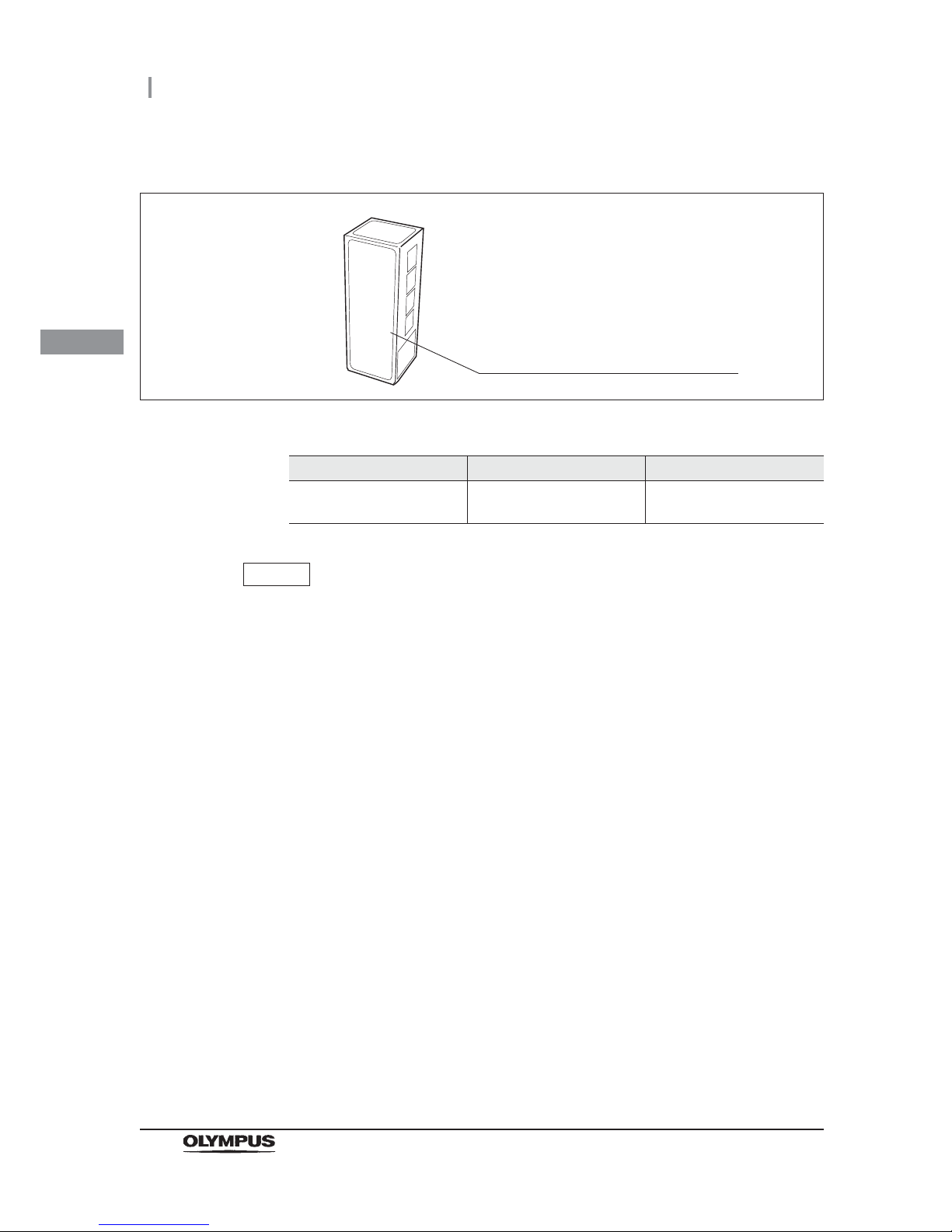
Chemical indicator (test strip)
Figure 2.6
Table 2.3
NOTE
ACECIDE test strips is distributed by Olympus America, Inc. To obtain ACECIDE
test strips listed above, contact Olympus.
Name Manufacturer 510(k) number
ACECIDE test strips
Best Sanitizers, Inc. (154
Mullen Drive, Walton, KY)
K091210
FDA-cleared Chemical indicator (test strip)
used to determine if Olympus-validated
disinfectant meets the minimum
recommended concentration.
Page 45
3.1 Turning power ON
35
OER-Elite OPERATION MANUAL
Ch.3
Chapter 3 Basic Operation
3.1 Turning power ON
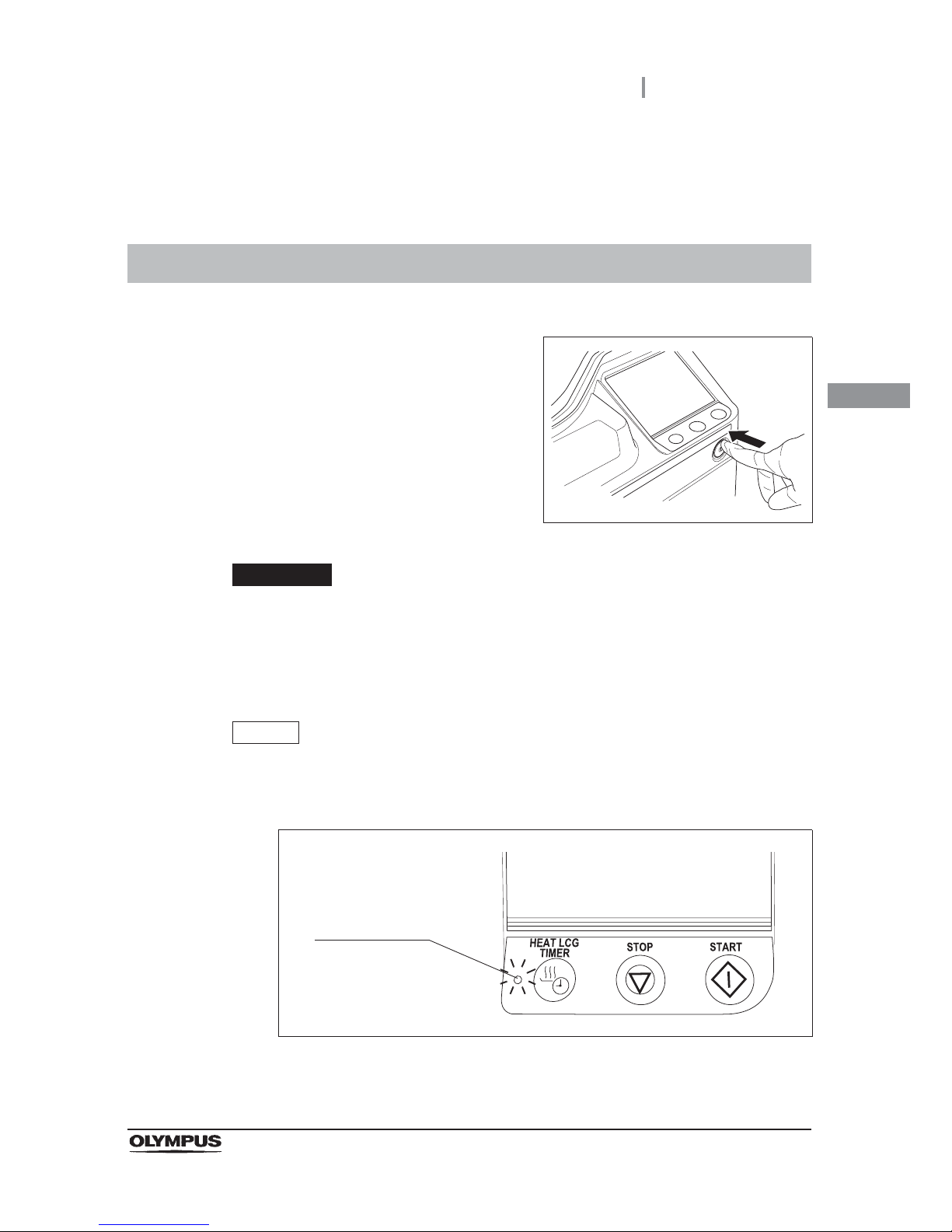
1 Press the power switch of the reprocessor.
Figure 3.1
CAUTION
Connect the connection ring on the reprocessor end of the water supply hose to
the water supply hose connection port by tightening securely. An insecure
connection may lead to a risk of a water leak. For detail, refer to Section 4.4
“Connection of the water supply hose” in “Instructions-Installation Manual”.
NOTE
Lighting of Heat LCG Timer indicator means that Heat LCG Timer is being
activated. For the operation during running of the Heat LCG Timer, refer to
Section 7.3, “Heat LCG Timer”.
Figure 3.2
Heat LCG Timer
indicator
Page 46
36
3.1 Turning power ON
OER-Elite OPERATION MANUAL
Ch.3
NOTE
• The Start Screen is set to “Menu screen” at the factory. For how to set the
Reprocessing Standby screen, refer to Section 4.18, “Start screen”.
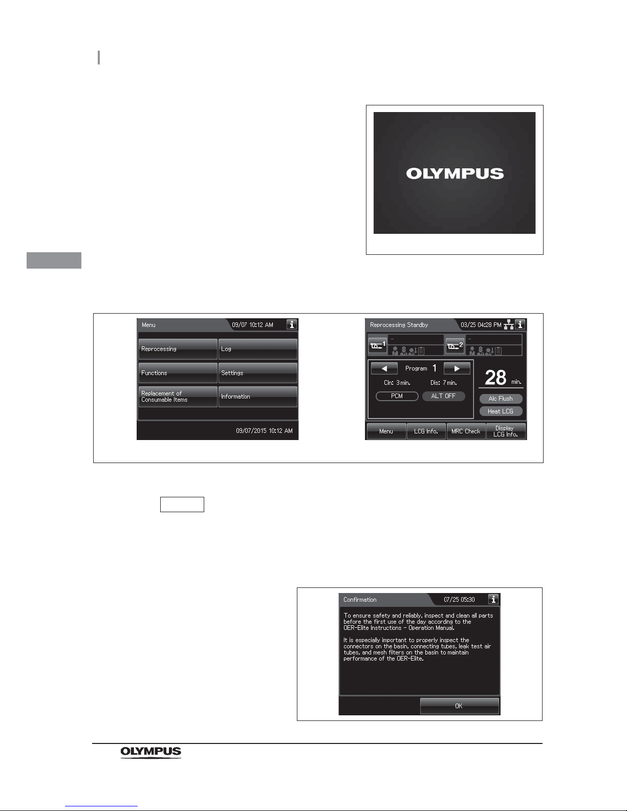
• Before using the reprocessor, always show the confirmation information. Refer to
Figure 3.5.
Figure 3.5
2 The power indicator lights up and the touch
screen displays the initial screen for few
seconds.
Figure 3.3
3 The Start screen appears. Start screen will display the Menu screen or Reprocess
standby screen.
Figure 3.4
Initial screen
Menu screen Reprocessing Standby screen
Page 47
3.2 Alarm indicator
37
OER-Elite OPERATION MANUAL
Ch.3
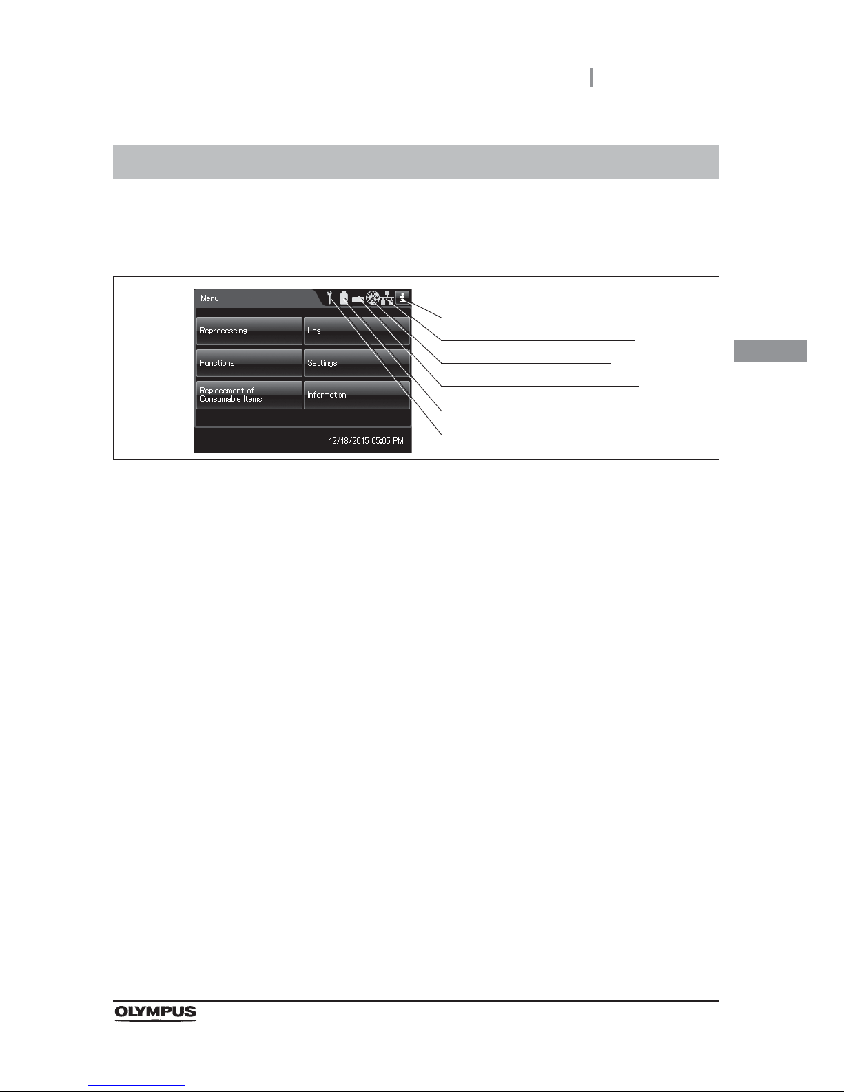
When the timing of periodical maintenance comes, the number of usage days or cycles of a
consumable item reaches the set value, shelf-life of the item expires or the network setting is
activated, the alarm indicator displays on the top right of the touch screen.
Figure 3.6
Periodic maintenance indicator
If the PERIODIC MAINTENANCE indicator starts to indicate on the touch screen, “Control
panels”, the time for regularly scheduled maintenance is near. Contact Olympus to perform the
maintenance.
If you do not know when the indicator started to light, do not use the reprocessor and contact
Olympus. Otherwise, the reprocessing may be insufficient.
3.2 Alarm indicator
Periodic maintenance indicator
Disinfectant solution replacement indicator
Detergent replacement indicator
Filter replacement indicator
Communication status indicator
Alarm indicator information button
Page 48

38
3.2 Alarm indicator
OER-Elite OPERATION MANUAL
Ch.3
Disinfectant replacement indicator
The indicator lights when the following reaches set value.
• The number of days of disinfectant usage
• The number of cycle count of disinfectant usage
• The number of day of shelf-life reaches
For how to set the disinfectant solution counter, refer to Section 4.12, “LCG replacement
indicator”.
For how to set the shelf-life, refer to Section 4.13, “LCG lot number and shelf-life management”.
WARNING
Be sure to check the concentration of the disinfectant solution by using the
separately available test strips. The disinfectant replacement indicator does not
determine the effectiveness of the disinfectant solution. The expiration of the
disinfectant solution varies depending on many factors including the time since
activation, the temperature of the environment where the reprocessor is installed,
and the number and types of endoscopes that have been reprocessed. The
disinfectant replacement indicator does not take these and other factors into
consideration.
Detergent replacement indicator
The indicator lights when the following reaches set value.
• The number of days of detergent usage
• The number of day of shelf-life reaches
For details on the setting change, refer to Section 4.10, “Detergent replacement indicator”.
For how to set the shelf-life, refer to Section 4.11, “Detergent lot number and shelf-life
management”.
Filter replacement indicator
The lamp light when the number of days of filter usage reaches set value.
The number of days of water filter usage.
The number of days of air filter usage.
The number of days of gas filter (lid) usage.
The number of days of gas filter (tank) usage.
For details on the setting change, refer to Section 4.14, “Filter replacement indicator”.
Page 49
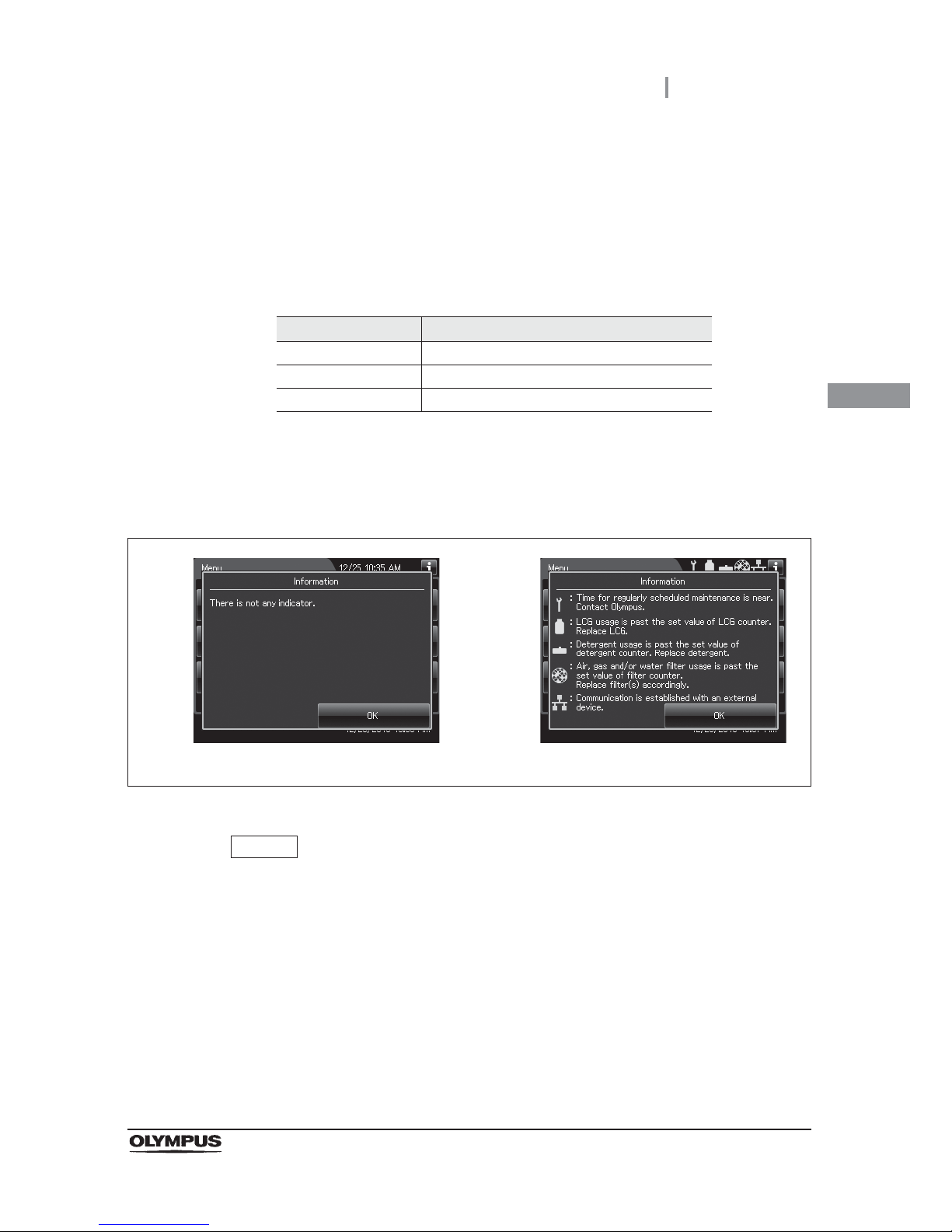
3.2 Alarm indicator
39
OER-Elite OPERATION MANUAL
Ch.3
Communication status indicator
This indicator shows the network status of the reprocessor. The network function setting and
connection status can be confirmed depending on the type of indicator. When the
non-connected status is displayed (yellow indicator), the reprocessor is not connected to a
network. Check the power supply to the external devices and the connection between the
external devices and the OER-Elite. If the problem cannot be resolved, contact Olympus.
Ta bl e 3 .1
Alarm indicator information button
Press the button to view the information about the displayed alarm indicator.
Figure 3.7
NOTE
• If the network function is disabled, the information screen does not show
information on the network.
• The information screen shows only the explanations of the warnings indicated by
the displayed alarm indicator.
Indicator Description
green Communication is established.
yellow Communication is interrupted.
Not displayed Communication setting is OFF.
When no alarm indicator is displayed When alarm indicators are displayed
Page 50
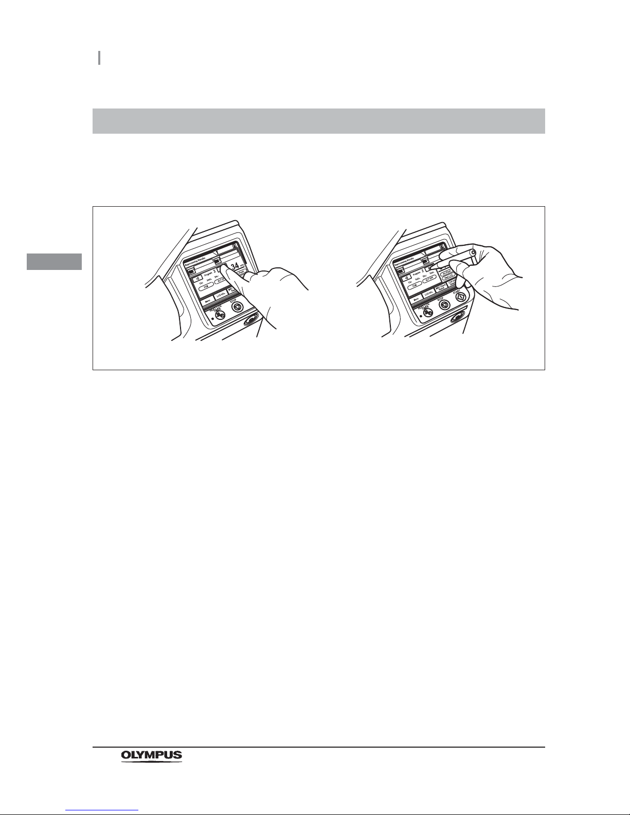
40
3.3 Control panel operation
OER-Elite OPERATION MANUAL
Ch.3
This reprocessor employs a touch screen control panel.
The touch screen should be manipulated by pressing with a finger of the operator or touching with the
provided stylus pen.
Figure 3.8
3.3 Control panel operation
Pressing with a finger of the operator. Touching with the provided stylus pen.
Page 51
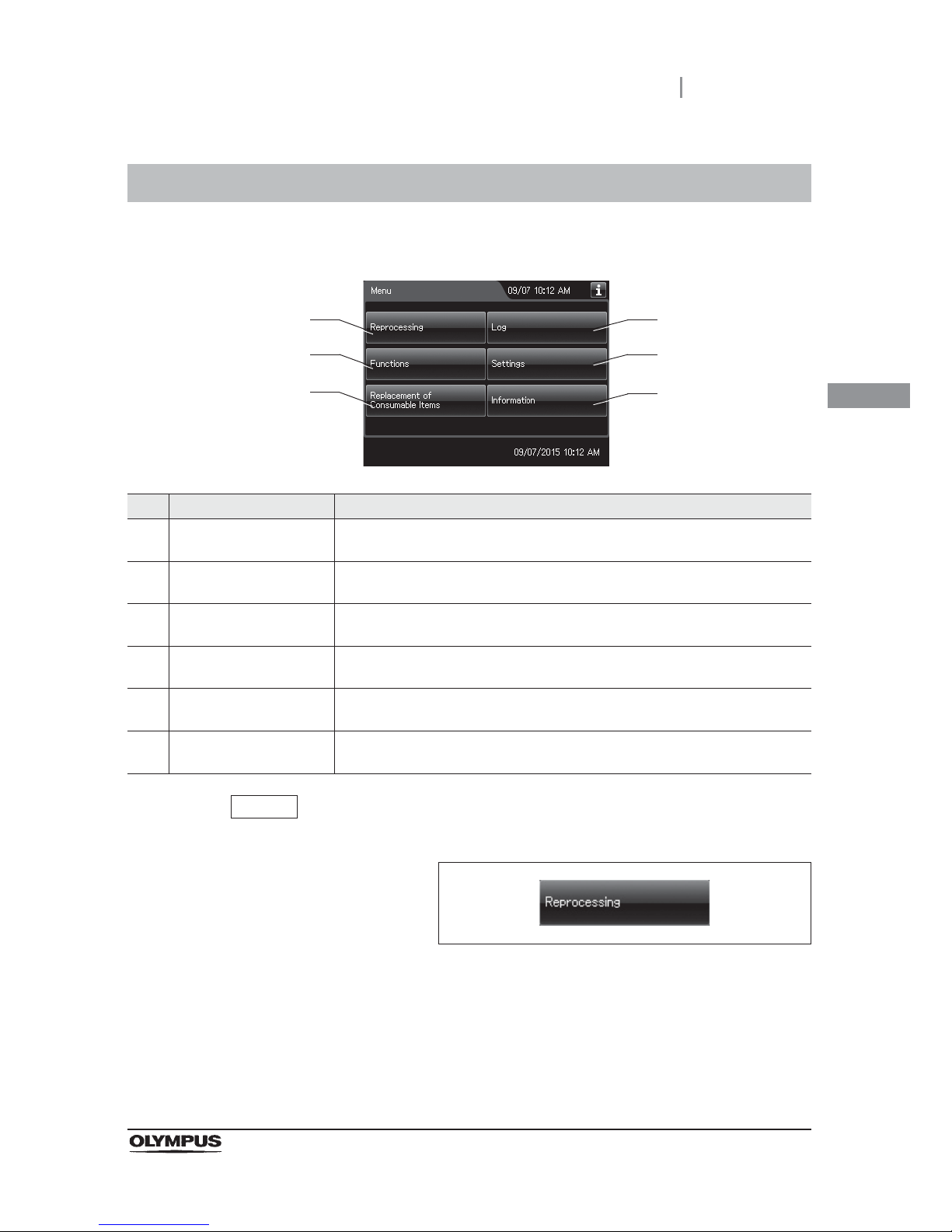
3.4 Menu screen
41
OER-Elite OPERATION MANUAL
Ch.3
In the menu screen, there are six buttons. Select the desired category here.
NOTE
The operational buttons are expressed by a box with gradation.
Figure 3.9
3.4 Menu screen
No. Button Description
1 Reprocessing Press this button to display the Reprocessing Standby screen.
oRefer to Section 6.5, “Basic operation for reprocessing”.
2 Functions Press this button to go to Functions menu.
oRefer to Section 7.1, “Function menu”.
3 Replacement of
Consumable Items
Press this button to go to Replacement of Consumable Items menu.
oRefer to Section 8.1, “Replacement of consumable items menu”.
4 Log Press this button to go to Log menu.
oRefer to Section 11.1, “Log menu”.
5 Settings Press this button to go to Setting menu.
oRefer to Section 4.1, “Setting menu”.
6 Information Press this button to go to Information menu.
oRefer to Chapter 12, “Information Menu Screen”.
1
2
3
4
5
6
Page 52
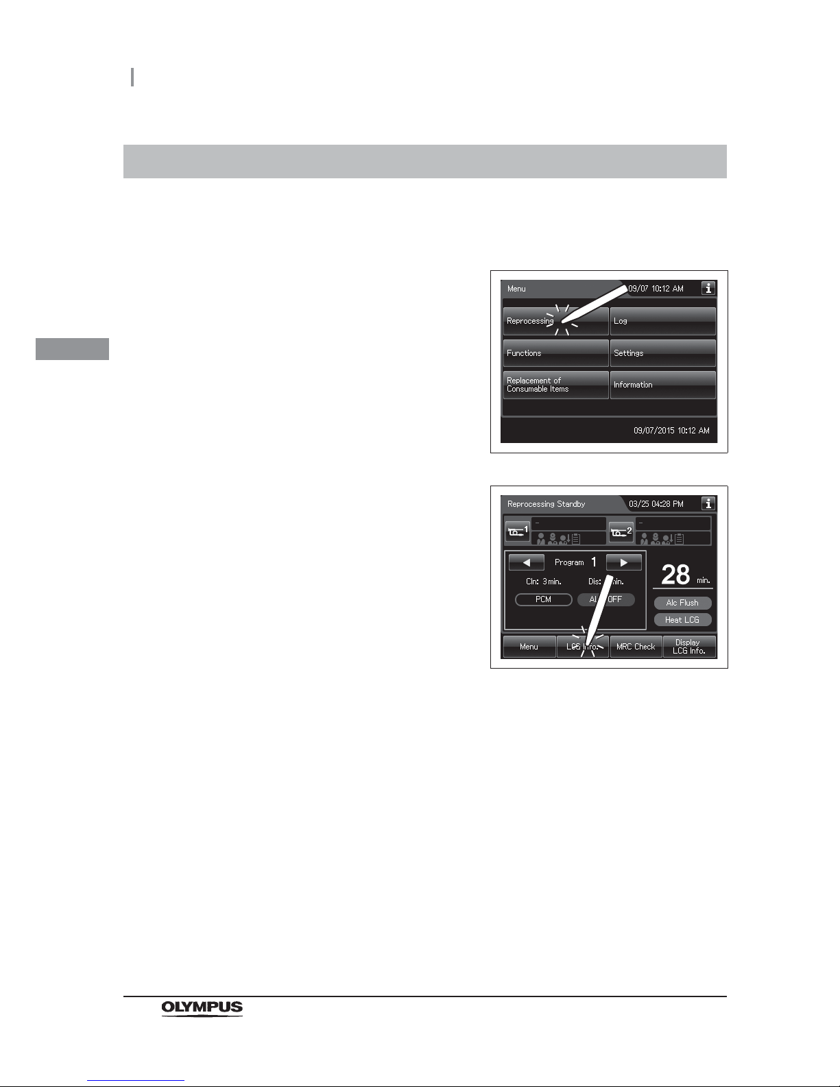
42
3.5 LCG Info. screen
OER-Elite OPERATION MANUAL
Ch.3
This reprocessor can display the information on the disinfectant solution including the temperature and
usage count.
3.5 LCG Info. screen
1 Press the “Reprocessing” button on the touch
screen.
Figure 3.10
2 Press the “LCG Info.” button on the touch
screen.
Figure 3.11
3 The LCG Info. screen pops up.
Page 53
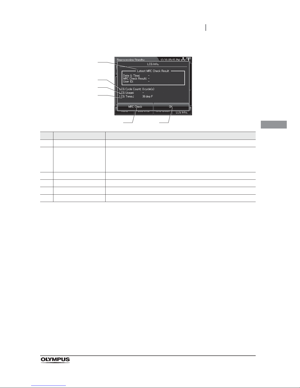
3.5 LCG Info. screen
43
OER-Elite OPERATION MANUAL
Ch.3
No. Item/Button Description
1 Latest MRC Check Result Information on the latest MRC check result.
2 LCG Cycle Count Usage count of the current disinfectant solution. When this setting is activated,
the reprocessor counts the number after each process that uses the disinfectant
solution (e.g. reprocessing, water line disinfection or leaking scope
decontamination) is performed.
3 LCG Usage Number of days the current disinfectant solution has been used.
4 LCG Temp. Current temperature of the disinfectant solution.
5 MRC Check Result Opens the MRC check result input screen.
6 OK Closes the LCG Info. screen.
2
3
4
5 6
1
Page 54
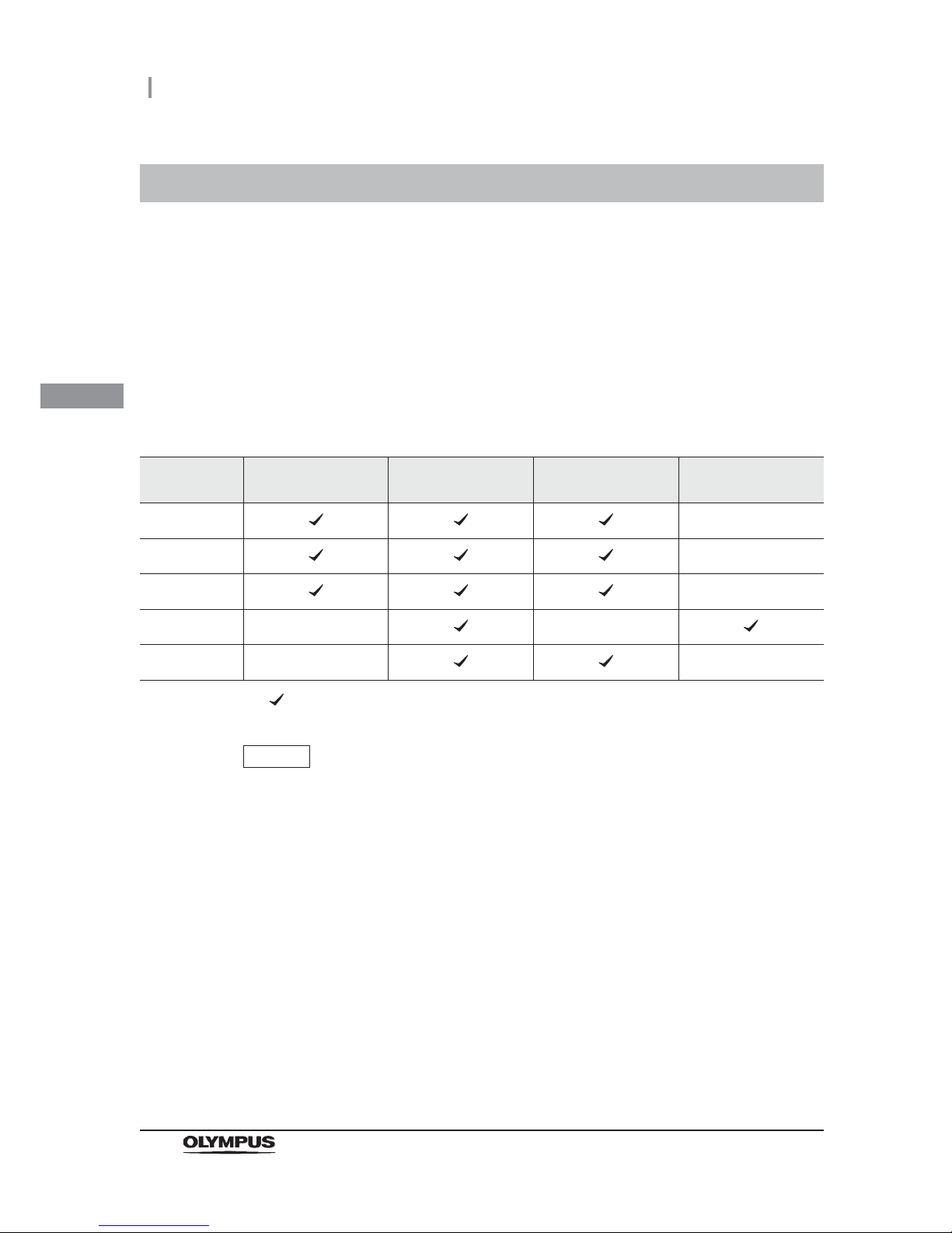
44
3.6 Entering ID
OER-Elite OPERATION MANUAL
Ch.3
Five kinds of IDs can be input, including the scope ID, user ID, physician ID, patient ID and procedure
ID.
The IDs can be input with one of the following four methods. The input methods are variable
depending on the types of IDs.
Input through the RFID reader built into the reprocessor.
Input from the software keyboard displayed on the touch screen.
Recalling ID information registered in advance (Recalling the pre-registered ID).
Input using the optional MAJ-2130 bar code reader.
NOTE
• If the scope ID is input by using the scope ID master card, input by the software
keyboard or input by recalling the pre-registered ID, the “Auto leak test” and
“Channel Monitoring” are disabled.
• When reprocessing endoscope and accessories with no ID tag such as ultrasonic
probes, enter the master ID as the scope ID. If the master ID is entered as the
scope ID, “N/A” is entered as physician, patient and procedure IDs.
• Do not use anything other than the designated ID tag/chip. Otherwise correct data
will not be inputted.
3.6 Entering ID
RFID reader Software keyboard
Recalling the
pre-registered ID
Optional bar code
reader
Scope ID
–
User ID
–
Physician ID
–
Patient ID
––
Procedure ID
– –
Possible – Impossible
Page 55

3.6 Entering ID
45
OER-Elite OPERATION MANUAL
Ch.3
Entering through the RFID reader
WARNING
Be aware that the radio waves emitted from the RFID reader of the reprocessor
may cause medical devices such as pacemakers to malfunction. If any interference
with the equipment is observed, immediately move away from the RFID reader or
set the power switch to OFF. Call your doctor if you do not begin to feel better.
CAUTION
Electromagnetic interference with other devices may reduce the communication
distance of the designated ID tag and cause signals to become unreadable. Try to
take mitigation measures such as keeping other radio frequency emitting or other
energy emitting devices, such as electrosurgical units, away from this reprocessor.
Perform the following operations on a screen that requests an ID input such as the Reprocessing
Standby screen.
Page 56
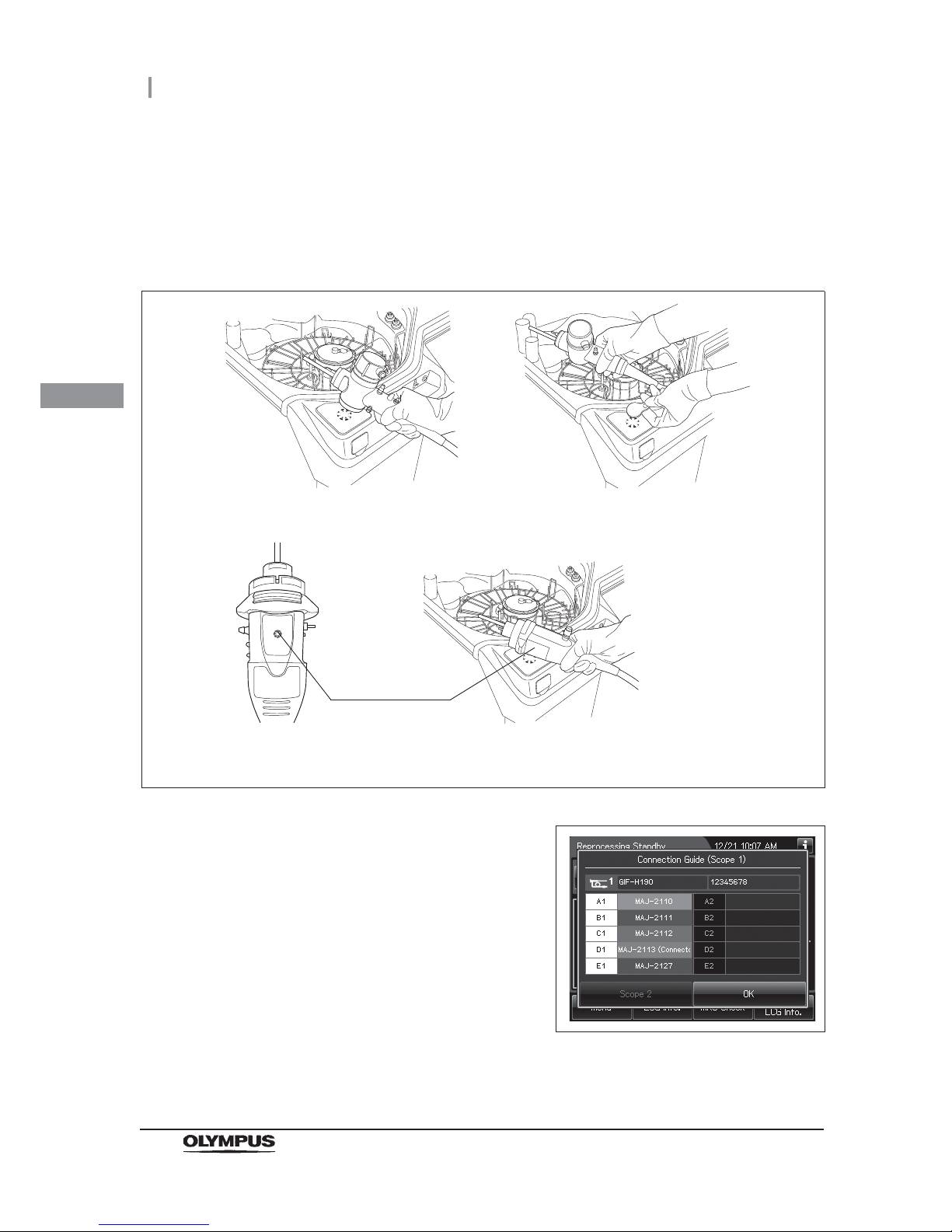
46
3.6 Entering ID
OER-Elite OPERATION MANUAL
Ch.3
Scope ID entry
1 Press the “Reprocessing” button on the Menu Screen.
2 Hold the internal ID endoscope connector or the external ID tag near the RFID reader
on the OER-Elite. A short beep will indicate the tag was read successfully.
Figure 3.12
3 If the connection guide display setting is
activated, when the ID has been read, the
following screen appears.
Figure 3.13
For internal ID endoscope
(For example 180 series endoscope)
For external ID tag
For internal ID endoscope (190
series endoscope
1
)
Scope ID mark
1 190 series endoscopes may not be available in some areas.
Page 57
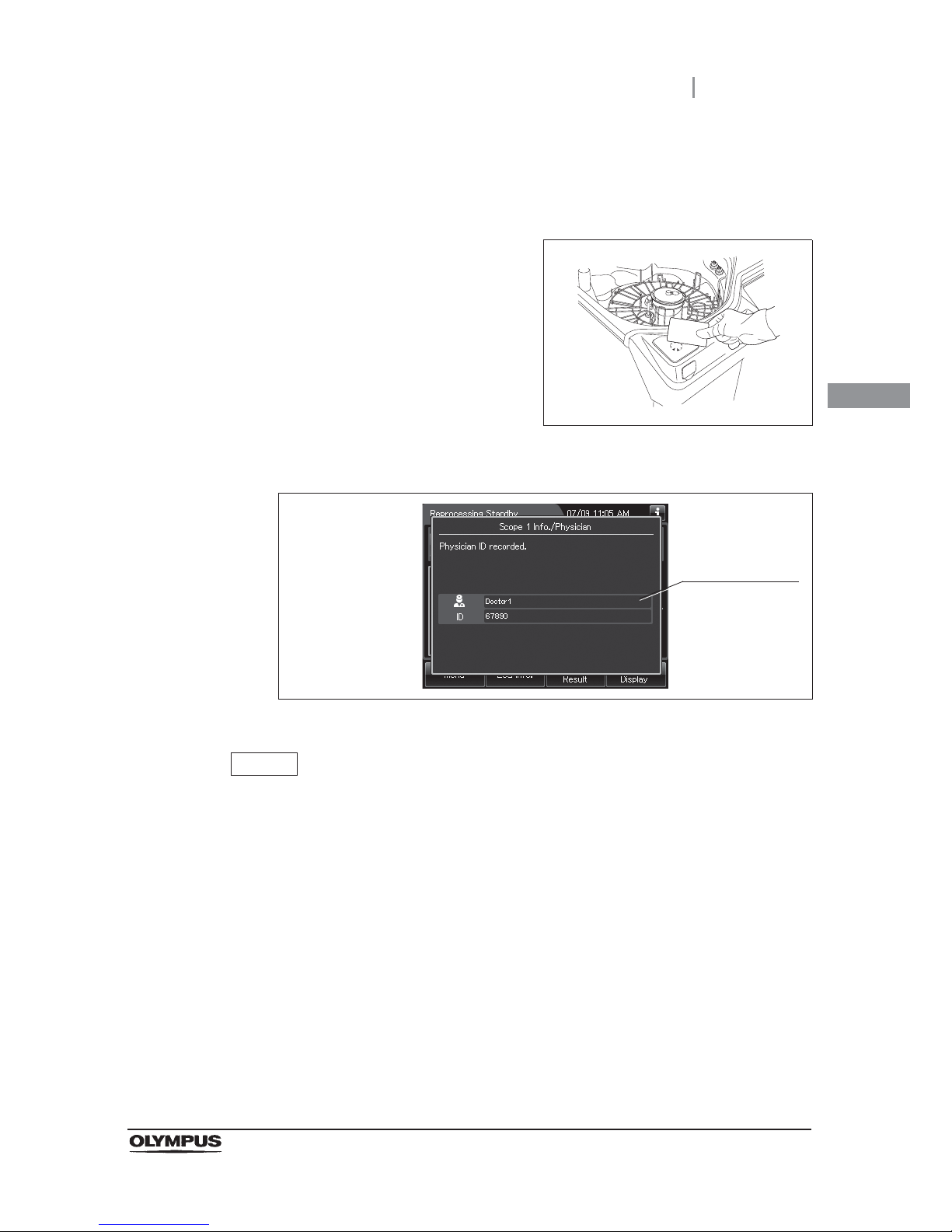
3.6 Entering ID
47
OER-Elite OPERATION MANUAL
Ch.3
User or physician ID entry
NOTE
The user ID (load) and physician ID of second endoscope can be read after reading
the ID of second endoscope.
1 Press the “Reprocessing” button on the Menu screen.
2 Hold the user or physician ID card parallel with
the ID reader section and approach it until a
short beep is generated.
Figure 3.14
3 When the ID has been read, the following screen appears.
Figure 3.15
The information
on the input ID
is displayed.
Page 58
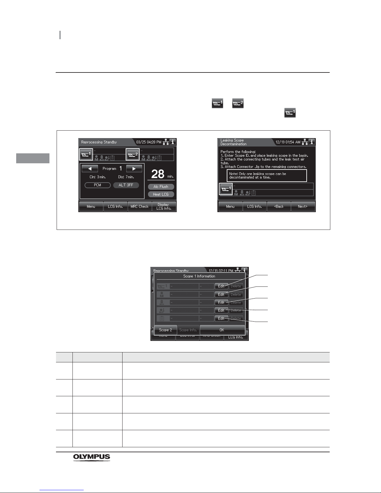
48
3.6 Entering ID
OER-Elite OPERATION MANUAL
Ch.3
Entering by the software keyboard
An ID can be entered by the software keyboard (on-screen) on the touch screen as described below.
1 If it is during the reprocessing process, press or button on the Reprocessing
Standby screen. If it is during the leaking scope decontamination, press button on
the ID input screen.
Figure 3.16
2 Then, the ID select screen is displayed.
No. Button Note
1 “Edit” button of
scope ID
Opens the scope ID list.
2 “Edit” button of
patient ID
Opens the patient ID list.
3 “Edit” button of
physician ID
Opens the physician ID list.
4 “Edit” button of
user ID (load)
Opens the user ID (load) list.
5 “Edit” button of
procedure ID
Opens the procedure ID list.
Reprocessing Leaking scope decontamination
1
2
3
4
5
Page 59
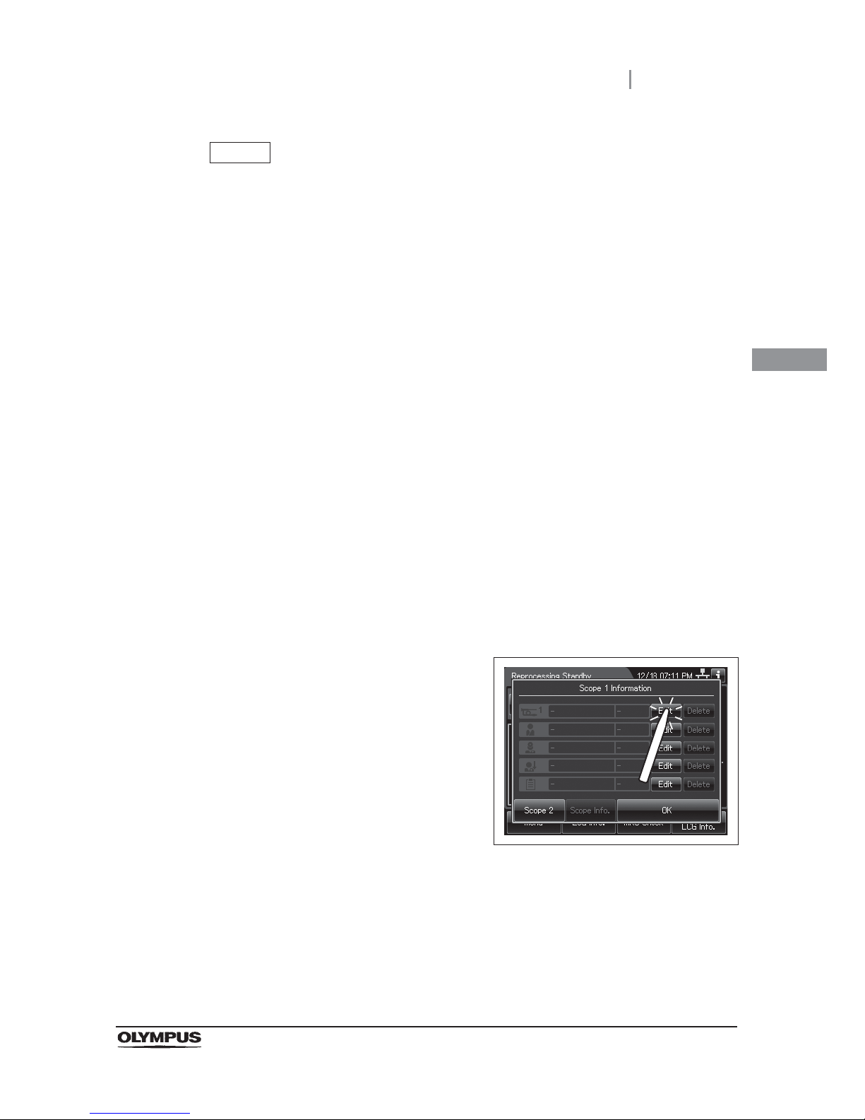
3.6 Entering ID
49
OER-Elite OPERATION MANUAL
Ch.3
NOTE
• When scope ID is entered using the software keyboard, the auto leak test and
channel blockage monitoring functions will not be available. In the manual leak test
function, the scope ID can be entered by the software keyboard. To enter the scope
ID, Press the “Edit” button during the manual leak test. Then, refer to step 2 in
“ Scope ID entry” on page 49.
• In the auto leak test function, the scope ID cannot be entered by the software
keyboard (on-screen). RFID of the endoscope is necessary to perform the auto
leak test.
• When User ID setting of Reprocessing (end of reprocessing) is activated, the user
ID can be entered by the software keyboard (on-screen) at the end of reprocessing.
To enter the user ID, press the “Edit” button at the end of reprocessing. Then, refer
to Step 2 in “ Physician ID, user ID, or procedure ID entry” on page 59. For details
of User ID setting, refer to Section 4.5, “User ID Setting”.
• When user ID setting of “Functions & Replacement of Consumable Items” is
activated, the user ID can be entered by the software keyboard (on-screen) before
starting each function or replacement. To enter the user ID, Press the “Edit” button
during each function or replacement. Then, refer to Step 2 in “ Physician ID, user
ID, or procedure ID entry” on page 59. For details of User ID setting, refer to
Section 4.5, “User ID Setting”.
Scope ID entry
1 Press the “Edit” button of scope ID on the ID
select screen.
Figure 3.17
Page 60
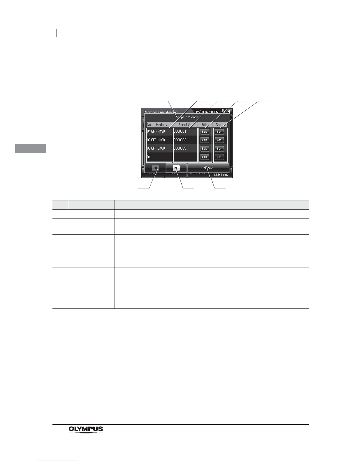
50
3.6 Entering ID
OER-Elite OPERATION MANUAL
Ch.3
2 Then the scope ID list is displayed. When the Scope ID is not listed on the ID list, go
to “(a) Select a Scope ID that is not listed” on page 51. When the Scope ID is listed on
the ID list, go to “(b) Recalling the pre-registered ID” on page 54.
No. Item/Button Note
1 ID type Type of the currently edited ID.
2 Model # Registered model number of the endoscope. These areas are blank if no ID has been
registered.
3 Serial # Registered serial number of the endoscope. These areas are blank if no ID has been
registered.
4 Edit Press one of the buttons to open the ID information edit screen.
5 Set Press one of the buttons to set a registered ID.
6 Previous page
button
Press to return to the previous page. When there is no further page to turn back to, the
button turns gray and becomes unavailable.
7 Next page button Press to go to the next page. When there is no further page to go forward to, the button
turns gray and becomes unavailable.
8 Back Press to close the ID select screen.
1
6 7
2 3
8
4 5
Page 61
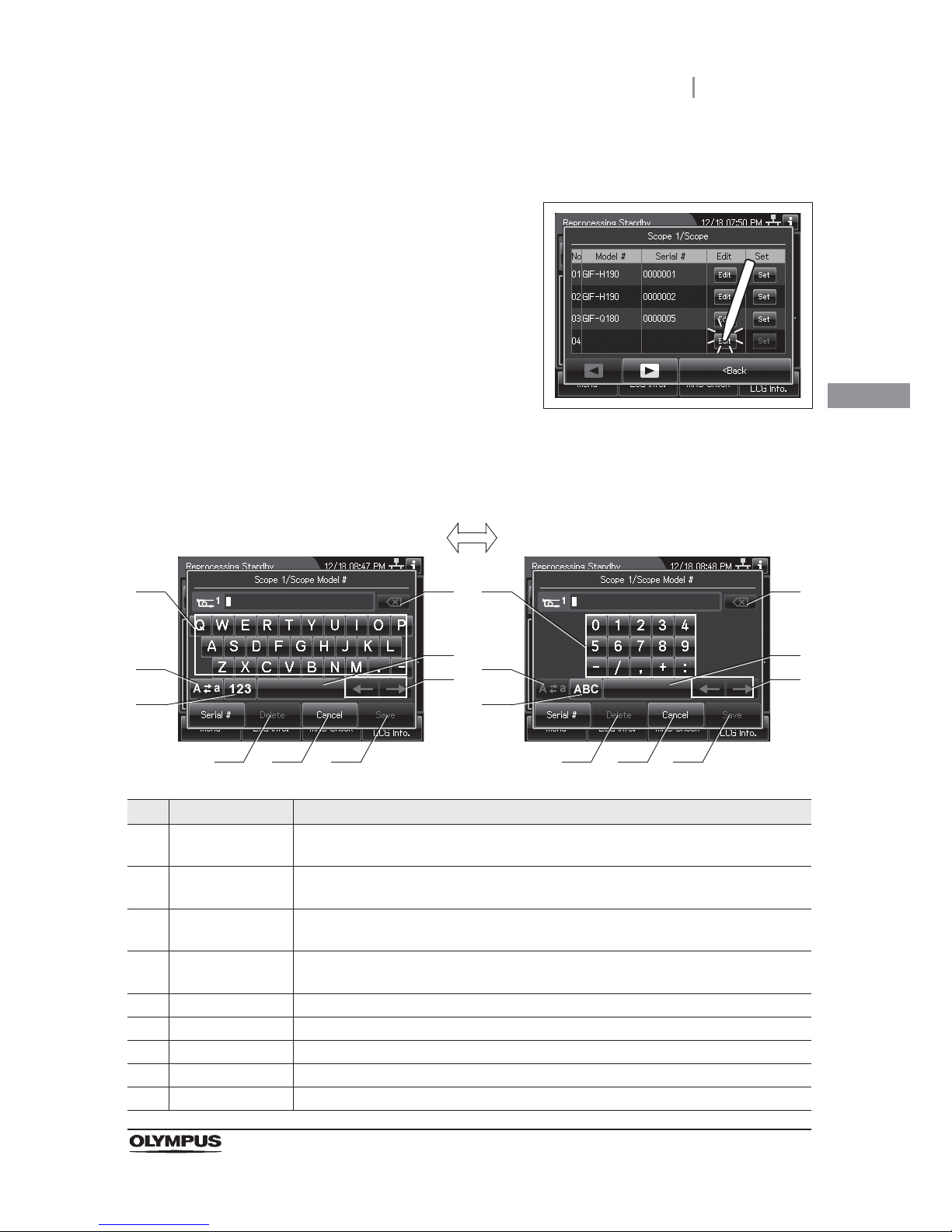
3.6 Entering ID
51
OER-Elite OPERATION MANUAL
Ch.3
(a) Select a Scope ID that is not listed
1 To set a new scope ID, press the “Edit” button
that no ID has been registered. To change the
registered Scope ID, press the “Edit” button of
the Scope ID.
Figure 3.18
2 The software keyboard (on-screen) is opened. Enter the model number of the
endoscope on the software keyboard.
No. Button Note
1 Alphabet/
Numeral key
Enter an alphabet or a numeral.
2 Uppercase/
Lowercase
Press “Uppercase/lowercase” button to switch alphabet character on the software
keyboard (on-screen) between uppercase characters and lowercase characters.
3 Numeric/
Alphabetic
Press “Numeric or Alphabetic” button to switch the input mode between a numeral and
the alphabet.
4 Backspace Press the “Backspace” button to delete the left character of a cursor.
When a cursor is on the left edge, this button turns gray and becomes unavailable.
5 Space Press the “Space” button to insert a space character.
6 Cursor move Press the “Cursor move” button to move the cursor left or right.
7 Delete Press the “Delete” button to delete about all information.
8 Cancel Return to the previous screen without saving the setting value.
9 Save Return to the previous screen and save the entered value.
41
2
3
5
6
8 9
41
2
3
5
6
8 9
Alphabet input Numeral input
7 7
Page 62
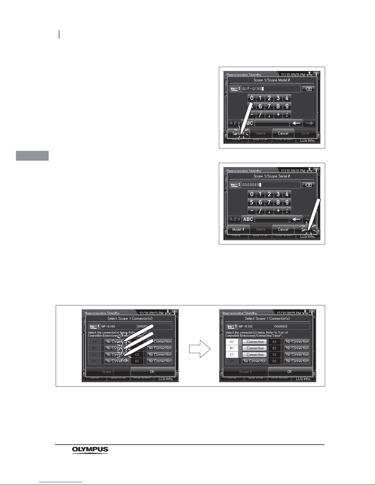
52
3.6 Entering ID
OER-Elite OPERATION MANUAL
Ch.3
3 Press the “Serial #” button on the software
keyboard.
Figure 3.19
4 Enter the serial number of the endoscope.
Press the “Save” button, then the scope ID was
set to the reprocessing process.
Figure 3.20
5 The connection information screen is displayed on the touch screen. Connect the
suitable connecting tubes according to the “List of Compatible
Endoscopes/Connecting Tubes <OER-Elite>”, then press the “No Connection”
buttons corresponding to the reprocessing basin connectors to which the connecting
tubes are connected. The “No Connection” indicator will now change to “Connection”.
Figure 3.21
Page 63
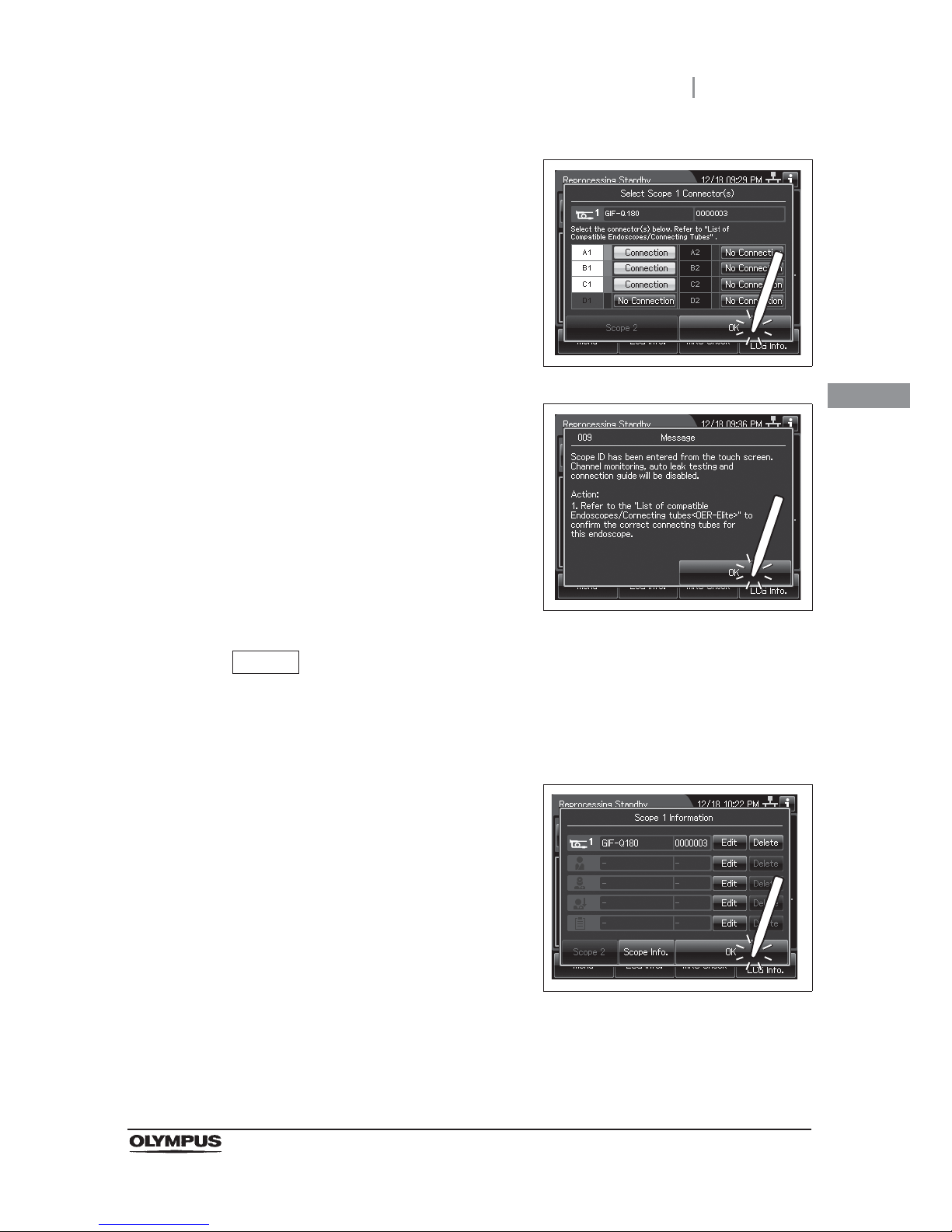
3.6 Entering ID
53
OER-Elite OPERATION MANUAL
Ch.3
6 Press the “OK” button.
Figure 3.22
7 The following message is displayed. After
reading the message, Press the “OK” button
again.
Figure 3.23
NOTE
When the “Manual Cleaning and Leak Test Setting” is activated, select the manual
cleaning and leak testing results after Step 7. For detail, refer to “ Input results of
manual cleaning and leak test of second endoscope” on page 214.
8 Once the scope ID is entered, the ID select
screen appears. To go back to the reprocessing
standby screen, press “OK” button.
Figure 3.24
Page 64
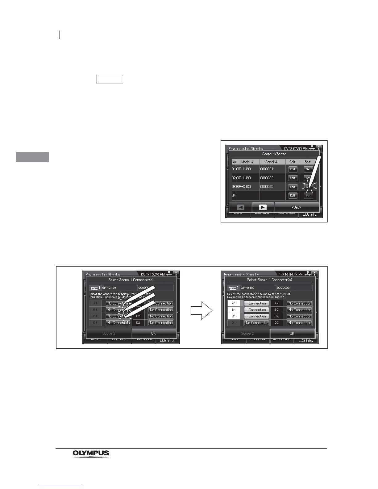
54
3.6 Entering ID
OER-Elite OPERATION MANUAL
Ch.3
(b) Recalling the pre-registered ID
NOTE
• The ID edited on “(a) Select a Scope ID that is not listed” on page 51 is registered
to the ID list.
• The ID list can be edited on the list management function. For detail, refer to
Section 12.3, “List management”.
1 Press the “Set” button for the ID to be recalled.
Figure 3.25
2 On the Connection information screen, Press the “No Connection” buttons
corresponding to the reprocessing basin connectors to which the connecting tubes
are connected. The “No Connection” indicator will now change to “Connection”.
Figure 3.26
Page 65
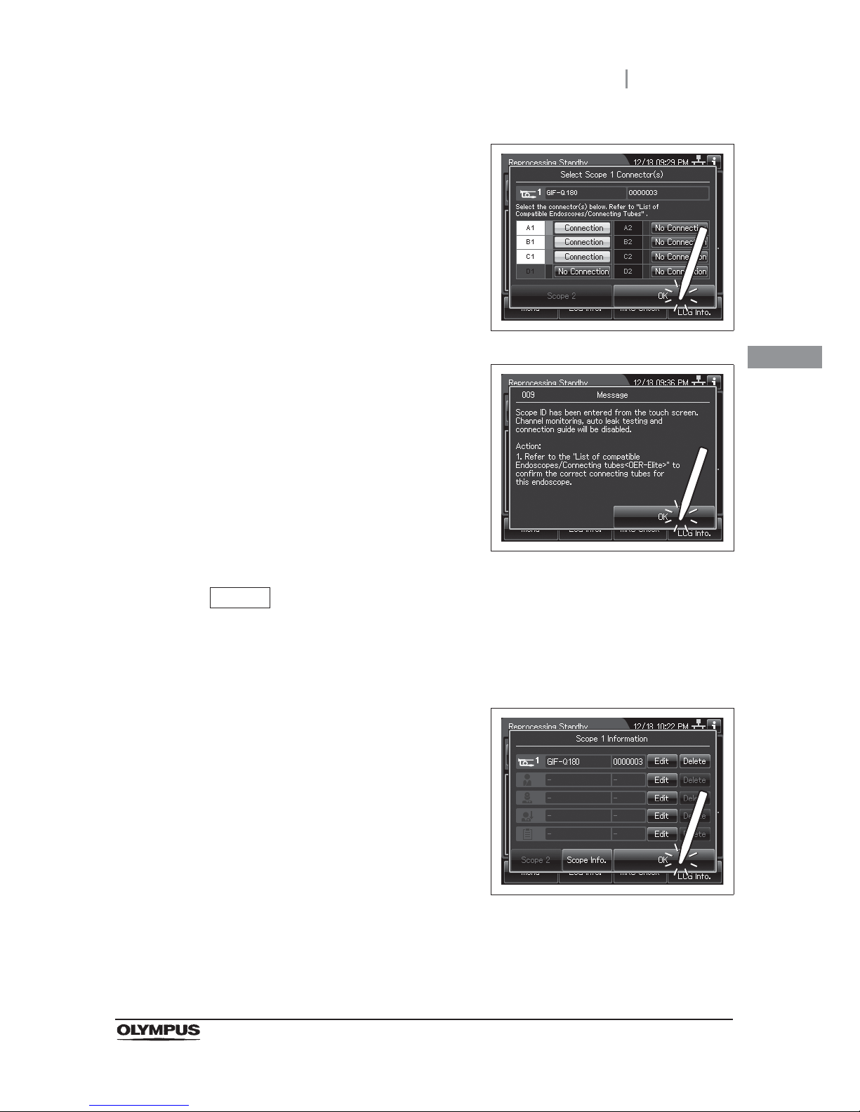
3.6 Entering ID
55
OER-Elite OPERATION MANUAL
Ch.3
3 Press the “OK” button.
Figure 3.27
4 The following message is displayed. After
reading the message, Press the “OK” button
again.
Figure 3.28
NOTE
When the “Manual Cleaning and Leak Test Setting” is activated, select the manual
cleaning and leak testing results after Step 4. For detail, refer to “ Input results of
manual cleaning and leak test of second endoscope” on page 214.
5 When the scope ID is completed to enter, the
ID select screen appears.
Figure 3.29
Page 66
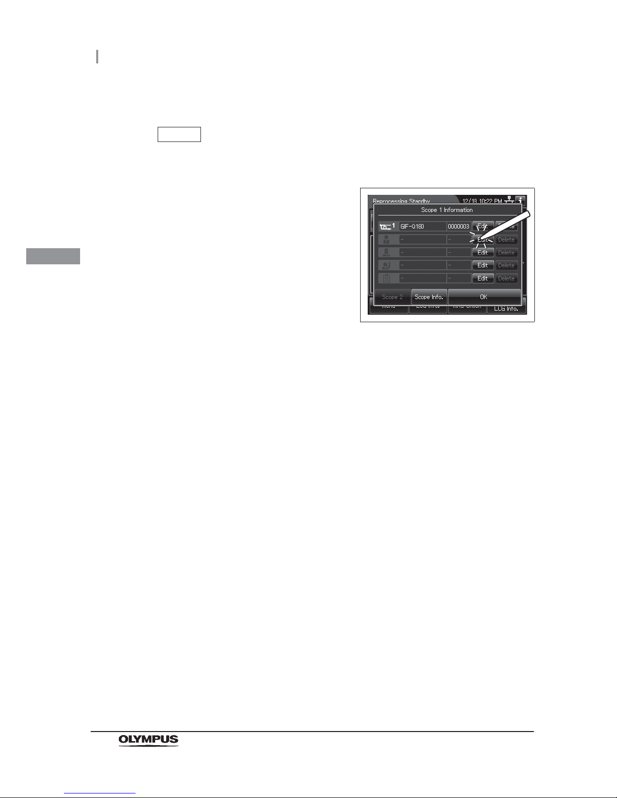
56
3.6 Entering ID
OER-Elite OPERATION MANUAL
Ch.3
Patient ID entry
NOTE
When the patient ID setting is not activated, patient ID cannot be entered.
1 Press the “Edit” button of the patient ID on the
ID select screen.
Figure 3.30
Page 67
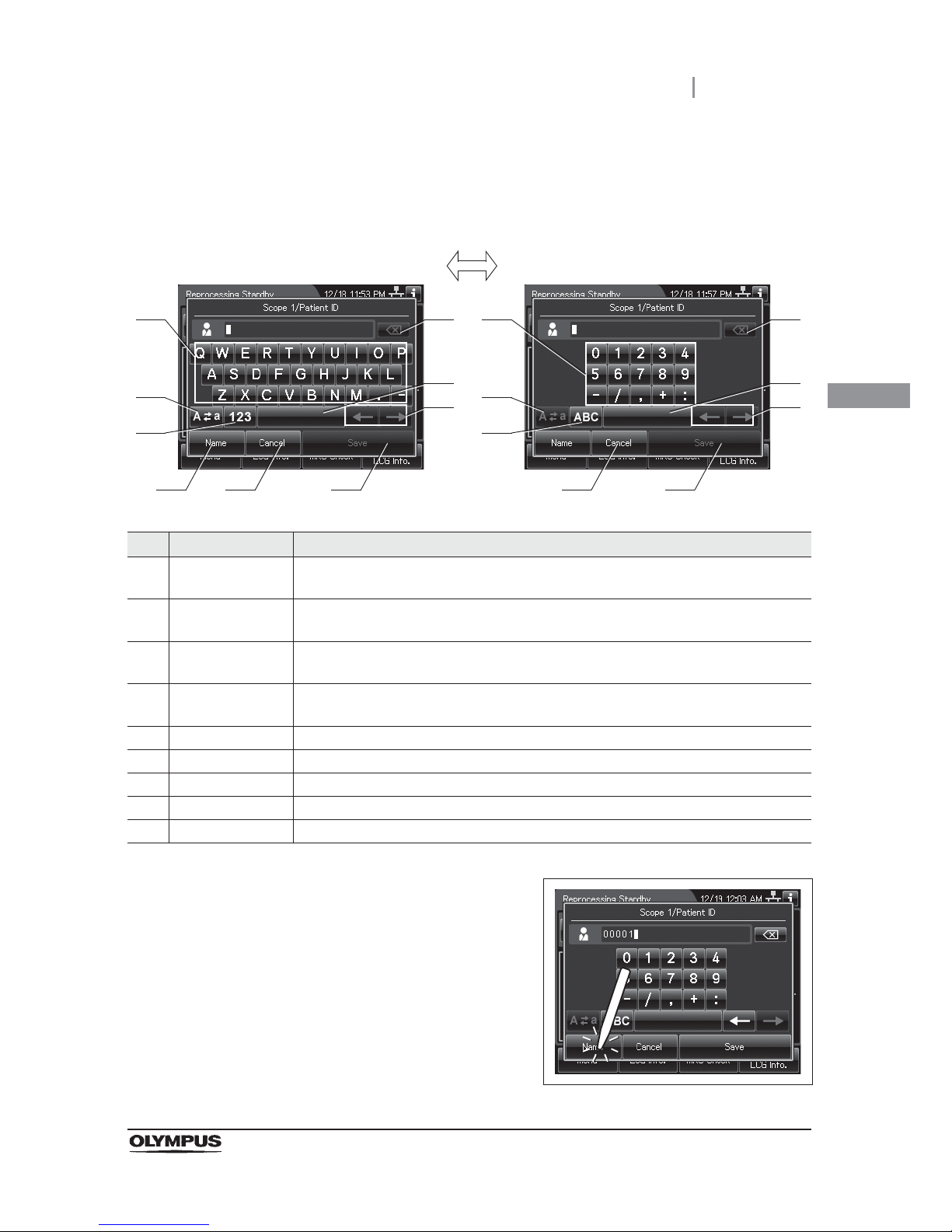
3.6 Entering ID
57
OER-Elite OPERATION MANUAL
Ch.3
2 The software keyboard (on-screen) is opened. Enter the ID number of the patient on
the software keyboard (on-screen).
No. Button Note
1 Alphabet/
Numeral key
Enter an alphabet or a numeral.
2 Uppercase/
Lowercase
Press “Uppercase/lowercase” button to switch alphabet character on the soft keyboard
between uppercase characters and lowercase characters.
3 Numeric/
Alphabetic
Press “Numeric or Alphabetic” button to switch the input mode between a numeral and
the alphabet.
4 Backspace Press the “Backspace” button to delete the left character of a cursor.
When a cursor is on the left edge, this button turns gray and becomes unavailable.
5 Space button Press the “Space” button to insert a space character.
6 Cursor move Press the cursor move button to move the cursor left or right.
7 Name Press “Name or ID” button to switch the input mode between a Name and an ID.
8 Cancel Return to the previous screen without saving the setting value.
9 Save Return to the previous screen and save the entered value.
3 Press the “Name” button.
Figure 3.31
41
2
3
5
6
7 9
41
2
3
5
6
8 9
Alphabet input Numeral input
8
Page 68
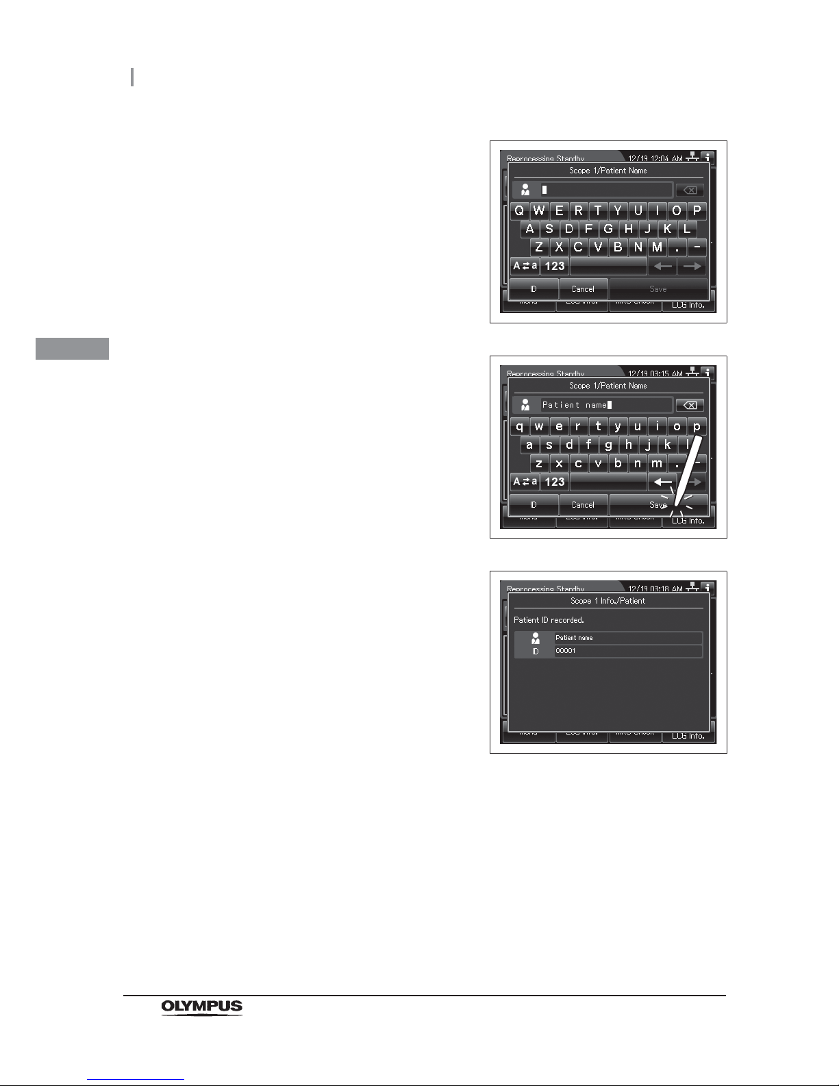
58
3.6 Entering ID
OER-Elite OPERATION MANUAL
Ch.3
4 Enter the patient name.
Figure 3.32
5 Press the “Save” button.
Figure 3.33
6 When the patient ID is completed to enter, the
following screen appears.
Figure 3.34
Page 69
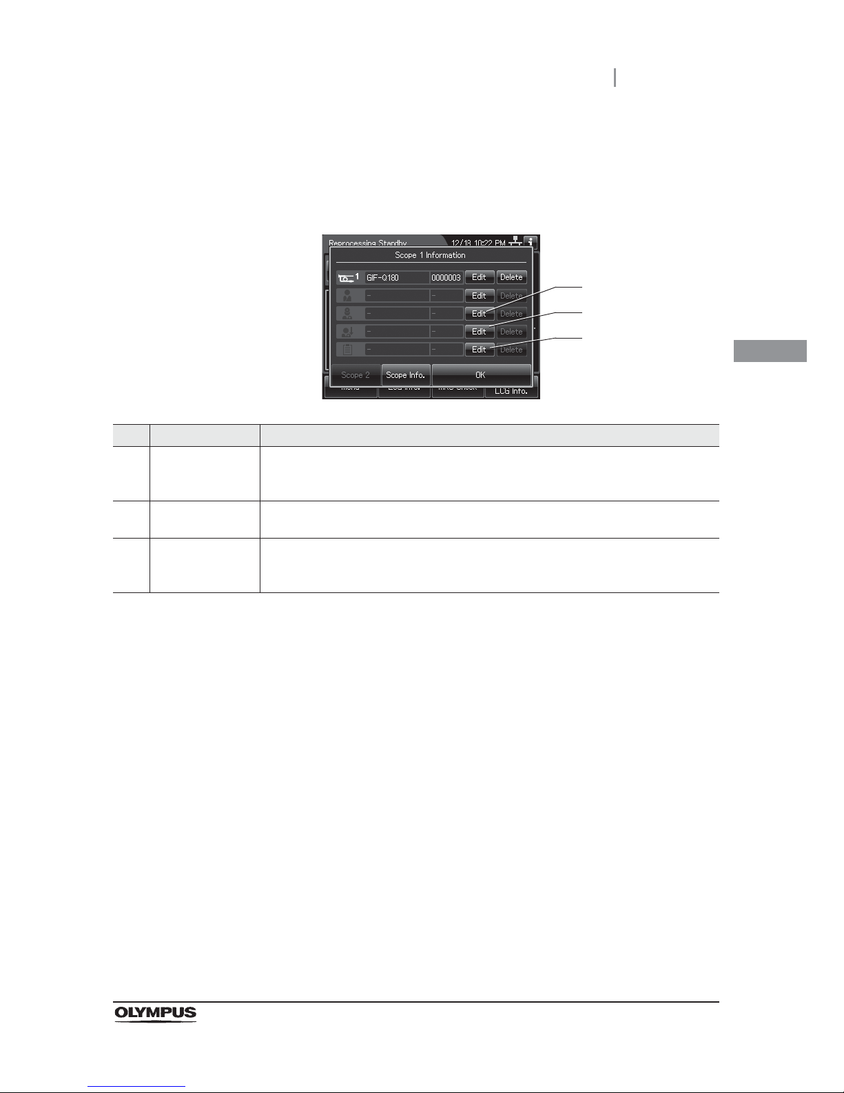
3.6 Entering ID
59
OER-Elite OPERATION MANUAL
Ch.3
Physician ID, user ID, or procedure ID entry
1 Press the “Edit” button to enter each ID on the ID select screen.
No. Button Note
1 Edit physician ID
button
Opens the physician ID list. When the physician ID setting is not activated, item of the
physician ID is not displayed. For physician ID setting, refer to Section 4.6, “Physician ID
setting”.
2 Edit user ID button Opens the user ID list. When the user ID setting is not activated, item of the user ID is
not displayed. For user ID setting, refer to Section 4.5, “User ID Setting”.
3 Edit procedure ID
button
Opens the procedure ID list. When the procedure ID setting is not activated, item of the
procedure ID is not displayed. For procedure ID setting, refer to Section 4.9, “Procedure
ID setting”.
1
2
3
Page 70
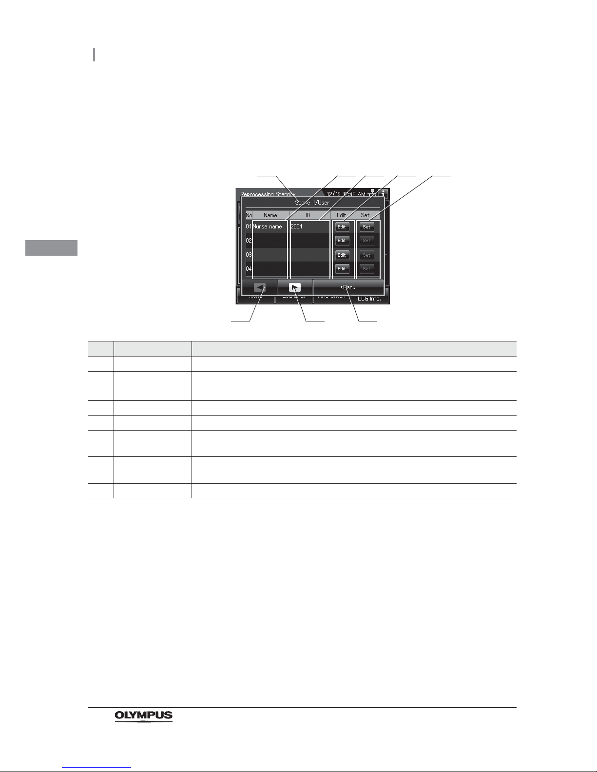
60
3.6 Entering ID
OER-Elite OPERATION MANUAL
Ch.3
2 Then the ID list is displayed. When the ID is not listed on the ID list, go to “(a) Select
each ID that is not listed” on page 61. When the Scope ID is listed on the ID list, go to
“(b) Recalling the pre-registered ID” on page 63.
No. Item/Button Note
1 ID type Type of the currently edited ID.
2 Name Name of the registered IDs. These areas are blank if no ID has been registered.
3 ID ID number of registered IDs. These areas are blank if no ID has been registered.
4 Edit buttons Press one of the buttons to open the ID information edit screen.
5 Set buttons Press one of the buttons to set a registered ID.
6 Previous page
button
Press to return to the previous page. When there is no further page to turn back to, the
button turns gray and becomes unavailable.
7 Next page button Press to go to the next page. When there is no further page to go forward to, the button
turns gray and becomes unavailable.
8 Back Press to close the ID select screen.
1
6 7
2 3
8
4 5
Page 71
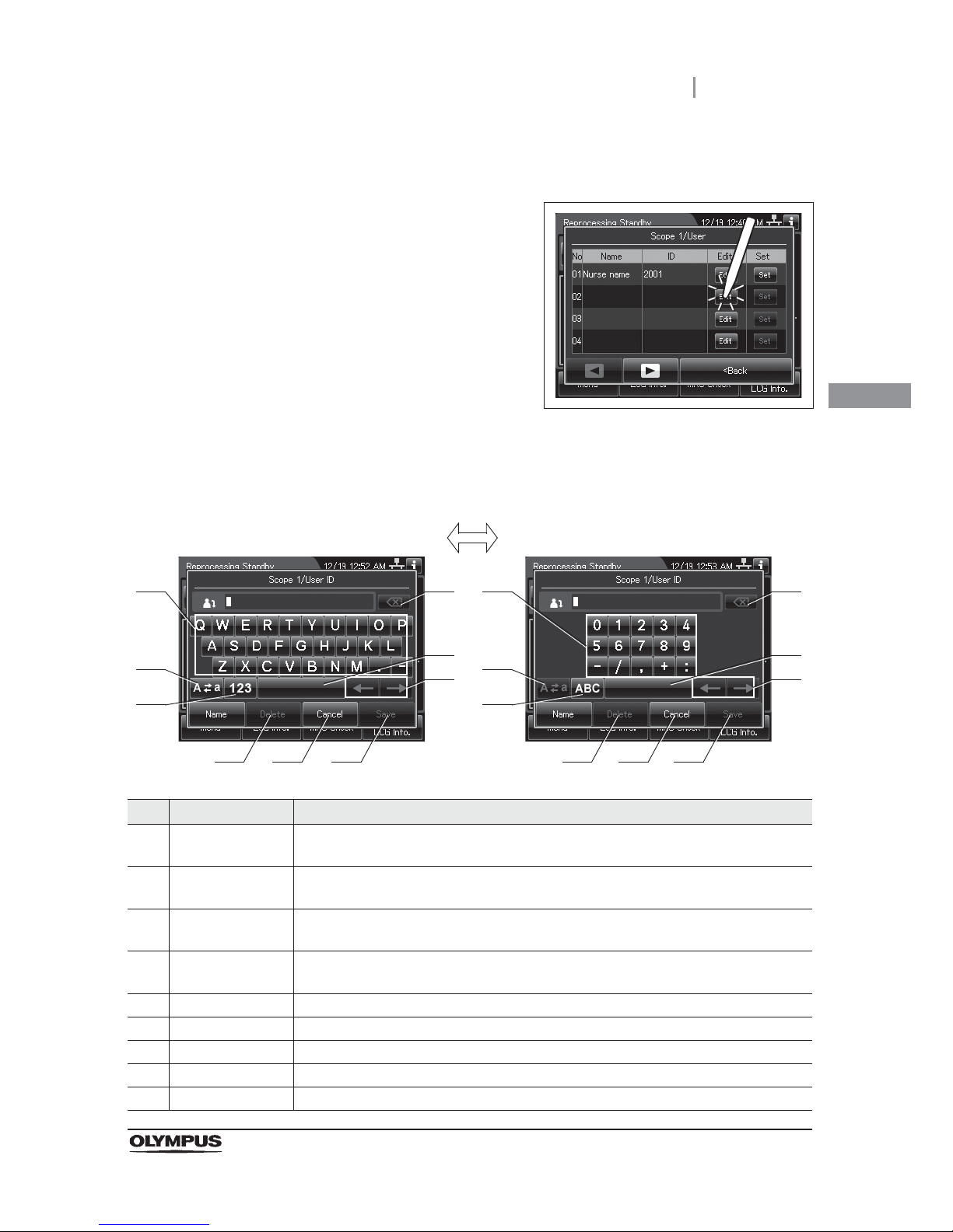
3.6 Entering ID
61
OER-Elite OPERATION MANUAL
Ch.3
(a) Select each ID that is not listed
1 Press the “Edit” button that no ID has been
registered.
Figure 3.35
2 The software keyboard (on-screen) is opened. Enter the ID number of the physician,
user, or procedure on the software keyboard (on-screen).
No. Button Note
1 Alphabet/
Numeral key
Enter an alphabet or a numeral.
2 Uppercase/
Lowercase
Press “Uppercase/lowercase” button to switch alphabet character on the soft keyboard
between uppercase characters and lowercase characters.
3 Numeric/
Alphabetic
Press “Numeric or Alphabetic” button to switch the input mode between a numeral and
the alphabet.
4 Backspace Press the “Backspace” button to delete the left character of a cursor.
When a cursor is on the left edge, this button turns gray and becomes unavailable.
5 Space Press the “Space” button to insert a space character.
6 Cursor move Press the “Cursor move” button to move the cursor left or right.
7 Delete Press the “Delete” button to delete about all information.
8 Cancel Return to the previous screen without saving the setting value.
9 Save Return to the previous screen and save the entered value.
41
2
3
5
6
8 9
41
2
3
5
6
8 9
Alphabet input Numeral input
7 7
Page 72
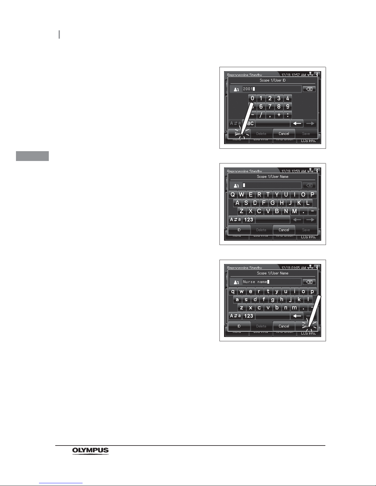
62
3.6 Entering ID
OER-Elite OPERATION MANUAL
Ch.3
3 Press the “Name” button.
Figure 3.36
4 Enter the physician, user, or procedure name.
Figure 3.37
5 Press the “Save” button.
Figure 3.38
Page 73
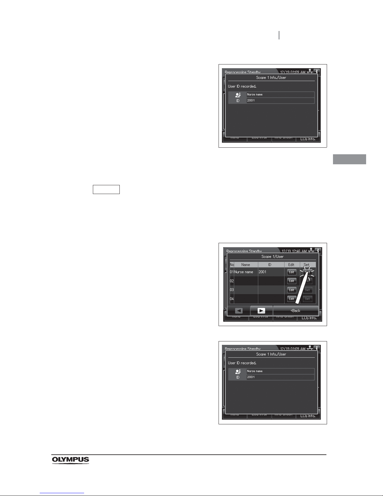
3.6 Entering ID
63
OER-Elite OPERATION MANUAL
Ch.3
(b) Recalling the pre-registered ID
NOTE
• The ID edited on “(a) Select each ID that is not listed” is registered to the ID list.
• The ID list can be edited on the list management function. For detail, refer to
Section 12.3 “List management”.
6 When the ID is completed to enter, the
following screen appears.
Figure 3.39
1 Press the “Set” button for the ID to be recalled.
Figure 3.40
2 When the ID is completed to enter, the
following screen appears.
Figure 3.41
Page 74
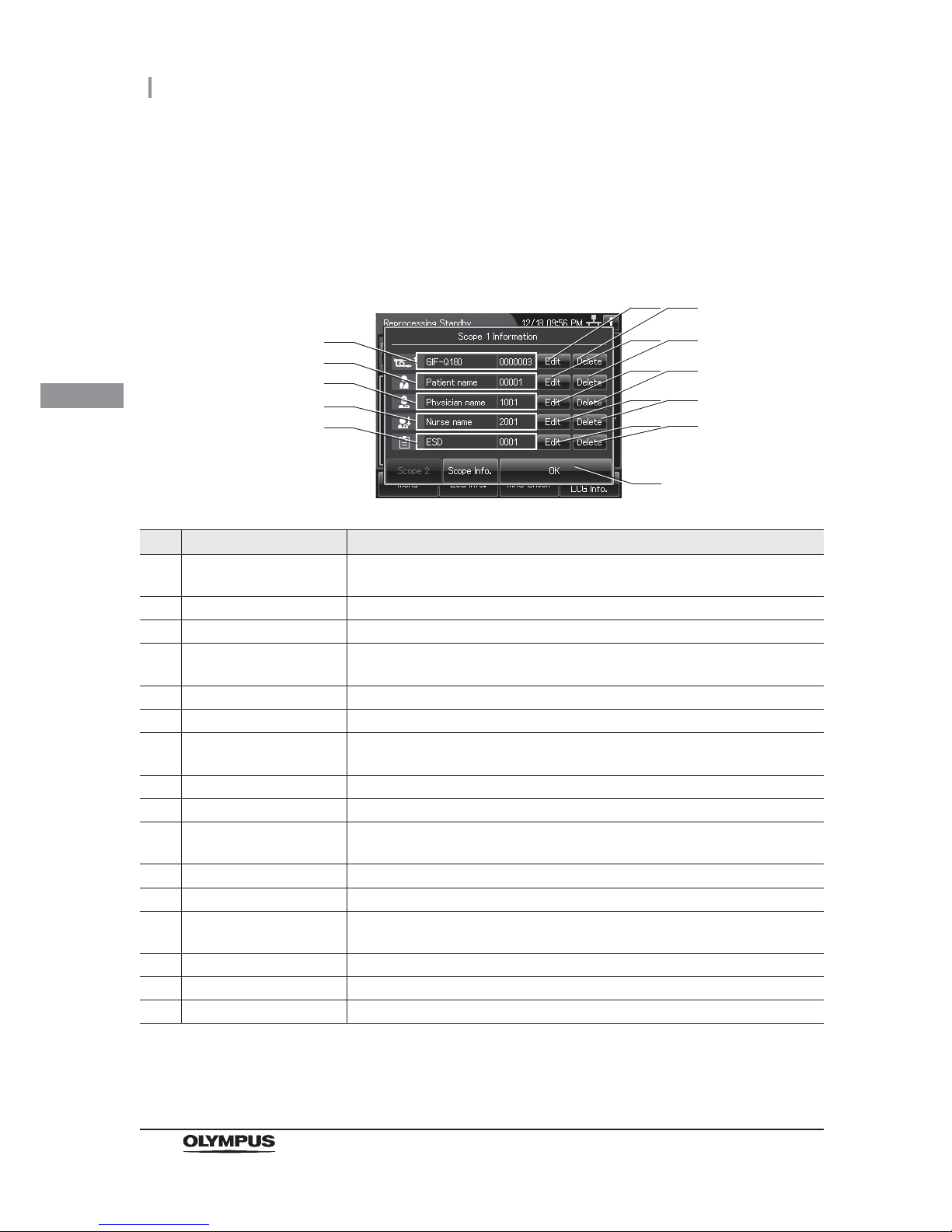
64
3.6 Entering ID
OER-Elite OPERATION MANUAL
Ch.3
Confirmation of the input ID
1 Open the ID select screen.
2 Confirm each ID information.
No. Item/Button Note
1 View Scope ID information Displays the scope ID information (endoscope type and serial number).
This area is blank when no scope ID has been input.
2 Edit Scope ID button Opens the scope ID list to modify.
3 Delete Scope ID button Deletes the input scope ID information.
4 View Patient ID
information
Displays the patient ID information (patient name and ID number).
This area is blank when no patient ID has been input.
5 Edit Patient ID button Opens the patient ID list to modify.
6 Delete Patient ID button Deletes the input patient ID information.
7 View Physician ID
information
Displays the physician ID information (physician name and ID number).
This area is blank when no physician ID has been input.
8 Edit Physician ID button Opens the physician ID list to modify.
9 Delete Physician ID button Deletes the input physician ID information.
10 View user ID information Displays the user ID (load) information (user name and ID number).
This area is blank when no user ID has been input.
11 Edit user ID button Opens the user ID list to modify.
12 Delete user ID button Deletes the input user ID information.
13 View procedure ID
information
Displays the procedure ID information (procedure name and ID number).
This area is blank when no procedure ID has been input.
14 Edit procedure ID button Opens the procedure ID list to modify.
15 Delete procedure ID button Deletes the input procedure ID information.
16 OK button Returns to the Reprocessing standby screen.
1
16
5
4
7
10
13
6
8 9
11 12
14 15
2 3
Page 75

3.6 Entering ID
65
OER-Elite OPERATION MANUAL
Ch.3
Entering the patient ID by the optional bar code
To input the patient ID from a bar code, it is required to connect the optional MAJ-2130 bar code
reader.
For the installation of the bar code reader, refer to the Instructions - Installation Manual for this
reprocessor and the Instructions for the MAJ-2130 bar code reader.
CAUTION
Do not connect anything other than the designated bar code reader to the bar code
port. Otherwise, the IDs may not be read out correctly or the instrument may
malfunction.
NOTE
• A patient ID can be input by either bar cord reader or software keyboard
(on-screen), but a patient name can be input only by the software keyboard. It is
possible to input the patient name by software keyboard (on-screen) after entering
the patient ID by the bar code reader.
• The OER-Elite can read the top 23 characters of each bar code. When the bar
code contains data other than patient data, the reprocessor reads all of
23 characters including data other than the patient data that a bar code has.
• Do not alter the settings of the bar code reader. It has been set to the optimum
settings for combined use with this reprocessor. If the Settings are altered, it may
be impossible to read the bar code, contact Olympus.
Page 76

66
3.6 Entering ID
OER-Elite OPERATION MANUAL
Ch.3
Readable bar code standards
The optional MAJ-2130 bar code reader can read below as a bar cord standards.
UPC/EAN
Code 128
GS1-128
Code 39
Trioptic Code 39
Code 93
Code 11
Interleaved 2 of 5
Discrete 2 of 5
Codabar
MSI
Chinese 2 of 5
Matrix 2 of 5
Korean 3 of 5
Inverse 1D
GS1 DataBar
Composite Codes
Page 77
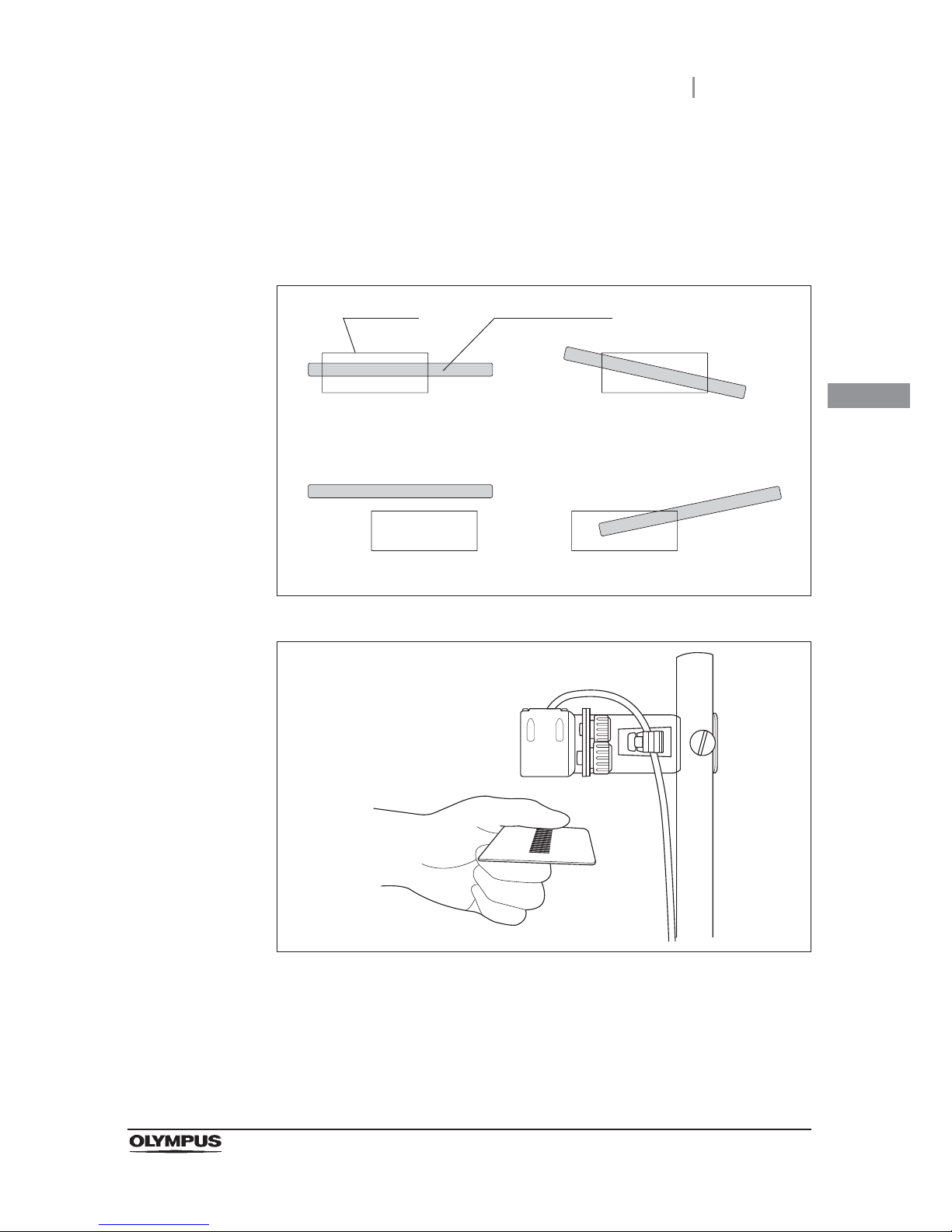
3.6 Entering ID
67
OER-Elite OPERATION MANUAL
Ch.3
Scanning area of the bar code reader
When the bar code reader scans a bar code, the bar code reader projects a green aiming
pattern. The scanning pattern of the bar code reader is formed by the aiming pattern. When the
entire bar code does not cross the scanning pattern, the bar code reader cannot scan the entire
bar code. For how to install the bar code reader (for example setting), refer to Figure 3.43.
Figure 3.42
Figure 3.43
Suitable examples
Unsuitable examples
Aiming pattern
Bar code
Page 78
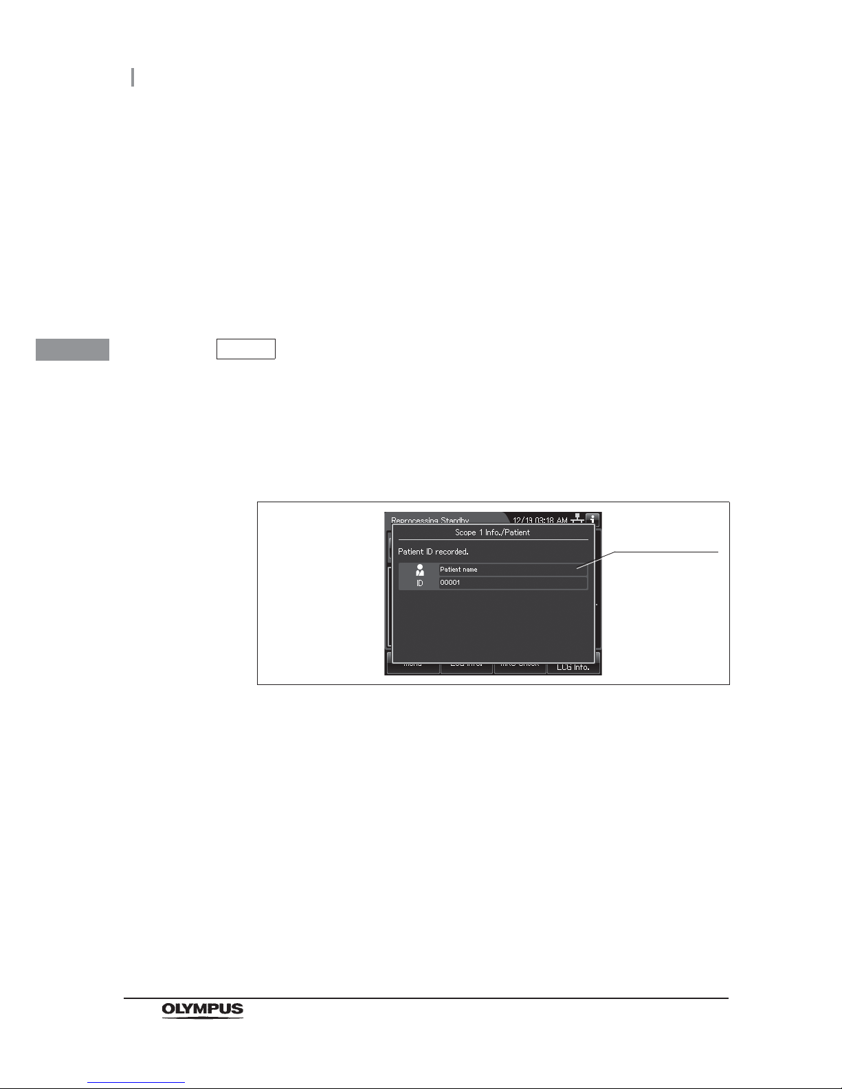
68
3.6 Entering ID
OER-Elite OPERATION MANUAL
Ch.3
Reading a bar code
1 Press the “Reprocessing” button on the touch screen.
2 Place the bar code under the bar code reader to read the bar code and adjust the
distance between them so that the entire bar code is within the scanning area of the
bar code reader. When the bar code reader succeeds in scanning of the bar code, the
bar code reader sounds a short beep. If the bar code reader does not sound a short
beep, correct problems in reference to the instruction manual for the bar code reader
MAJ-2130 or Section 13.2, “Troubleshooting guide”.
NOTE
If the bar code reader does not sound a short beep, correct problems in reference
to the instruction manual for the bar code reader MAJ-2130 and Section 13.2,
“Troubleshooting guide”.
3 The touch screen displays data scanning form bar code as shown in the following
figure. Check if the patient ID matches the actual patient information.
Figure 3.44
Screen of
information on
the input ID
Page 79

3.7 Checking the MRC level and entering the check result
69
OER-Elite OPERATION MANUAL
Ch.3
Before starting any of the following processes, be sure to check that the concentration of the
disinfectant solution is no less than the Minimum Recommended Concentration (MRC). If the
concentration is below the recommended minimum concentration or the shelf life of the disinfectant
solution has expired, replace the disinfectant solution. The result of MRC can be recorded with the
reprocessor.
Reprocessing
Leaking scope decontamination
Water line disinfection
Self-disinfection & Water sampling
Detergent line disinfection
Alcohol line disinfection
WARNING
• The use life of the disinfectant solution may vary depending on many factors,
including storage conditions, and the temperature of the environment where the
reprocessor is installed. Routinely check the concentration of the disinfectant
solution with the test strip before performing endoscope disinfection. If this check is
not performed, the disinfection process may be ineffective. Replace the disinfectant
solution when it fails to meet the minimum recommended concentration or beyond
the specified use life.
• Before handling the disinfectant solution, read the SDS and instructions for use of
the disinfectant solution carefully, get fully accustomed to the contents, and use the
disinfectant solution as instructed. Be sure to fully understand what to do if the
disinfectant solution comes in contact with your skin and eyes.
• When handling the disinfectant solution, wear appropriate personal protective
equipment. Avoid direct physical contact and inhalation of vapors. If any
disinfectant solution gets in your eyes, immediately rinse with a large amount of
fresh water and then consult a medical specialist. Personal protective equipment
includes eyewear, face mask, moisture-resistant clothing, and chemical-resistant
gloves that fit properly and are long enough so that your skin and eyes is not
exposed. All personal protective equipment should be inspected before use and
replaced periodically. If personal protective gear is damaged or defective in
anyway, do not handle hazardous chemicals and refer to the facility policies.
3.7 Checking the MRC level and entering the check
result
Page 80

70
3.7 Checking the MRC level and entering the check result
OER-Elite OPERATION MANUAL
Ch.3
Required items
Table 3.2
NOTE
For the usable test strips, refer to Section 2.8, “Consumable accessories
(Optional)”.
Checking the MRC level
WARNING
Since the period of validity of the disinfectant solution varies depending on multiple
factors including the storage condition and the environmental temperature of the
reprocessor’s installation location, be sure to check the concentration of the
disinfectant solution before reprocessing endoscopes. If the concentration is below
the recommended minimum concentration or the validity date specified for the
disinfectant solution has expired, replace the disinfectant solution. Otherwise, the
endoscope reprocessing would become insufficient.
NOTE
If you collect the disinfectant solution from the drain port, the reduction of the
solution inside the disinfectant solution tank may make it impossible to start
reprocessing.
Check Required Items
Chemical indicator (Test strip)
Clean cloth
Page 81
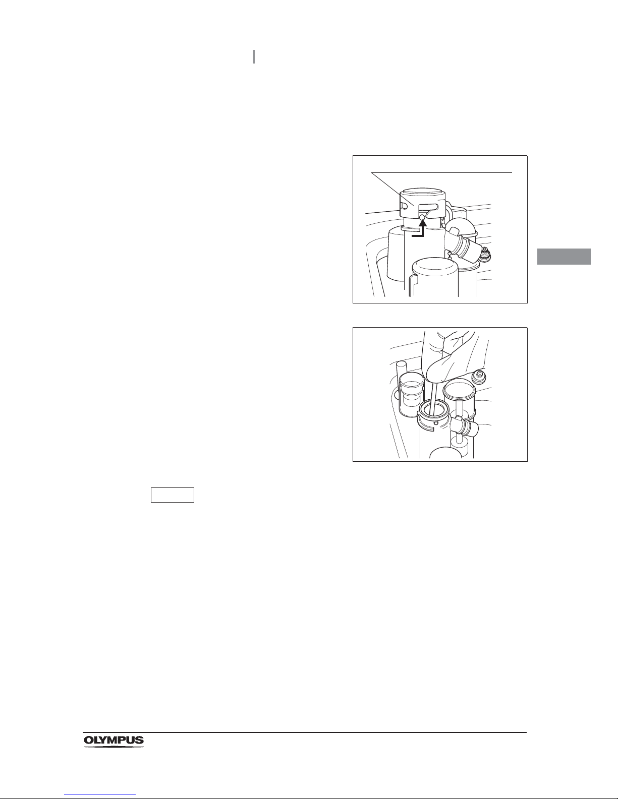
3.7 Checking the MRC level and entering the check result
71
OER-Elite OPERATION MANUAL
Ch.3
Checking the MRC level
1 Press the foot pedal to open the lid.
2 Uncap the disinfectant solution nozzle of the
reprocessing basin by turning the disinfectant
solution nozzle cap in the direction shown right.
Figure 3.45
3 Insert the test strip all the way into the
disinfectant solution nozzle and check the MRC
as described in the test strip instruction
manual. If the concentration is lower than the
effective level, replace the disinfectant solution
by following the instructions in Section 8.2,
“Replacing the disinfectant solution”.
Figure 3.46
NOTE
• Under high temperature and extreme temperature fluctuations, test strip may result
in fail. In such cases, Olympus recommends performing mix LCG and check the
MRC level again.
• Depending on conditions of internal valve, there is a possibility that no disinfectant
solution exist in the disinfectant solution nozzle. In the following cases, perform the
mix LCG, then check the MRC level again.
No reaction is observed on the chemical indicator after checking the MRC level.
Reaction is observed only from the edge parts of the chemical indicator after
checking the MRC level.
If the disinfectant solution in the disinfectant solution nozzle is found insufficient for
checking the MRC level on a regular basis, contact Olympus.
Disinfectant solution nozzle cap
Page 82
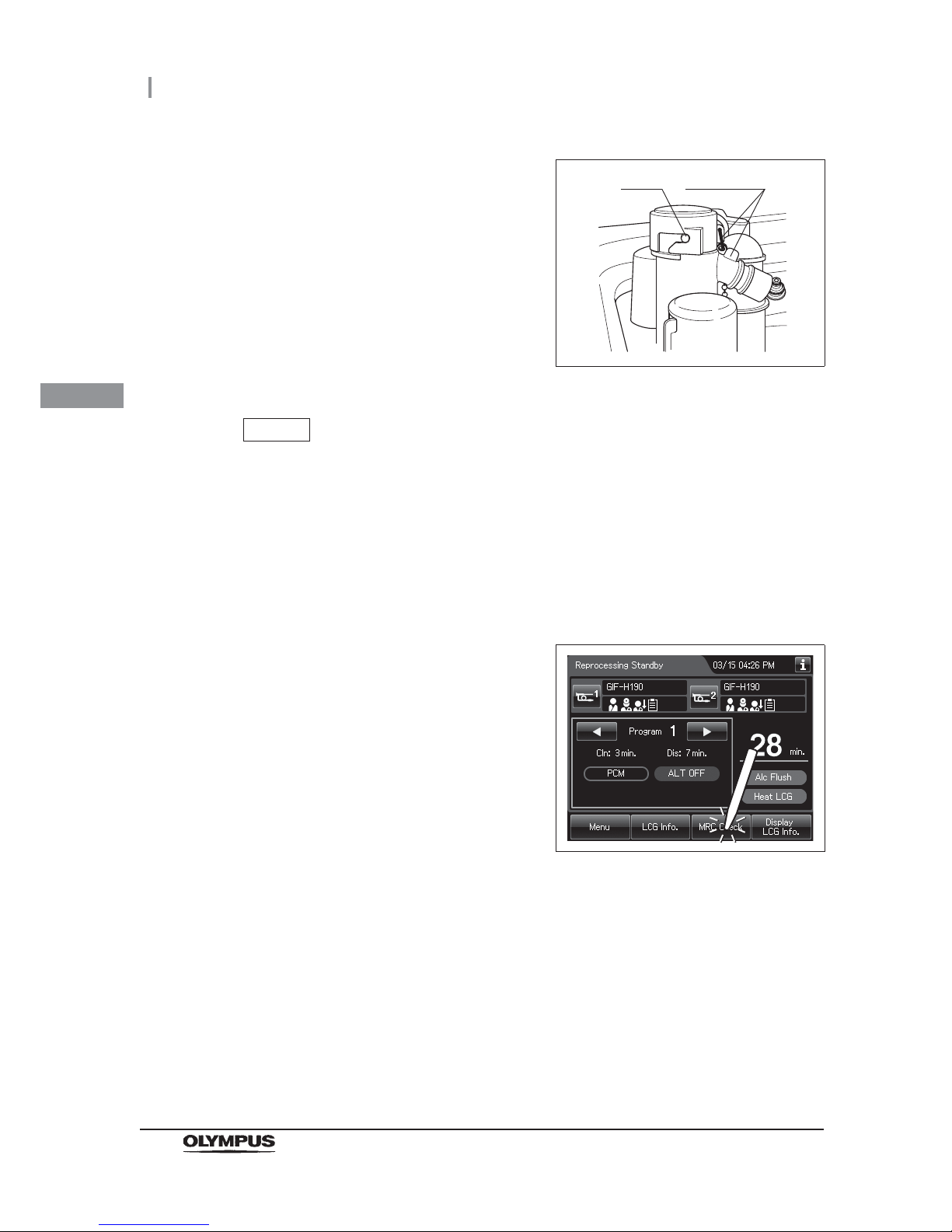
72
3.7 Checking the MRC level and entering the check result
OER-Elite OPERATION MANUAL
Ch.3
NOTE
Be sure to return the disinfectant solution nozzle cap to the original position.
Otherwise, the disinfectant solution inside the nozzle may be diluted in the next
process and next MRC check will be failed even if the concentration of LCG in the
tank is above its MRC. In this case, perform mix LCG, then check MRC again.
Entering the check result
4 Attach the disinfectant solution nozzle cap to
the original position on the disinfectant solution
nozzle. Make sure that the pin returns to the
original position, and the projection of the
disinfectant solution nozzle cap is aligned to the
projection of the disinfectant solution nozzle.
Figure 3.47
1 Display the Reprocessing Standby screen and
Press the “MRC Check” button.
Figure 3.48
Pin
projection
Page 83
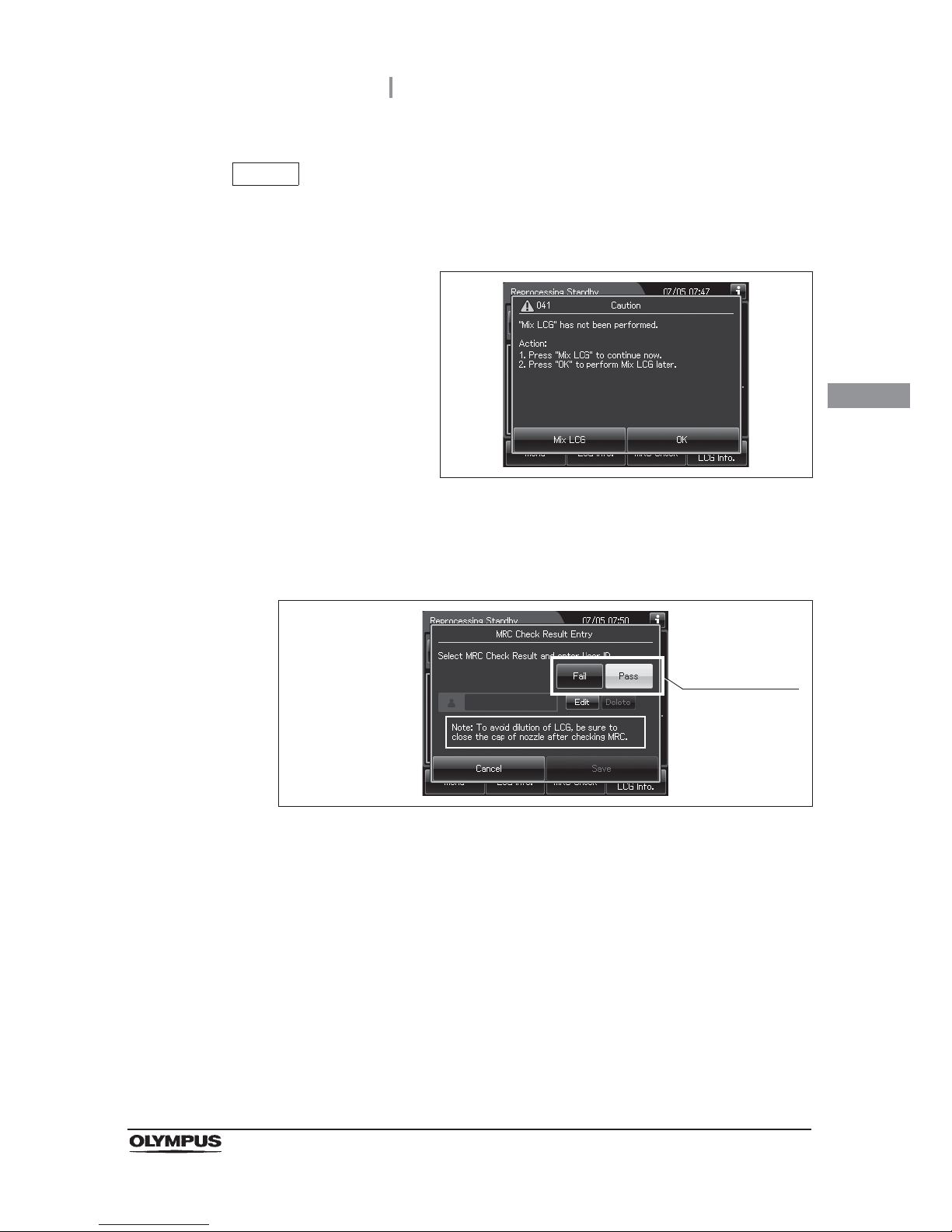
3.7 Checking the MRC level and entering the check result
73
OER-Elite OPERATION MANUAL
Ch.3
NOTE
If the touch screen displays a screen as shown in following figure, perform the LCG
Mixing. If not completed Mix LCG, cannot see the MRC check result. For detailed
on “Mix LCG”, refer to Section 7.4, “Mix LCG”.
Figure 3.49
2 Select the button that corresponds with the result of the MRC check. The button turns
white.
Figure 3.50
Select the result
of the MRC check
using the test
strip.
Page 84
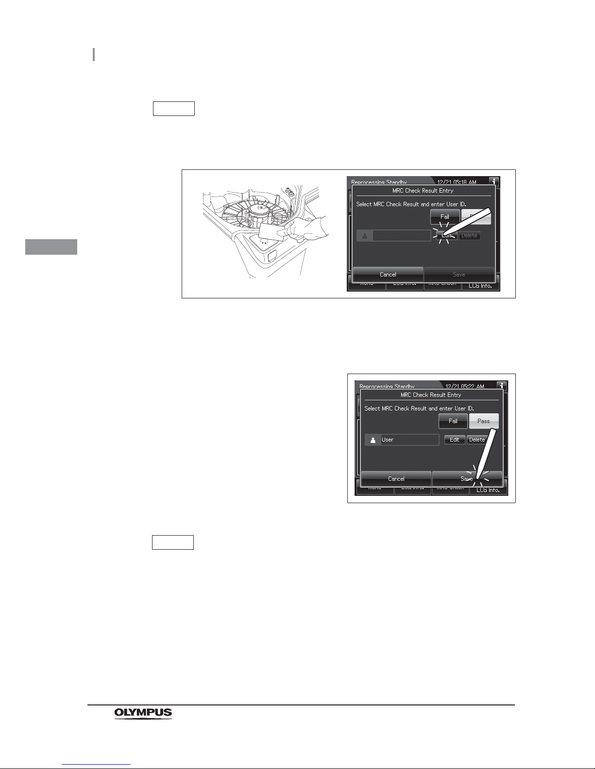
74
3.7 Checking the MRC level and entering the check result
OER-Elite OPERATION MANUAL
Ch.3
NOTE
If the “Save” button is pressed after “Fail” has been selected, the processes that
use the disinfectant solution cannot be started.
NOTE
• Input the user ID by following the instructions in Section 3.6, “Entering ID” (If
applicable). Hold the user ID card in parallel with the ID reader section of the
reprocessor or press the “Edit” button for software keyboard input.
Figure 3.51
• The user ID input can be omitted according to the user ID input setting. For details,
refer to Section 4.5, “User ID Setting”.
3 Press the “Save” button.
Figure 3.52
Page 85

4.1 Setting menu
75
OER-Elite OPERATION MANUAL
Ch.4
Chapter 4 Settings
To change the settings of the reprocessor, press “Settings” on the Menu Screen.
This menu is composed of three pages. To go between the pages, press the next page button or the
previous page button.
4.1 Setting menu
Page 86
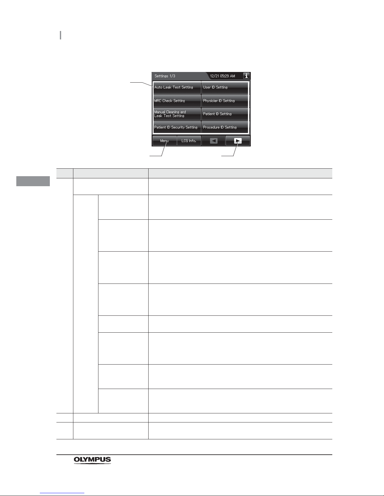
76
4.1 Setting menu
OER-Elite OPERATION MANUAL
Ch.4
No. Button Description
1 Setting item button Press to display the buttons for starting various Functions.
Press the button for the desired function.
Page 1 Auto Leak Test
Setting
This setting sets the timing of auto leak test when it is included in the
reprocessing process.
oRefer to Section 4.2, “Auto leak test setting”.
MRC Check Setting When this setting is activated and the MRC check result is not input before
start of the following process, the reprocessor inhibits the start of the
following process and message screen is displayed.
oRefer to Section 4.3, “MRC check setting”.
Manual Cleaning
and Leak Test
Setting
When this setting is activated, the confirmation results of a manual cleaning
and the leak test before manual cleaning can be selected after the scope ID
input.
oRefer to Section 4.4, “Manual cleaning and leak test setting”.
Patient ID Security
Setting
When the setting is activated, patient data will not be exported or printed from
the OER-Elite. Even this setting is activated, data except the patient data can
be exported to the portable memory or printed.
oRefer to Section 4.8, “Patient ID security setting”.
User ID Setting When this setting is activated, the user ID can be input in each process.
oRefer to Section 4.5, “User ID Setting”.
Physician ID
Setting
When this setting is activated, the physician ID of the endoscope performing
the examination can be input before starting reprocessing process and
leaking scope decontamination and recorded in the reprocessing record.
oRefer to Section 4.6, “Physician ID setting”.
Patient ID Setting When this setting is activated, the ID of the patient receiving the endoscopic
examination can be input and recorded in the reprocessing records.
oRefer to Section 4.7, “Patient ID setting”.
Procedure ID
Setting
When this setting is activated, the procedure ID can be entered before
starting “Reprocessing”.
oRefer to Section 4.9, “Procedure ID setting”.
2 Menu button Press to go to the Menu.
3 Next page button Press to go to the next page. When there is no further page to go forward to,
the button turns gray and becomes unavailable.
1
2 3
Page 87
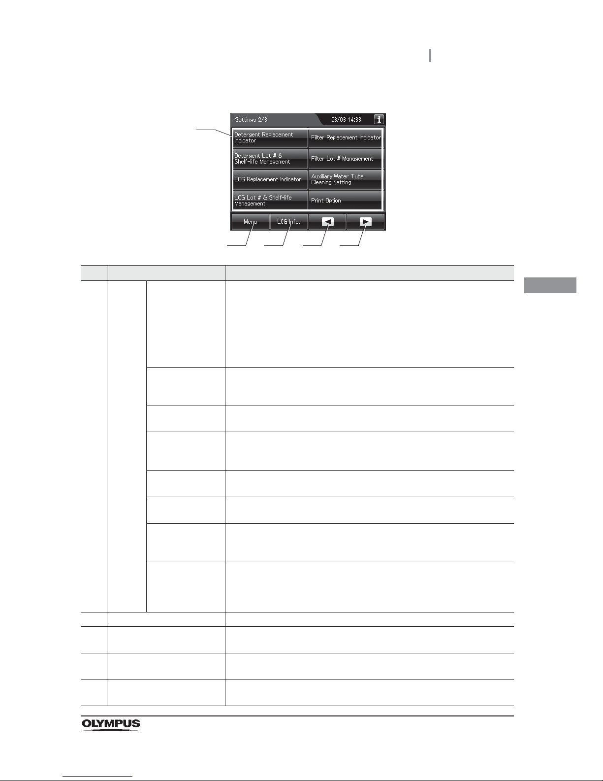
4.1 Setting menu
77
OER-Elite OPERATION MANUAL
Ch.4
No. Button Description
1 Page 2 Detergent
Replacement
Indicator
When this setting is activated, the reprocessor counts the day count (number
of days the detergent is effective after replacement) after each replacement
of detergent and displays the detergent replacement indicator when the day
counts reach to the set value. After reaching to the set value, a pop-up
message screen opens prior to the start of reprocessing and inhibit starting
the process.
oRefer to Section 4.10, “Detergent replacement indicator”.
Detergent Lot # &
Shelf-Life
Management
This setting sets the shelf life and lot number that are input when replacing
the detergent.
oRefer to Section 4.11, “Detergent lot number and shelf-life management”.
LCG Replacement
Indicator
This setting sets the display of the disinfectant solution replacement indicator.
oRefer to Section 4.12, “LCG replacement indicator”.
LCG Lot # &
Shelf-Life
Management
This setting sets the shelf life and lot number that are input when replacing
the disinfectant solution.
oRefer to Section 4.13, “LCG lot number and shelf-life management”.
Filter Replacement
Indicator
This setting sets the display of the Filter Replacement Indicator.
oRefer to Section 4.14, “Filter replacement indicator”.
Filter Lot #
Management
This setting sets the lot number that is input when replacing the filters.
oRefer to Section 4.15, “Filter lot number management”.
Auxiliary Water
Tube Cleaning
Setting
This setting sets the reprocessing of the auxiliary water tube together with
endoscopes.
oRefer to Section 4.16, “Auxiliary water tube cleaning setting”.
Print Option This setting sets the auto printing of the result of reprocessing, auto leak test,
manual leak test or leaking scope decontamination. To activate this setting,
an optional MAJ-2144 printer set is necessary.
oRefer to Section 4.17, “Print option”.
2 Menu button Press to go to the Menu.
3 LCG Info. button Press to open the LCG Info. display.
oRefer to Section 3.5, “LCG Info. screen”.
4 Previous page button Press to return to the previous. When there is no further page to turn back to,
the button turns gray and becomes unavailable.
5 Next page button Press to go to the next page. When there is no further page to go forward to,
the button turns gray and becomes unavailable.
1
2 3 4 5
Page 88
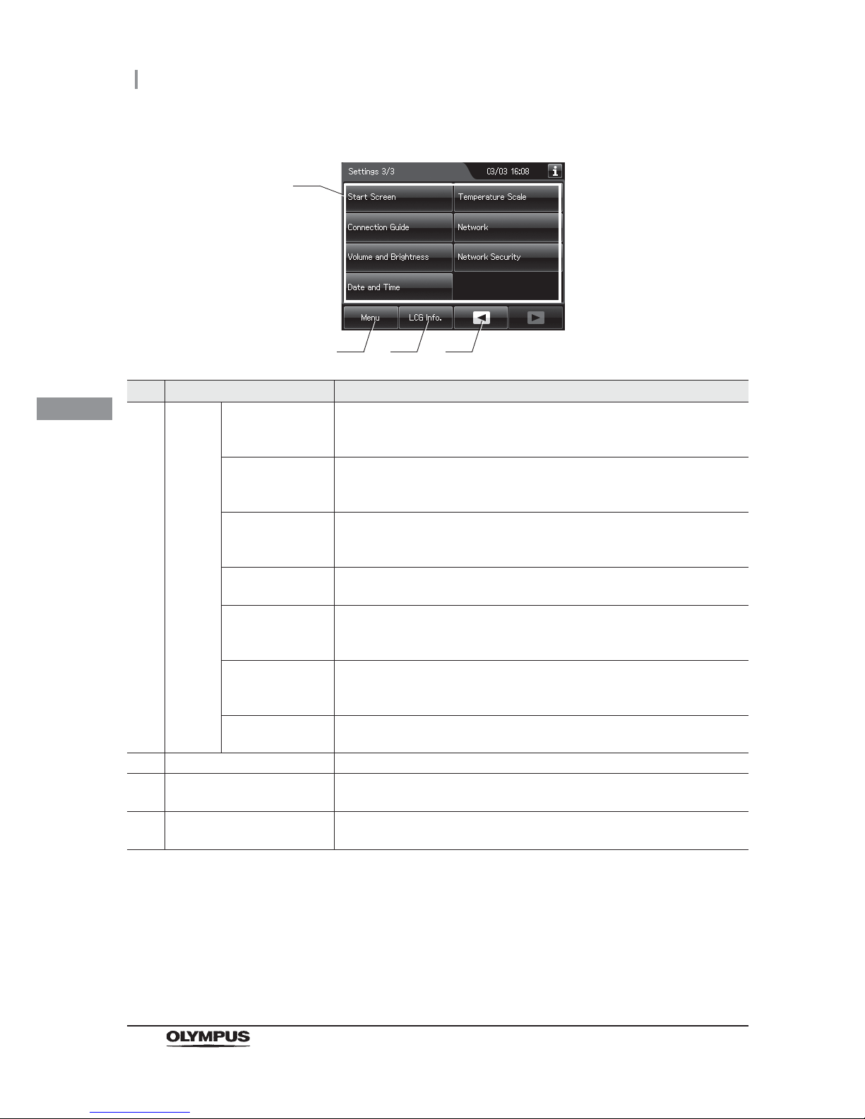
78
4.1 Setting menu
OER-Elite OPERATION MANUAL
Ch.4
No. Button Description
1 Page 3 Start Screen This setting sets the display that appears after the startup display at power
ON.
oRefer to Section 4.18, “Start screen”.
Connection Guide This setting sets the automatic display of the Connection Guide screen after
the Scope ID reading in the reprocessing program.
oRefer to Section 4.19, “Connection guide”.
Volume and
Brightness
This setting sets the volume of buzzer sound, etc., the brightness of the touch
screen and the panel press tone.
oRefer to Section 4.20, “Volume and brightness”.
Date and Time This setting sets the date display format and the clock of the reprocessor.
oRefer to Section 4.21, “Date and time”.
Temperature Scale This setting sets the scale used in the disinfectant solution temperature
display.
oRefer to Section 4.22, “Temperature scale”.
Network This setting sets the information required for connecting the reprocessor to a
Network.
oRefer to Section 4.23, “Network setting”.
Network Security This setting sets the security of the Network-related Settings.
oRefer to Section 4.24, “Network security”.
2 Menu button Press to go to the Menu.
3 LCG Info. button Press to open the LCG Info. display.
oRefer to Section 3.5, “LCG Info. screen”.
4 Previous page button Press to return to the previous. When there is no further page to turn back to,
the button turns gray and becomes unavailable.
1
2 3 4
Page 89

4.2 Auto leak test setting
79
OER-Elite OPERATION MANUAL
Ch.4
This setting is to set the timing of the auto leak test when this function is included in the reprocessing
process.
For the auto leak test in the reprocessing process, refer to “ Auto leak test” on page 221.
CAUTION
Always perform leak test in a sink before manual cleaning. If the endoscope has a
water leaking point, water may penetrate the scope during manual cleaning, in
which case the scope may break down.
4.2 Auto leak test setting
1 Select the “Auto Leak Test Setting” on the settings menu.
Page 90
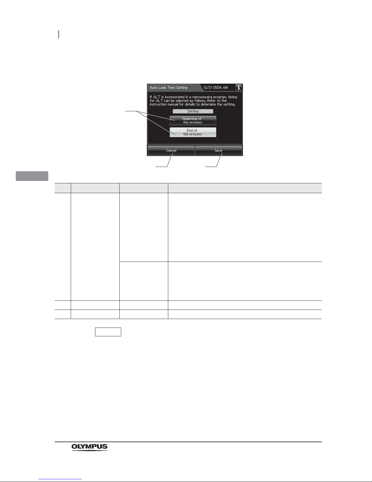
80
4.2 Auto leak test setting
OER-Elite OPERATION MANUAL
Ch.4
NOTE
The selected settings are displayed with white buttons.
2 Select setting from options.
No. Item/Button Setting options Description
1 ALT setting Beginning of the
process
Auto leak test is performed at the starting of “Reprocessing”. The
reprocessing process time is extended by about 2 minutes. If
“Beginning of the process” is selected and hot water is used for
manual cleaning, the ALT result may be “Leaked” even though the
endoscope has no leakage. The leak test result may become
“Leaked” depending on the temperature of the endoscope. To
perform auto leak test with the ultrasonic endoscope, wait for more
than 30 minutes. To perform it with the other type of endoscope,
wait for more than 15 minutes.
End of the process
(default)
Auto leak test is performed at the end of “Reprocessing”. The
reprocessing process time is extended by about 2 – 7 minutes.
When “End of the process” was chosen and there is a leak with an
endoscope, water may enter the endoscope from the leakage
point.
2 Cancel – Returns to the Setting menu without saving the selected setting.
3 Save – Returns to the Setting menu after saving the selected setting.
3 Press the “Save” button to save the selected setting.
1
2 3
Page 91
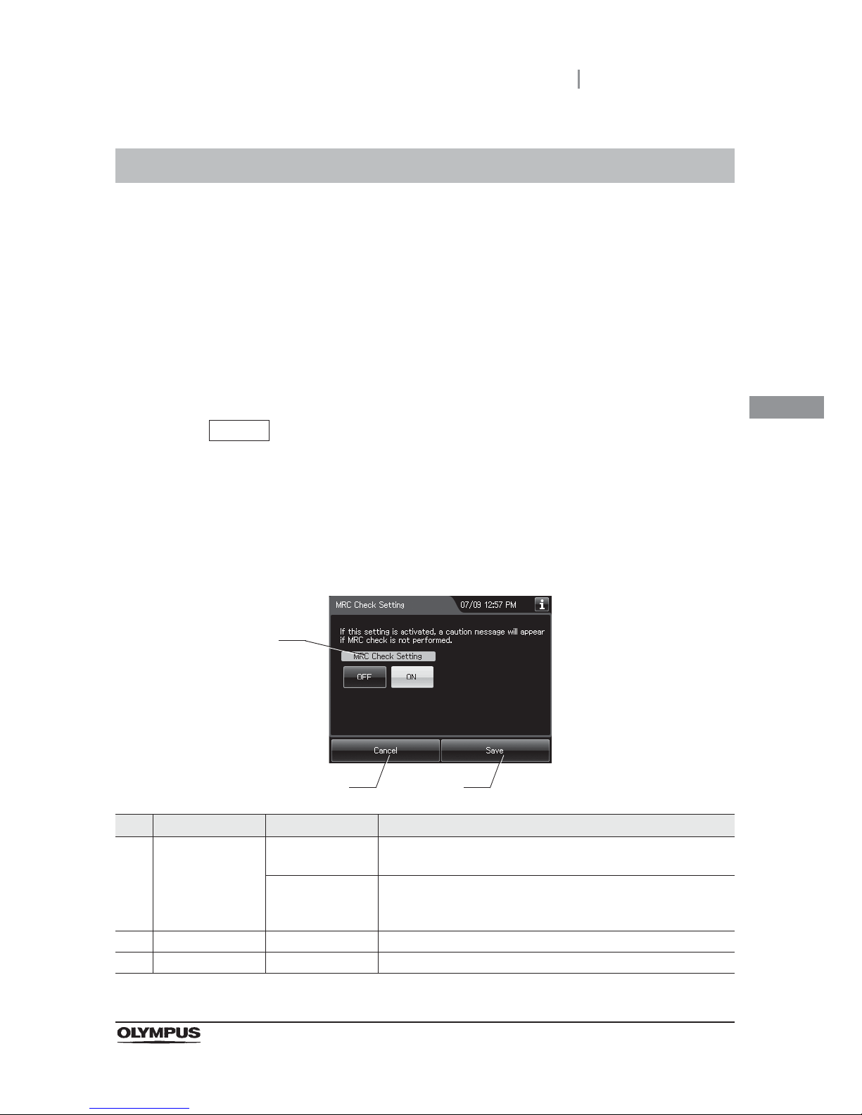
4.3 MRC check setting
81
OER-Elite OPERATION MANUAL
Ch.4
When this setting is activated and the MRC check result is not input before start of the following
process, the reprocessor inhibits the start of the following process and message screen is displayed.
Reprocessing
Leaking Scope Decontamination
Water Line Disinfection
Self-disinfection & Water sampling
Detergent Line Disinfection
Alcohol Line Disinfection
NOTE
This setting is provided to prevent forgetting of the input of the MRC check result.
The MRC check result can be input even when this setting is disabled.
4.3 MRC check setting
1 Select “MRC Check Setting” on the settings menu.
2 Select setting from options.
No. Item/Button Setting options Description
1 MRC Check Setting OFF The reprocessing process starts even if the disinfectant solution
concentration check result is not input.
ON (default) If the disinfectant solution concentration check result is not input
before start of the process, the reprocessor inhibits start of the
process and notifies that the check result is not input.
2 Cancel – Returns to the Setting menu without saving the selected setting.
3 Save – Returns to the Setting menu after saving the selected setting.
1
2 3
Page 92
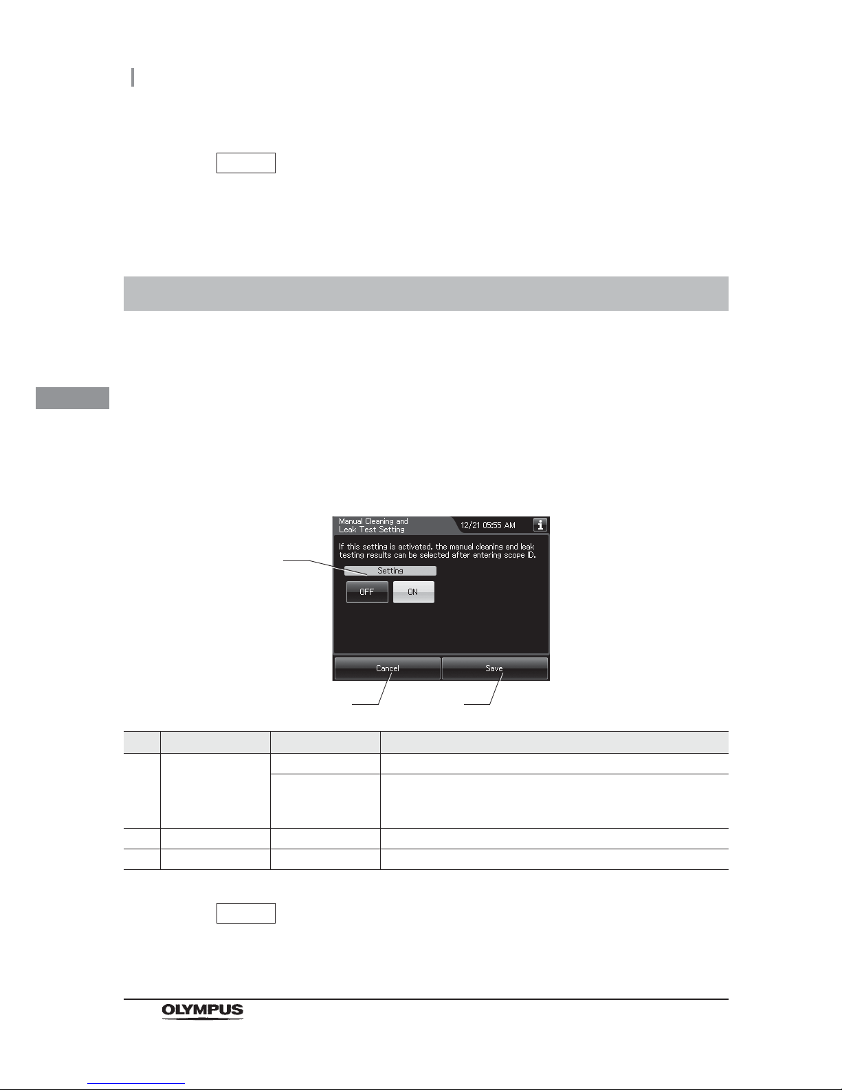
82
4.4 Manual cleaning and leak test setting
OER-Elite OPERATION MANUAL
Ch.4
When this setting is activated, users can confirm if a manual cleaning and leak test have been
performed based on the scope ID. When the setting is On, those inputs are necessary. The manual
cleaning and leak test confirmations are linked to the scope ID's reprocessing records or leaking scope
decontamination records.
NOTE
The selected settings are displayed with white buttons.
3 Press the “Save” button to save the selected setting.
4.4 Manual cleaning and leak test setting
1 Select “Manual Cleaning and leak test Setting” on the settings menu.
2 Select setting from options.
No. Item/Button Setting options Description
1 Manual Cleaning
and leak test
Setting
OFF Disables the data entry for result of manual cleaning and leak test.
ON (default) Before starting “Reprocessing” and “Leaking Scope
Decontamination” are entered for each endoscope's result about
manual cleaning and leak test.
2 Cancel – Returns to the Setting menu without saving the selected setting.
3 Save – Returns to the Setting menu after saving the selected setting.
NOTE
The selected settings are displayed with white buttons.
1
2 3
Page 93
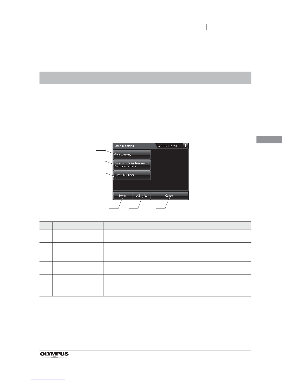
4.5 User ID Setting
83
OER-Elite OPERATION MANUAL
Ch.4
When this setting is activated, the user ID can be inputted in each process and the process cannot be
started without inputting User ID.
3 Press the “Save” button to save the selected setting.
4.5 User ID Setting
1 Select “User ID setting” on the Settings menu.
2 Select the function to change the user ID setting.
No. Button Description
1 Reprocessing Goes to the user ID Setting for “Reprocessing”.
oRefer to “ User ID setting (reprocessing)” on page 84.
2 Functions & Replacement
of Consumable Items
Goes to the user ID Setting for “Functions” and “Replacement of Consumable
Items”.
oRefer to “ User ID setting (functions and replacement)” on page 86.
3 Heat LCG Timer Goes to the user ID Setting for “Heat LCG Timer”.
oRefer to “ User ID setting (Heat LCG Timer)” on page 87.
4 Menu Returns to the Menu screen.
5 LCG Info. Open the disinfectant information screen.
6 Cancel Returns to the Setting menu.
1
2
3
4 5 6
Page 94
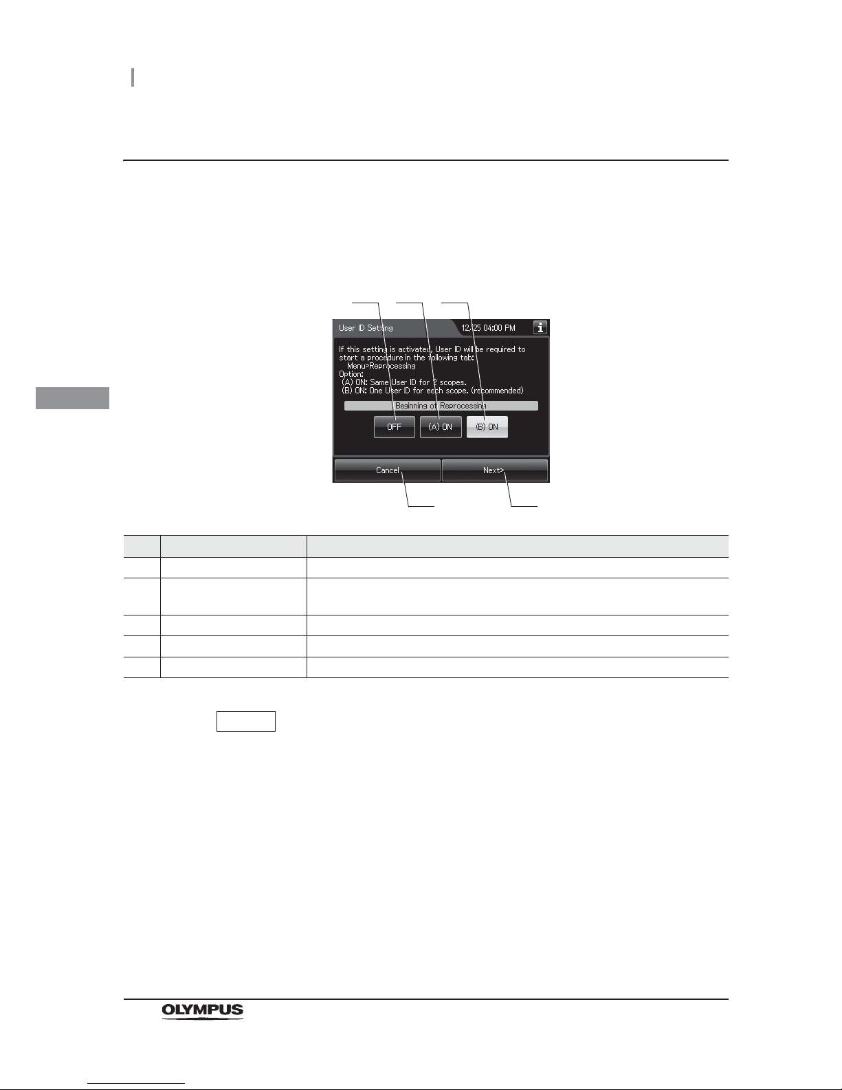
84
4.5 User ID Setting
OER-Elite OPERATION MANUAL
Ch.4
User ID setting (reprocessing)
When this setting is activated, User ID can be entered before and/or after starting reprocessing
process and recorded in the reprocessing record.
1 Select the setting for user ID entry before beginning of reprocessing process.
No. Setting Options Description
1 OFF Disables the user ID entry before starting reprocessing process.
2 (A) ON One User ID can be input for two endoscopes before starting reprocessing
process.
3 (B) ON (default) User ID can be input for each endoscope before starting reprocessing process.
4 Cancel Returns to the previous screen.
5 Next Goes to the next setting.
NOTE
• The selected settings are displayed with white buttons.
• Only one User ID can be input at the end of reprocessing process.
• If the setting is activated, User ID input before beginning reprocessing process
cannot be skipped.
2 Press the “Next” button.
1 2 3
4 5
Page 95
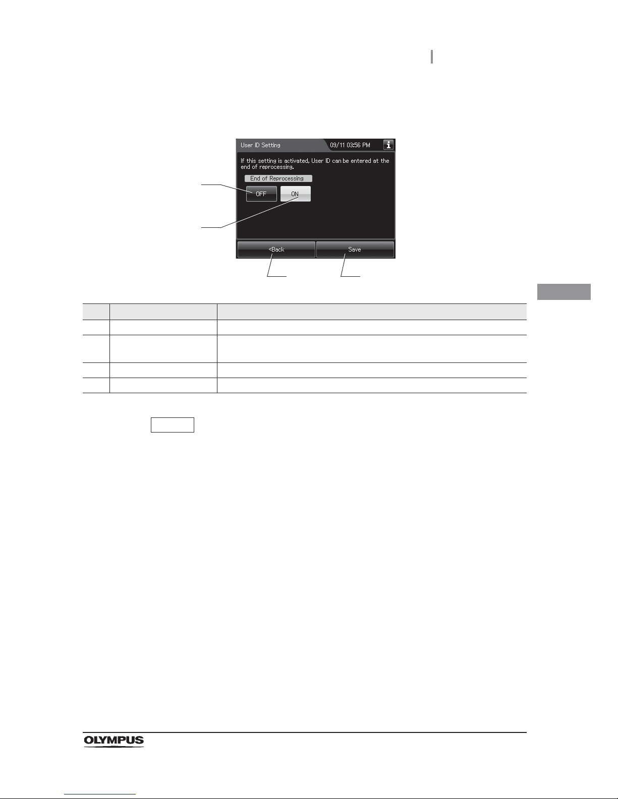
4.5 User ID Setting
85
OER-Elite OPERATION MANUAL
Ch.4
3 Select the setting for User ID entry at the end of reprocessing process.
No. Setting Options Description
1 OFF Disable the user ID entry at the end of reprocessing process.
2 ON (default) User ID can be input at the end of reprocessing process. The lid is locked until
user ID entry is completed.
3 Back Returns to the previous screen.
4 Save Returns to two previous menu after saving the selected setting.
NOTE
• The selected settings are displayed with white buttons.
• If the setting is activated, user ID input at the end of reprocessing process cannot
be skipped.
4 Press the “Save” button to save the selected settings.
3 4
1
2
Page 96
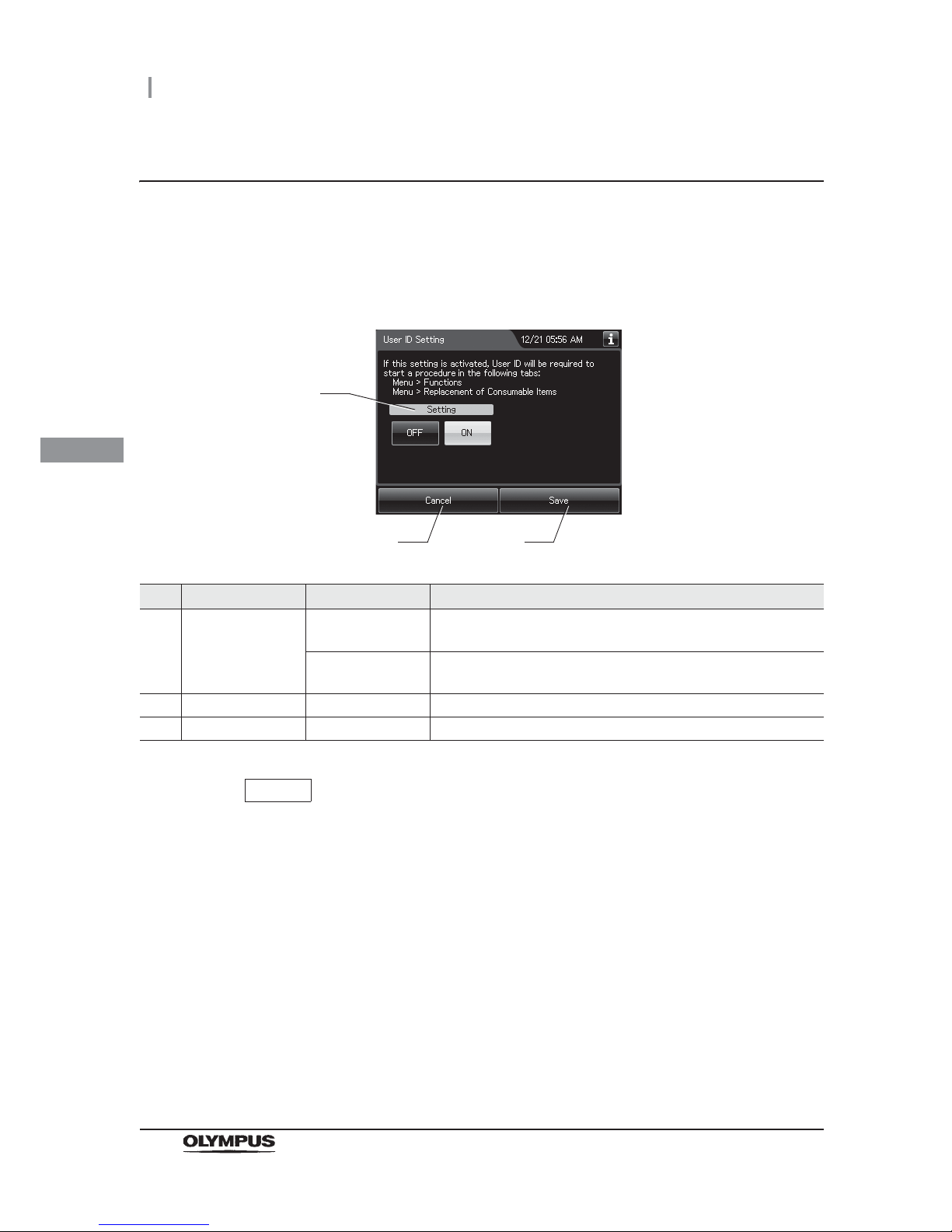
86
4.5 User ID Setting
OER-Elite OPERATION MANUAL
Ch.4
User ID setting (functions and replacement)
When this setting is activated, user ID can be entered before starting each process of “Functions” and
“Replacement of Consumable Items” and recorded in the reprocessing record.
1 Select setting from options.
No. Item/Button Setting options Description
1 User ID Setting
(Functions &
Replacement of
Consumable Items)
OFF Disable the user ID entry for “Functions” and “Replacement of
Consumable Items”.
ON (default) User ID can be input before starting each process of “Functions”
and “Replacement of Consumable Items”.
2 Cancel – Returns to the Setting menu without saving the selected setting.
3 Save – Returns to the Setting menu after saving the selected setting.
NOTE
The selected settings are displayed with white buttons.
2 Press the “Save” button to save the selected setting.
1
2 3
Page 97
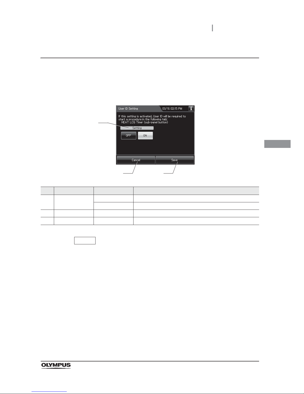
4.5 User ID Setting
87
OER-Elite OPERATION MANUAL
Ch.4
User ID setting (Heat LCG Timer)
When this setting is activated, user ID can be entered before starting “Heat LCG Timer” and recorded
in the reprocessing record.
1 Select setting from options.
No. Item/Button Setting options Description
1 User ID Setting
(Heat LCG Timer)
OFF Disable the user ID entry for “Heat LCG Timer”.
ON (default) Before starting “Heat LCG Timer” are entered the user ID.
2 Cancel – Returns to the Setting menu without saving the selected setting.
3 Save – Returns to the Setting menu after saving the selected setting.
NOTE
The selected settings are displayed with white buttons.
2 Press the “Save” button to save the selected setting.
1
2 3
Page 98
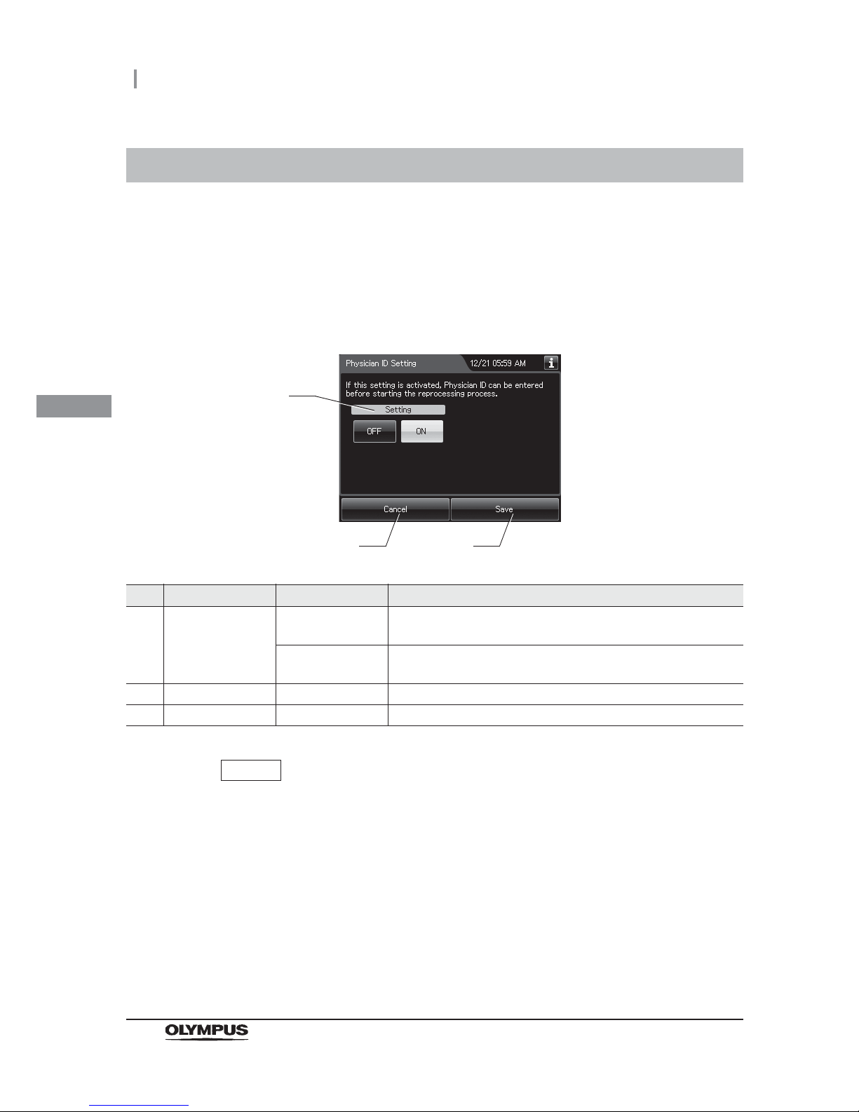
88
4.6 Physician ID setting
OER-Elite OPERATION MANUAL
Ch.4
When this setting is activated, the physician ID of the endoscopist can be input before starting
reprocessing process and leaking scope decontamination and recorded in the reprocessing record.
4.6 Physician ID setting
1 Select “Physician ID Setting” on the settings menu.
2 Select setting from options.
No. Item/Button Setting options Description
1 Physician ID
Setting
OFF Disable the physician ID entry for “Reprocessing” and “Leaking
Scope Decontamination”.
ON (default) User can enter the physician ID before starting “Reprocessing”
and “Leaking Scope Decontamination”.
2 Cancel – Returns to the Setting menu without saving the selected setting.
3 Save – Returns to the Setting menu after saving the selected setting.
NOTE
The selected settings are displayed with white buttons.
3 Press the “Save” button to save the selected setting.
1
2 3
Page 99
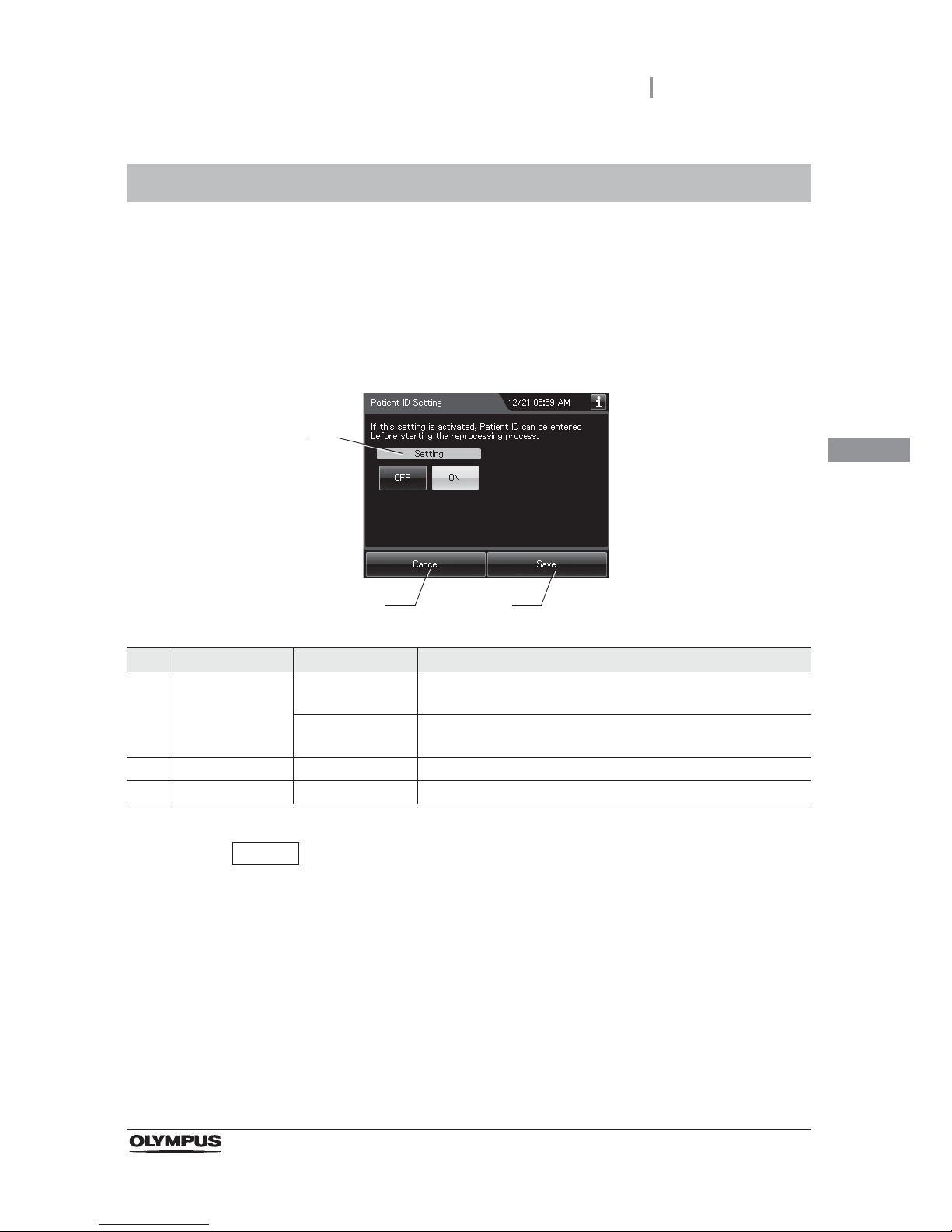
4.7 Patient ID setting
89
OER-Elite OPERATION MANUAL
Ch.4
When this setting is activated, the ID of the patient receiving the endoscopic examination can be input
and recorded in the reprocessing records and recorded in the reprocessing record.
4.7 Patient ID setting
1 Select “Patient ID Setting” on the settings menu.
2 Select setting from options.
No. Item/Button Setting options Description
1 Patient ID Setting OFF Disable the patient ID entry for “Reprocessing” and “Leaking
Scope Decontamination”.
ON (default) User can enter the patient ID before starting “Reprocessing” and
“Leaking Scope Decontamination”.
2 Cancel – Returns to the Setting menu without saving the selected setting.
3 Save – Returns to the Setting menu after saving the selected setting.
NOTE
The selected settings are displayed with white buttons.
3 Press the “Save” button to save the selected setting.
1
2 3
Page 100
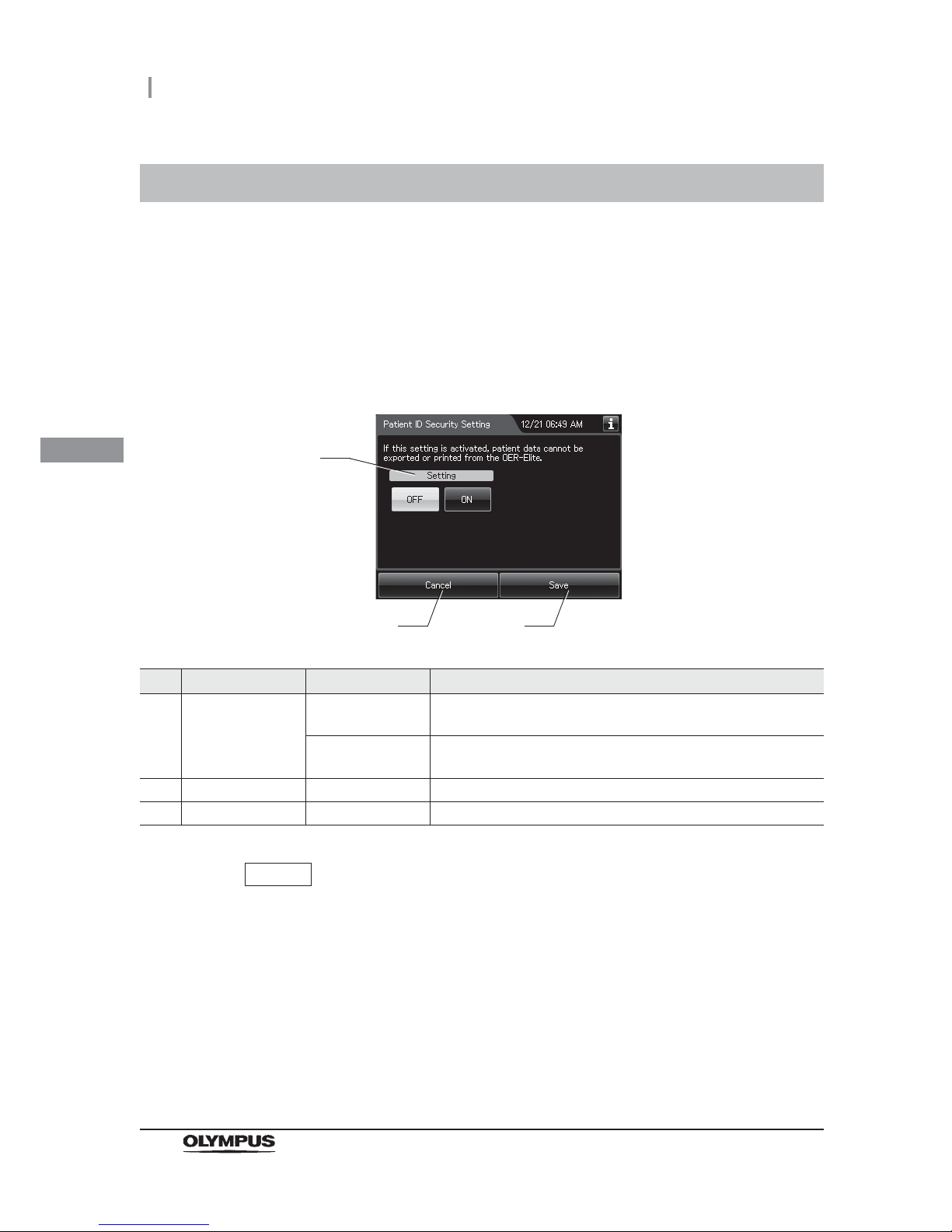
90
4.8 Patient ID security setting
OER-Elite OPERATION MANUAL
Ch.4
When the setting is activated, patient data will not be exported or printed from the OER-Elite. Even this
setting is activated, all data, with exception of patient data can be exported to the portable memory or
printed and recorded in the reprocessing record.
4.8 Patient ID security setting
1 Select “Patient ID Security Setting” on the settings menu.
2 Select setting from options.
No. Item/Button Setting options Description
1 Patient ID Security
Setting
OFF (default) The patient ID is printed on the printer and output to a portable
memory.
ON The printout of the patient ID and its output to a portable memory
are inhibited.
2 Cancel – Returns to the Setting menu without saving the selected setting.
3 Save – Returns to the Setting menu after saving the selected setting.
NOTE
The selected settings are displayed with white buttons.
3 Press the “Save” button to save the selected setting.
1
2 3
 Loading...