

Page 1

µ-40 DIGITAL / Stylus 500/ µ DIGITAL 500
B. DISASSEMBLY AND ASSEMBLY
PROCEDURE
[1] REMOVAL OF FRONT METAL AND REAR COVER ..................................................B-2
[2] REMOVAL OF BARRIER PARTS ............................................................................... B-3
[3] ASSEMBLY OF BARRIER PARTS..............................................................................B-4
[4] GREASE BARRIER PARTS ........................................................................................ B-6
[5] DISASSEMBLY OF REAR COVER UNIT ................................................................... B-7
[6] REMOVAL OF FLPCB................................................................................................. B-8
[7] REMOVE LENS UNIT AND BATTERY CASE UNIT FROM FRONT COVER UNIT ... B-8
[8] SEPARATION OF LENS UNIT AND BATTERY CASE ...............................................B-9
[9] ASSEMBLY OF BATTERY CASE UNIT ...................................................................... B-9
[10] DISASSEMBLY OF LENS CCD UNIT..................................................................... B-10
[11] ASSEMBLY OF BATTERY COVER ......................................................................... B-10
[12] DISASSEMBLY OF ST UNIT ................................................................................... B-11
[13] CAUTIONS FOR ATTACHING LENS UNIT TO FRONT COVER ........................... B-11
B-1 Ver.1
Page 2
B. DISASSEMBLY AND ASSEMBLY PROCEDURE
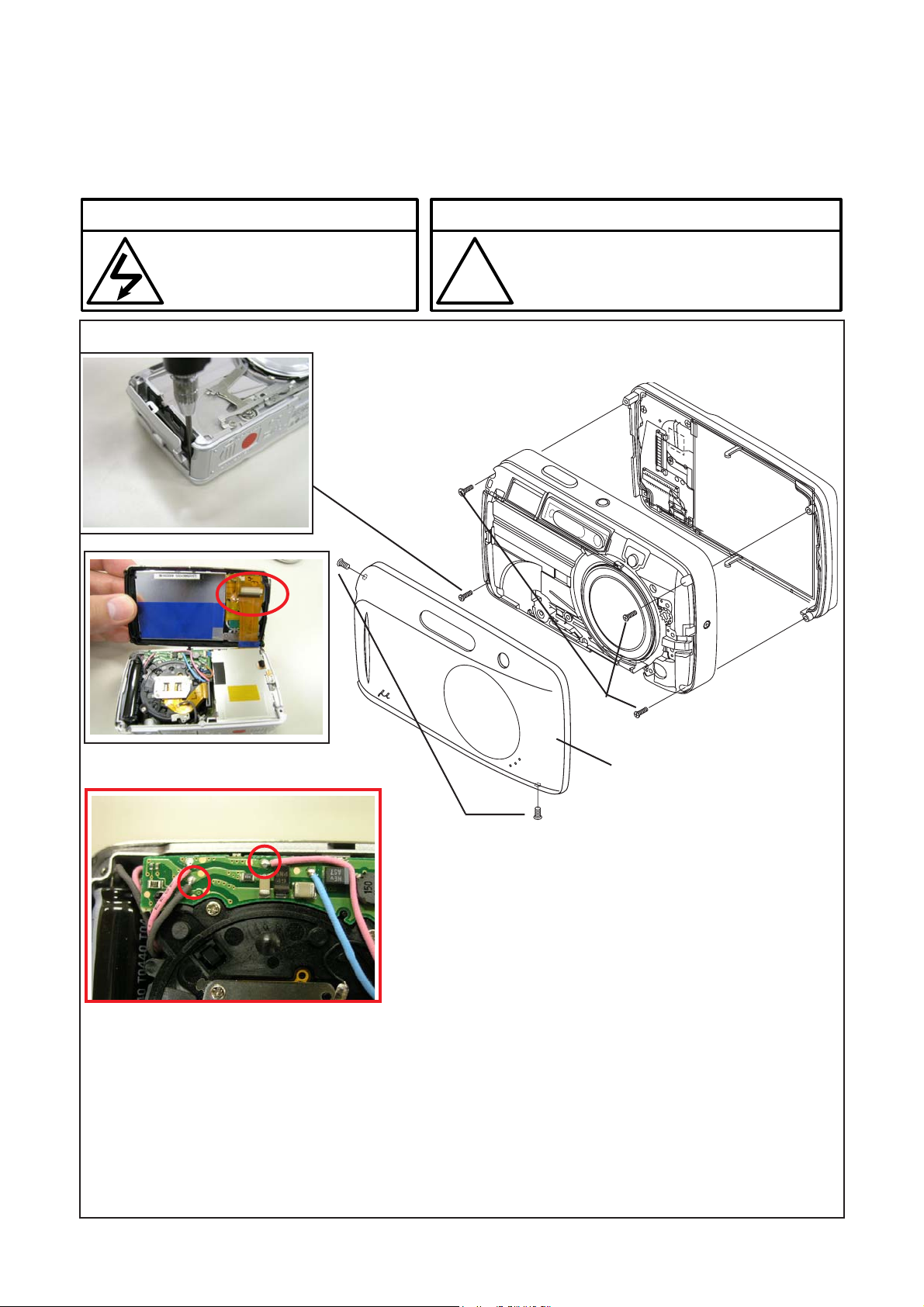
[1] REMOVAL OF FRONT METAL AND REAR COVER
Disassembly perform as follows (1, 2...) and assembly perform by reversing the disassembly steps (...2,1). Be sure to
discharge the main capacitor in procedure 7, then continue to disassembling.
µ-40 DIGITAL / Stylus 500/ µ DIGITAL 500
! Beware of electric shock !
Danger of electric shock.
Use a discharging tool to remove
the electrical charge before working.
4
6
!
Notice
The lead free solder is applied to this product.
Use the lead free solder in working.
5
3
7.Positions of discharge points
1
1. Decoration Screw B(VE778700) x 2
2. Front Metal (Remove dowel of Front Metal as following order: 2 places in upper part, 2 places in side,
1 place in lower side. Do not deform Front Metal.
3. Screw(PUTB1.6-245SN)
4. Screw(PUTB1.6 x 4.5SN) (Remove screw with USB Cover opened half.)
5. Remove Rear Cover.
6. Remove FPC from connecter of SWFPC. (Confirm that FPC is inserted in connector rightly at the time of
assembly without loose connection.)
7. Discharge.
2
B-2 Ver.1
Page 3
µ-40 DIGITAL / Stylus 500/ µ DIGITAL 500
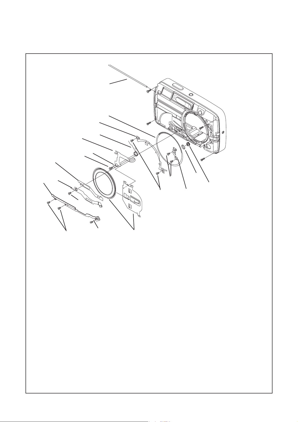
[2] REMOVAL OF BARRIER PARTS
6
17
8
7
5
4
11
B. DISASSEMBLY AND ASSEMBLY PROCEDURE
18
10
3
16
9
1
1. Remove 2 screws(VE773900).
2. Remove screw(CG336800).
3. Remove BR Cap Stopper.
4. Remove screw(PUTB1.6 x 2.8SN).
5. Remove Barrier Lever NW.
6. Remove Barrier Shaft. (After removing SuperX in shaft hole)
7. Remove Barrier Lever and Barrier Unit and Barrier Base together.
8. Remove Barrier Lever Spring.
9. Remove screw(VE945400).
10. Remove Ring Holder2.
11. Remove Barrier Arm Unit.
12. Remove 2 screws(VE773900).
13. Remove BR Gear Holder.
14. Remove BR Idle.
15. Remove BR Idle Shaft.
16. Remove 2 screws(VE773900).
17. Remove Ring Holder1.
18. Remove Ring Gear.
2
7
12
14
15
13
B-3 Ver.1
Page 4
B. DISASSEMBLY AND ASSEMBLY PROCEDURE
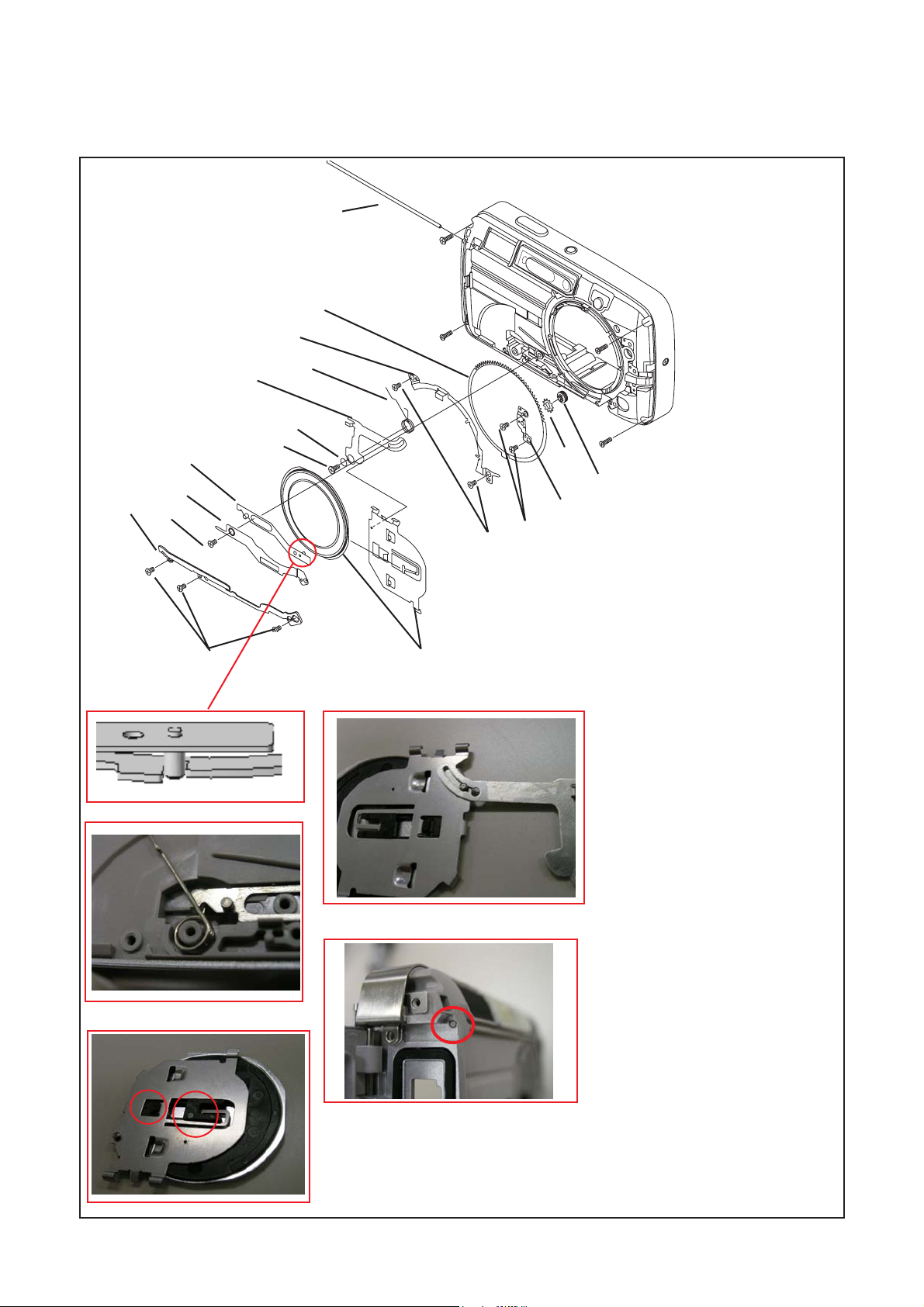
[3] ASSEMBLY OF BARRIER PARTS
2
9
8
11
12
4
µ-40 DIGITAL / Stylus 500/ µ DIGITAL 500
13
1
14
17
4
9
5
6
3
18
8
14
7
15
16
1. Set Ring Gear.
2. Set Ring Holder1.
3. Screw(VE773900) x 2
4. Set Barrier Arm Unit.
5. Set Ring Holder2.
6. Screw(VE945400)
7. Assemble Barrier Unit and
Barrier Base.
8. Assemble 7 and Barrier Lever.
9. Set Barrier Lever Spring.
10. Set 8 on Front Cover Unit.
11. Set Barrier Lever NW.
12. Screw(PUTB1.6 x 2.8SN).
13. Attach Barrier Shaft to Front Cover.
14. Apply SuperX to Barrier Shaft hole.
7
B-4 Ver.1
Page 5
µ-40 DIGITAL / Stylus 500/ µ DIGITAL 500
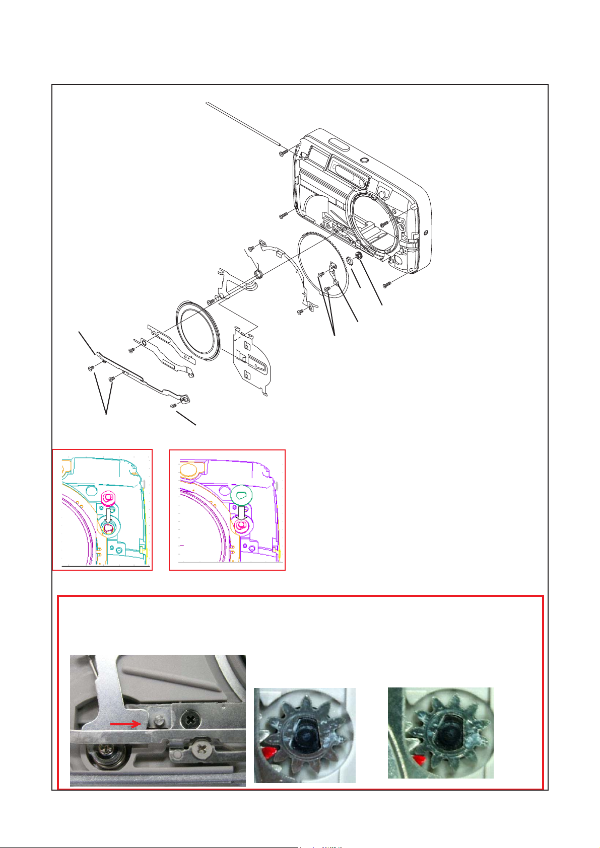
[3] ASSEMBLY OF BARRIER PARTS
B. DISASSEMBLY AND ASSEMBLY PROCEDURE
16
15
16
19
2
20
15
17
18
21
16
15. Set BR Idle Shaft
16. Set BR Idle as instruction bellow.
17. Set BR Gear Holder.
18. Screw(VE773900) x 2
19. Set BR Cap Stopper.
20. Screw(VE773900) x 2
21. Screw(CG336800)
1. Confirm Lens Unit is set down position.
2. Hold pin on the Barrier Arm at the middle of Barrier Lever and Ring Holder2.
3. Set BR Idle to BR Idle Shaft with Ring Gear at the position as picture A bellow.
A(OK)
NG
B-5 Ver.1
Page 6
B. DISASSEMBLY AND ASSEMBLY PROCEDURE
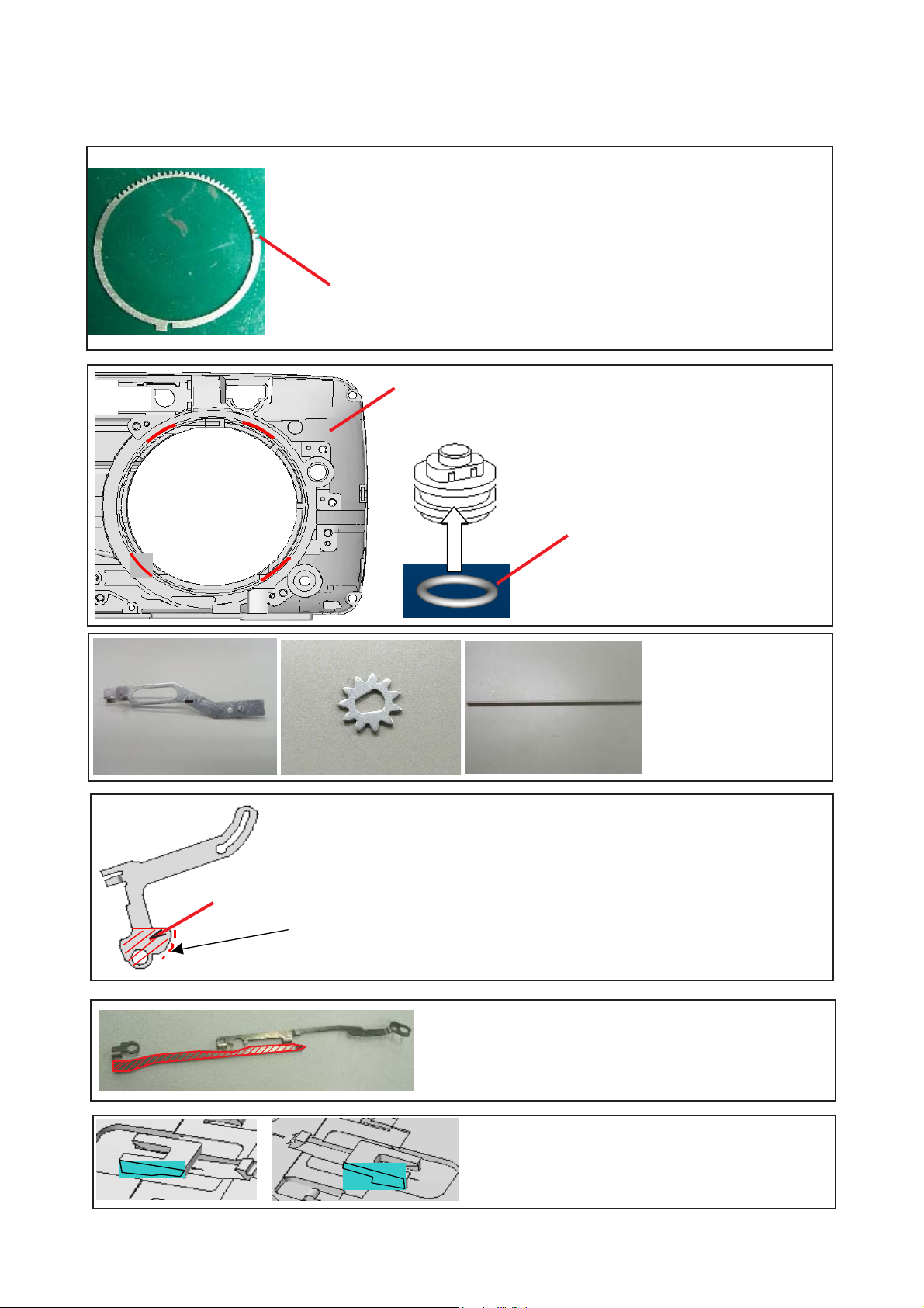
[4] GREASE BARRIER PARTS
µ-40 DIGITAL / Stylus 500/ µ DIGITAL 500
1. Barrier Ring
A. Apply Drysurf KD-1 (OT3306) to all over Barrier Ring.
B. After performing procedure A, apply Hi-Lube FG-30 (OT3304) to inner
surface of Barrier Ring.
When the Barrier Ring has no mark, put a mark to
the second teeth from the edge.
2. Apply Hi-Lube FG-30 (OT3304) to contact face of Front Cover and
Ring Gear (Red part in left figure).
3. Apply Hi-Lube FG-30 (OT3304) to all around
BR Ring.
3. Apply position (all around)
4. Apply Drysurf KD-1
(OT3306) to all over
Barrier Arm, Idle Gear 3,
Barrier Shaft.
6.
A. Apply Drysurf KD-1 (OT3306) to all over Barrier Lever.
B. After performing procedure A, apply Hi-Lube FG-30 (OT3304) to all over the
end face of Barrier Arm.(Black arrow part)
Do not apply FG-30 to upper surface. (Red arrow part).
B
7. Apply Drysurf KD-1 (OT3306) to Barrier Cap Stopper (red part).
8. Apply Drysurf KD-1 (OT3306) to Barrier Base (blue
part).
B-6 Ver.1
Page 7
µ-40 DIGITAL / Stylus 500/ µ DIGITAL 500
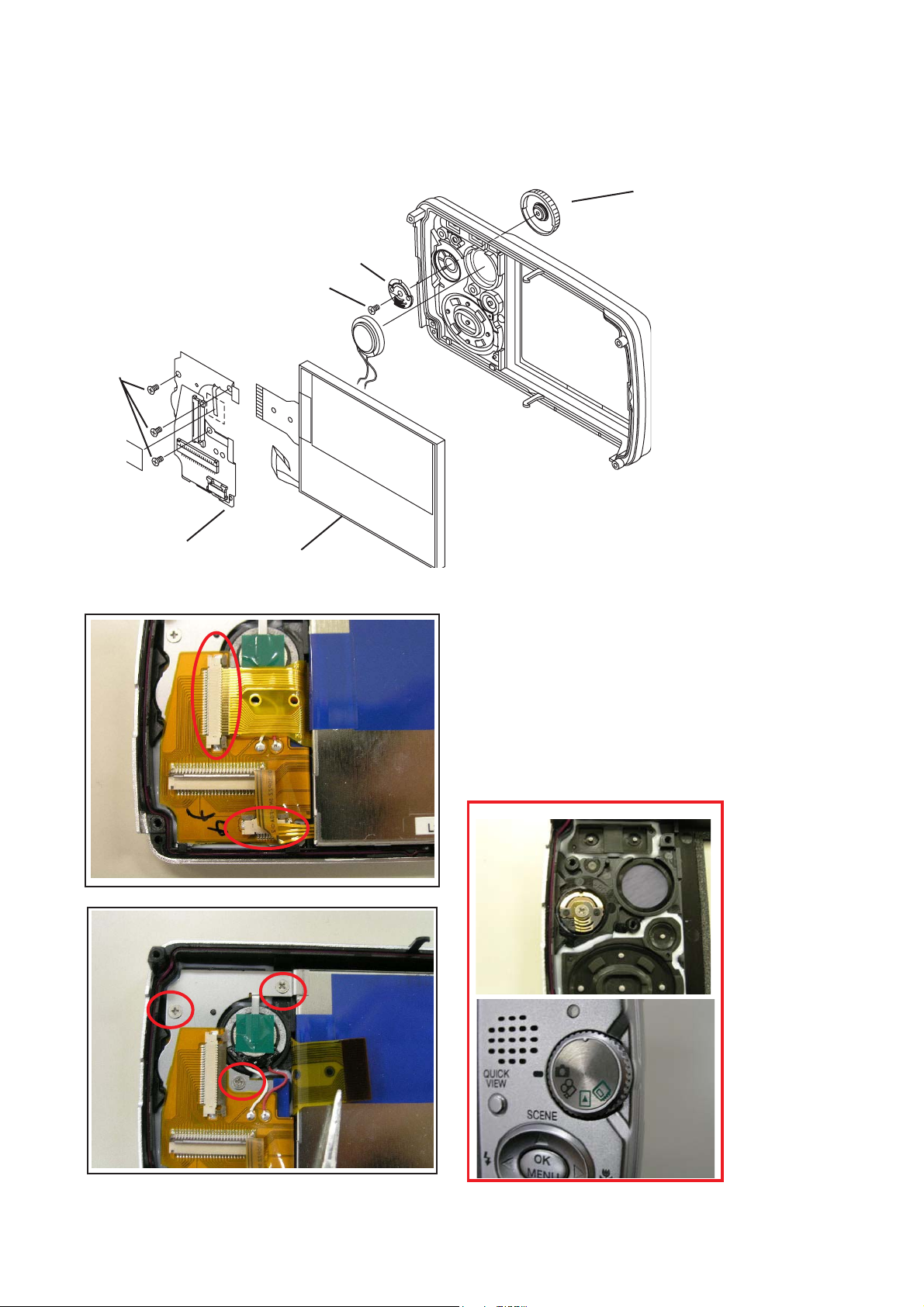
[5] DISASSEMBLY OF REAR COVER UNIT
5
2
3
4
B. DISASSEMBLY AND ASSEMBLY PROCEDURE
7
6
1
2
1. Remove connecter (x2).
2. Screw(VE773900) x 3
3. Remove SWFPC.
4. Remove TFT.
5. Screw(VE773900)
6. Remove MD Base.
7. Remove M Dial.
* Positioning at the time of assembly of M Dial and MD Base
B-7 Ver.1
Page 8

B. DISASSEMBLY AND ASSEMBLY PROCEDURE
µ-40 DIGITAL / Stylus 500/ µ DIGITAL 500
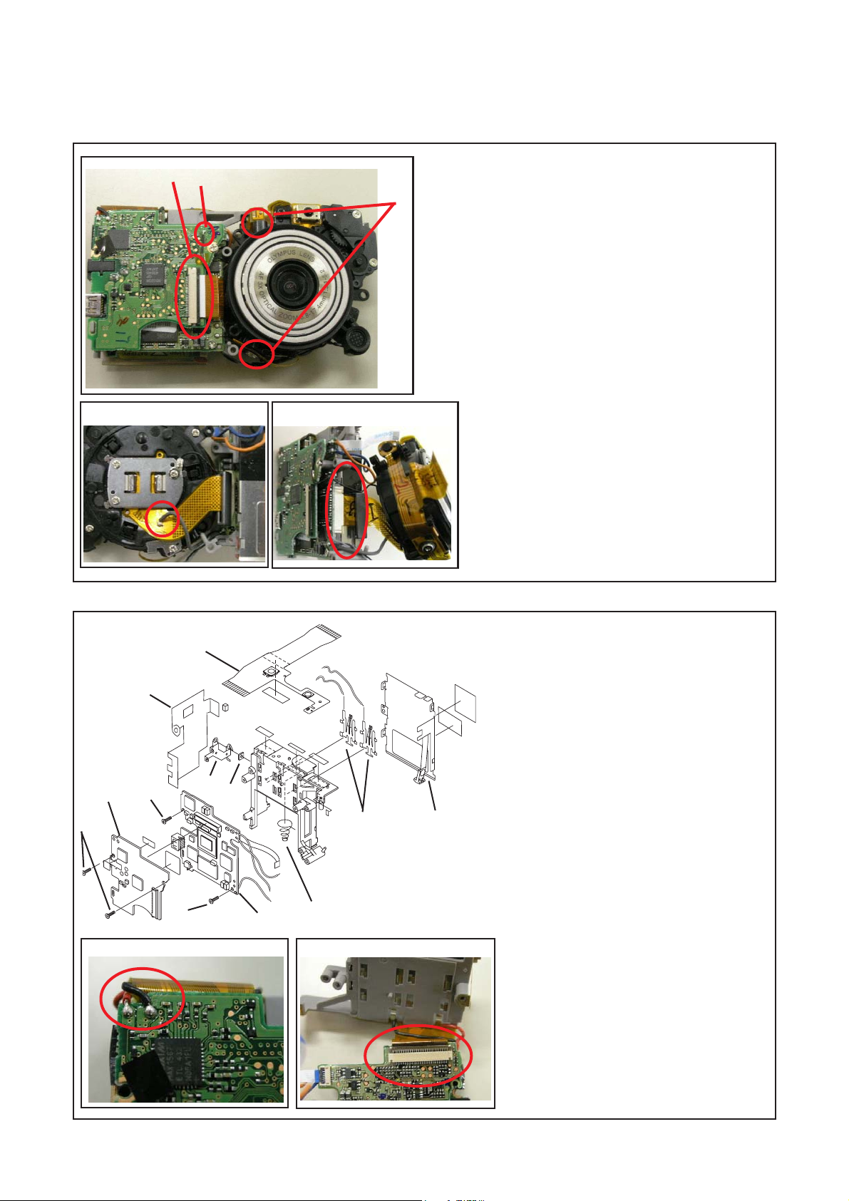
[6] REMOVAL OF FLPCB
1. Unsolder 5 wires. (Red circles in left figure)
2. Screw(PUTB1.6 x 3.5SB) x 2 (Green circles)
3. Remove FPC from connecter. (Yellow circle)
4. FLPCB is removed with main capacitor.
[7] REMOVE LENS UNIT AND BATTERY CASE UNIT FROM FRONT COVER UNIT
5
4
6
2
7
1
4
3
5
3
1. MK screw(VE945300) x 3
(Red circles in below figure)
2. MK Holder x 6pcs.
3. Screw(PUTB1.6 x 14SN) (Green circle)
1
4. Screw(PUTB1.6 x 8SN) (Yellow circle)
5. Screw(PUTB1.6 x 4SN) (Blue circle)
6. Screw(PUK1.6 x 3.5SN)
7. Pull Lens Unit and Battery Case Unit out
together.
6
B-8 Ver.1
Page 9
µ-40 DIGITAL / Stylus 500/ µ DIGITAL 500
B. DISASSEMBLY AND ASSEMBLY PROCEDURE
[8] SEPARATION OF LENS UNIT AND BATTERY CASE
1
2
3
1. Remove Lens FPC from connector.
2. Unsolder 1 wire.
3. Remove dowel of Battery Case from Lens Unit.
4. Unsolder 1 wire on CCD FPC.
5. Remove CCD FPC from connector.
4
5
[9] ASSEMBLY OF BATTERY CASE UNIT
9
6
5
3
2
10
11
4
7
14
13
12
1. Unsolder 2 wires.
2. Screw(PUTB1.6 x 245SN) x 2
3. Remove PWPCB.
4. Screw(PUTB1.6 x 245SN)
5. Screw(3PUTB1.6 x 3.5SN)
6. Remove EMI2 Sheet.
7. Turn MCPCB.
8. Remove TOP-PFCA from connector on
MCPCB.
9. Remove TOP-PFCA.
10. Remove Side Plate.
11. Remove Nut.
12. Remove Battery Case Cover (4 hooks).
13. Remove Battery Contact (x2).
14. Remove Battery Spring.
1
8
B-9 Ver.1
Page 10

B. DISASSEMBLY AND ASSEMBLY PROCEDURE
[10] DISASSEMBLY OF LENS CCD UNIT
1. Screw(PUTB1.6 x 3.5SN) x 3
2. Remove CCD Spacer(x3) and FC Spacer(x3).
3. Remove CCD Unit.
4. Remove CCD Rubber.
5. Cover Glass
6. LPF Sheet
7. LPF Holder
8. CCD Spacer
µ-40 DIGITAL / Stylus 500/ µ DIGITAL 500
[11] DISASSEMBLY OF BATTERY COVER
1
3
4
5
2
5
1. Pull Battery Cover Shaft out.
2. Pull Battery Cover Spring and Battery Cover Unit are
removed.
3. Screw (PUK1.6 x 222SB) x 2
4. Battery Inner Cover is removed.
5. Slide Battery Plate and remove it from Battery Cover.
*After attaching Battery Cover Shaft, apply Super-X at both side of it.
(Be sure to perform this procedure because the waterproof is lost.)
B-10 Ver.1
Page 11

µ-40 DIGITAL / Stylus 500/ µ DIGITAL 500
[12] DISASSEMBLY OF ST UNIT
B. DISASSEMBLY AND ASSEMBLY PROCEDURE
1
2
[13]CAUTIONS FOR ATTACHING LENS UNIT TO FRONT COVER
1. Remove ST Case ( 3 hooks )
2. Remove ST Unit
1. Set 6 MK Holders (B) to 3 MK Screws
A
B
1
A
B
VE945300 (A).
2. When MK Holder hits Lens Unit while tight-
ening a screw, tighten it for another
four-rotation.
* Because MK Holder may be deformed by
attachment, change it with new one every
disassembly.
B-11 Ver.1
 Loading...