

Page 1

µ-40 DIGITAL / Stylus 500 / µ DIGITAL 500
C. ADJUSTMENT METHOD
[1] TABLE FOR SERVICING TOOLS ...................................................................... C-2
[2] EQUIPMENT ....................................................................................................... C-2
[3] SETUP.................................................................................................................C-2
[4] ADJUSTMENT ITEMS AND ORDER..................................................................C-3
[5] CONNECTING THE CAMERA TO THE COMPUTER
/ DRIVER INSTALLATION ........................................................................... C-3
[6] ADJUSTMENT SPECIFICATIONS .................................................................... C-4
1.Launch the adjustment software ................................................................ C-4
2.How to unplug USB cable ........................................................................... C-4
3.Adjustment method .....................................................................................C-5
1)ZOOM adjustment ....................................................................................C-5
2)Mechanical shutter adjustment ..............................................................C-5
3)CCD defect adjustment ........................................................................... C-5
4)COLOR adjustment ................................................................................. C-6
5)FOCUS adjustment .................................................................................C-6
6)TFT-COM adjustment ..............................................................................C-7
7)DESTINATION area select .......................................................................C-8
8)OPTION .................................................................................................... C-9
C-1 Ver.1
Page 2
C. ADJUSTMENT METHOD
µ-40 DIGITAL / Stylus 500 / µ DIGITAL 500
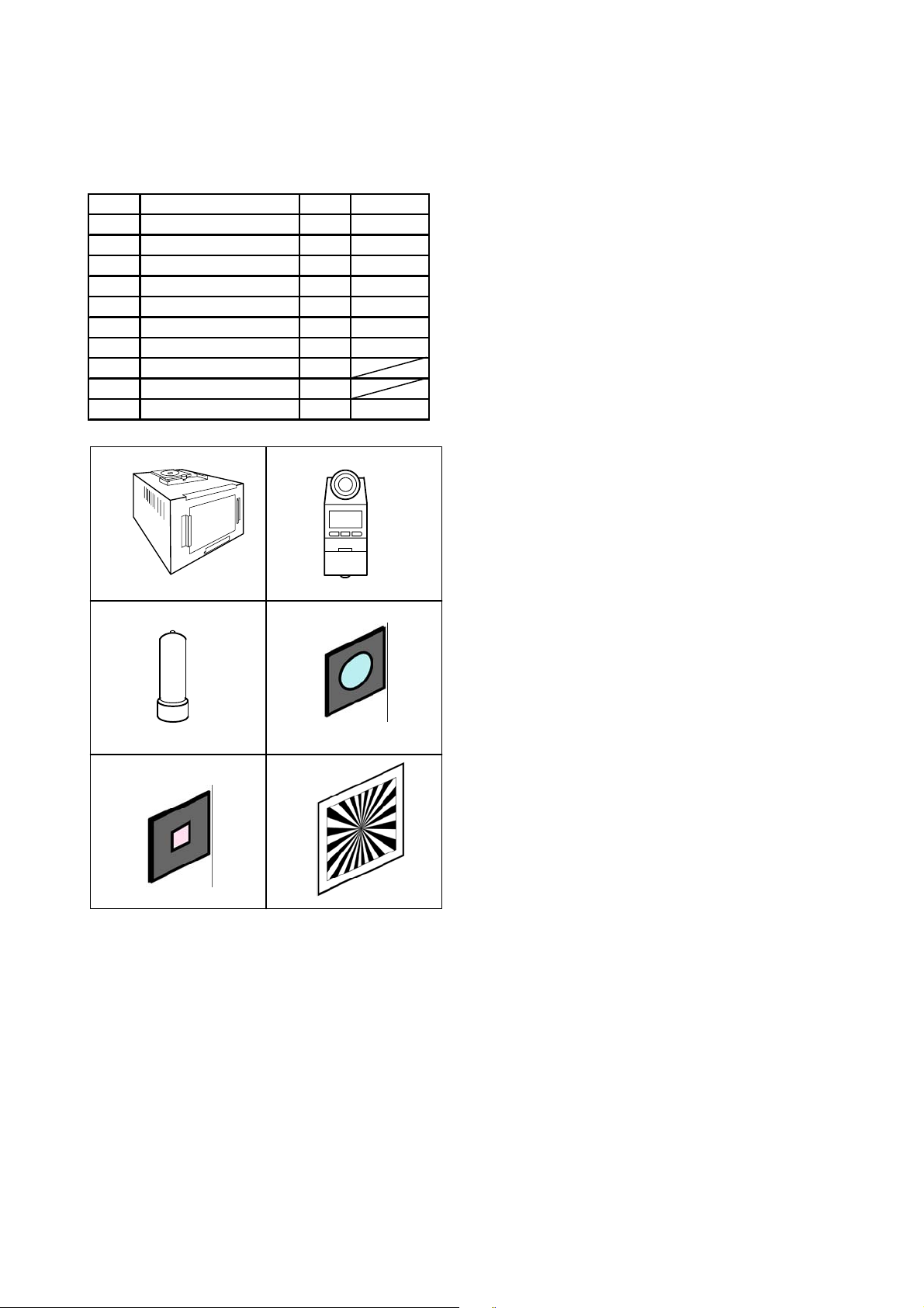
[1] TABLE FOR SEVICING TOOLS
Ref.No. Name NumberPart code
J-1 Halogen Viewer 1 KC0336
J-2 Chroma Meter 1 KC0337
J-3 Spare Lamp 1 KC0339
J-4 IR cut filter (with holder) 1 KC0428
J-5 MC filter (with holder) 1 KC0429
Spare IR cut filter 1 KC0426
Spare MC filter 1 KC0427
J-6 Siemens star chart 1
Adjustment software 1
Black curtain 1 KC0321
J-1 J-2
J-3
J-4
[2] EQUIPMENT
- IBM ® -compatible PC
- USB Cable
- AC adaptor (D-7AC)
- Thermometer
- Fluorescent light
[3] SETUP
1. System requirements
- Windows 98SE/2000
- IBM
® -compatible PC with Pentium processor
- USB port
- 8 MB RAM
- Hard disk drive with at least 15 MB available
- VGA or SVGA monitor with at least 256-color display
2. Installing adjustment software
(1) Install the setup file adjustment in an optical folder
from ISE-Net.
(2) Open " Explorer " and double-click
" OL_Calib221_Ver*.*_SETUP.EXE " file.
(3) Start Install Wizard.
(4) After installation," C:\Di\OL_Calib221 " directory
will be created.
J-5 J-6
C-2 Ver.1
Page 3

µ-40 DIGITAL / Stylus 500 / µ DIGITAL 500
C. ADJUSTMENT METHOD
[4] ADJUSTMENT ITEMS AND ORDER
Adjustment items
1)ZOOM adjustment-------------------- [1.ZOOM]
2)Mechanical shutter adjustment---[2.Mech a Shutter]
3)CCD defect adjustment-------------[3.CCD Defect]
4)Color adjustment--------------------- [4.Color Matrix]
5)Focus adjustm ent-------------------- [5.Focus ]
6)TFT-COM adjustment----------------[6.T-COM]
7)Destination area select------------- [7.Des tination]
8)Writing of the camera Body number
Lens Unit CCD-ASSY LPF TFT MC-PCA
OOO O
OOO O
OOO O
OOO O
OOO O
Changed parts
OO
O
O
[5] CONNECTING THE CAMERA TO THE COMPUTER / DRIVER INSTALLATION
(1) Set the AC adaptor in the camera.
(2) Insert a USB cable in the camera and PC. (Fig.3-1)
(3) Choose "PC" from LCD monitor and push [OK] button. (Fig.3-2)
Note) A personal computer sometimes stops when the camera is plugged in and out with a USB cable.
(4) If recognized as new hardware, install a driver.
Location to save the driver: "C:\Di\OL_Calib221\USB Port Driver"
Fig.3-1
Fig.3-2
C-3Ver.1
Page 4

C. ADJUSTMENT METHOD
µ-40 DIGITAL / Stylus 500 / µ DIGITAL 500
[6] ADJUSTMENT SPECIFICATIONS
1. Launch the adjustment software
(1) Double-click "C:\Di\OL_Calib221\OL_Calib221_Ver*.*.exe"
(2) At the initial launch, two windows open first.
(the window behind doesn't show on Windows 98SE)
(3) Select the language used on PC and the number of "USB Mass storage device"
shown on the window. Click [OK]. (Fig.4-1)
(select only the language on Windows 98SE)
(4) Confirmation message appears and click [Yes]. (Fig.4-2)
(5) Adjustment program starts up and a menu screen appears. (Fig.4-3)
Fig.4-1 Fig.4-2
2. How to unplug USB cable (Windows 2000 only)
Operation procedure:
(1) Click [USB Unplug]. (Fig.4-3)
(2) Confirm "OK" indication. (Fig.4-4)
(3) Unplug USB cable.
Fig.4-3
Fig.4-4
C-4 Ver.1
Page 5

µ-40 DIGITAL / Stylus 500 / µ DIGITAL 500
C. ADJUSTMENT METHOD
3. Adjustment method
1) ZOOM adjustment
Preparation:
-Camera is in communication with PC
Procedure:
(1) Click [1.ZOOM] (Fig.5-1)
(2) Adjustment starts.
(3) Confirm "OK" indication appears. (Fig.5-2)
(4) Adjustment completes.
2) Mechanical shutter adjustment
Preparation:
-Camera is in communication with PC
-Halogen viewer spec brightness : 900+/-100(lux)
color temperature : 3100+/-100(K)
Procedure:
(1) Click [2.Mecha Shutter] (Fig.5-1)
(2) Input the body number of the camera and click [Write]
when MC-PCA was changed. (Fig.5-3)
(3) Align lens end face and Halogen viewer at a distance
of 0cm to 5cm. (Fig.5-4)
(4) Match the lens to the center of the viewer.
(5) Cover a camera with black curtain.
(6) Click [Start]. (Fig.5-5)
(7) Adjustment starts.
(8) Confirm "OK" indication appears. (Fig.5-2)
(9) Adjustment completes.
Camera
Fig.5-1
Fig.5-2
Fig.5-3
0 - 5cm
Halogen Viewer
Fig.5-4
3) CCD defect adjustment
Preparation:
-Camera is in communication with PC
-Halogen viewer spec brightness : 900+/-100(lux)
color temperature : 3100+/-100(K)
Procedure:
(1) Click [3.CCD Defect] (Fig.5-1)
(2) Set a MC filter on Halogen Viewer. (Fig.5-6)
(3) Align lens end face and Halogen viewer at a distance
of 0cm to 5cm. (Fig.5-6)
(4) Match the lens to the center of the viewer.
(5) Cover a camera with black curtain.
(6) Input the circumference temperature of the camera and
click [OK]. (Fig.5-7)
(7) Adjustment starts.
(8) Confirm "OK" indication appears. (Fig.5-2)
(9) Adjustment completes.
When the camera is generating heat, NG may occur.
Note:
In that case, start the adjustment after leaving the
camera for about thirty minutes to cool off.
Fig.5-5
MC filter
0 - 5cm
Camera
Halogen Viewer
Fig.5-6
Fig.5-7
C-5Ver.1
Page 6

C. ADJUSTMENT METHOD
4) COLOR adjustment
Preparation:
-Camera is in communication with PC
-Halogen viewer spec brightness : 900+/-100(lux)
color temperature : 3100+/-100(K)
-Take a filter off from Halogen Viewer
µ-40 DIGITAL / Stylus 500 / µ DIGITAL 500
Procedure:
(1) Click [4.Color Matrix] (Fig.6-1)
(2) Align lens end face and Halogen viewer at a distance
of 0cm to 5cm. (Fig.6-2)
(3) Match the lens to the center of the viewer.
(4) Cover a camera with black curtain.
(5) Click [Start]. (Fig.6-3)
(6) Adjustment starts.
(7) Set a IR cut filter on Halogen Viewer. (Fig.6-2)
(8) Cover a camera with black curtain.
(9) Click [Start]. (Fig.6-4)
(10) Adjustment starts.
(11) Confirm "OK" indication appears. (Fig.6-5)
(12) Adjustment completes.
Fig.6-1
5) FOCUS adjustment
Preparation:
- Set the xD card in the camera
- Camera is in communication with PC
- Siemens star chart (A3) (Fig.6-6)
- Illuminate the chart by a fluorescent light with no flicker
(incandescent light cannot be used)
(Brightness should be 400cd/m
2
+/-10% on the chart face)
0 - 5cm
Camera
Fig.6-2
Fig.6-3
Fig.6-4
Fig.6-5
Fluorescent light
IR cut filter
Halogen Viewer
Procedure:
(1) Click [5.Focus] (Fig.6-1)
(2) The camera starts set-up.
(3) Align lens end face and Siemens star chart at a distance
of 60cm +/-0.5cm. (Fig.6-6)
(4) Match the lens to the center of the chart. (Fig.6-7)
(5) Click [Start]. (Fig.6-8)
(6) The camera change to viewing mode.
(7) Adjustment starts.
(8) Confirm "OK" indication appears. (Fig.6-5)
(9) Adjustment completes.
60 +/-0.5cm
Camera
Siemens star chart
Fig.6-6
Fig.6-7
Fig.6-8
C-6 Ver.1
Page 7

µ-40 DIGITAL / Stylus 500 / µ DIGITAL 500
C. ADJUSTMENT METHOD
6) TFT-COM adjustment
Outline:
Due to the large LCD, COM voltage varies depending
on the combination of MC PCB and LCD.
COM voltage adjustment is indispensable because LCD
deteriorates and its life becomes shorter and image quality
decline such as "line flicker" or "burning-out" occurs if COM
voltage is not an optimum value.
Optimum COM voltage can be found easily by judging line
flicker visually.
Flicker is visible
Fig.7-1
Fig.7-2
Flicker is invisible
Optimum COM voltage
COM voltage
preparation:
-Put xD card contains a picture for TFT-COM adjustment
in the camera
-The camera is communicating with PC
-Perform this adjustment in a well-lit area
Procedure:
(1) Click [6.T-COM] (Fig.7-1)
(2) TFT-COM adjustment image appears on LCD. (Fig.7-2)
(3) Move the slider to the left until line flicker is recognized
(press [Sample Flicker] and confirm how line flicker looks
like beforehand) (Fig.7-3)
Note: Change the angle to view LCD or shake the camera up
and down if it is difficult to recognize the flicker. Do not
stare at LCD for too long for your health.
(4) Move the slider back little by little and click lower limit
button "[" at the point where line flicker becomes invisible.
(Fig.7-4)
(5) Move the slider to the right little by little and click upper
limit button "]" at the point where flicker becomes visible
on the LCD. (Fig.7-5)
(6) Optimum value is figured out. (Fig.7-6)
(7) Click [Write] (indicated value is written).
(8) Confirm indication "OK".
(9) Adjustment completes.
Fig.7-3
Fig.7-4
Fig.7-5
No flicker Minor flicker
C-7Ver.1
Fig.7-6
Major flicker
Page 8

C.ADJUSTMENT METHOD
7) DESTINATION area select
Preparation:
- Camera is in communication with PC
- Write the firmware corresponding to the destination
in the camera.
µ-40 DIGITAL / Stylus 500/ µ DIGIT AL500
Procedure:
(1) Click [7.Destination] (Fig.8-1)
(2) Select destination area. (Fig.8-2)
(3) Click [Write]
(4) Writing starts.
(6) Confirm "OK" indication appears. (Fig.8-3)
(7) Adjustment completes.
Fig.8-1
Fig.8-2
Fig.8-3
C-8 Ver. 1
Page 9

µ-40 DIGITAL / Stylus 500 / µ DIGITAL 500
8) OPTION
C. ADJUSTMENT METHOD
(2)
(3)
(6) (7)
Function:
Camera Body No. Write(1)
- Input the body number of the camera
and click [Write]
Get Versions (2)
(Contents)
- Firmware version
- Serial number of MC-PCA
- Body number
- Pass flag of adjustment
Search Device (3)
"OK" : Device dection
"NG" : Undevice detection
USB OPEN (4)
"OK" : USB is connected
"NG" : USB communication error
(8)
(4)
(5)
(1)
(9)
Fig.9-1
Data Save (6)
- Data of a camera is saved.
Data Load (7)
- Save data is loaded.
Note: After loading data, adjust " Mechanical shutter "
Switch Check (8)
- Click [Check Start]
- The check signal is displayed on each check box when pressing
each switch of camera.
- Press [ESC] key when finishing " Switch check "
Damage Code (9)
- Damage history is displayed.
Note: Check the history with this function before adjust so that the
history is erase after adjustment.
USB CLOSE (5)
USB communication OFF
C-9Ver.1
 Loading...