

Page 1
REVISED: 4-07-07
1
Page 2

Olympus M1200 Operating Manual
TABLE OF CONTENTS
TOPIC PAGE #
• Introduction 3
• Technical Specifications 4
• Optional Equipment 5
SECTION 1: Operational Safety
• Electrical Safety 6
• Mechanical Safety 7
SECTION 2: Operation Procedures
• Electrical Supply 8
• Water Supply & Chemicals 9
• Chemical Metering Tips 10
• Water Supply 11
• Pump Priming 12
• Solution & Vacuum Hoses 13
• Pump-Out System 15
• Pressure Adjustments 16
• Shutdown Procedures 17
• Troubleshooting 18-20
• Solution Flow Path 21
• Wiring Diagrams 22-23
SECTION 3: Maintenance/ Technical
• Maintenance 25
• Drawings & Parts Lists
o Pump 35
o Auto-Fill 37
o Pressure Regulator 38
o Solution Tank 39
o Waste Tank 41
o Base & Vacuum System 43
o Base, Pumps, Components 44
• Warranty 45
2
Page 3

Introduction
Congratulations on your purchase of the Hydro-Force Olympus M1200. The
M1200 is designed to give truckmount-level performance in a portable machine
that combines versatility with ease of transport. Years of experience, engineering,
and planning have gone into the design and manufacturing of the M1200. We take
a great deal of pride in the M1200; our goal is no less than your complete
satisfaction.
This manual will provide users with the knowledge required to operate the
Olympus M1200 safely, to understand how to properly operate and maintain the
machine, and to ensure that the equipment operates at its maximum performance
level.
All users must read and understand this manual completely before
operating the machine.
Always maintain this manual in legible condition adjacent to the Olympus M1200,
or place in a secure location for future reference.
Any questions pertaining to the operating or servicing of this unit should be
directed to your nearest Hydro-Force distributor.
This manual is written specifically for the Olympus M1200 portable extractor
units manufactured by:
Hydro-Force
542 W Confluence Ave.
Salt Lake City, UT 84123
801-268-2673
801-268-3856 FAX
Information in this manual is subject to change without notice and does not
represent a commitment on the part of Hydro-Force or its parent or affiliated
companies.
3
Page 4

T echnical Specifications
M1200 High Pressure Extractor
Height: 38”
Length: 28”
Width: 19-1/2”
Weight: 141 lbs.
Solution Tank Capacity: 12 gallon
Recovery Tank Capacity: 12 gallon
Solution Pump: Pump-Tec #356 pump with 1-1/2 HP Motor
0-1200 psi – 2.2 gpm
Vacuum Motors: Two AMETEK Lamb 5.7” diameter – tangential discharge
One two stage & One three stage – Mounted in series
Pump-out Pump: Little Giant 120VAC 8-20 gpm
Maximum psi 11.4 – Maximum pumping height 26 ft.
Power Draw: Cord #1 – 17.22amp wide open / 11.54amp full load
Cord #2 – 16.25Amp max total (11.25 Pump /5.00 Waste Pump)
Standard Equipment
M1200 High Pressure Extractor
Vacuum Hose: 25’ X 1-1/2” with 1-1/2” cuff & 2” cuff
4’ x 1-1/2” with 2” cuffs
Hydro-Filter Inline Filter - AC11
HP Solution Hose: 25’ x 1/4” with 1/4” male / female quick connects
Pump Priming Hose: 12” x 1/4” with 1/4” male quick connect
Auto Fill System with chemical draw:
Metering Tip Kit: 14 different tips for changing chemical dilution rate
Water Supply Hose: 50’ x 3/8” with 1/4” female quick connect &
Auto Pump-out System:
Pump-out Hose: 50’ x 3/4” with male & female garden hose fittings
Power Cords: 2 – 50’ x 12gauge with male & female plug ends
female garden hose fitting
4
Page 5

Additional / Optional Equipment
Carpet Wand: AW29
SX-12 Hard Surface Tool: AW104
SX-7 Tile & Grout Tool: AW101
Gekko Tile & Grout Wand: AR54
Gekko Hand Tool: AR52
Gekko SX-7 Tool: AW102
1-1/2” Vacuum Hose: (Sold per foot – No cuffs) AH36
2” cuff for 1-1/2” Vac Hose: AH46
1-1/2” cuff for 1-1/2” Vac Hose: AH42
2” Hose Connector PVC: AH76
1-1/2” Hose Connector PVC: AH74
HP Solution Hose: (Does not include Quick Connects) AH79D
1/4” Male Quick Connect: 100009
1/4” Female Quick Connect: 100008
Pump-out Hose: AH65
Replacement Bags for Hydro-Filter: AC11A
Metering Tip Kit: PDE001
AW29 AW104
AW101
AR54
AR52
5
Page 6

Section
1
Safety
CAUTION! This machine is an electrical appliance. Care must be
taken to reduce the risk of electrical shock.
• READ AND UNDERSTAND ALL INSTRUCTIONS BEFORE OPERATING THE M1200.
• To reduce the risk of property damage or injury, repairs to electrical systems should only be performed by
experienced technicians. Contact your distributor for assistance.
• Unplug machine power cord from outlet before performing any repairs on the extractor.
• Plug unit into grounded outlets only. Do not remove ground prong from plug. Use of a Ground Fault
Interrupting (GFI) device will reduce the risk of electrical shock.
• Do not use the M1200 outdoors, in standing water or on wet surfaces.
• Do not store the M1200 in wet conditions.
• If extractor is leaking, unplug machine power cords from outlets before approaching or touching machine.
• Do not unplug power cord by pulling on the cord. Grasp the plug when unplugging the cord.
• Do not pull the extractor by the cord.
• If cord or plug is damaged, do not use cord. Replace with new cord or repair as needed before use.
• The power cords used must be able to handle an electrical load of 20amps each.
• The two power cords must be plugged into separate circuits during operation. Power Cord #1 must be on a
20amp circuit to use both vacuums. Power Cord #2 can be on a 15amp if the Auto Pump-out is not used or a
20amp circuit if it is used. The use of a Breaker Buddy (Hydro-Force part number AX49) will ensure that the
two cords are operating on different circuits (see page 8 for details.)
6
Page 7

WARNING! This machine must be protected from conditions which may
damage the pump, tank, hoses and other components.
• Freezing of water in this machine will cause serious damage. The M1200, solution hoses, and tools must
be protected from freezing temperature. Store, transport, and use this equipment only in temperatures well
above freezing. (32ºF or 0ºC). If you suspect the M1200 has been frozen, do not plug in or turn on machine
until you are sure it has thawed completely.
• If the equipment cannot be stored or transported in a warm environment, it can be guarded from freezing by
running an anti-freeze solution through the incoming water lines, chemical feed system, solution pump, solution
lines, tools and pump-out pump. The machine is filled at the factory with anti-freeze to eliminate damage during
shipment in cold weather.
o The anti-freeze solution must be completely flushed from the machine before it is returned to service.
• The M1200 must not be used to pick up flammable or combustible materials or used in areas where these
materials may be present.
• Solvent-based or water-based solutions containing solvents may damage the pump, hoses, and other
components. Do not assume chemical compatibility. Contact your distributor or Hydro-Force if you have
questions regarding the compatibility of your chemicals with the machine.
• Do not clean with solutions that are at temperatures above 180ºF.
• Rinse the solution tank, chemical system, and pump with fresh water after each day’s use.
• Do not allow pump to run dry. Always maintain adequate solution level to supply solution pump.
• HP hoses may rupture if worn or damaged. Do not use HP solution hoses if hose covering is cut, bulging, or
otherwise damaged. Examine HP solution hoses daily and replace or repair hoses as needed.
• Use Hydro-Filter and clean the recovery tank daily to keep pump-out pump from becoming clogged. Store the
M1200 with the recovery tank lid open.
• Keep Vacuum Inlet Filter clean and check float ball for proper operation. Do not operate the M1200 without
the Vacuum Inlet Filter in place. Use defoamer to eliminate foam build-up during cleaning and prevent
foam/moisture from entering vacuums.
***Use common sense to protect yourself and others while using this equipment.***
• Keep pets and children away from the machine when in use.
• Keep all body parts, hair, and loose clothing away from openings and moving parts. Always wear appropriate
clothing and safety equipment when operating unit.
• Use extra care when cleaning on stairs. Wet carpet on stairs can be slippery.
• Do not move the M1200 up or down stairs when tanks are full of water. Drain solution and recovery tanks
before moving unit up or down stairs. Lift using only the appropriate handles.
• Water may be spilled, drip, or be exhausted from vacuums during operation. Place unit in area where water will
not cause damage or use drop cloth to protect surfaces.
7
Page 8
Section
2
Operation Procedures
Knowledge of the proper operation of the M1200 is required to ensure user
safety and efficient performance of the extractor.
SET UP AND OPERATION
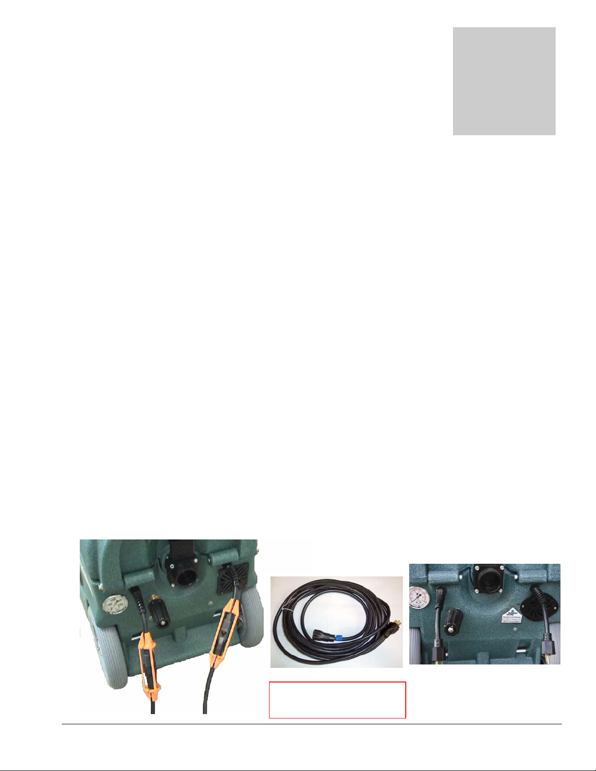
1. Electrical Cords:
Two 50’ power cords are supplied with the Olympus M1200. Cord #1 powers both vacuum motors; Cord
#2 powers the high pressure solution pump and the waste pump. The amperage required by each cord
requires that the two cords be plugged into separate circuits:
• Cord #1 (right side) will require a 20amp circuit to run both vacuums.
• Cord #2 (left side) can be plugged into a 15 amp circuit if Auto Pump-out is not used or a 20 amp
circuit if the Auto Pump-out is used.
20amp circuits are usually found in kitchens and bathrooms.
Plug the two power cords into two outlets from different circuits.
If you are not sure if you are connected to separate circuits, use a Breaker Buddy , included with your
machine, to test your circuits in the following manner:
• Plug the cords into the two outlets being tested, and then plug the two cords into your machine.
• If the green Breaker Buddy indicator light fails to light, you may be on the same circuit and must
select a different plug for one of the cords.
• If the green indicator light comes on, you are plugged into two different circuits, and may proceed
with your set-up procedure.
If a circuit breaker trips during operation, reset the breaker and move the cord to another outlet as needed.
Cord #2
Cord #1
Power Cord – AX33
50’ – 12 gauge M-F Plugs
8
Page 9
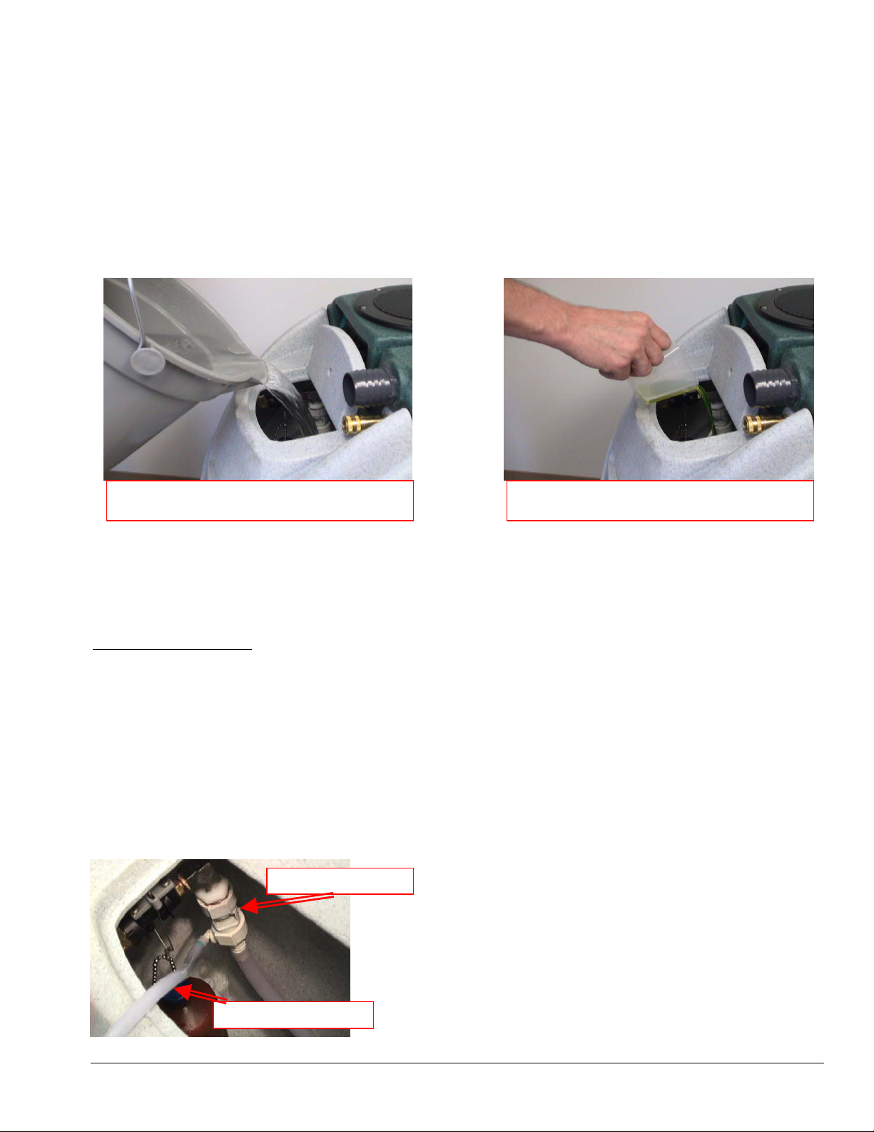
2A. Water Supply & Chemical Mixing– Manual Fill:
• Pour up to 12 gallons of hot water into the solution tank at the front of the machine. The water
temperature cannot exceed 180°F.
• Measure and add the appropriate amount of the desired liquid chemical to the water in the solution tank.
The amount of chemical will vary depending on the type of chemical used, the amount of water in the
tank, and the material being cleaned; consult the chemical packaging for specific mixture ratios.
• Powdered chemicals should be dissolved in water before adding to the water in the solution tank.
DO NOT RUN OUT OF WATER WHILE USING THE MACHINE! Ensure that the tank
contains enough water to complete each job. If the water level is low: stop cleaning, turn off the
pump, and refill the tank. Running the pump dry will damage the pump and void the warranty.
Pour appropriate amount of hot water into
Add appropriate amount of chemical to water
2B. Water Supply & Chemical Dilution – Auto-Fill:
• The chemical dilution rate is controlled by the metering tip, and the dilution rate can only be changed by
changing the metering tip (See “How to Change the Metering Tip” on Page 10 for instructions.)
Chemical Feed Setup:
• Remove the chemical feed hose from the solution tank.
• Place the end of the hose into a container of liquid chemical.
• If the tip is removed, and the proportioning system operated with no tip, the dilution rate will be 8:1 (the
equivalent to adding 16-1/4oz of chemical to each gallon of water.)
• The standard tip included with the M1200 is the turquoise tip with a dilution rate of 256:1. This means
that for each gallon of water flowing into the machine, 1/2 ounce of chemical will be added.
• If a fresh water rinse with no chemical is desired, simply leave the chemical feed hose inside the
solution tank.
Proportioning Valve
Chemical Feed Hose
9
Page 10
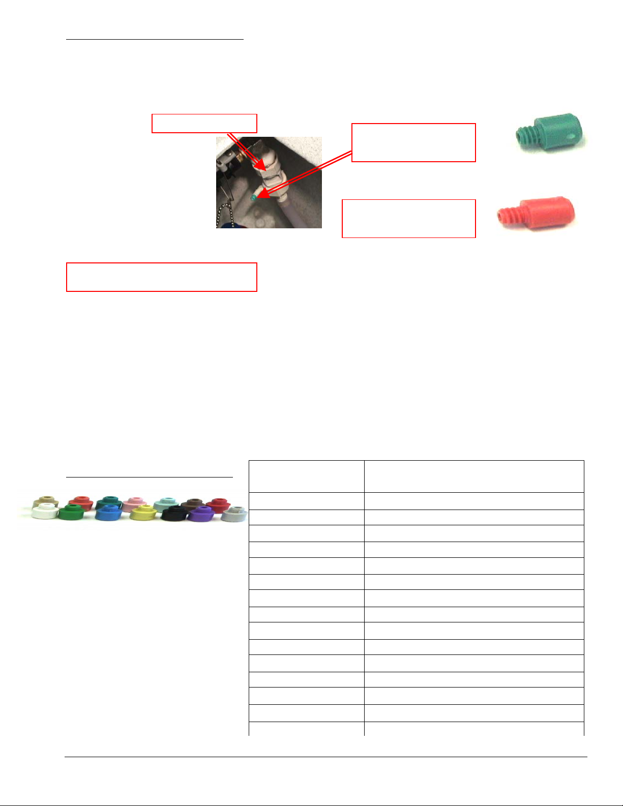
How To Change the Metering Tip:
• Remove the chemical feed hose from the barb on the side of the proportioning valve.
• Unscrew and remove the old tip.
• Screw in the proper tip for your chemical tip and place the hose back on the barb
Proportioning Valve
Turquoise Tip
Dilution 256 - 1
Red Tip
Dilution 85 - 1
Metering Tip Kit – PDE001
Metering Tip Kit (Hydro-Force Item# PDE001) contains 14 different colored metering tips, allowing
dilution rates from 11:1 up to 427:1. Refer to the chart below to select the tip that meets the dilution rate for
your chemical application.
• For example: if you require 1-1/2 ounces of chemical per gallon of water, change to the red metering tip
with the dilution rate of 85:1.
• The dilution rates are based on chemicals with water-like viscosity. Thicker (more viscous) chemicals will
dilute at a different rate.
• For powdered chemicals, a liquid concentrate must be made. Mix the concentrate according to the
manufacturer’s directions, and then select the appropriate metering tip.
• Contact your distributor or Hydro-Force if you have questions about your chemical.
Metering Tip Application Chart:
TIP
COLOR
CHEMICAL DILUTION RATES
OZ / GAL (RATIO)
TAN 0.30 (427:1)
ORANGE 0.40 (320:1)
TURQUOISE 0.50 (256:1)
PINK 0.75 (170:1)
LIGHT BLUE 1.00 (128:1)
BROWN 1.12 (114:1)
RED 1.50 (85:1)
WHITE 1.75 (73:1)
GREEN 2.00 (64:1)
BLUE 2.50 (51:1)
YELLOW 3.75 (34:1)
BLACK 5.00 (26:1)
PURPLE 8.50 (15:1)
GRAY 11.50 (11:1)
NO TIP 16.25 (8:1)
10
Page 11
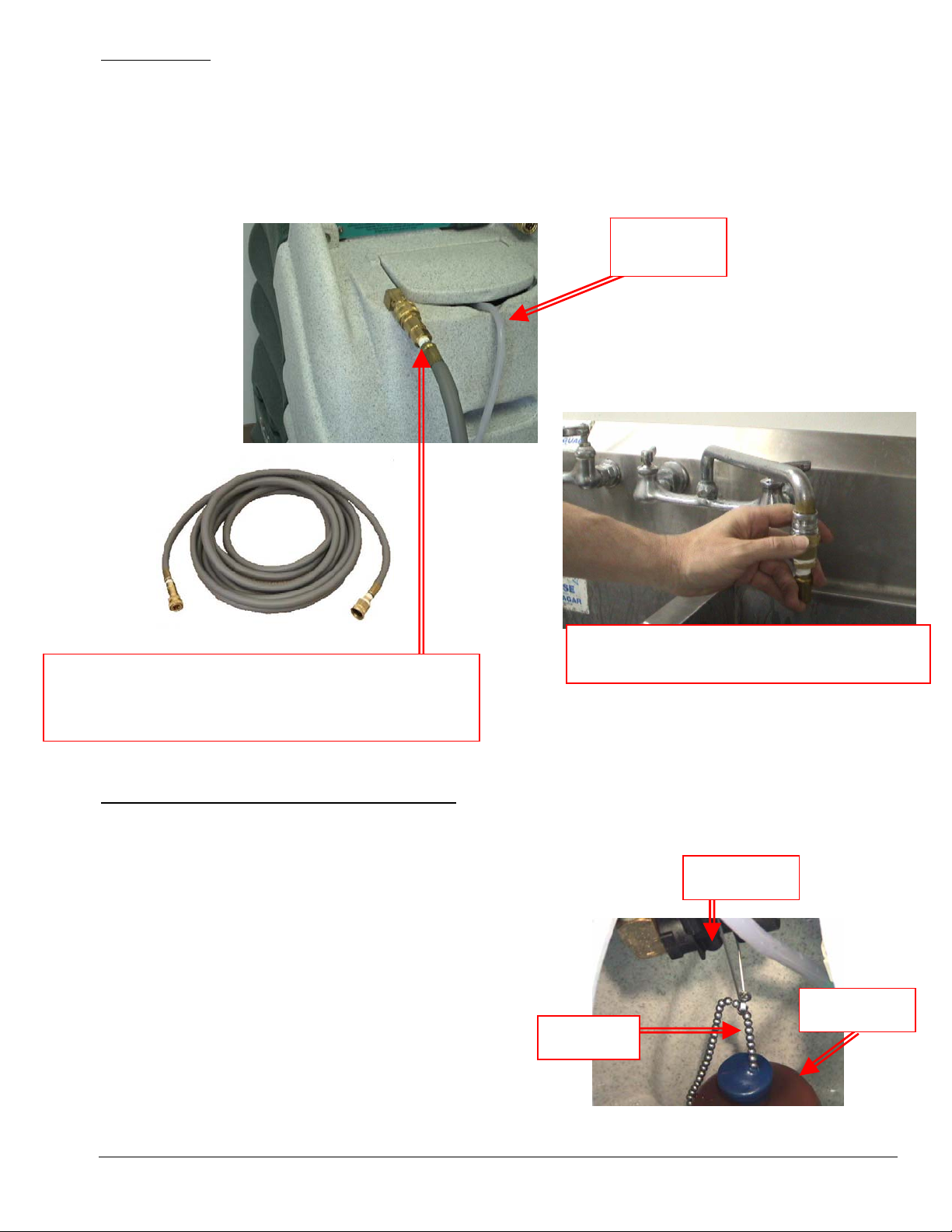
Water Supply:
• Once the correct metering tip is in place:
o Connect the Auto-Fill Water Supply Hose to the water inlet (the male quick-connect on the front
of the machine.)
o Connect the other end of the hose to a water faucet, and then turn on the water.
• Hot water can be used as long as the temperature does not exceed 180°F.
• Faucet adapter kits (Hydro-Force item #AX21 & AX22) are available that allow connection to different
types of faucets if needed.
Chemical
Feed Hose
Connect the Auto-Fill Water Supply Hose to Solution Inlet
(Male quick connect on the front of the machine.)
3/8” id X 25’ with F Quick Connect & F Garden Hose Fitting
Connect the Auto-Fill Water Supply Hose to a
faucet and turn on the water
To adjust the water level in the solution tank:
• Turn off the water supply.
• Adjust the length of the chain connecting the float bottle to the float valve.
• Snap the beaded chain off the connector on the valve.
Float Valve
o Move the bottle down to decrease the water level.
o Move the bottle up to increase the water level.
• Snap the chain back into the connector.
• Turn the water supply back on.
If the chemical is not drawing, or if the tank is not filling
or is overflowing, refer to the trouble shooting guide, or
contact your distributor for assistance.
Chain
Float Bottle
11
Page 12
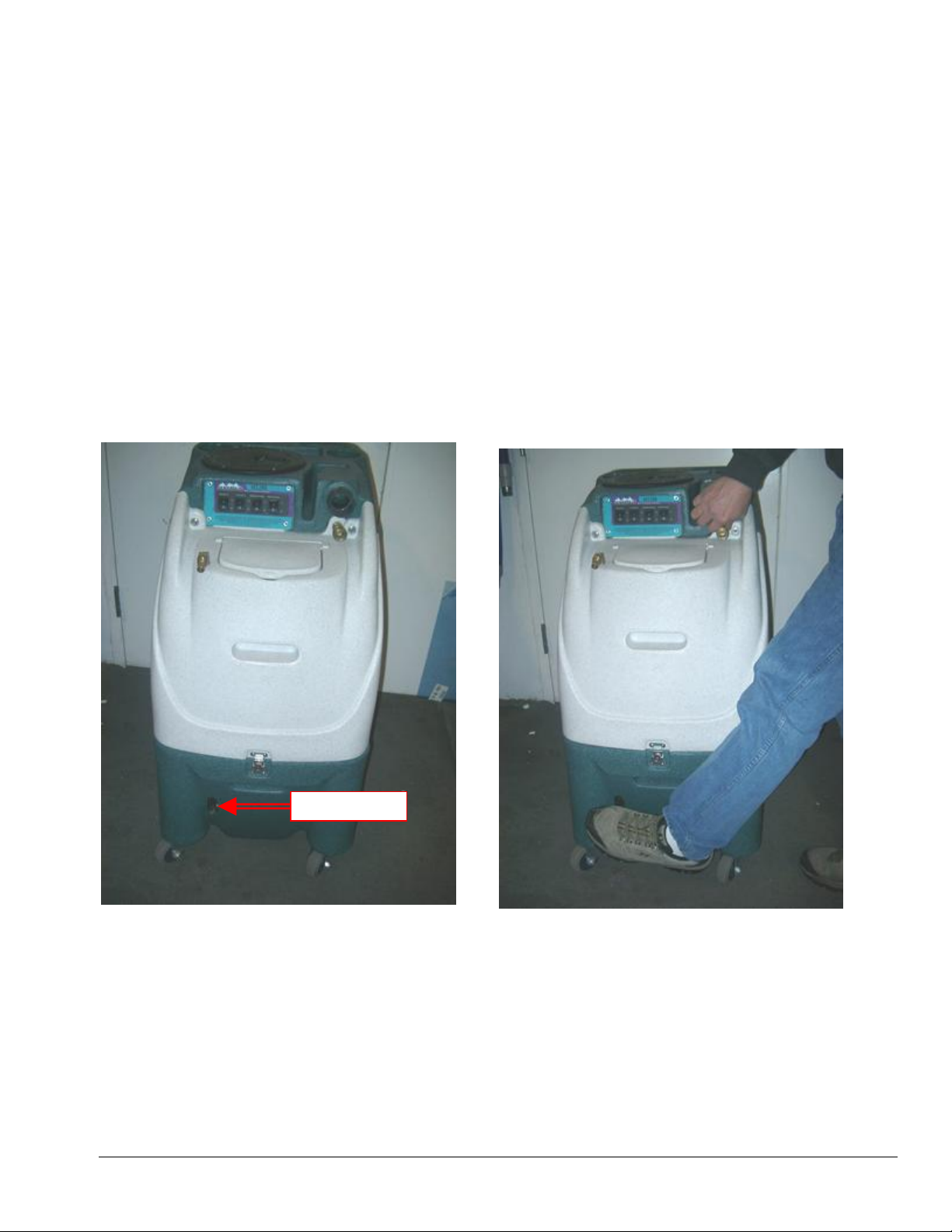
3. Priming the High-Pressure Pump:
Once water is in the solution tank, the high-pressure solution pump must be primed:
• There is a prime valve located on the front lower portion of the machine.
• Turn on both vacuums and the water pump. Press the priming lever for a few seconds while you
block off the vacuum inlet with your hand. The Vacuum will pull solution through the pump and
prime valve into the vacuum tank.
• Let off the prime valve and your pump is then primed. As long as there is solution in the tank the
pump should remain primed.
• After priming, turn off the pump and step on the primer valve to relieve the pressure in the line.
If the pump still does not prime, or if flow is low or unsteady, check the hose from the solution tank to the
pump (as well as the inline filter) for clogging, kinks, or restrictions. Clean or replace hose and/or filter
and repeat the priming procedure.
If you are having trouble with the pump, refer to the trouble shooting guide or contact your distributor for
advice or assistance.
Prime Valve
12
Page 13
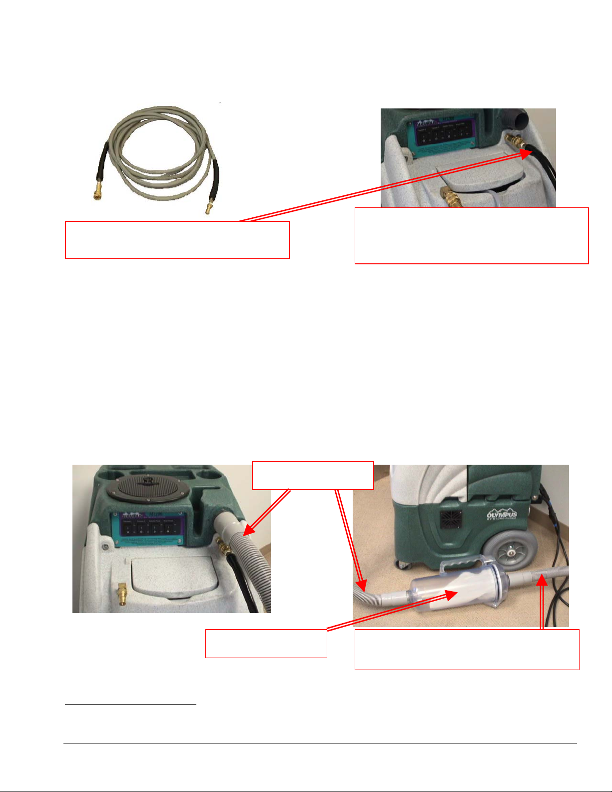
4. Connection of Solution Hose:
Connect the high pressure solution hose to the solution outlet (female quick connect on the front of the
machine). Connect the other end of the hose to the male quick connect on the cleaning tool. When you are
ready to start cleaning, turn the solution pump switch to the ON position
HP Solution Hose Assembly – AH79D
1/4” id X 25’ with M-F Quick Connects
Connect the male end of the HP Solution Hose
Assembly to the female solution outlet fitting on
the machine. Connect the female end to the
cleaning tool.
5. Connection of Vacuum Hoses:
There are three components used to connect the cleaning tool to the vacuums and recovery tank:
1. A short 4’ vacuum hose: Connected to the vacuum barb on the front of the machine and to the
outlet side of the Hydro Filter.
2. A Hydro Filter
3. A 25’ Vacuum Hose: The 2” cuff on the 25’ vacuum hose is connected to the inlet side of the hydro
filter. The other end with the 1-1/2” cuff is connected to the cleaning tool.
When ready to begin cleaning, turn both vacuum switches to the ON position. While the M1200 can be
operated with only one vacuum for cleaning delicate fabrics, in most situations you will turn both vacuum
switches ON.
Short Vacuum Hose
-
”
’
”
Hydro-Filter – AC11
Vacuum Hose
1-1/2” x 25’ with 2” & 1-1/2” cuffs
Optional Accessories
Foam Downer (included):
A key problem with portable extractors is that they have small tanks where foam dissipates slowly. If you
have had issues with foam or are anticipating foaming problems, you will want to setup your Foam Downer.
13
Page 14
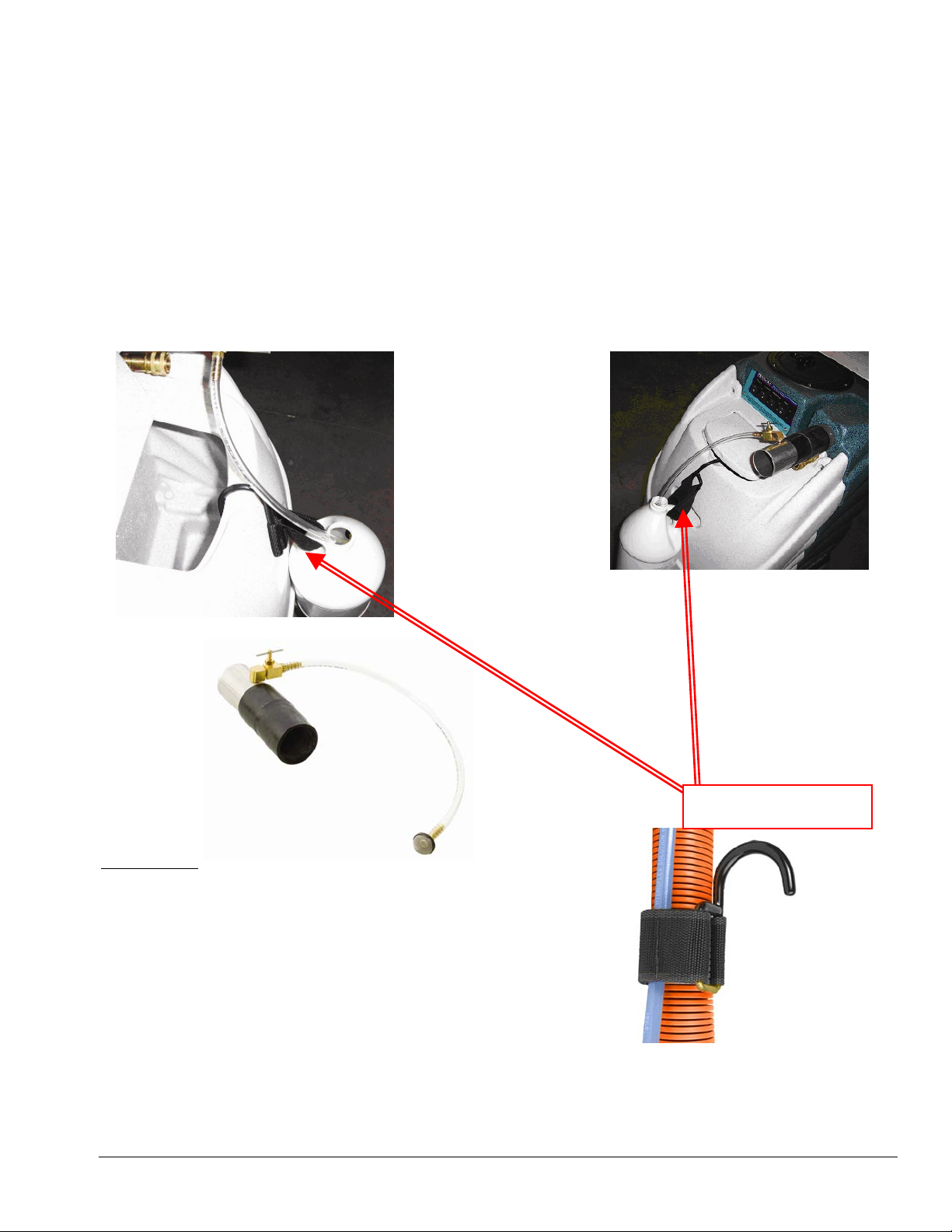
Foam can decrease vacuum lift and eventually ruin the vac motor. The Foam Downer kills foam as waste
water enters the machine. It uses a hook to hang a jug of liquid defoamer from your portable. Foam Downer
injects defoamer into the vac hose. Your portable suffers no power loss from foam and your motor suffers
no damage.
• Mounts and is ready to use in seconds
• Uses defoamer very economically
• NO LABOR is involved to spray or spread defoamer – it’s all automatic
• Keeps silicone defoamers off the floor where they can deposit and cause soiling and problems later
The Foam Downer is an attachment that draws a small amount of defoamer in a constant slow flow into the
waste tank of Olympus through its vacuum system. We recommend diluting a gallon at 1 to 32 and open the
needle nose valve up one half turn as a starting place. If not sufficient you can decrease the dilution, or open
up the valve more. At one half turn it will take approximately one half hour to drain the gallon of diluted
defoamer. The hose hook holds the gallon of diluted defoamer on the front of the Olympus as shown in the
pictures.
Hose Hook – AH95
Hose Hook:
Not only is this necessary for your Foam Downer, you won’t
believe how helpful they can be to keep your hoses off the ground.
14
Page 15

6. Connection of Pump-out Hose:
The pump-out hose is a 50’ section of 3/4” garden hose.
• Remove the cap from the pump-out outlet fitting on the back of the machine.
• Connect the pump-out hose to the outlet fitting.
• Place the other end of the hose in a commode or drain connected to the sanitary sewer system.
• Secure hose end to prevent movement during pumping.
Use defoamer to prevent foam build-up in recovery tank during cleaning and to keep foam/moisture
from entering vacuums.
When ready to begin cleaning, turn the waste pump switch to the ON position.
• Do not turn on waste pump switch unless pump-out hose is connected and has been routed
to a proper drain.
Pump-out Hose – AH65
3/4” id X 50’ with M-F Garden Hose Fittings
Connect the Female Garden Hose Fitting end of the
Pump-out Hose to the outlet fitting on the back of the
recovery tank. Place the other end of the pump-out
hose in a sanitary drain.
If not using the waste pump-out, the pump-out hose does not need to be connected. When the recovery tank
fills during cleaning, the float ball assembly in the vacuum inlet filter will rise and will automatically shut off
the vacuum air flow to prevent the recovery tank from overfilling and waste water from getting into the
vacuums. When this occurs:
• Immediately shut off the vacuum switches.
• Drain the recovery tank.
o Turn off the pump switch while draining the tank.
o Turn pump switch back upon resumption of cleaning.
• Close the drain valve and turn the vacuum switches back on when ready to resume cleaning.
If the pump-out or vacuum shutoff is not working properly, refer to the trouble shooting guide or contact
your distributor for advice or assistance.
Float Shutoff Assembly – NM5037
15
Draining the Recovery Tank
Page 16

7. Pressure Adjustment:
When the high-pressure solution pump is on and primed, pressure will show on the gauge only while the tool
is being sprayed. When the tool is sprayed the gauge will display the pressure being delivered to the tool.
When the tool is not being sprayed the gauge will return to zero.
• To decrease the pressure, turn the black knob on the pressure regulator to the left (counter-
clockwise.)
• To increase the pressure, turn the black knob on the pressure regulator to the right (clockwise.)
• To adjust pressure to your tool and surface requirements:
o Spray the tool.
o Check the pressure on the gauge.
o Re-adjust as needed to set the machine at the desired pressure.
o Choose the pressure setting that best meets your type of cleaning.
To increase the solution pressure, turn the
regulator knob clockwise.
The maximum pressure setting is 1200psi;
however, the highest pressure attained is
dependent on the amount of water flow at the
tool:
• Smaller jets and lower flow will allow for
higher pressure at the tool.
• Larger jets and higher flow will lower the
maximum pressure attained at the tool.
The desired setting will depend on the type of
cleaning and tool used. For example:
• Carpet Cleaning with 2-jet AW29 wand: 400psi
• Tile Cleaning with SX-12: 1000psi
If adjusting or maintaining pressure becomes a
problem, refer to the trouble shooting guide or
contact your distributor for advice or assistance.
To decrease the solution pressure, turn the
regulator knob counter-clockwise.
Pressure gauge
16
Page 17

Shutdown Procedures:
• If using the auto-fill system, turn the water supply off before finishing each job. This will allow use of the
water and chemical already in the tank, and will reduce the amount of excess water to be disposed of later.
• When finished cleaning, turn off all switches.
• If the auto-fill system was used and there is still water in the solution tank, push the float down to release
the water inlet hose pressure before disconnecting the hose from the faucet. Disconnect the water inlet
hose from the quick-connect on the front of the machine.
• Disconnect the solution hose and vacuum hose from the cleaning tool. Pull valve trigger to release
pressure from the hose before disconnecting solution hose from cleaning tool.
• Disconnect the Hydro-Filter from the vacuum hoses and clean the
filter as needed. Replacement filter bags are available (AC11A.)
• Disconnect the vacuum hose and solution hose from the machine.
• If water remains in the solution tank, use the short
vacuum hose and vacuum the excess water from the tank.
• If the auto-fill system was utilized, place the chemical feed
hose back into the solution tank.
• If the waste pump-out system was used:
o Turn the waste pump switch “on” to pump out any remaining water from the recovery tank.
o Turn switch off, remove the pump-out hose from the outlet fitting and replace the cap.
o Roll up hose toward drain to remove remaining water from hose.
o Connect ends of hose together to prevent dirty water from dripping from hose during transport.
• Disconnect the power cords from the outlets and from the machine.
• Remove the float shutoff assembly from
the recovery tank and clean filter as needed.
Replace shutoff assembly and tank lid.
• Drain any remaining water from the recovery tank
and dispose in sanitary drain. Do not use the same
bucket to drain the tank that you use to fill the tank.
• Roll up all hoses and cords.
Collect and store extractor, all tools, and accessories.
17
Page 18

Section
Troubleshooting
2
Troubleshooting –
Olympus M1200
Problem Cause Solution
Machine not Building circuit breaker tripped. Reset breakers or move cords to other outlets
turning on - Faulty power cord Replace cord
No power Faulty switches or internal wiring Check wiring & test switches - Repair as needed *
Solution
Pump Building circuit breaker tripped. Reset breakers or move cords to other outlets
not running Faulty power cord Replace cord
Faulty switches or internal wiring Check wiring & test switches - Repair as needed *
Pump motor breaker tripped Push in reset button on pump motor
Pump motor faulty Replace pump motor
Pump seized - trips breaker Repair or replace pump head & bearing - Check motor
Check jets size & flow rates use smaller jets or lower
Low Solution Jets too large for pressure desired
Pressure
and/or Jets worn allowing too much flow Replace jets
Pulsation Solution inlet filter plugged Clean or replace filter
Hose from solution tank restricted Repair or replace hose
Pump intake hose or fittings
Pressure regulator sticking Lube o-rings on regulator shaft
Pressure regulator faulty Repair or replace pressure regulator
Solution tank empty Add water to tank - Check & repair auto fill assembly
Pump not primed Perform pump priming procedure
Pump faulty Repair or replace pump
Pressure Gauge faulty Replace gauge
Tool valve faulty Repair or replace valve
Quick connects or hoses restricted Clean out or replace quick connects and/or hoses
Can't connect Pressure in lines Release pressure
solution hose Quick connects faulty Replace quick connects
to machine Wrong style/size quick connects Replace quick connects to match connects on machine
experienced service technicians.
If you are not experienced in checking electrical wiring contact your nearest authorized service
center to perform tests and repairs to wiring and switches.
leaking
Filter screen or jets plugged on
tool Clean out filter or jets
* To reduce the risk of fire electrical shock or injury repairs to wiring should only be performed by
pressure
Repair or replace hose. Tighten clamps or replace fittings
18
Page 19

Problem Cause Solution
Pump-out Building circuit breaker tripped. Reset breakers or move cords to other outlets
not working Faulty power cord Replace cord
Faulty switches or internal wiring Check wiring & test switches - Repair as needed *
Pump-out pump faulty Replace pump-out pump
Clean pump-out - Keep recovery tank clean - Use Hydro Pump-out pump clogged
Outlet check valve stuck Clean or replace check valve
Discharge hose restricted Un-kink, clean out or replace hose
Float switch stuck Clean switch make sure float slides up & down easily
Float switch faulty Replace float switch
Vacuum Building circuit breaker tripped. Reset breakers or move cords to other outlets
Motor Faulty power cord Replace cord
not running Faulty switches or internal wiring Check wiring & test switches - Repair as needed *
Vacuum motor faulty Replace vacuum motor
Loss of Vacuum motor faulty Replace vacuum motor
Vacuum Vacuum motor gasket damaged Replace gasket
Recovery tank lid gasket damaged Replace gasket
Drain valve open Clo se valve
Drain valve leaking Repair or replace drain valve
Vacuum motor hoses loose /
leaking Reconnect or replace vacuum motor hoses
Vacuum hose or tool clogged Clean out vacuum hoses and tool
Vacuum hoses or cuffs leaking Replace vacuum hoses, cuffs & connectors as needed
Recovery tank full Drain tank
Float shutoff filter clogged Clean float shutoff filter
Ball stuck in float shutoff Repair or replace float shutoff
Recovery tank damaged Replace recovery tank
Chemical not Solution tank not filling Check & repair auto fill assembly
feeding Chemical hose restricted Un-kink, clean out or replace hose
Filter screen plugged Clean or replace filter
Wrong size metering tip Change metering tip
Chemical proportioner faulty Replace chemical proportioner
Check valve in filter faulty Replace filter
Tool won't Jets clogged Clean out or replace jets
spray - low or Inline filter clogged Clean out or replace filter
uneven spray Jets worn Replace jets
Jets not aligned properly Re-align jets
Tool valve faulty Repair or replace valve
Quick connects or hoses restricted Clean out or replace quick connects and/or hoses
*
To reduce the risk of fire electrical shock or injury repairs to wiring should only be performed by
experienced service technicians.
If you are not experienced in checking electrical wiring contact your nearest authorized service
center to perform tests and repairs to wiring and switches.
Filter
19
Page 20

Problem Cause Solution
Solution Tank Water source turned off Turn on faucet or find other water source
not filling Float not on valve arm Reconnect float to valve arm - Adjust to proper height/level
Float valve faulty Repair or replace float valve
Water hose restricted Un-kink, clean out or replace hose
Quick connects faulty Clean out or replace quick connects
Solution tank Float too heavy/ Filled with water Replace float
overflowing Float & chain tangled Make sure float chain free & hanging properly
Float too high Adjust chain to set float at proper level
Float valve faulty Repair or replace float valve
*
To reduce the risk of fire electrical shock or injury repairs to wiring should only be performed by
experienced service technicians.
If you are not experienced in checking electrical wiring contact your nearest authorized service
center to perform tests and repairs to wiring and switches.
• Contact your distributor for additional troubleshooting
assistance, to order parts, or for advice and assistance in
performing necessary repairs.
20
Page 21

g
g
M1200
Solution Flow Path
Outlet Quick
Connect
Denotes
incoming water
flow
Solution Tank
Filter
e
Pump – AP48
Gau
Denotes Water
flow in high
pressure hose
Float Valve
Denotes by-pass
water flow from
pressure regulator
Inlet Quick
Connect
Chemical Ju
Pressure Regulator /
Unloader – PT019
Denotes
Chemical flow
21
Page 22

M1200
SW
TCH
Wiring Diagram
I
FLOAT
Waste Pump
BLACK
BLACK 12 GA
Solution
Pump
YELLOW
BLACK
SOLUTION
PUMP
RED
BLACK
VACUUM
#2
2-Stage
BLACK 12 GA
Vacuum #1Vacuum #2
BLUE
BLACK
VACUUM
#1
3-Stage
BLACK
CORD #1
WHITE
WHITE BLUE BROWN
WASTE
PUMP
BLACK
TO COMMON GROUND FOR ALL COMPONENTS
GREEN
WHITE
WHITE
TO COMMON GROUND FOR ALL COMPONENTS
GREEN
CORD #2
BLACK
22
Page 23

23
Page 24

OLYMPUS SWITCH PANEL:
Vacuum #1 – Power from Cord #1.
When the switch is turned to the ON
position power is supplied to the vacuum
motor. (3-Stage Vacuum)
Vacuum #2 – Power from Cord #1.
When the switch is turned to the ON
position power is supplied to the vacuum
motor. (2-Stage Vacuum)
Solution Pump Switch – Power from Cord #2.
When the switch is turned to the ON position
power is supplied to the solution pump motor.
When not using solution (Extracting Only) do not
turn this switch ON.
Waste Pump Switch – Power from Cord #2.
When switch is turned to the ON position,
Waste Pump operation is controlled by the Float
Switch in the Recovery Tank. Pump will remain
off until water level rises to the point at which
the float switch will turn the Waste Pump ON.
Do not turn Waste Pump Switch ON unless a
hose is connected to the Pump-out Outlet port.
24
Page 25

Section
3
Maintenance
Proper maintenance is required to keep the M1200 operating properly, prevent
downtime and to extend the life of your equipment.
WARNING: Disconnect electrical power before performing any service or
maintenance inside machine base or before testing or repairing switches or power
cords. Failure to do so may result in severe personal injury or death.
OPERATION INTERVAL Page #
CLEAN CHEMICAL FEED FILTER & FOOT VALVE Daily – After Each Job 24
CLEAN VACUUM SHUTOFF ASSEMBLY SCREEN Daily – After Each Job 24
CLEAN HYDRO-FILTER Daily – After Each Job 25
RINSE OUT RECOVERY TANK Daily 25
CLEAN WASTE PUMP-OUT PUMP Daily 26
FLUSH SOLUTION TANK AND PUMP Daily 26
CLEAN PUMP-INLET FILTER Weekly – As needed 27
FLUSH CHEMICAL SYSTEM Monthly 28
LUBRICATE PRESSURE REGULATOR O-RINGS Monthly 29
CLEAN DRAIN VALVE As needed 31
STORAGE PREP – FREEZE PROTECTION As needed 32
25
Page 26

CLEAN CHEMICAL FEED FILTER & FOOT VALVE:
The Filter & Foot Valve is on the end of the chemical feed hose that is placed in the chemical jug as part of
the chemical feed system.
Regularly examine the filter and clean as needed.
To test the Foot Valve:
• Remove the Filter & Foot Valve from the end of the chemical feed hose and rinse in fresh water.
• Blow through the valve from the filter side of the barb.
o If the Foot Valve is functioning, air should move freely from the filter side, but will not flow from
the barb side of the filter.
o If valve is not functional, clean or replace as needed.
Heavy chemical build-up can be removed with a mild acid rinse and/or the use of a brush and compressed
air.
Chemical Feed Hose
Filter & Foot Valve
PDE100-11P
Flow Direction
Flow Direction
CLEAN VACUUM SHUTOFF ASSEMBLY SCREEN:
Inside the recovery tank, on top of the stand pipe, is the Vacuum Shutoff Assembly. It functions to prevent
debris and water from being sucked into the vacuum motors. Operating the M1200 without the Vacuum
Shutoff Assembly or with a poorly maintained assembly will greatly decrease the life of the vacuum motors
and will void the warranty.
If debris builds up on this filter, it will reduce the vacuum air flow and may cause a significant decrease in the
rate of water recovery. If debris prevents the float ball from moving or seating inside the assembly, it may not
stop the airflow when the tank fill with water, and the water will be sucked into the vacuums and blown out
the exhaust. Use defoamer to prevent foam or moisture from entering vacuums.
To clean:
• Twist to loosen and pull the assembly off of the stand pipe.
• Pull fibers and lint off and rinse with clean water.
• Push the assembly back onto the stand pipe and replace the recovery tank lid.
Vacuum Shutoff Assembly
NM5037
26
Page 27

CLEAN THE HYDRO-FILTER:
Build-up of debris in the filter bag of the Hydro-Filter will reduce the vacuum air flow and may cause a
significant decrease in water recovery. A torn filter bag will allow debris past the filter and into the recovery
tank. This debris can clog the Waste Pump and the Vacuum Shutoff Assembly. The Hydro-Filter must be
examined and cleaned regularly to keep the M1200 functioning properly:
• Push the latch lever and open the Hydro-Filter lid.
• Remove the filter bag. Examine the bag and clean or replace as needed.
• Rinse the body of the Hydro-Filter with clean water.
• Examine the o-ring seal and replace as needed.
• Re-install the new or cleaned bag.
• Close lid and secure latch.
FILTER BAG – AC11A
Repair parts are available for the Hydro-Filter:
Filter Bag: AC11A
Parts Kit: AC11B – (Includes Latch, O-ring & screws.)
Lid: AC11D
LID – AC11D
O-RING
LATCH
FILTER BODY
RINSE OUT RECOVERY TANK:
Build-up of fine silt and debris can damage the Waste Pump and Drain Valve. Clean out the tank on a regular
basis to extend the life of these components as well as keep the tank and machine smelling better.
• Remove the recovery tank lid and open the drain valve.
• Place a bucket under the drain valve.
• Use a hose to rinse the dirt and debris out of the recovery tank.
• Close the drain valve and spray the tank with a deodorizer or disinfectant.
• Proceed to Waste Pump Cleaning and replace the recovery tank lid.
• Dispose of the dirty water and debris.
27
Page 28

CLEAN WASTE PUMP-OUT PUMP:
Build-up of fine silt inside the Waste Pump can clog the pump even if the pump is not used, so this
maintenance procedure should be performed regardless of whether the Waste Pump has been used.
• After cleaning out the recovery tank, remove the cap and connect the Pump-Out hose to the Waste
Pump outlet fitting on the back of the machine; run the hose to a drain..
• With Cord #2 plugged in, turn the Waste Tank switch to the ON position.
• Use a hose to fill the recovery tank to the point where the float switch turns the Waste Pump ON.
• Let the pump run until it pumps the level down to the point when the float switch shuts off the Waste
Pump.
• Unplug the cord and turn the Waste Pump switch OFF.
• Open the drain valve and drain out the remaining water.
• Close the drain valve, replace the recovery tank lid, and dispose of the dirty water and debris.
FLUSH SOLUTION TANK AND PUMP:
• Pour two or three gallons of clean water into the solution tank.
• With Cords #1 & #2 plugged in, connect the pump prime hose to the
solution outlet female quick connect.
• Direct the end of the prime hose into the recovery tank vacuum barb.
• Turn one or both of the vacuums ON and turn the solution pump ON.
• Let the pump run until most of the water has been pumped out of the
solution tank. Do not let the pump run dry. Turn the pump OFF
before the water gets to the bottom of the tank.
• Turn the vacuums OFF and disconnect the prime hose.
• Place a bucket under the drain valve; open the drain valve to drain the water out of the recovery tank.
• Close the drain valve and dispose of the water.
If there is a heavy chemical build-up in the machine, hoses, or tools, a mild acid can be added to the rinse
water in the previous procedure (REFER TO PHOTOS ON FOLLOWING PAGE.)
• After the pump has been primed, turn the solution pump switch OFF and turn the vacuums OFF.
• Remove the prime hose and connect the HP solution hose and tools.
• Turn the solution pump ON and direct the tool spray into a bucket. Let the pump run until most of
the water has been pumped out of the solution tank. Do not let the pump run dry. Turn the pump
OFF before the water gets to the bottom of the tank.
• Disconnect the solution hose and tool.
• Use the 4’ short section of vacuum hose to vacuum the remaining acid solution out of the solution
tank.
• Pour two or three gallons of clean water into the solution tank.
• Connect the pump prime hose to the solution outlet female quick connect.
• Direct the end of the prime hose into the recovery tank vacuum barb.
• Turn one or both of the vacuums ON and turn the solution pump ON. Let the pump run until most
of the water has been pumped out of the solution tank. Do not let the pump run dry. Turn the
pump OFF before the water gets to the bottom of the tank.
• Turn the vacuums OFF and disconnect the prime hose.
• Place a bucket under the drain valve and open the drain valve to drain the water out of the recovery
tank.
• Close the drain valve and dispose of the water.
28
Pour 2 or 3 gallons of clean
water into Solution Tank
Page 29

FLUSH SOLUTION TANK AND PUMP: (continued from previous page)
Direct the end of the prime hose into
the recovery tank vacuum barb
Vacuum acid solution out of
Solution Tank
CLEAN PUMP INLET FILTER
A restricted Pump Inlet Filter can prevent the solution pump from providing adequate pressure for cleaning.
A restriction or air leak on the pump inlet can also damage the solution pump check valves and plunger seals.
CAUTION: Before proceeding with this procedure, make sure both power cords are disconnected.
• To examine the filter, release the latch on the front of the machine and tilt the tanks off of the base
assembly. Support the tanks with a chair, bucket or box while working inside the base.
• The filter is in the clear 1/2” ID hose from the solution tank to the inlet port on the solution pump.
• Grasp the clear plastic filter cap and unscrew the cap from the black plastic filter body by turning
counter-clockwise.
• Remove the stainless steel filter screen and clean as needed.
• Examine the cap and body for cracks and replace filter as needed. (Replacement Filter: PPU6175)
• Check the gasket for nicks or tears and replace filter as needed.
• Reassemble filter and check hose clamps and tighten as needed.
• Tilt the tanks back onto the base and secure the latch.
Latch
Solution Tank
INLINE FILTER
PPU6175
Base
29
Page 30

FLUSH CHEMICAL SYSTEM:
Chemical build-up in the chemical system can prevent the system from
drawing chemical.
• Rinse the chemical system with fresh water (For heavy chemical build-
up, a mild acid can be added to the rinse water.)
• Remove the chemical feed hose from the solution tank and place the
end of the hose in a bucket of fresh water or mild acid solution.
• Connect the Auto-Fill Water Supply Hose to the water inlet (male quick connect) on the front of the
machine.
• Connect the other end of the hose to a water faucet and turn on the water. Let the water flow into the
tank until you are sure the rinse solution has been drawn through the proportioner and mixed with the
incoming water. The metering tip can be removed from the proportioner to speed up the process.
• Once the rinse solution has been drawn through the proportioner, turn off the water faucet and
disconnect the Auto-Fill Water Supply Hose.
• Plug in Cord #1, connect the short 4’ vacuum hose to the vacuum barb, turn on one or both vacuums,
and use the short vacuum hose to remove the water from the solution tank.
• When the solution tank has been emptied, turn off the vacuums and unplug the power cord.
• Place a bucket under the drain valve and open the drain valve to drain the water from the recovery tank.
• Close the drain valve and dispose of the water.
Place Chemical Feed Hose into
Connect Auto-Fill Water Supply
Hose to machine and faucet
Vacuum water out of Solution
Tank
30
Drain water from Recovery
Tank
Page 31

LUBRICATE PRESSURE REGULATOR O-RINGS:
To maintain consistent adequate pressure delivery to the cleaning tool, the o-rings on the stem of the M1200
pressure regulator must be lubricated regularly.
1. Remove nut from the end of the regulator stem.
2. Remove the black knob from the regulator stem.
3. Remove the spring plate, spring, and spring washer from the
regulator stem.
4. Remove the jam nut and washer from the shoulder of the
regulator stem retainer. (The set point nuts do not need to be
removed.)
Set Point Nuts
Spring
Washer
Stem
Spring Plate Spring
5. Release the latch on the front of the machine and tilt the tanks off of
the base assembly. Support the tanks with a chair, bucket, or box
while working inside the base.
6. Disconnect the vacuum hose from the vacuum manifold and move it
out of the way to gain access to the regulator.
7. Pull the regulator assembly from the base wall opening (back into the
base) to access the regulator. A hose may have to be disconnected to
move the regulator into a better working position.
8. Hold the body of the regulator with a wrench or vice-grip pliers. Use
another wrench to loosen and remove the stem retainer, then
remove the stem assembly from the body of the regulator.
Loosen & remove Stem
Lubricate Stem O-rings with synthetic
9. Use a synthetic grease with Teflon such as Ultra-Slick or Super-Lube to lubricate the o-rings on the
regulator stem.
Nut
Jam Nut
LATCH
Black Knob
Washer
31
Page 32

10. Apply thread sealant to the threads of the stem retainer and screw the retainer back into the regulator
body. Tighten using wrenches.
Apply thread sealant to stem
retainer
Screw stem retainer back into
regulator body
11. Place the regulator back into the opening on the base wall. Reconnect any hoses which were removed to
access the regulator. (Use thread sealant when reconnecting hoses.)
12. Reconnect vacuum hose to vacuum manifold.
Regulator – Inserted into
opening on base wall
Vacuum Hose – Connected to
Vacuum Manifold
13. Close tanks back onto base and secure latch.
14. Place washer and jam nut back onto shoulder of regulator and tighten to secure regulator to base wall.
15. Replace spring washer, spring, and spring plate back onto regulator stem.
16. Screw black knob back onto regulator stem.
17. Screw nut back onto regulator stem. Do not screw nut on too far, as the nut may interfere with the
movement of the regulator knob and prevent the knob from being backed out when trying to adjust
regulator to lower pressures.
32
Page 33

CLEAN RECOVERY TANK DRAIN
Debris and sand accumulation in the drain valve can damage the valve or prevent it from closing completely.
This will result in dirty water leaking from the valve. Use of the Hydro-Filter and regular cleaning of the
recovery tank will help prevent this, but occasionally the drain valve will require cleaning or replacement.
Drain the recovery tank before attempting to service the drain valve.
• Unscrew the nuts and remove the four bolts holding the valve assembly to the flange attached to the
recovery tank. Unless the flange is damaged, it does not have to be removed from the tank, even when
replacing the drain valve.
• Separate the valve body, outlet adapter and gaskets from the flange.
Remove four bolts holding valve
assembly to flange fitting
VALVE BODY
DRAIN VALVE – PEA11
GASKET – NM3019
• Examine the valve body for wear. Check the valve slide
for deep scratches. Deep scratches will allow water to flow
past gaskets and leak from valve. Replace valve if needed.
• Examine the gaskets and replace if cut, torn or deformed.
• Raised, rounded side of gasket goes toward valve slide.
Larger flat sides seat on ring on flange and outlet adapter.
Sand and debris will collect in the bottom of the valve
body and prevent the slide from going down and seating
properly.
• Clean debris out as needed so slide can move to bottom.
• Rinse valve body and reassemble valve body, gaskets and
outlet adapter, and place assembly back onto flange fitting.
• Replace four bolts and tighten evenly to secure assembly
to flange. Do not over-tighten bolts.
Unless damaged or leaking between
tank and flange, the flange fitting does
not have to be removed
Clean debris from slot in bottom of valve body.
FLANGE FITTING
OUTLET
33
Page 34

Storage Prep and Freeze Protection Procedures:
Your Olympus M1200 must be protected from freezing. Freezing can cause serious damage to the pump,
pump-out, auto-fill float valve, and any other component containing water. If the M1200 is transported or
stored in freezing temperatures, the following procedures should be performed.
ALSO, if the M1200 is stored for an extended period of time, the following procedure should be performed
to prevent the pump seals from drying out.
1. In a separate container mix 1/2 gallon of water with 1/2 gallon of automotive radiator anti-freeze.
(Ethylene glycol type). Mix well and pour into the solution tank.
2. Connect the pump prime hose to the solution outlet (female quick connect) and perform the pump
priming procedure, directing the flow back into the solution tank. When the pump is primed, turn the
pump off and disconnect the priming hose.
3. Connect the HP solution hose to the solution outlet (female quick connect.) Connect the opposite end of
the HP solution hose to the Auto-Fill inlet (male quick connect.) Leave the chemical feed hose in the
solution tank and ensure the check valve filter is submerged in the anti-freeze solution. To speed the
process the metering tip can be removed. Turn the pressure regulator knob counter-clockwise to lower
the pressure to 100psi or lower
CAUTION: Applying high pressure (over 100psi) to the Auto-Fill system will cause damage to
the Float valve and chemical proportioning mechanism.
4. Turn the solution pump switch to the ON position. Allow the anti-freeze to circulate for 5-10 minutes.
Mix and add more anti-freeze solution as needed. Make sure end of chemical feed hose stays submerged
in the anti-freeze solution. This will assure that the anti-freeze will be drawn into the proportioning valve.
5. Connect any cleaning tools that will be stored with the M1200. Direct tool spray back into the solution
tank or into a bucket. Repeat for all tools to be protected.
6. Turn the solution pump switch to the OFF position.
7. Use the 4’ short section of vacuum hose to vacuum the remaining anti-freeze solution out of the solution
tank and bucket.
8. Remove the cap from the waste-pump out outlet fitting on the back of the machine. Connect a hose to a
drain or hold a bucket up to the fitting to catch the pump-out flow.
9. Remove the lid from the recovery tank. Turn the Waste Pump switch to the ON position and lift the float
switch to engage the pump-out. Lower the float and turn off the Waste Pump Switch as soon as you see
anti-freeze flowing from the outlet fitting or hose.
10. Drain the remaining anti-freeze solution from the recovery tank and the machine is ready for storage.
RETURNING THE M1200 TO SERVICE AFTER STORAGE OR
FREEZE PROTECTION:
To return the M1200 to service, the anti-freeze must be flushed from the machine. Flush the anti-freeze out
of the machine by repeating the procedures above using fresh water in place of anti-freeze.
34
Page 35

Parts
Replacement parts available for repair of your M1200.
M1200 PUMP – AP48
PARTS ASSEMBLY
Section
3
KIT C – PT046
KIT A – PT042 KIT B – PT044
35
Page 36

PUMPTEC #356 PUMP – AP48
ITEM DESCRIPTION QTY PART NUMBER
1 PLUNGER 1 0311-0006-0002
2 PLUNGER GUIDE 2 0311-0009
3 O-RING FOR PLUNGER GUIDE 2 C0100-1124
4 U-CUP 2 C0220-1075
5 U-CUP BACKING RING 2 0311-0011
6 PUMP HEAD 2 0356-0002-0001
7 PUMP MANIFOLD 1 0356-0004-0001
8 VALVE ASSEMBLY 4 0205-0012
8A VALVE SEAT (Part of #8 - Valve Assembly) 4 0205-0017
8B VALVE POPPET (Part of #8 - Valve Assembly) 4 0205-0013
8C VALVE SPRING (Part of #8 - Valve Assembly) 4 C1220-0001
8D SPRING RETAINER (Part of #8 Valve Assembly) 4 0205-0014
9 O-RING FOR VALVE 4 C0100-1116
10 PLASTIC SPACER RING 8 0205-0016
11 GUIDE & VACUUM SEAL RETAINER 2 0311-0012
12 VACUUM SEAL 2 0311-0010
13 O-RING FOR VACUUM SEAL 2 C0100-1117
14 BEARING ASSEMBLY 1 0300-1000-0001
ECCENTRIC INSERT (Part of #14 – Bearing Assembly) 1 0300-0001-0XXX
BEARING 6205 (Part of #14 – Bearing Assembly) 1 C3000-0003
15 SOCKET HEAD CAP SCREW 2 C100-0504
16 WASHER AN TYPE 2 C1500-0004
KIT A PLUNGER & SEALS – Includes 1, 2, 3, 4, 5, 12 & 13 1 PT042
KIT B VALVES & O-RINGS – Includes 8, 9 & 10 1 PT044
KIT C BEARING ASSEMBLY (#14) 1 PT046
PUMP COMPLETE - WITHOUT MOTOR 1 PT058
MOTOR 1 PT059
MOUNTING BOLTS 3/8-16 X 2-3/4” 4
36
Page 37

OLYMPUS AUTO-FILL
FLOAT VALVE ASSEMBLY
Part Number Description
16-3 3’ Discharge Tubing
25-78 Pipe Nipple
34-17 16” Chain with Connector
34-22 Backflow Preventer
35-12 Float Hanger Clip – PDE35-12
35-18 Float Assembly – PHY005-003
35-31 Magnet Housing
35-32 Magnet Holder
35-33 Spring
35-35 Float Hanger Wire – PDE35-42
35-36 Valve Body
35-37 Flange
41-1-8 Spring
41-7-25 Enclosing Tube
41-15-5 Diaphragm
61-121 Elbow 90º Street 1/4”
61-122 Adapter
61-107-2 Ceramic Weight
61-22-3 Proportioner – PDE61-22-3
63-35 Magnet
63-37 Spacer
63-38 Plunger
63-46 Screw 8-18 x 1/2” (4 req.)
63-87 Valve Repair Kit - PDE63-87
(Includes: 41-1-8, 41-15-5, 63-37 & 63-38)
100-3 Rubber Washer
100-11P Foot Valve – Filter – PDE100-11P
100-12 8’ x 1/4” Plastic Tubing – XAF1
100-15 Metering Tip - Turquoise
37
Page 38

side Retaine
1A
3A
16
17
DESCRIPTION
1 REGULATOR BODY
1A REGULATOR KNOB
2 SPRING
3 SPRING PLATE
3A SPRING WASHER
4 CAP / RETAINER O-RING (QTY 3)
5 POPPET O-RING
6 POPPET
7 POPPET SPRING
8 RETAINING RING
9 SPRING – BALL SEAT
10 BALL
11 STEM NUT
12 OUTLET ADAPTER CAP
13 INLET ADAPTER CAP
14 STEM RETAINER
15 SEAT
16 STEM
17 NUT – SET POINT LOCK (QTY 2)
18 STEM O-RING
19 STEM SPACER (QTY 2)
20 SMALL STEM O-RING
21 SMALL STEM SPACER (QTY 2)
22 ROLL PIN
NS PT019A - REGULATOR REPAIR KIT
(Includes: 4, 5, 6, 7, 8, 9, 10, 15, 18, 19,
20 & 21)
17
22
14
16
19
20 21
18 19
Items not shown – On Stem
In
r
38
Page 39

39
Page 40

40
Page 41

41
Page 42

42
Page 43

43
Page 44

44
Page 45

Section
Limited Warranty
4
Your Olympus M1200 is designed to give you years of reliable service. If a problem should arise use the
troubleshooting section in the operation manual to diagnose and correct the problem if possible.
If you are unable to determine the cause or solution to the problem contact your distributor or Hydro-Force
for assistance.
Hydro-Force warrants the roto-molded tanks and base of the Olympus M1200 to be free from defects in
material or workmanship for five years from the date of purchase.
All other components of the Olympus M1200 are warranted to be free of defects in material and
workmanship for one year from the date of purchase.
During the warranty period, Hydro-Force will, at its option repair or replace components which prove to be
defective. This warranty does not provide for replacement of complete units due to defective components.
Any costs for transportation or related service labor are not covered in this warranty. Replacement parts are
warranted only for the remainder of the original warranty period.
This warranty shall not apply to defects resulting from improper operation, lack of maintenance,
unauthorized modification, chemical incompatibility, misuse, abuse or exposure to freezing temperature
conditions. It does not cover normal wear items such as o-rings, valve seals, pump seals, hoses, jets, cords,
batteries, or other items which require replacement as a result of ordinary usage.
To obtain warranty service for the Olympus M1200, contact your distributor or Hydro-Force. If the extractor
must be returned to Hydro-Force or an authorized service center, the purchaser shall prepay shipping charges
for products returned for warranty service. No returned items will be accepted by Hydro-Force without prior
authorization. All returns must have a return authorization number, issued by Hydro-Force, clearly marked on
the exterior of the package.
Hydro-Force makes no other warranty either expressed or implied with respect to this product.
The remedies provided herein are the purchaser’s sole and exclusive remedies. In no event shall Hydro-Force
be liable for any direct, indirect, special, incidental or consequential damages.
This warranty gives you specific legal rights. You may also have other rights which vary from jurisdiction to
jurisdiction.
45
 Loading...