

Page 1

INSTRUCTIONS
High Speed Video Camera System
i-SPEED LT
i-SPEED 2
Page 2

Page 3

1
i--SPEED LT, i--SPEED 2
Contents
Important Information — Please Read Before Use 2...........
Chapter 1 Introduction 7...................................
Chapter 2 Checking the Package Contents 8.................
Chapter 3 Nomenclature and Functions 9...................
3.1 Camera 9...............................................
3.2 Power Supply/Mains cable 19..............................
3.3 Controller Display Unit (CDU) 20...........................
Chapter 4 System Connection 23...........................
4.1 Controller Display Unit (CDU) 23...........................
4.2 PC/Laptop connection 24.................................
Chapter 5 Getting Started 25................................
5.1 Functional Description 25.................................
5.2 Use with the CDU 26.....................................
5.3 Use with a PC/Laptop 29..................................
Chapter 6 Embedded Software Reference (CDU) i- SPEED LT. .30
6.1 Menu Screens 31........................................
Chapter 7 Embedded Software Reference (CDU) i- SPEED 2 47
7.1 Menu Screens 48........................................
7.2 Measurement system 77..................................
Chapter 8 Understanding the Olympus i- SPEED LT &
i- SPEED 2 85.....................................
Chapter 9 Maintenance 94..................................
9.1 Cleaning 94.............................................
9.2 Storage and transportation 94..............................
9.3 Repair 94...............................................
9.4 Soft reset 95............................................
9.5 Camera Software Upgrade 97.............................
Chapter 10 Spares and Accessories 98.....................
Chapter 11 Specifications 100...............................
Page 4

2
i--SPEED LT, i--SPEED 2
Important Information — Please
Read Before Use
Instruction manual
This instruction manual contains information for the i-- SPEED LT, the
i-- SPEED 2 and the G-- rated i -- SPEED 2 HG. For clarity,the term i-- SPEED
2 refers to both i-- SPEED 2 and i-- SPEED 2 HG. The term i -- SPEED 2 HG
will be used only when describing functionality relating to the G--rated
variant.
This instruction manual contains essential information on using this
equipment safely and effectively. Before use, thoroughly review this
manual and the manuals of all equipment which will be used during the
procedure and use the equipment as instructed.
Keep this and all related instruction manuals in a safe, accessible
location.
If you have any questions or comments about any information in this
manual, please contact Olympus.
Repair and modification
The camera has a replaceable fuse on the rear panel and does not
contain any other user-serviceable parts. Do not disassemble, modify or
attempt to repair, user injury and/or equipment damage can result.
Please contact Olympus for service/repair.
Signal words
The following signal words are used throughout this manual:
Indicates a potentially hazardous situation which, if not avoided, may
result in minor or moderate injury. It may also be used to alert against
unsafe practices or potential equipment damage.
NOTE
Indicates additional helpful information.
Page 5

3
i--SPEED LT, i--SPEED 2
Operating precautions
Olympus will only be considered responsible for the safety, reliability
and performance of the system if the following precautions are
strictly adhered to:
1. Do not operate the equipment in the presence of
combustible gases or vapours.
2. If in any doubt about the operating environment, contact
Olympus.
3. The i-SPEED LT and standard i-- SPEED 2 must not be
used for high--G applications as detachment of the
camera, camera parts, accessories or connectors may
result.
4. The CDU is not G--rated but can be detached and
reattached without affecting the
i-- SPEED 2 HG camera.
5. The equipment has no resistance to fluid ingress -- do not
use the equipment where contact with fluid is likely, or
already suspected.
6. Do not operate the equipment in live electrical or moving
machinery as electric shock or physical injury to the user
may result.
7. Do not operate the equipment when connected to a
borescope/fiberscope which is in contact with live
electrical or moving machinery as electric shock or
physical injury to the user may result.
8. When a recorded image is frozen on the display, take
care not to touch subject equipment which may still be
moving.
9. Do not connect the equipment to a vehicle battery while
the vehicle is running as the power supply may rise to
15V and cause damage to equipment.
10. Ensure all equipment is earthed (grounded) to the same
potential as the camera prior to operation. Failure to earth
equipment may result in electric shock.
Page 6

4
i--SPEED LT, i--SPEED 2
11. The measurement suite is intended to give a good
indication of relative object distance, speed and angle.
However, due to the number of variable factors involved,
no guarantee of measurement accuracy can be given.
12. The power supply provided must be connected to a
suitably grounded AC outlet.
13. Avoid subjecting the unit to heavy knocks or shock
loadings, as these will reduce the effective life and
reliability of the components within the unit.
14. Before operating the unit, check that cooling vents are
not blocked or obstructed.
15. Do not remove the compact flash card while writing,
deleting or formatting is in progress. This may result in
corrupt data being saved or damage to the compact flash
card.
General notes
S The i-- SPEED LT and i-- SPEED 2 software runs on
Microsoft Windows 2000 or Windows XP. For the basic
operating procedures of these operating systems, refer
to the operating system manual.
S Microsoft, Windows, Windows NT and MS-DOS are
either registered trademarks or trademarks of Microsoft
Corporation in the United States and/or other countries.
S Acrobat Reader is either registered trademark or
trademark of Adobe Corporation in the United States
and/or other countries.
S Quick Time is either registered trademark or trademark
of Apple Computer Inc in the United States and/or other
countries.
Page 7

5
i--SPEED LT, i--SPEED 2
End-user license agreement
NOTE
This license agreement applies to the software supplied on disk
with the
i-- SPEED LT, i-- SPEED 2 system and not the camera
itself.
READ THE FOLLOWING TERMS AND CONDITIONS OF THIS AGREEMENT CAREFULLY BEFORE
OPENING PACKAGE CONTAINING THE PROGRAM DISKETTES (THE SOFTWARE). BY OPENING
THIS PACKAGE CONTAINING THE SOFTWARE YOU ACCEPT AND AGREE TO THE TERMS AND
CONDITIONS HEREOF. IF YOU DO NOT AGREE TO BE BOUND BY THE TERMS AND CONDITION OF
THIS AGREEMENT, PROMPTLY RETURN THIS PRODUCT UNOPENED AND YOUR MONEY WILL BE
REFUNDED. THIS LICENSE AGREEMENT REPRESENTS THE ENTIRE AGREEMENT CONCERNING
THE SOFTWARE BETWEEN YOU AND OLYMPUS CORPORATION. (”OLYMPUS”).
1. LICENSE. In consideration of payment of the Licensee fee, Olympus grants to you, as the E nd User,
and you accept, a nonexclusiv e, nontransferable sublicense to use the Software for internal use, and not
as a service bureau or for the benefit of a third party, in accordance with the terms hereof on one hardware
system at a time. If you want to use the Software on more than one hardware system at a time you must
obtain separate licenses for each system.
2. OWNERSHIP OF THE SOFTWARE. Olympus or its suppliers own and will retain all title, copyright,
trademark and other proprietary rights in and to the Software. This subli cense is NOT a sale of the
Software or a s ale of any copy of the Software. This Agreement does not convey to you an interest in or to
the Software but only a limited right of use the Software, as is provi ded herein, revocable in ac cordance
with the terms of the Agreement. You agree as follows:
a. You may NOT make any copies of all or any part of the Software except for archiv al copies
and reasonable backups of the Software as may be permitted by the United S tates
Copyright Act.
b. You may NOT reverse compile, reverse ass emble, reverse engineer, modify, incorporate in
whole or in part in any other product or create derivative work based on all or any part of
the Software
c. You may NOT remove any copy right, trademark, proprietary rights, disclaimer or warning
notice included on or embedded in any part of the Software
d. You may NOT sell, license, sublicense or otherwise transfer the Software without the prior
written consent of Olympus to function as an Appointed Dis tributor with respect to the
Software. Any Appointed Distributor shal l ensure that the End User is not located in a state
or territory for which export restrictions exist under US, UK or other applic able laws and
shall assist Olym pus as requested in documenting compli ance.
3. COPYRIGHT; RESTRICTED USE. This Software is the property of Olympus or its suppliers and
protected by United States copyright laws and international treaty provisions. Therefore, you must treat the
Software like any other c opyrighted material.
This product and documentation are provided on a RESTRICTED basis. Use, duplication, or di sclosure by
the US Government is subject to restricti ons set forth in Subparagraphs (c) (1) and (2) of the Commercial
Computer Software Restricted Rights at 48 CFR 52.227--19, as applicable.
4. LIMITED WARRANTY. Oly mpus warrants, for your benefit alone, for a period of sixty (60) days after
receipt by you, that the Software will conform in all material respects to the user documentation furnished
to you by Olympus. The sole responsibility of Olympus under this warranty will be, at its option, (1) to use
reasonable efforts to correct documented errors in the Software that are reported to it within the forgoing
warranty period or (2) to refund the License fee paid. Olympus and its suppliers do not warrant that the
Software will be error free, nor that all program errors will be corrected. This limited warranty does not
apply insofar as: (a) the Software is subjected to misuse, neglect, accident or exposure to environmental
conditions beyond those specified by Olympus and its suppliers; (b) claims resul ting from acts or
omissions caused by persons other than Olympus or its suppliers or from products, material or software
not provided by Olympus or its suppliers; or (c) you use Software that does not inc lude all updates
available from Olympus or its suppliers.
Page 8

6
i--SPEED LT, i--SPEED 2
THIS IS THE ONLY WARRANTY GIVEN WITH THE SOFTWARE; OLYMPUS AND ITS SUPPLIERS MAKE
NO OTHER WARRANTIES, EXPRESS, IMPLIED, OR ARISING BY CUSTOM OR TRADE USAGE, AND
SPECIFICALLY DISCLAIM THE IMPLIED WARRANTIES OR NON--INFRINGEMENT, MERCHANTABILITY
OR OF FITNESS FOR ANY PARTICULAR PURPOSE. THIS EXPRESS WARRANTY SHALL NOT BE
ENLARGED OR OTHERWISE AFFECTED BY OLYMPUS’S RENDERING OF TECHNICAL OR OTHER
ADVICE OF SERVICE IN CONNECTION WITH THE SOFTWARE. KEYMED AND ITS SUPPLIERS
SHALL NOT BE HELD RESPONSIBLE FOR THE PERFORMANCE OF OR OUTPUT OBTAINED FROM
THE SOFTWARE NOR ANY LIABILITY TO ANY PARTY ARISING OUT OF USE OF THE SOFTWARE OR
USE OF ITEMS DESIGNED WITH THE SOFTWARE
5. HIGH RISK USE UNAUTHORIZED. The S oftware are not designed, manufactured, or intended for use
in hazardous, medical, or other environments requiring fail--safe performance where the failure of the
Software could lead directly to death, personal injury, or significant physi cal or environmental damage.
Use of the Software in such a manner is not authorized.
6.LIMITATION OF LIABILITY. The cumulative liability of Olympus and its suppliers to you or any other
party for an loss of damages resulting from any claims, demands, or acti ons arising out or in connection
with the S oftware, or arising out of in connection with or relating to this License Agreement shall not
exceed the License fee paid to Olympus by you for the Software. In no event shall Olympus or its
suppliers be liable for any indirect, incidental , special, exemplary, or consequential damages (including any
damages resulting from loss of use, loss of data, loss of profits or loss of bus iness), or lost profits, even if
Olympus has been advised of the possibility of such damages.
7. MISCELLANEOUS. This Agreement shall be construed and governed in accordance with the laws of
England, and shall be construed as an ins trument under seal. S hould any term of this Agreement be
declared void or unenforceable by any court or competent jurisdiction, such declaration shall have no
effect on the remaining terms hereof. The failure of either party to enforce any rights granted hereunder or
take action against the other party i n the event of any breach hereunder shall not be deemed a waiver by
that party as to subs equent enforcement of rights or subsequent actions in the event of future breaches.
The provisions of this Agreement may be enforced not only by Olympus, but by i ts suppliers, each of which
is an intended third party beneficiary of this Agreement.
Page 9

Introduction
7
i--SPEED LT, i--SPEED 2
Chapter 1 Introduction
The Olympus i-- SPEED LT, i-- SPEED 2 are self--contained high speed
video cameras. This means that it contains all the functionality required to
obtain high speed video and does not require the presence of a PC,
although PC connection is possible if required. The camera has been
designed to be used in two ways as follows:
Controller Display Unit
The Controller Display Unit (CDU) is available as an optional
accessory for the Olympus i-- SPEED 2
. This product displays the
image from the camera in real--time and permits the most flexible
use of the camera, by using a series of buttons around the outside
of the screen. The bottom seven buttons are used as “soft keys”,
that is, the function of each button is dependent on the text written
above it on the screen. The four buttons on the right hand side
have dedicated functions and these are Text, Back, Up and Down.
The menu system has been specially constructed to take maximum
advantage of this layout. CDU operation of the camera is
described in detail in Chapter 6
of this manual.
PC/Laptop Connection
The Olympus i-- SPEED 2 may be connected to a PC or laptop via
the Ethernet connector and an appropriate Ethernet network. In
this case, the unit is controlled from the PC / laptop and the image
is visible on the PC screen. This requires the PC to be running the
basic control program which is supplied on a CD ROM with the
camera. Upgrade options are available for the s upplied software
and these provide additional functionality. Details of the upgrades
are available from Olympus representatives, see Chapter 10
Spares and Accessories. In Ethernet mode, all the functions of the
camera are available, but they are presented and controlled by the
PC software.
For details of the operation of this software, reference should be
made to the documentation supplied with the software. Information
regarding the c amera, however, is contained in the Reference
sections of this manual.
Page 10

Checking the contents
8
i--SPEED LT, i--SPEED 2
Chapter 2 Checking the Package
Contents
Remove the transit sleeve and open the i-- SPEED LT, i -- SPEED 2
system case. Match all items in the case with the items shown
below. If any item is missing or damaged contact Olympus.
Item
i--SPEED LT i--SPEED 2 i--SPEED 2 HG
Camera
Mains power cable x3
Controller Display Unit (CDU) — —
CDU connector cable — —
Power supply
Trigger switch —
Composite video BNC cable —
Feature connector cable —
Ethernet cable (black) —
Ethernet crossover cable (grey) —
Compact Flash adaptor —
USB--Compact Flash adaptor — —
PC software CD--ROM
Case strap
Combination padlock —
Instructions for use
Page 11
Nomenclature & Functions
9
i--SPEED LT, i--SPEED 2
Chapter 3 Nomenclature and
Functions
3.1 Camera
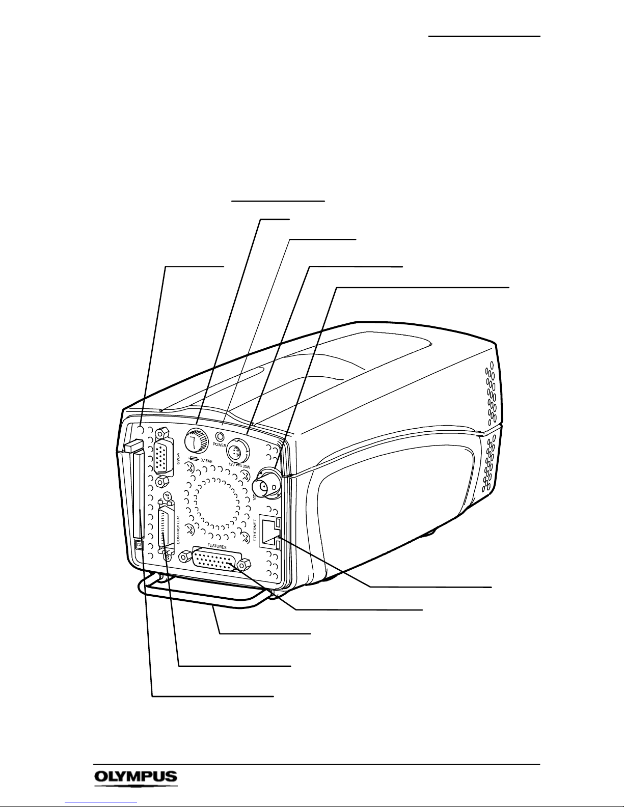
Power connector
Power LED
Fuse
Composite video BNC connector
SVGA connector
Compact flash slot
Controller connector
Protective bar
Ethernet connector
Feature connector
Soft reset
SVGA connector
Page 12

Nomenclature & Functions
10
i--SPEED LT, i--SPEED 2
1. Power Connector
The rear panel Power connector is used to take power into the
camera, nominally 12V DC. This power is used to operate the
camera, but is also used to operate the CDU. The power input
is protected against reverse polarity connection and this will
normally result in a blown fuse.
2. Power LED
The power LED will illuminate when 12V is applied and the fuse
is operating correctly.
3. Fuse
The fuse is replaceable by the user and is accessed by
unscrewing the fuse holder. Care must be taken to replace the
fuse with one of the correct size, type and rating.
4. Composite Video BNC Connector
This connector provides an industry standard PAL or NTSC
composite colour video to a video monitor unit. BNC is an
industry standard connection for this type of signal, and a BNC
composite video cable is provided. The video available from the
connector may be switched between NTSC and PAL via the
menu system in the CDU.
Composite video signals are designed to be driven into a
terminated connector, so care must be taken to ensure that the
last piece of equipment in the BNC cable chain is set to
terminatewith75Ohms.
5. Controller Connector
This connector is used to connect the CDU to the camera. It
carries power from the camera to the CDU, video from the
camera to the CDU and receives button press information from
the CDU.
Although this connector conforms to the LVDS industry
standard, it is recommended that only cables supplied by
Olympus are used and it is imperative that no equipment other
than the CDU is attached to this connector.
Page 13

Nomenclature & Functions
11
i--SPEED LT, i--SPEED 2
6. Ethernet Connector
This connector is a standard RJ45 connector with two integral
LEDs. The signal standard is the Ethernet 10--T or Ethernet
100-- T and the Olympus i -- SPEED LT, i-- SPEED 2 will
automatically switch as appropriate. The Ethernet cable must
be connected to an Ethernet switch, although direct connection
to a PC / laptop is possible if the crossover cable is used. It is
strongly recommended that all the components in the Ethernet
network are compatible with 100--T as this will enable the
camera’s network controller to operate at this higher speed.
7. SVGA Connector
This connector provides a SVGA s ignal which contains the
video image and overlay graphics. When the CDU is being
used, this signal is a copy of the CDU image. The output
standard is the 60Hz SVGA PC video signal and the connector
conforms to the PC video 15 pin D --sub standard. As a result,
this signal may be fed directly to a PC monitor, (CRT or LCD)
and provides the best quality live analogue video signal
available from the camera.
8. Compact Flash Slot
The camera is able to operate with type I and II compact flash
memory card. Once the card is inserted it must be pressed
firmly in place and may be ejected by pressing the button at the
top of the slot. It is not necessary to switch power on and off as
the card is inserted and removed, but care must be taken not to
remove the card while writing, deleting or formatting is in
progress.
9. Feature Connector / Feature Connector Cable
This connector contains a number of signals. They are gathered
together in one connector to reduce the size of the camera’s
back panel and thereby permit the manufacture of the smallest
possible unit. In order to gain access to the signals in this
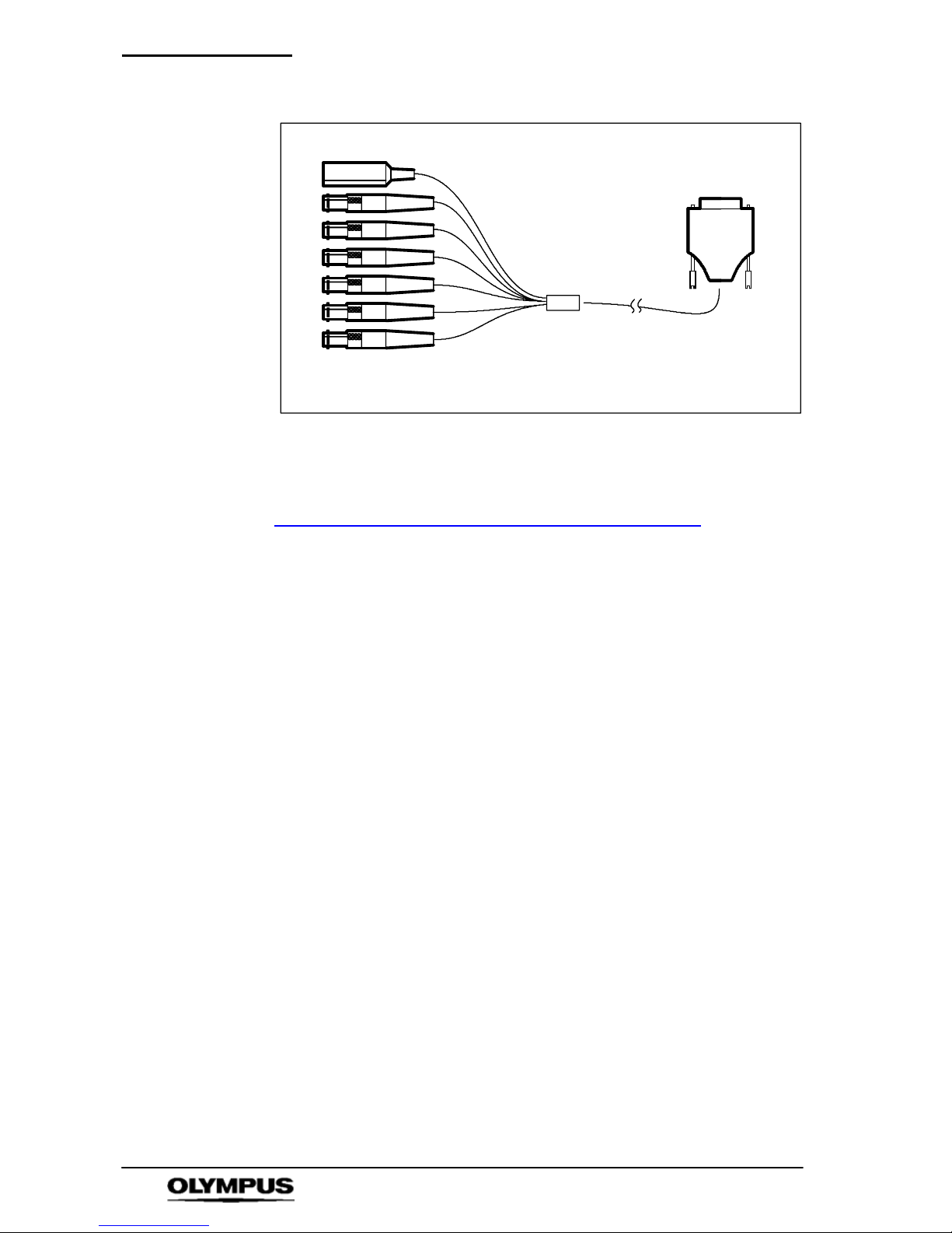
connector, a feature connector cable is supplied and this
terminates in a series of connectors, labelled as follows:
Page 14
Nomenclature & Functions
12
i--SPEED LT, i--SPEED 2
Feature connector cable
Trigger Input / Trigger Switch: This connector (and the
supplied trigger switch if required) are used to trigger the camera
while recording is in progress. Further details are provided in
Chapter 8 “Understanding the Olympus
i--SPEED 2”.
When the trigger is set to 0%, the trigger counter is set to the
length of the memory, so that the trigger point appears at the
beginning (0%) of the final video clip. A setting of 100% will
cause the recording to stop immediately, placing the trigger
event at the end of the video clip.
The signal is TTL level and the user may select rising edge or
falling edge trigger options.
The trigger input contains a “pull-- up” resistor to enable the
supplied trigger switch to be used without further electronics. It
should be noted that the trigger switch provides a falling edge.
In practice, the trigger switch also produces a rising edge
because of switch bounce, but this cannot be guaranteed.
Page 15
Nomenclature & Functions
13
i--SPEED LT, i--SPEED 2
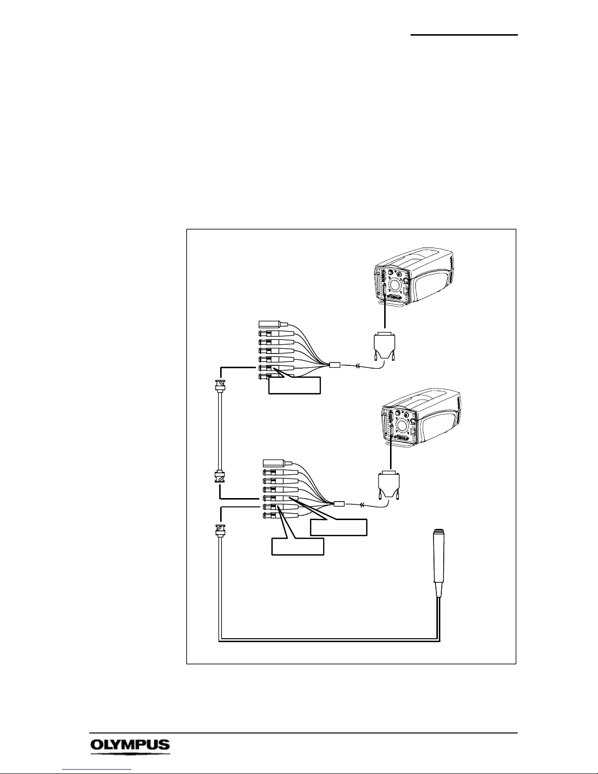
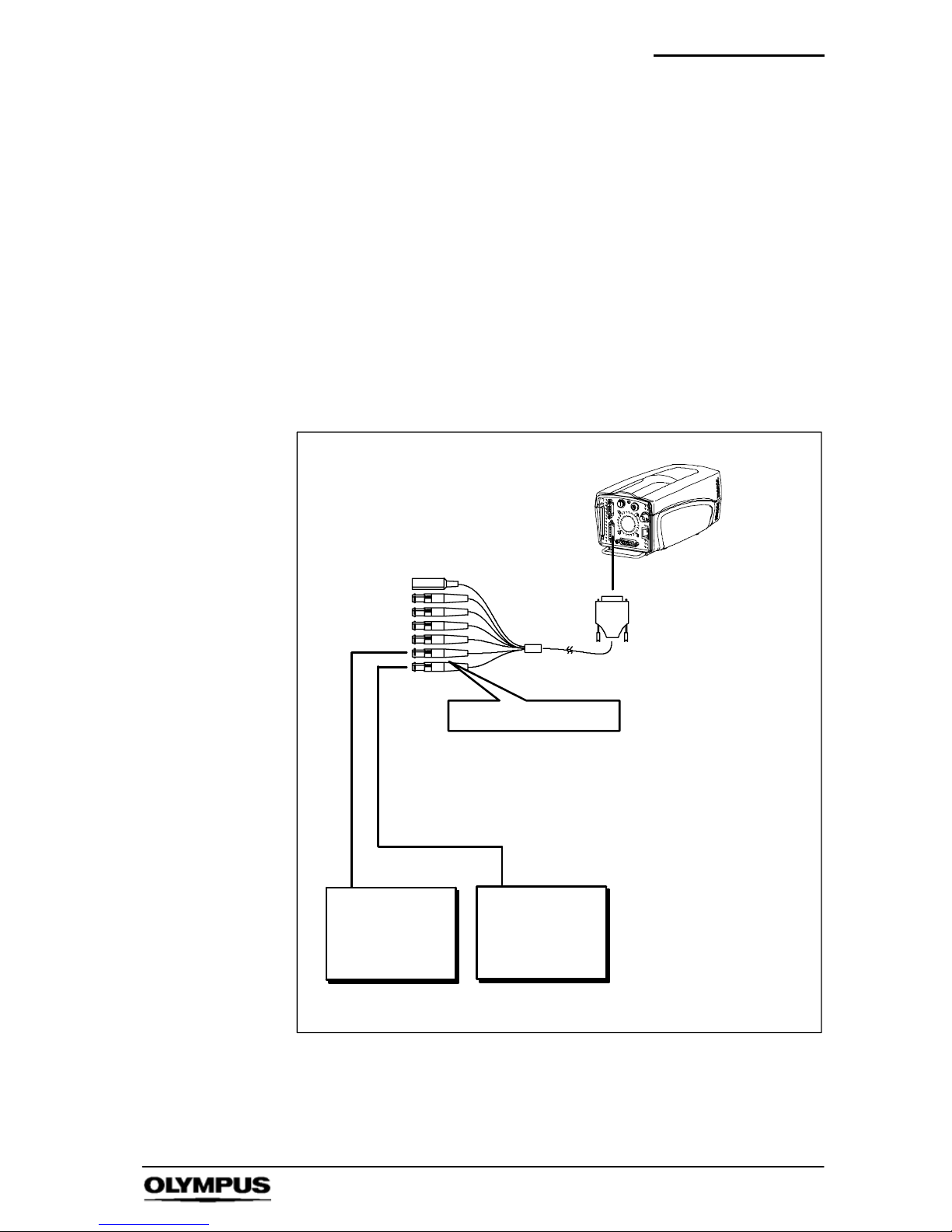
Trigger Output: This output is TTL compatible and gives a 1
microsecond wide active high pulse. The rising edge signifies
the start of the first integration period of the sensor to occur after
recording has stopped. This connector may be used to cause
another camera to trigger after the end of this camera’s
recording. In this way a series of cameras may work in a
daisychain.
When daisy chain operation is used, the first cameras trigger
point may be selected by the user, but it is recommended that
the second camera’s trigger position is set to 0%.
Camera 1
TRIG IN
TRIG OUT
Camera 2
Trigger
switch
BNC (not supplied)
TRIG IN
In addition to all
other connections
Page 16
Nomenclature & Functions
14
i--SPEED LT, i--SPEED 2
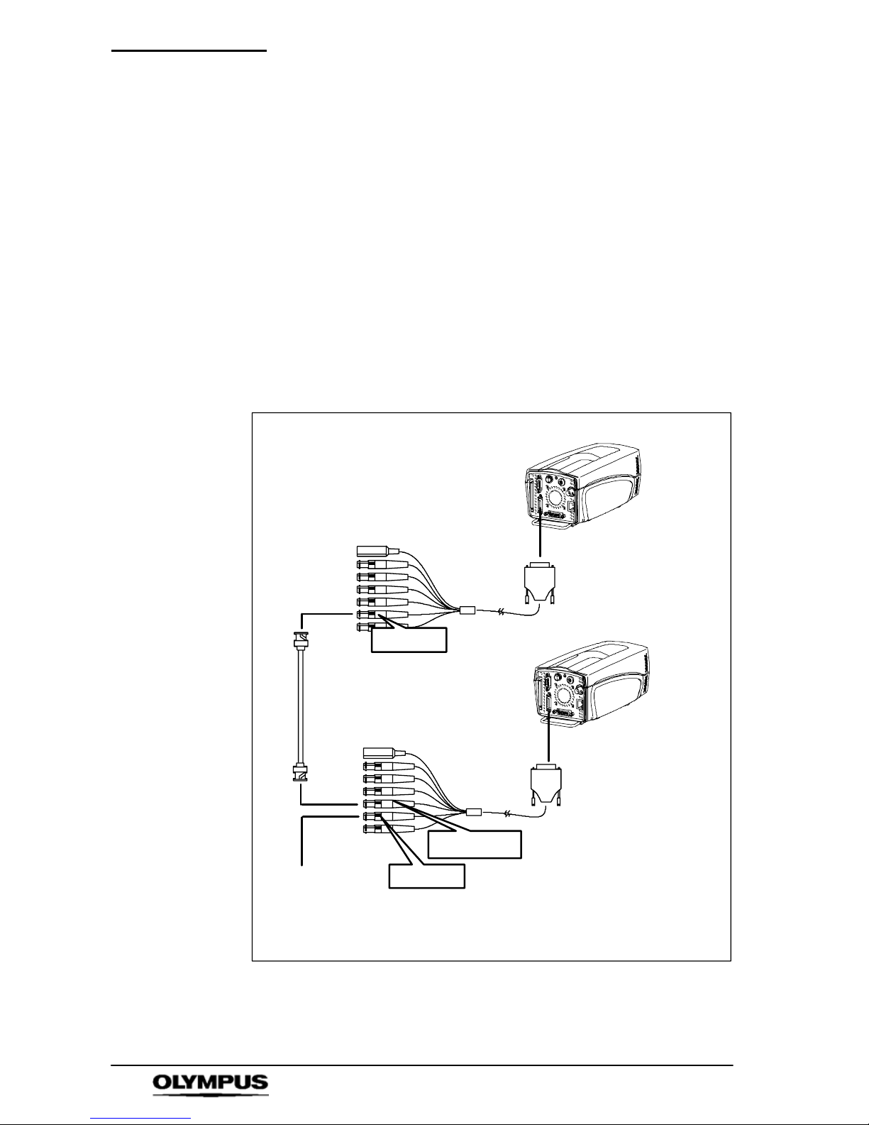
Sync Input: The camera’s frame rate may be determined by an
external signal source, typically another camera. In this case,
the camera would not only lock its frame rate to that of the other
camera, but the exact moment at which each frame is captured
would also be locked to the other camera (+/-- 25ns). In this
way, it is possible to have multiple cameras viewing one event
and taking images simultaneously. The input is TTL compatible
and requires an active high pulse, in which the rising edge
signifies the start of the integration period.
The camera constantly monitors this input and will notify the
user when an incoming sync is detected. When this occurs, the
camera will measure the speed of the incoming signal and offer
the user the opportunity of automatically configuring for
synchronised operation.
Camera 1
SYNC IN
SYNC OUT
SYNC IN
Camera 2
To:
Camera3or
Breakout box (i-- SPEED 2 deluxe software) or
Not used
BNC (not supplied)
In addition to all
other connections
Page 17
Nomenclature & Functions
15
i--SPEED LT, i--SPEED 2
Sync Output: This TTL signal is a 1 microsecond wide active
high pulse in which the rising edge signifies the start of the
integration period. It is used to synchronise other
i--SPEED 2
cameras as mentioned above.
Analogue Input 1 and 2: As well as recording video, the
Olympus i -- SPEED LT, i -- SPEED 2 is able to record two
analogue signals. These are digitised to 8 bits and saved in the
internal memory buffer along with the video. The signals may be
displayed on the CDU or PC screen as required. The signals
are sampled at a speed related to the frame rate and this may
be set from a menu. The sample rate is variable from 1 sample
per frame to 100 per frame, subject to a maximum of 100,000
samples per second.
Camera 1
ANALOGUE IN 1 & 2
BNC cables (not supplied)
User’s
equipment
User’s
equipment
Note: output must be 0 to 5V
In addition to all
other connections
Page 18
Nomenclature & Functions
16
i--SPEED LT, i--SPEED 2
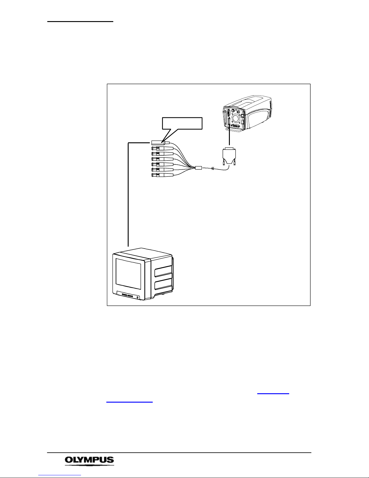
S-- Video Output: This output is a copy of the composite video
(BNC) output, but in the S--Video (sometimes called Y/C) format.
Due to the nature of the S-- Video standard, this signal is slightly
higher quality than the more popular composite video signal.
Camera 1
S--VIDEO
Camera 2
S--video / Y/C cable (4-- pin mini din not supplied)
Video monitor PAL/NTSC (not supplied)
10. Cooling Holes
The rear panel has a number of cooling holes, and more are
located on the sides of the casework at the front of the unit. The
outer holes on the rear panel and the holes at the front of the
unit are air inlets and the holes in a circular pattern on the rear
are air outlets. The primary reason for including forced air
cooling has been to eliminate localised hot spots within the
electronics and care should be taken to ensure that the cooling
holes are kept clear at all times as described in Chapter
9
“Maintenance”
.
11. Soft Reset
This button will allow access to the data recovery menu if the
i-- SPEED LT, i -- SPEED 2 camera stops responding after being
triggered.
Page 19
Nomenclature & Functions
17
i--SPEED LT, i--SPEED 2
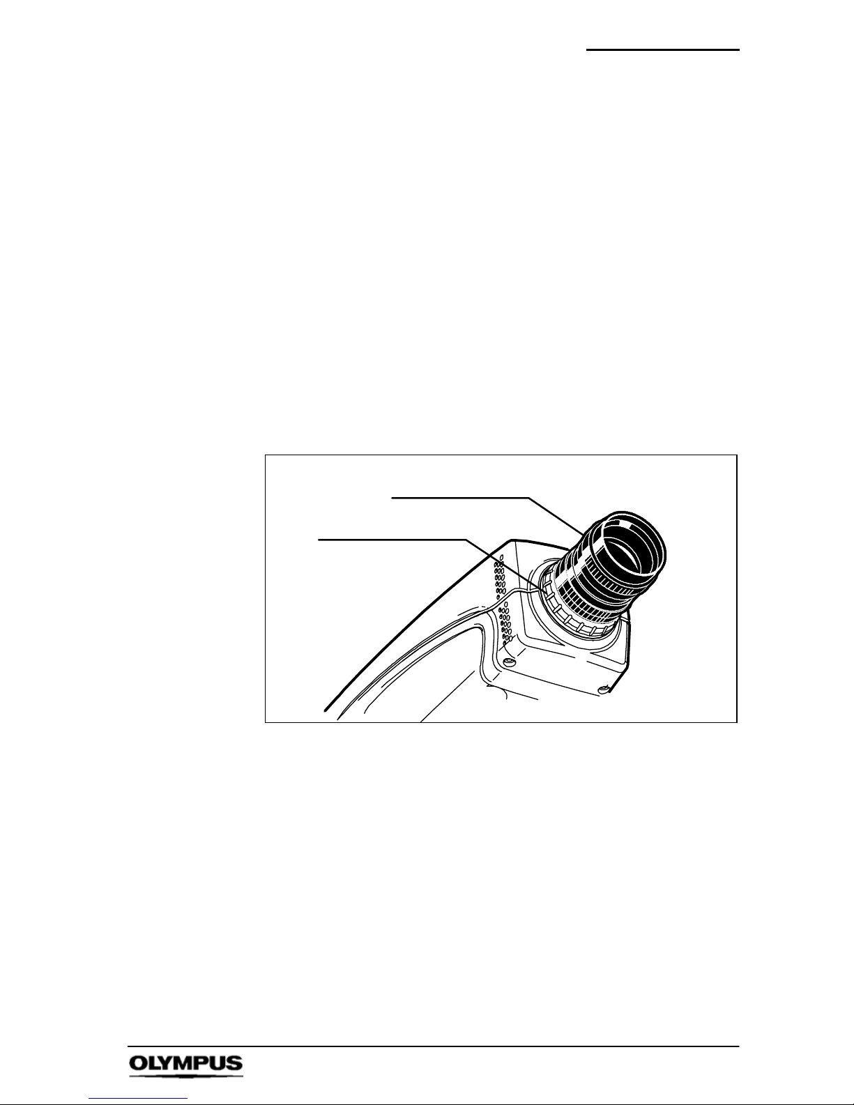
12. Back Focus Control
It is sometimes necessary to adjust the distance between the
C--mount face and the image sensor to accommodate lenses
from different manufacturers and lenses with different optical
tolerances. The Olympus i -- SPEED LT, i -- SPEED 2 has a back
focus assembly located in the front of the unit to permit this
adjustment.
To adjust the back focus, screw a C--mount lens into the
C--mount in the normal way. Turn the locking ring anticlockwise
(when viewed from the front) to unlock the C--mount thread ring
then rotate the lens to adjust the back focus as required -- a
series of ‘click’ positions will be felt. When complete, the
adjustment should be left in one of these ‘click’ positions and the
locking ring rotated clockwise to lock the C-- mount thread ring in
position.
C--mount lens
Locking ring
As a guide, the correct setting of back focus is obtained by
pointing the camera at an object a known distance from the lens,
preferably an “infinite” distance. The scale on the lens is then
used to set the focus ring to this distance. The back focus is
then adjusted to obtain the best image.
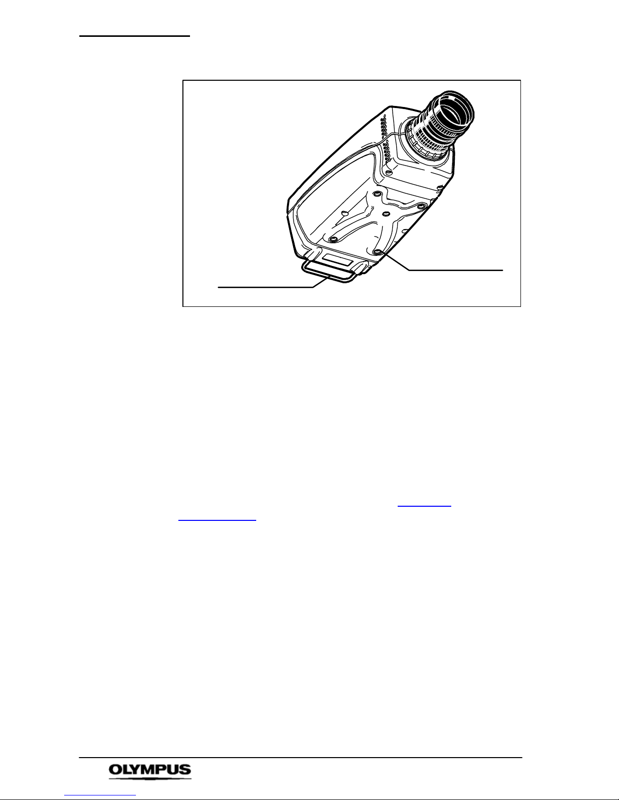
13. Mounting Holes
The base of the unit is fitted with 5 standard ¼” UNC mounting
holes. It is recommended that the central hole is used for
mounting the camera (e.g. to a tripod) and the other holes may
then be used to mount light--weight accessories to the camera.
It is important that the i-- SPEED 2 HG camera is mounted using
the four outer mounting holes when used in high--G applications.
Page 20
Nomenclature & Functions
18
i--SPEED LT, i--SPEED 2
Protective bar
Mounting holes
14. Protective Bar
The back of the unit is fitted with a protective bar. The purpose
of this is to protect the connectors from damage if the unit is
placed on a shelf and pushed back against a wall. In spite of
this, the bar may also be used as a handle to carry the camera
or to support light--weight items when the c amera is mounted on
a tripod.
15. Protective Glass
The image sensor is located at the front of the camera inside the
C--mount aperture. A protective glass is fitted to this aperture to
shield the sensor from dust and damage. It is recommended
that the glass is kept clean as detailed in Chapter
9
“Maintenance”
.
16. Battery Memory
The Olympus i-- SPEED LT, i-- SPEED 2 contains a battery
powered clock and memory. This is used to keep track of the
time and date while the camera is switched off. The memory is
also used to store some of the user controls, such as the TCP/IP
address, the camera’s ID, the TV monitor standard and the
language setting. The battery is a non--replaceable lithium cell
which should last for approximately 10 years. In the event of
battery failure, default values will be used at each switch--on.
Page 21

Nomenclature & Functions
19
i--SPEED LT, i--SPEED 2
3.2 Power Supply/Mains cable
Mains power cable
Power connector
1. ON--OFF switch
The 12VDC Power supply is supplied with the appropriate AC
mains power cable. The power supply unit MUST be earthed
and it is recommended that the mains power cable supplied is
used to maintain standards compliance.
2. Power connector
Connects to the ‘power’ socket of the camera and provides
power to the camera and its controller units
The user must ensure that only the power supply
unit supplied with the Olympus i -- SPEED LT,
i-- SPEED 2 is used and that this unit is only used
to power the camera.
The memory in the camera will be erased if
power is lost.
Page 22
Nomenclature & Functions
20
i--SPEED LT, i--SPEED 2
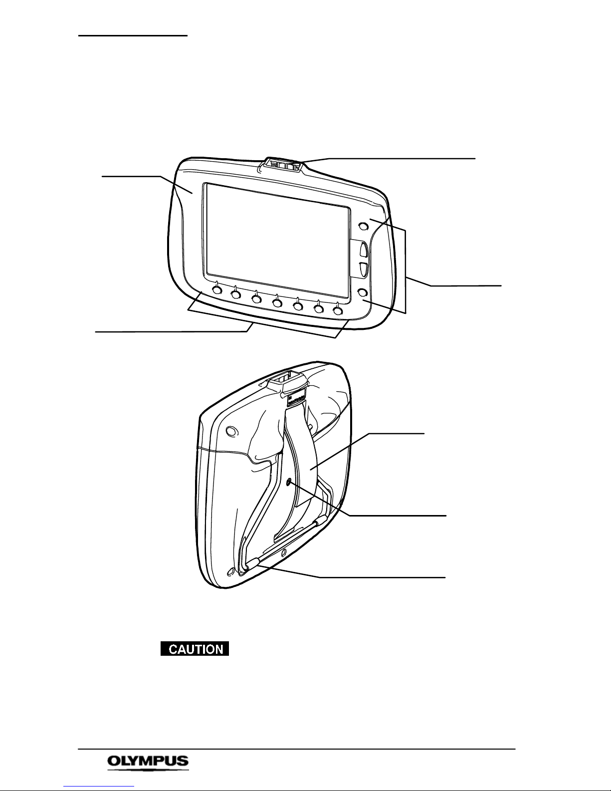
3.3 Controller Display Unit (CDU)
Soft keys
Function keys
CDU
Stand
Tripod mount
Controller cable connector
Strap
The CDU is not high--G rated. The CDU can be
detached and reattached without switching the
camera off.
Page 23

Nomenclature & Functions
21
i--SPEED LT, i--SPEED 2
1. CDU
The CDU displays the image from the camera in realtime and
permits the most flexible use of the camera, by using a series of
buttons around the outside of the screen. The CDU is connected
to the camera’s Controller connector via a 3m controller c able (a
10m cable is available as an optional accessory). The CDU
takes power and video from the camera and requires no
batteries or further connections.
The camera is able to recognise the presence of the CDU and
operates a specialised menu system. When changing from
CDU and viceversa, the power should be switched OFF and ON
again.
LCD Panel, Viewing Angle: At the time of design and writing
this manual, the LCD panel used in the CDU is the best
available LCD panel of this size and resolution. Even this
market leading panel, however, has a restricted viewing angle in
the vertical direction and the user is advised to experiment with
the CDU to find the optimum angle at which to view the image.
Protective Screen: Although the CDU LCD screen is protected
by a tough plastic sheet, it is still recommended that care is
exercised when handling this unit. It is also important to keep
this screen clean to preserve its anti--glare properties and this is
detailed in Chapter 9 “Maintenance”
.
2. Soft keys
The bottom seven buttons on the CDU are used as “soft keys”,
that is the function of each button is dependent on the text
written above to it on the screen.
3. Function keys
The four buttons on the right hand side of the CDU are
dedicated function buttons, these are Text, Back, Up and Down.
The menu system has been specially constructed to take
maximum advantage of this layout.
4. Stand
The CDU is equipped with a stand which may be set to a
number of ‘click--stop’ positions to allow standing on a flat
surface at various angles or hanging from a convenient hook.
The stand may also be folded flat for storage or when the strap
is used.
Page 24

Nomenclature & Functions
22
i--SPEED LT, i--SPEED 2
5. Strap
The back of CDU has an adjustable strap which may be used to
allow the unit to be conveniently held with a single hand.
6. Tripod Mount
The CDU contains a tripod mounting hole with the industry
standard thread and is located under the strap.
The CDU must not be connected to any
equipment other than the Olympus i-- SPEED LT,
i-- SPEED 2 camera, otherwise equipment
damage will occur.
NOTE
To maintain standards compliance, it is
recommended that only cables supplied by
Olympus are used.
Page 25
System Connection
23
i--SPEED LT, i--SPEED 2
Chapter 4 System Connection
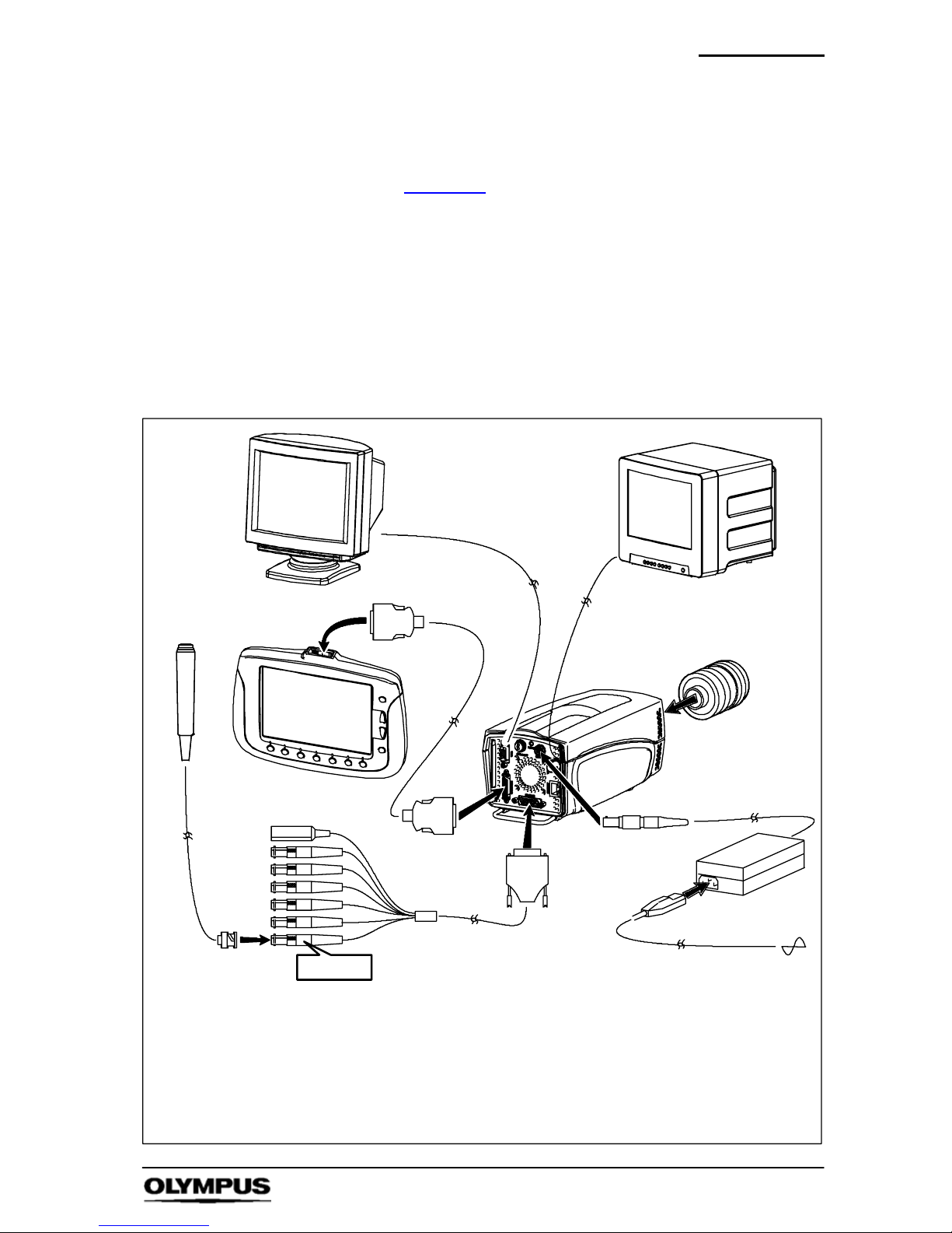
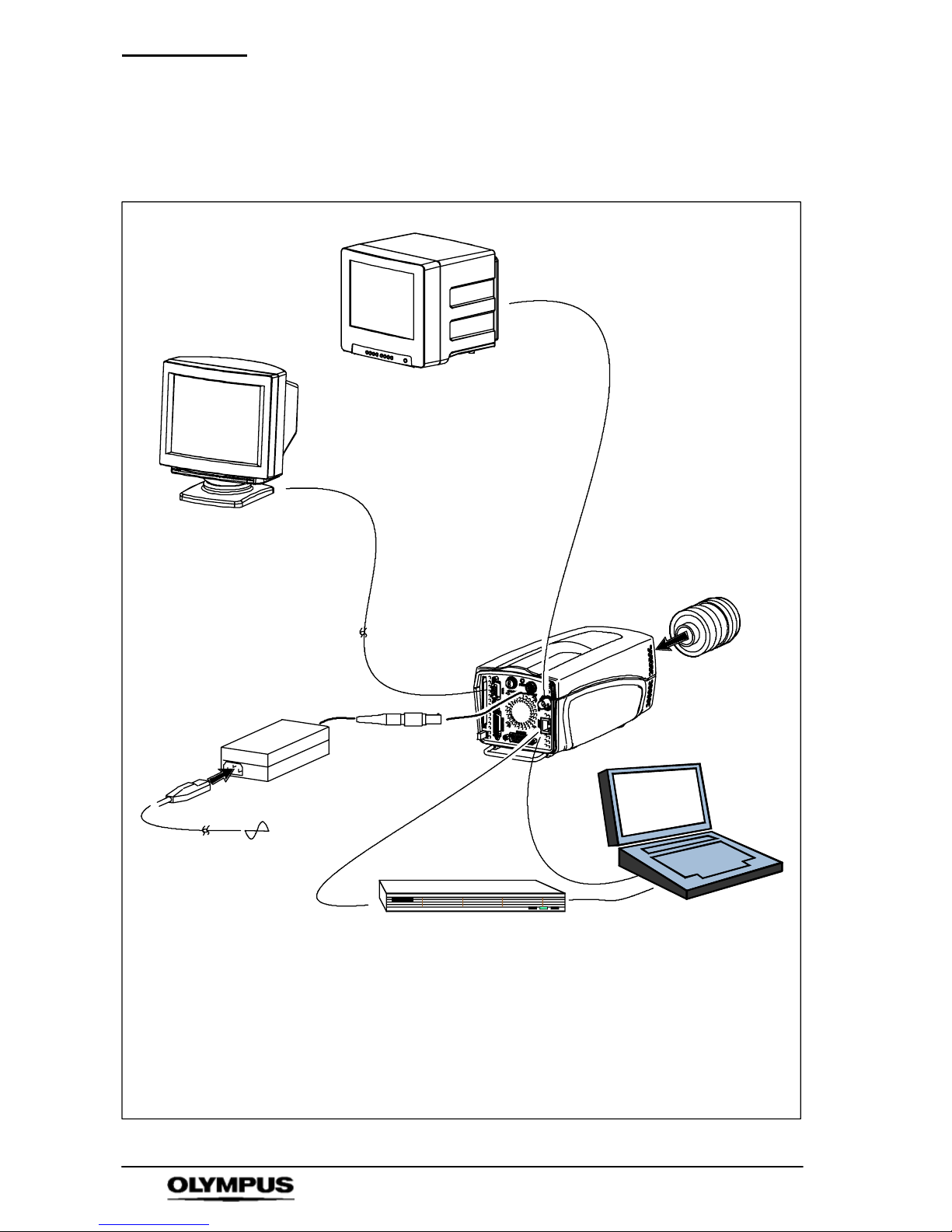
As described in Chapter 1,thei-SPEED 2 c amera system can be
configured in two ways using a Controller Display Unit (CDU) or
Ethernet via connection to a PC or Laptop. The i-SPEED LT
camera system may only be configured using a Controller Display
Unit (CDU)
.
Refer to the connection diagrams shown below and connect the
system as appropriate.
4.1 Controller Display Unit (CDU)
Key
1 Trigger switch 6 Power supply unit (PSU)
2 CDU (Controller Display Unit) 7 Mains power cable
3 Controller cable 8 C--Mount lens
4 Camera 9 VGA cable
5 Feature connector cable 10 Composite video BNC cable
1
2
3
4
5
6
7
8
3
TRIG IN
*not all items shown are supplied in the standard set, see Chapter 2.
9
10
Optional
PC/TV monitor
Page 26
System Connection
24
i--SPEED LT, i--SPEED 2
4.2 PC/Laptop connection
Key
1 Camera 6 Laptop (or PC)*
2 Ethernet cable (black) 7 Network switch *
3 C--Mount lens * 8 VGA cable *
4 Power supply unit (PSU) 9 Composite video BNC cable
5 Mains power cable 10 Ethernet crossover cable (grey)
1
2
5
4
8*
3*
6*
* not supplied
7*
9
Optional
PC/TV monitor
10
Page 27

Getting Started
25
i--SPEED LT, i--SPEED 2
Chapter 5 Getting Started
This section provides a functional description followed by the basic steps
required to start using the i-- SPEED LT, i-- SPEED 2 camera system.
5.1 Functional Description
Assuming the system has been connected as described in Chapter 4,the
typical sequence of events is as follows:
The frame speed and shutter settings are c hosen, the lighting and lens are
adjusted appropriately and the camera is placed in record mode.
The camera then takes video at high frame rates and stores it in the
built--in memory. This memory is configured in a circle so that, once the
memory is full, each new frame replaces the oldest stored frame. In this
way, the camera keeps a rolling history of the scene it views and this
process can continue indefinitely. Once the desired event has occurred,
the camera is stopped or triggered.
During the entire set--up and record process, the CDU and any monitor
attached will display the live image in full colour and in real time.
Once the required video clip is stored in memory, it may be viewed by
using the player function. In this mode, video may be played forwards or
backwards at a range of speeds. A convenient bookmark system is
provided (CDU only) for easy navigation between sections of interest.
The memory in the camera will be erased without power, so if it is
necessary to preserve the captured video after power off, it may be
recorded onto a compact flash memory card, which is inserted into the
card slot provided. The internal memory is much bigger than any card
currently available, so only a subsection of video may be stored. High
speed video clips generally contain a large amount of “dead time” and a
relatively small amount of useful motion, in recognition of this, the Olympus
i-- SPEED LT, i -- SPEED 2 has a clip select function which allows a precise
choice of the video to be saved.
Further to these functions, it is sometimes necessary to measure a feature
of the recorded motion and the Olympus i-- SPEED 2 contains an
advanced measurement suite.
Page 28
Getting Started
26
i--SPEED LT, i--SPEED 2
5.2 Use with the CDU
This section describes the basic steps required to start using the
i-- SPEED LT, i -- SPEED 2 camera system with the CDU. Additional
information regarding functionality of the CDU can be found in Chapter 6
.
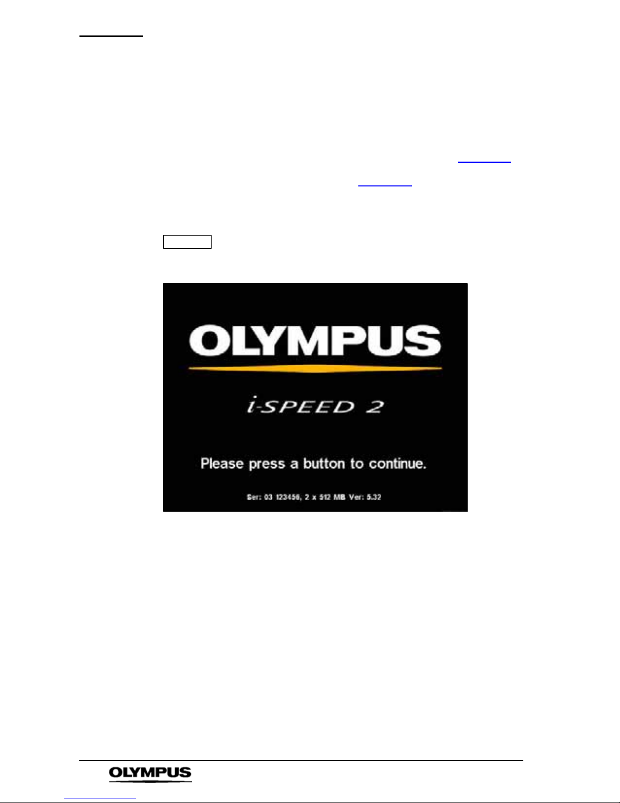
1. Connect the system as described in Chapter 4, then connect the
mains power cable to a suitable AC wall outlet and switch the
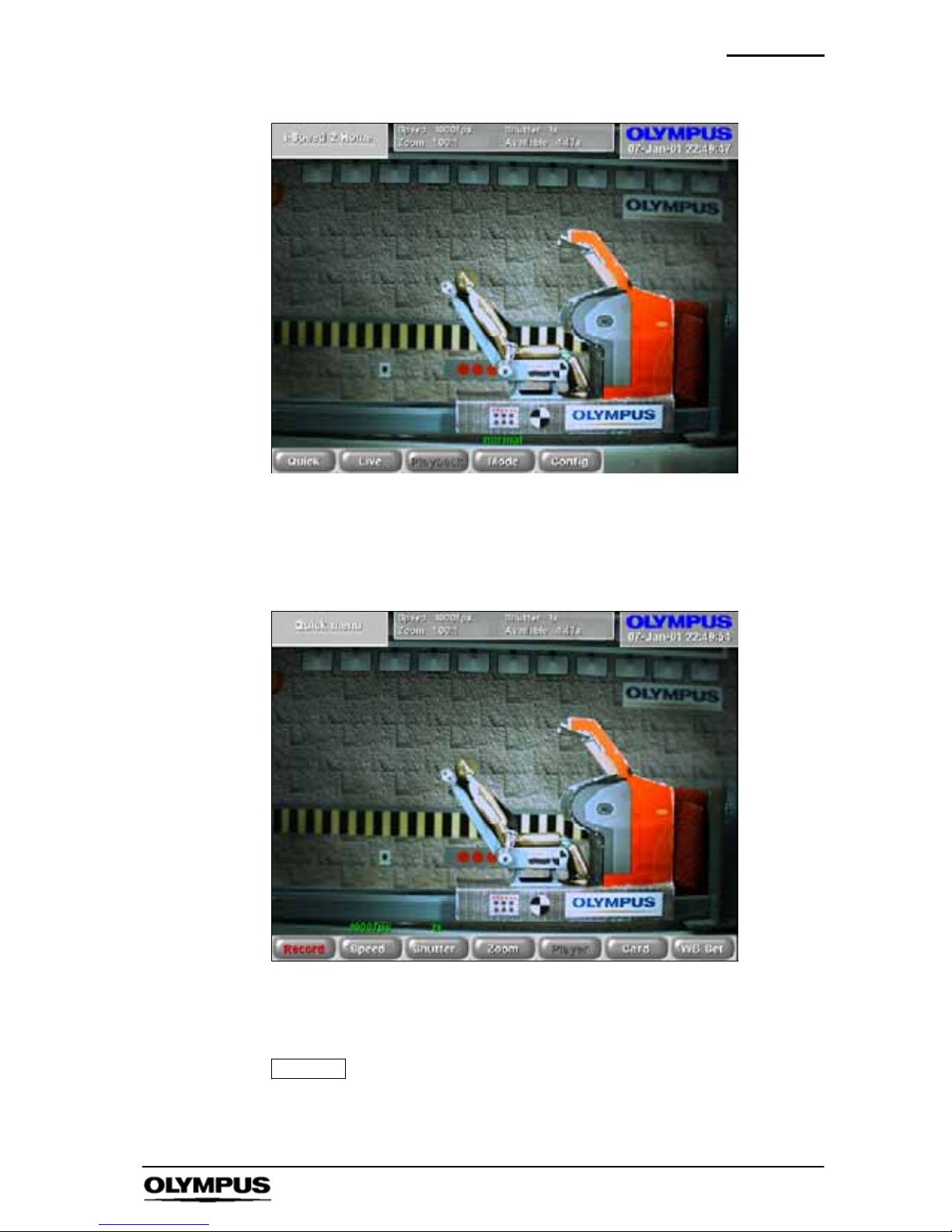
power ON -- the i-- SPEED 2 splash screen is displayed on the CDU.
NOTE
When using the i-- SPEED 2 HG, the lens must be
completely covered (eg with a lens cap) from power on
until the splash screen appears.
2. Press any key, a live video image is displayed on the CDU. Adjust
the lens focus and iris as required to achieve a sharp, bright image.
Page 29
Getting Started
27
i--SPEED LT, i--SPEED 2
3. Depress the Quick button to enter the Quick menu
4. Depress the Speed and Shutter buttons to select the desired frame
speed (def: 60fps) and shutter speed (def: x1). You may need to
re--adjust the lens focus and iris to achieve a sharp, bright image.
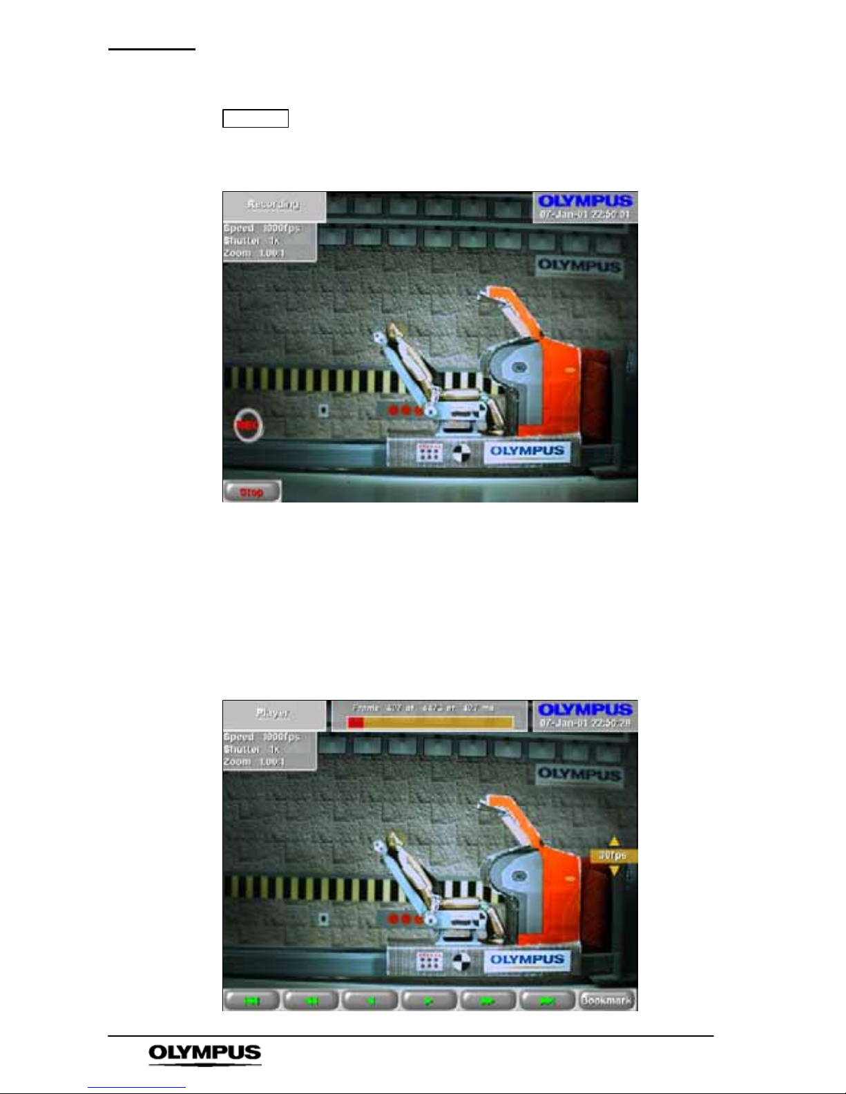
5. Depress the Record button, a camera icon is displayed and the
camera records video into its circular buffer until the Stop button is
depressed or the trigger button is pressed.
NOTE
If the trigger is used, recording will stop after a delay.
This delay depends on memory size, the trigger position
setting and frame speed.
Page 30
Getting Started
28
i--SPEED LT, i--SPEED 2
NOTE
When using the i-- SPEED 2 HG for high--G tests,
disconnect the CDU from the camera. When recording
has stopped, reconnect the CDU.
When recording has stopped, whether by trigger or STOP button,
the camera will present the Playback Menu. Press the Player
button to enter Player menu and display the first recorded image in
the memory.
6. Player controls are: jump back, rewind, play backwards, play
forwards, wind forwards, jump forward (to bookmark). Each button
when pressed changes to a Stop button
Page 31
Getting Started
29
i--SPEED LT, i--SPEED 2
The Bookmark control is used to set bookmarks at points of interest
and are displayed as white vertical lines in the progress bar at the
top of the screen. When the Trigger is used, an automatic
bookmark is displayed as a Red vertical line.
7. Use the up/down buttons on the right hand side of the CDU to
adjust playback speed.
8. If the v ideo clip is to be saved, insert a compact flash memory card
into the compact flash slot in the camera.
9. Depress Back to return to Playback menu and press Clip select.
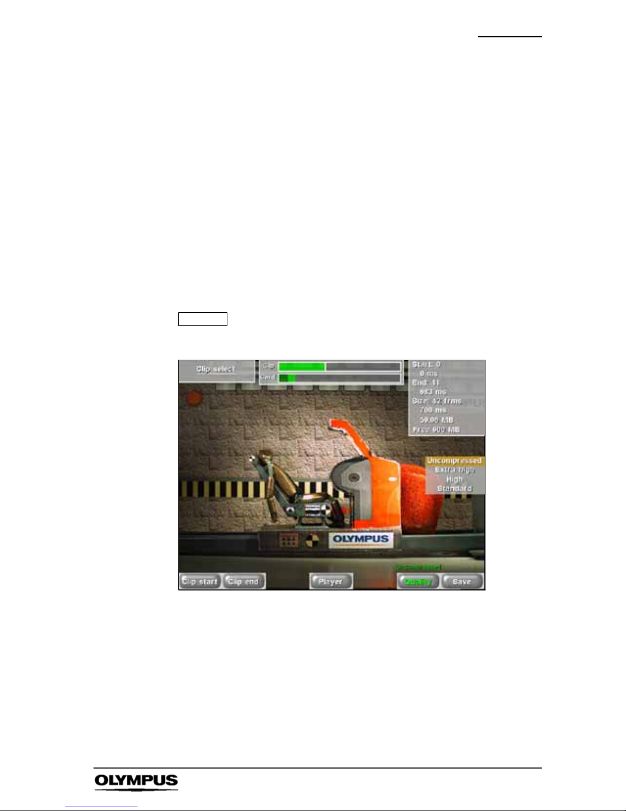
Use the control buttons to move to the start frame and press Clip
start, move to end frame and press Clip end.
Frame and memory status is displayed top right.
NOTE
Note that Clip select will not be available until a card is
inserted.
10. Depress Save.
11. Depress BACK as required to return to the Home menu.
5.3 Use with a PC/Laptop
For detailed use with a PC/Laptop, refer to the instruction manual provided
with the software. The i--SPEED 2 is supplied with a factory set IP address
of 192.168.0.54. The user may change this address.
Page 32

Software reference (CDU) i--SPEED LT
30
i--SPEED LT, i--SPEED 2
Chapter 6 Embedded Software
Reference (CDU)
i- SPEED LT
Introduction
This reference section describes the camera’s embedded software
and its user interface from the viewpoint of the CDU. In this
section, items which are printed like this
signify the name of a sub
menu, controls are described whenever they appear in a menu.
Operation of the CDU menus
To navigate through the menu system, the button nearest the
desired selection is pressed.
When a control is selected, the desired value may be chosen by
using the
Y and B buttons on the right hand side of the screen.
Repeatedly pressing or to press and hold the control button will
cycle through the available values. The current value is displayed
above the control button and also next to the
YBbuttons.
To return to a higher menu, the Back button is pressed. If there is a
requirement for a text free screen, the Text button is used to cycle
the on--screen text through full, time/date only and off options.
Page 33
Software reference (CDU) i--SPEED LT
31
i--SPEED LT, i--SPEED 2
6.1 Menu Screens
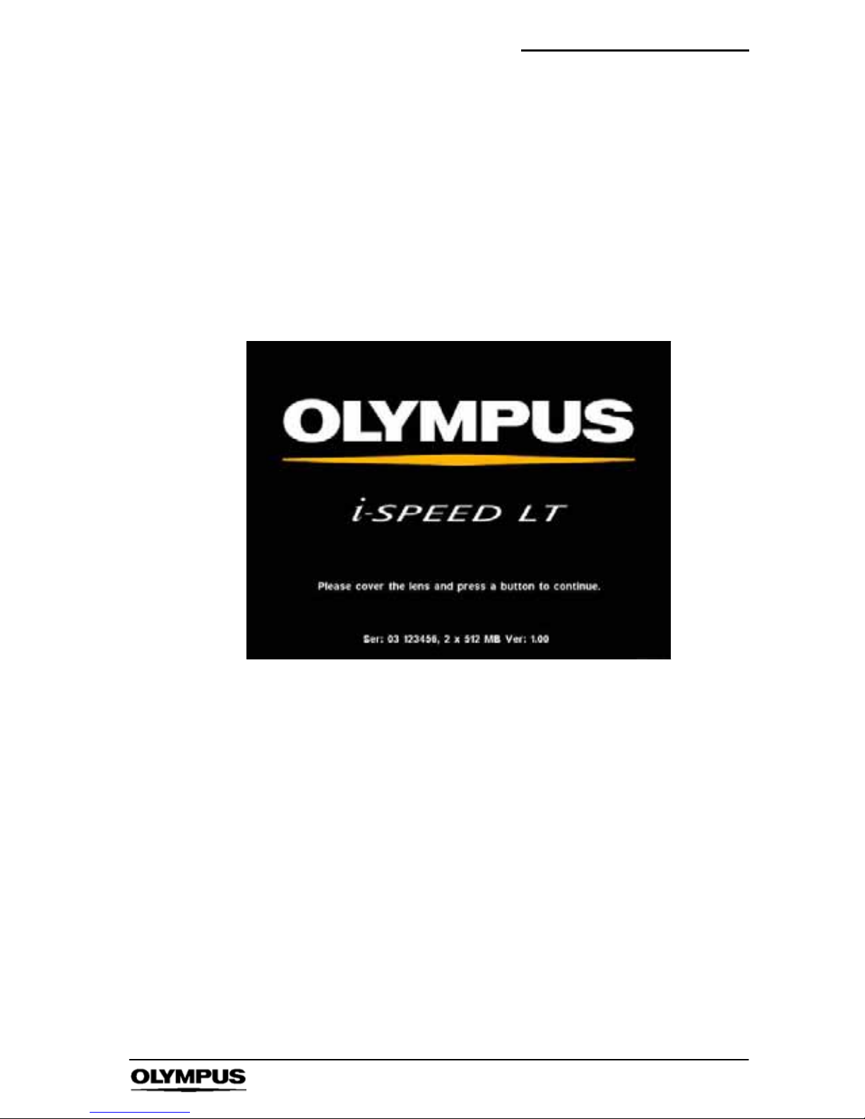
1. OLYMPUS i-- SPEED LTSplash Screen
This screen is displayed while the camera starts up and configures
the internal software. It contains data on the memory configuration
of the camera, the serial number and the software v ersion number.
To exit this screen (and to perform an initial calibration of the
sensor), the user should press a button on CDU while covering the
camera lens.
Page 34
Software reference (CDU) i--SPEED LT
32
i--SPEED LT, i--SPEED 2
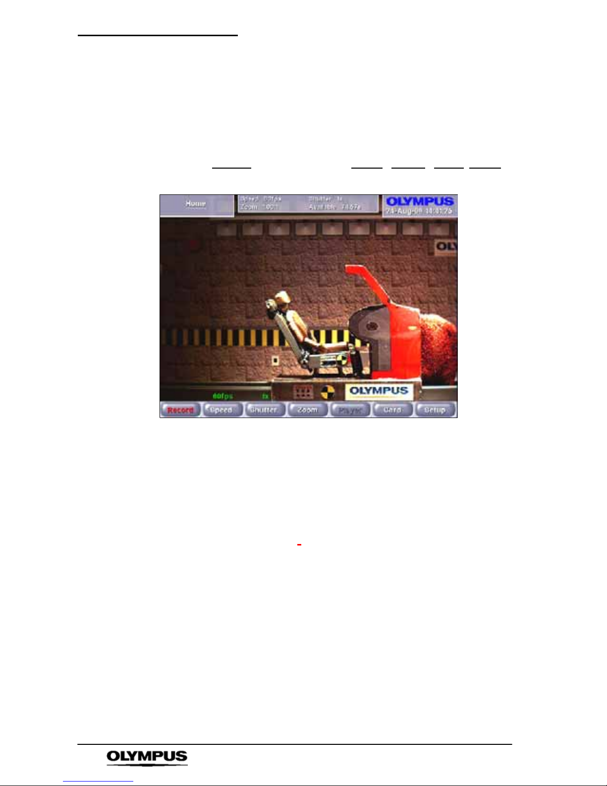
2. i-- SPEED LT Home Menu
This is the top level or home screen of the menu system. It may be
accessed by pressing the Back button repeatedly from any position
in the menu system.
Options: Record
Speed Shutter Zoom Player Card Setup
S The CDU will display a live image
` Speed Control
This control allows the user to set the frame speed of the camera.
The lowest speed available is 60 frames per second as this is
almost equal to the SVGA display specification. The maximum
speed is limited to 2000fps.
As described in Chapter 8,
the user will normally need to open the
iris of the lens and/or add more light as the speed is increased.
Further, the image will appear to zoom in as the frame speed is
increased above 1,000 frames per second.
` Shutter Control
It is sometimes desirable to reduce the time during which the
sensor gathers light (called “exposure time”, “integration time” or
“shutter time”) in order to reduce motion blur and “freeze” the
motion in each frame. The default shutter time is equal to the frame
time, but this may be reduced by this control. The shutter time is
measured as the ratio between frame time and shutter time, e.g.
x10 means that the shutter is open for 1/10 of the frame period. The
shutter period may range from the frame period (x1) to 1/200 of the
Page 35

Software reference (CDU) i--SPEED LT
33
i--SPEED LT, i--SPEED 2
frame period (x200), but is subject toa5microsecondlowerlimit
anda1secondupper limit.
The user should note that as the s hutter ratio is increased, the
camera will require more light.
Page 36
Software reference (CDU) i--SPEED LT
34
i--SPEED LT, i--SPEED 2
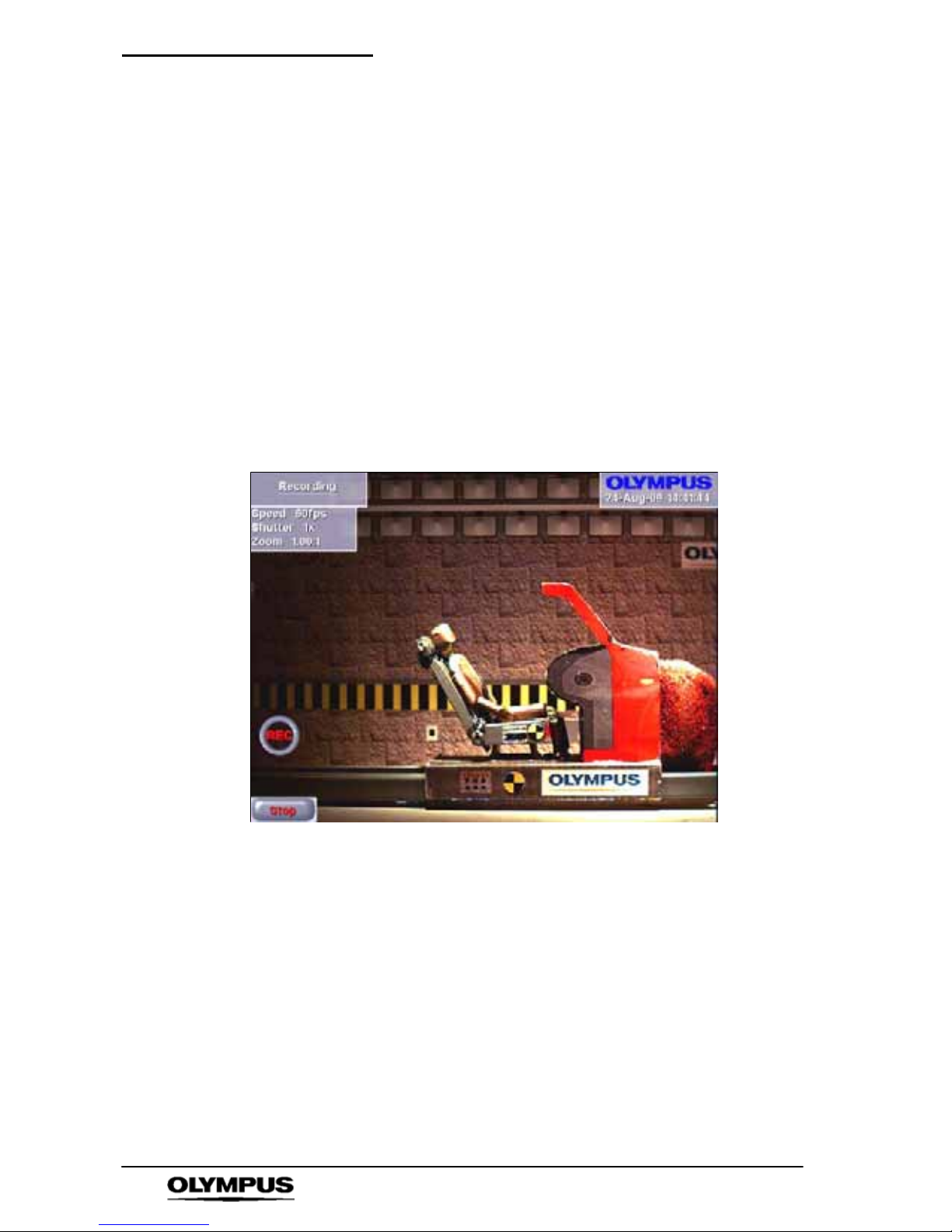
3. Recording Menu
When this menu is displayed, the Olympus i-- SPEED LT is
recording video into its circular buffer . The record action is
confirmed by the presence of an icon displaying “REC” in red.
When a trigger signal is received and the camera is working
through the length of its trigger counter, the animation is changed to
read ‘TRIG
’ in green.
When recording has stopped, whether by the trigger or the STOP
control, the camera will automatically present the Player Menu and
thereby display the first recorded image in the memory.
Access: i-- SPEED LT Home
' Record
Options:STOP
S The CDU will display the live image
` STOP Control
This control will cause the camera to stop recording immediately,
regardless of the setting of the trigger position.
Page 37
Software reference (CDU) i--SPEED LT
35
i--SPEED LT, i--SPEED 2
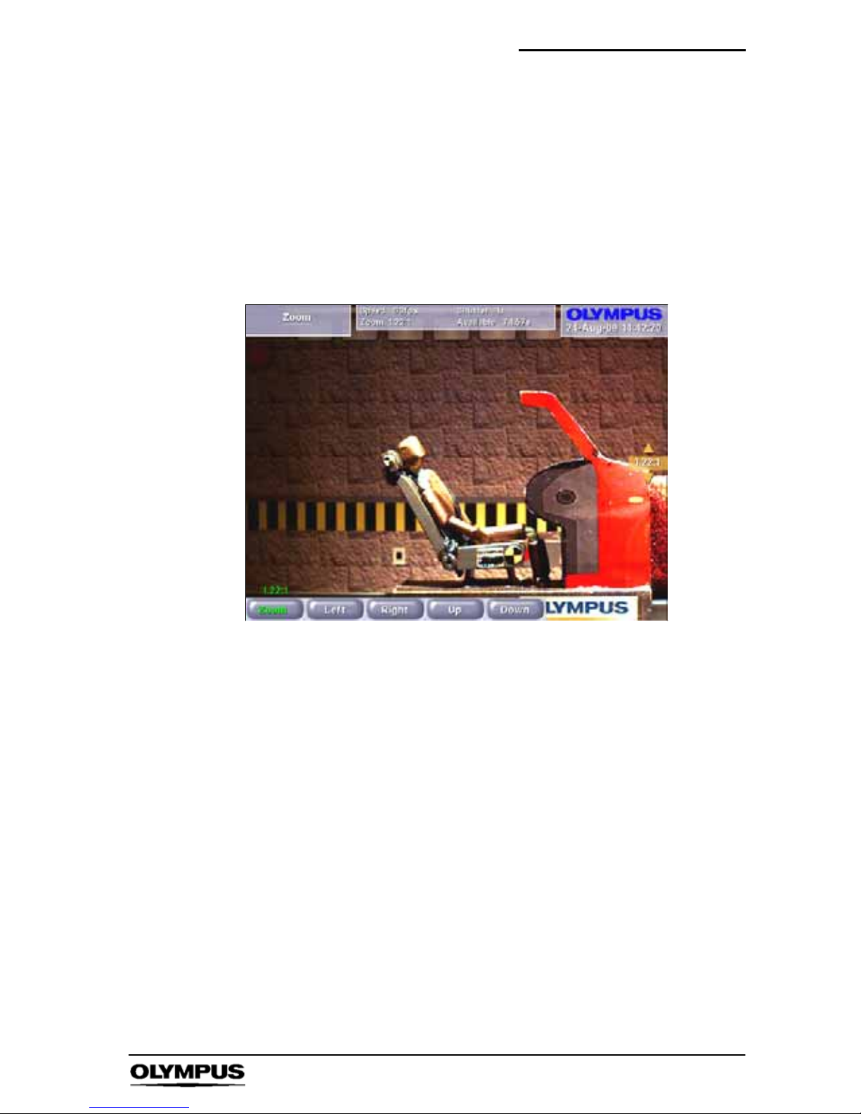
4. Zoom Menu
This menu provides access to the controls of the built--in zoom
engine.
Access: i-- SPEED LT Home
' Zoom
i-- SPEED LT Home
' Player ' Zoom
Options: Zoom Pan Left Pan Right Pan Up Pan Down
S The CDU will display the live or playback image
depending on the route taken to activate the menu
` Zoom Control
The Olympus i-- SPEED LT camera has a built--in zoom engine
which can electronically magnify the video image by up to 10 times.
The user may adjust the level of zoom using the zoom control in
this menu.
It should be noted that the z oom engine is automatically operated
when high frame rates result in the active area of the sensor being
reduced or when the “square” economy mode is selected. In these
circumstances, the user may still zoom further into the zoomed
image, but the 10 times limit is applied to the total zoom employed.
` Pan Control
For the convenience of the user, pan controls are also provided.
These are individually disabled when the limit of the pan in a given
direction is reached, and all are disabled when the zoom engine is
turned off (1:1).
Page 38
Software reference (CDU) i--SPEED LT
36
i--SPEED LT, i--SPEED 2
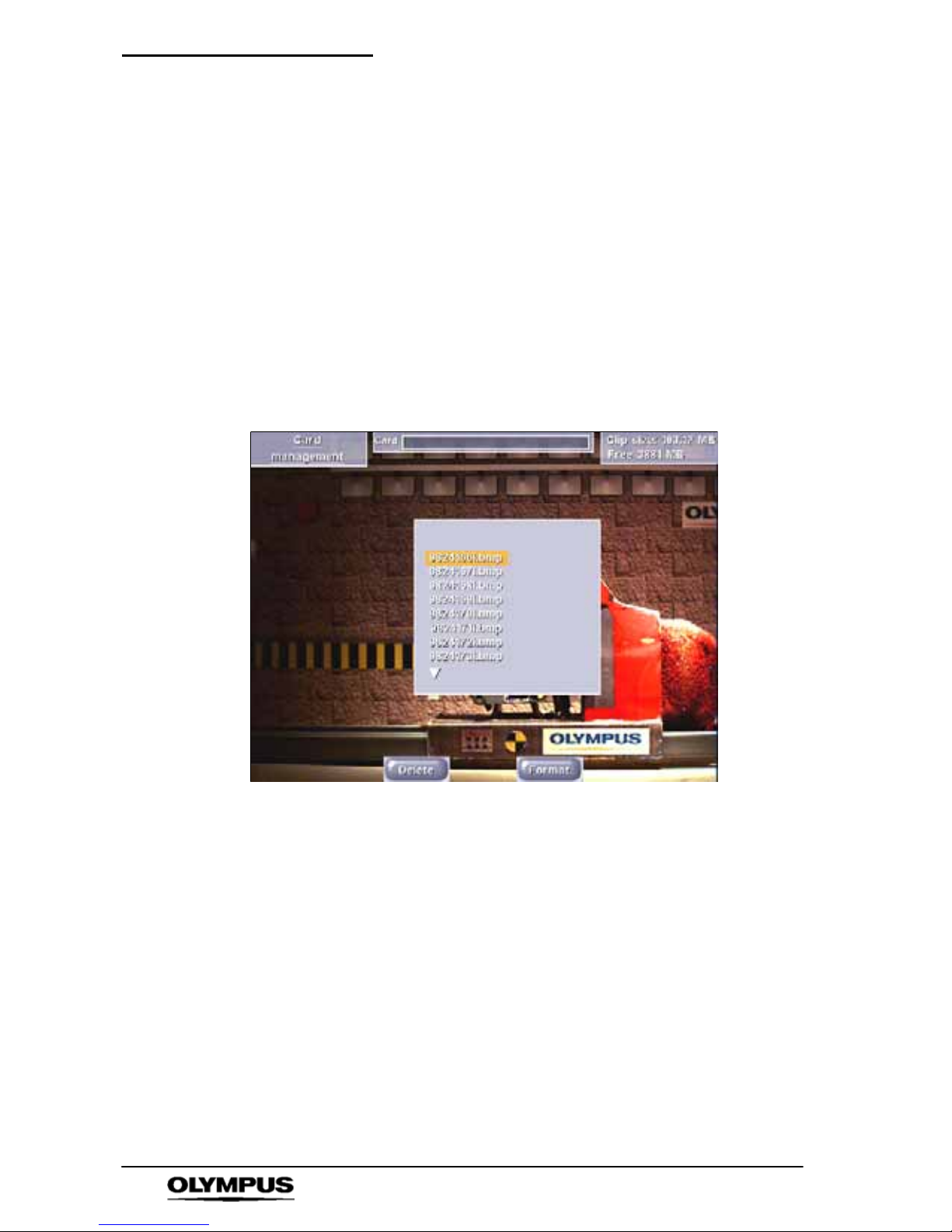
5. Card Management Menu
This menu makes available the items which relate to the
management of the removable compact flash memory card.
The screen includes a list of the files on the card and one of these
will be highlighted by a selection bar.
Automatically appears after saving a file
Access: i-- SPEED LT Home
' Card
Options: Delete Format
The CDU will display the splash screen logo and card directory.
` Delete Control
This control is used to delete the selected file from the card. The
user is protected from error by a confirmation question.
` Format Control
The user is able to format the card. This will delete all the data on
the card and also prepare a new card for its first use. The user is
protected from error by a confirmation question.
Page 39
Software reference (CDU) i--SPEED LT
37
i--SPEED LT, i--SPEED 2
6. Setup Menu
This menu makes available all the items which relate to the live
view systems of the camera. It would be of benefit to read Chapter
8 “Understanding the Olympus i -- SPEED LT” for further
descriptions on several of the terms and phrases used in this
section.
Access: i-- SPEED LT Home
' Setup
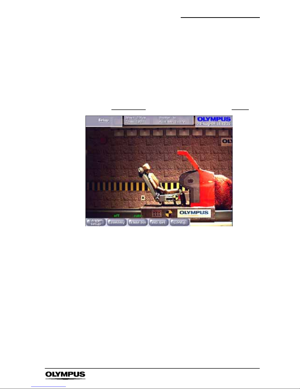
Options: Trigger setup
Economy White Bal WB Set Config
S The CDU will display the live image
` Economy Control
It will be noted that many high speed events are primarily horizontal
or vertical in nature and so the edges of the screen often contain no
useful video information. It is also sometimes desired to have a
longer record time than that given by the available memory option.
This control addresses both of these issues by causing the camera
to use a central subsection of the sensor, rather than the maximum
available area. This has the effect of reducing the number of pixels
recorded in each frame and so effectively increasing the record
time available.
Where possible, the zoom engine will return the image to full
screen.
Page 40

Software reference (CDU) i--SPEED LT
38
i--SPEED LT, i--SPEED 2
` White Bal Control
The Olympus i-- SPEED LT provides two types of white balance,
pre--set and automatic. Several pre--set white balance settings are
provided, based on light source technologies found in the Olympus
range of industrial light sources.
The automatic function relies on the user placing a pure white
reference (sheet of paper etc.) if front of the camera, completely
filling the field of view and then pressing the WB Set button. This
paper must not be removed until the white balance is complete. An
on screen message shows the status of the white balance process.
The balance achieved is remembered by the camera while
switched off.
NOTE
This control is not available in monochrome cameras.
` WB Set Control
This control activates the automatic white balance function. Before
pressing this control, the user must place a pure white reference
(sheet of paper etc.) if front of the camera, completely filling the field
of view. This must not be removed until the white balance is
complete. An on screen message shows the status of the white
balance process.
Please refer to Chapter 8 “Understanding the Olympus i--SPEED
2”
for a further description.
NOTE
The control is only available if the white balance mode
is set to automatic.
Once set, the white balance values will be stored in
non-- volatile memory. Thus if camera power is removed,
the camera will return to the user set white balance
values.
Page 41
Software reference (CDU) i--SPEED LT
39
i--SPEED LT, i--SPEED 2
7. Config Menu
This menu makes available all the items which relate to the
configuration of the camera.
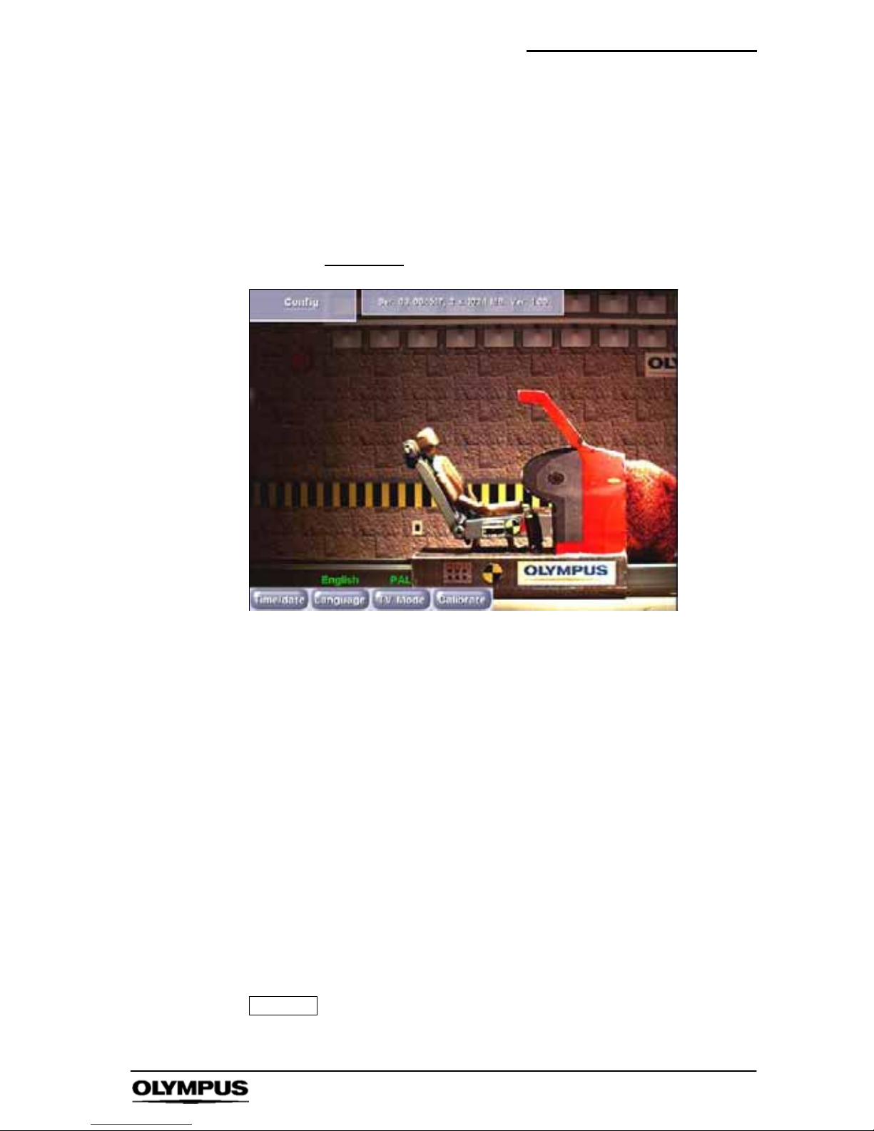
Access: i-- SPEED LT Home
' Setup ' Config
Options: Time/Date
Language TV Mode Calibrate
` Language Control
This control permits the user to set the language in which the
menus are displayed. The language of the information tiles and
control value display is not changed.
` TV Monitor Control
The composite video output connector (BNC) is able to provides
either NTSC or PAL and this selection is made by this control.
` Calibrate Sensor Control
In common with all CMOS sensor chips, the Olympus i-- SPEED LT
sensor requires a calibration system to remove fixed pattern noise.
This control allows the user to manually trigger the calibration
system. Further discussion may be found in Chapter 8 ”
Understanding the Olympus i-- SPEED 2’’.
NOTE
To successfully calibrate the sensor, the user must
cover the lens.
Page 42
Software reference (CDU) i--SPEED LT
40
i--SPEED LT, i--SPEED 2
8. Time / Date Setting Menu
This menu permits the setting of the time and date of the on-- board
clock of the camera.
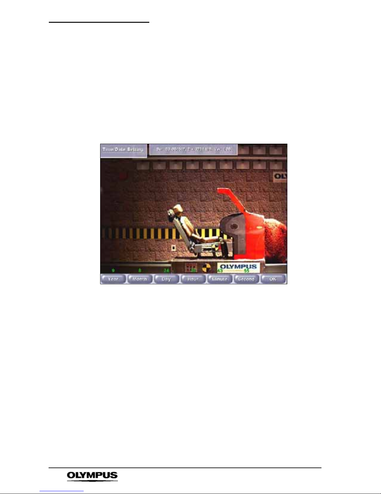
When the appropriate time and date have been set, the OK button
should be pressed.
Access: i-- SPEED LT Home
' Setup ' Config ' Time/Date
Options: Year Month Day Hour Minute Second OK
S The CDU will display the splash screen logo
` OK Control
This control confirms the numerical entry just made and also
returns to the previous menu.
Page 43
Software reference (CDU) i--SPEED LT
41
i--SPEED LT, i--SPEED 2
9. Trigger Setup Menu
This menu makes available all the items which relate to the live
view systems of the camera. It would be of benefit to read Chapter
8 “Understanding the Olympus i -- SPEED LT” for further
descriptions on several of the terms and phrases used in this
section.
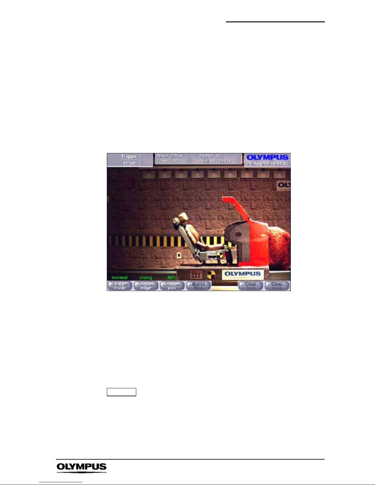
Access: i-- SPEED LT Home
' Setup ' Trigger Setup
Options: Trigger mode Trigger edge Trigger pos Burst time
Clear last Clear mem
S The CDU will display the live image
` Trigger Mode Control
This control is used to change the camera into Record On
Command (ROC) mode or Burst Record On Command (BROC)
mode.
` Trigger Edge Control
This control sets the trigger detection system to wait for a rising
edge or a falling edge on the trigger input connection.
NOTE
This control is not available in ROC mode, since ROC is
not edge triggered.
This value is stored in non--volatile memory. After a
power cycle, it will be set to the last used position.
Page 44

Software reference (CDU) i--SPEED LT
42
i--SPEED LT, i--SPEED 2
` Trigger Position Control
This control sets the length of the trigger delay, so that the trigger
point will appear at a user-- settable position in the recorded video
clip. With the trigger position at 0%, the trigger delay is equal to the
length of the circular buffer and the trigger point will appear at the
beginning of the video clip. With the trigger position at 100%, the
trigger counter is set to zero and the recording will stop immediately
the trigger is activated, thus the trigger point will appear at the end
of the video clip. There are a number of options available in
between 0% and 100%.
NOTE
This control is not available in ROC and BROC modes.
` Burst Time Control
This sets the length of the bursts recorded when the trigger is
activated in BROC mode.
NOTE
This control is not available in normal trigger or ROC
modes.
` Clear Last Control
Pressing this control deletes the last burst recorded in ROC or
BROC mode.
NOTE
This control is not available in normal trigger mode, or if
no burst is available for deletion.
` Clear Mem Control
Pressing this control deletes the entire contents of the memory,
permitting further use of the ROC or BROC modes.
NOTE
This control is not available in normal trigger mode, or if
no burst is available for deletion.
Page 45
Software reference (CDU) i--SPEED LT
43
i--SPEED LT, i--SPEED 2
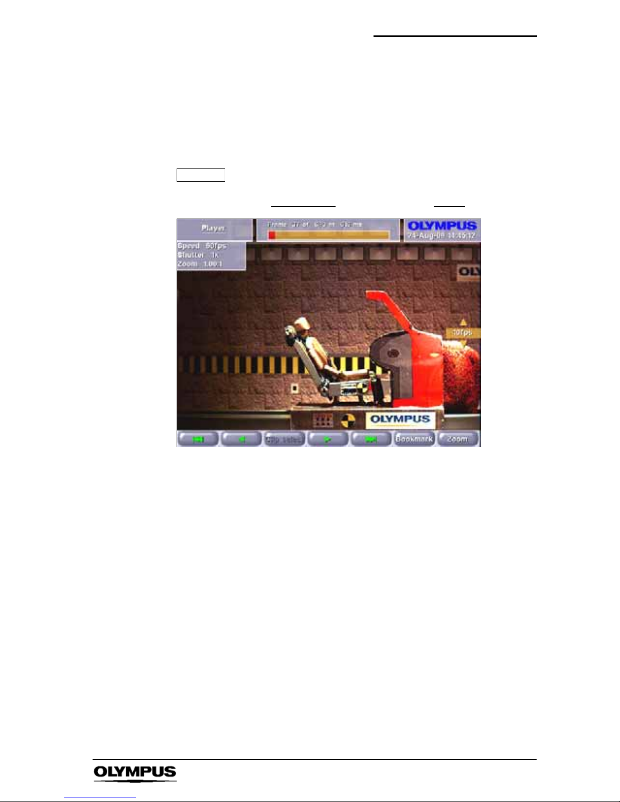
10. Player Menu
This specialised screen allows the user to play back and interact
with the video stored in the circular buffer memory.
Access: i-- SPEED LT Home
' Player
NOTE
Also accessed from the measurement system
Options: |<< < Clip Select
> >>| Bookmark Zoom
S The CDU will display the playback images required by the
player controls
` Player Controls
The controls should be familiar to most users: jump back, play
backwards, play forwards, jump forward.
The jump controls will cause the player to immediately move either
to the next bookmark or to the beginning/end of the memory.
The speed of playback is controlled by the
YBbuttons on the right
hand side of the CDU. The chosen playback speed is indicated in
a label next to these buttons.
` Bookmark Control
This control is used to set bookmarks at points of interest.
Pressing the button when already on a marked frame will remove
the bookmark. Bookmarks are displayed in the progress bar at the
top of the screen. For the convenience of the user, the trigger
frame is automatically given its own bookmark, and this is coloured
differently for clarity.
Page 46

Software reference (CDU) i--SPEED LT
44
i--SPEED LT, i--SPEED 2
` On Screen Information
The player provides a progress bar at the top of the screen to
indicate the relative position within the circular buffer of the
currently displayed frame. This bar is also used to display
bookmarks. In the same display panel as the progress bar is a
numerical description of the frame number, the total number of
frames in memory and the time of the current frame relative to the
startofthememory.
Page 47
Software reference (CDU) i--SPEED LT
45
i--SPEED LT, i--SPEED 2
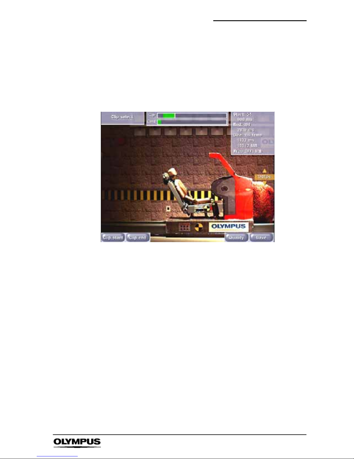
11. Clip Select Menu
This menu makes available all the items which relate to selecting
the video clip to be saved on the compact flash card.
Access: i-- SPEED LT Home
' Player ' Clip Select
Options: Clip start Clip end Player Quality Save
S The CDU will display the playback images required
by the clip select controls
` Clip Start and Clip End Controls
The player controls are used to locate the start and end of the
desired video clip and the Clip Start and Clip End controls are used
to mark the c hosen frames.
` Quality Control
This control permits the user to apply JPEG compression to the
image before it is saved onto the Compact flash card. In this way, it
is possible to increase the number of video images stored on the
card and increase the speed of writing images to the card. The
compression used is compatible with all common viewer software,
including the CODECs used in the Microsoft Windows operating
systems.
Page 48

Software reference (CDU) i--SPEED LT
46
i--SPEED LT, i--SPEED 2
Recording format
Still images
Menu Option Image quality Image size
Compressed Highest quality compressed JPEG 94KB
Uncompressed Highest quality uncompressed JPEG 1400KB
Movies
Menu Option Image quality *Movie size
Compressed Highest quality compressed AVI 11 seconds
Uncompressed Highest quality uncompressed AVI 0.7 seconds
* Approximate maximum movie size when using a 1GB compact
flash card and a video recorded at 1000fps.
NOTE
All figures shown above are approximate as file sizes
will vary depending on image content.
The maximum file size for an AVI movie is 2GB.
` Save Control
If the start and end frames are selected as the same frame, the
save control will cause the camera to save a single bitmap (BMP)
or JPEG image to the card. If more than one frame is chosen, the
camera will save a movie (AVI) file to the card.
` On Screen Information
The Clip Select menu provides a progress bar to indicate the
position in the buffer memory of the currently displayed frame as
well as the start and end frame markers. This bar is also used to
display bookmarks.
In the same display panel as the progress bar is a graphical
representation of the available memory in the card, the total
memory in the c ard and the quantity of memory required for the
currently selected clip.
In a separate display panel is a numerical description of start frame
number relative to the start of the camera’s memory, the number of
frames selected, the size of the chosen clip and the available free
memory in the card.
Page 49

Software reference (CDU) i--SPEED 2
47
i--SPEED LT, i--SPEED 2
Chapter 7 Embedded Software
Reference (CDU)
i- SPEED 2
Introduction
This reference section describes the camera’s embedded software
and its user interface from the viewpoint of the CDU. In this
section, items which are printed like this
signify the name of a sub
menu, controls are described whenever they appear in a menu.
Operation of the CDU menus
To navigate through the menu system, the button nearest the
desired selection is pressed.
When a control is selected, the desired value may be chosen by
using the
Y and B buttons on the right hand side of the screen.
Repeatedly pressing or to press and hold the control button will
cycle through the available values. The current value is displayed
above the control button and also next to the
YBbuttons.
To return to a higher menu, the Back button is pressed. If there is a
requirement for a text free screen, the Text button is used to cycle
the on--screen text through full, time/date only and off options.
The CDU is not high--G rated.
Page 50
Software reference (CDU) i--SPEED 2
48
i--SPEED LT, i--SPEED 2
7.1 Menu Screens
1. OLYMPUS i-- SPEED 2 Splash Screen
This screen is displayed while the camera starts up and configures
the internal software. It contains data on the memory configuration
of the camera, the serial number and the software v ersion number.
To exit this screen, the user must press a button on the CDU.
Page 51
Software reference (CDU) i--SPEED 2
49
i--SPEED LT, i--SPEED 2
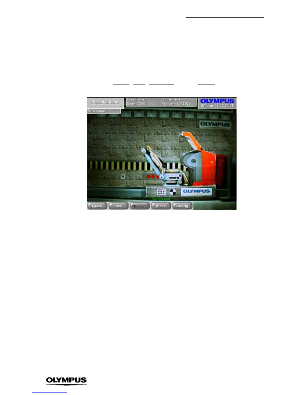
2. i-- SPEED 2 Home Menu
This is the top level or home screen of the menu system. It may be
accessed by pressing the Back button repeatedly from any position
in the menu system.
Options: Quick
Live Playback Mode Config
S The CDU will display a live image
` Mode
This control allows the user to change the operating mode of the
camera into timelapse. This mode is described later in Section 18.
Page 52
Software reference (CDU) i--SPEED 2
50
i--SPEED LT, i--SPEED 2
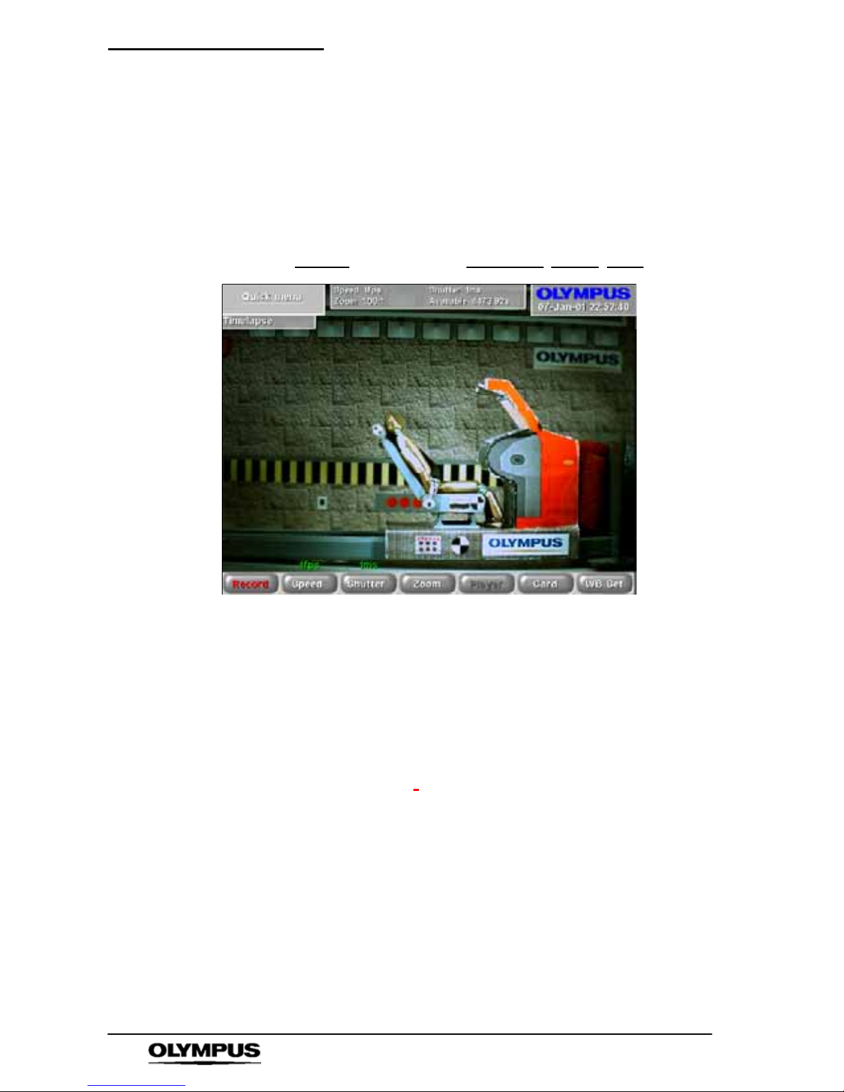
3. Quick Menu
This menu provides rapid access to the most commonly used
functions. All items available through the Quick menu are
accessible elsewhere.
Access: i-- SPEED 2Home
' Quick
Options: Record
Speed Shutter Zoom/Pan Player Card WB Set
S The CDU will display the live image
` Speed Control
This control allows the user to set the frame speed of the camera.
The lowest speed available is 60 frames per second as this is
almost equal to the SVGA display specification. The maximum
speed is fixed to 33,000fps by the design of the sensor and
electronics in the camera.
As described in Chapter 8,
the user will normally need to open the
iris of the lens and/or add more light as the speed is increased.
Further, the image will appear to zoom in as the frame speed is
increased above 1,000 frames per second.
Page 53

Software reference (CDU) i--SPEED 2
51
i--SPEED LT, i--SPEED 2
` Shutter Control
It is sometimes desirable to reduce the time during which the
sensor gathers light (called “exposure time”, “integration time” or
“shutter time”) in order to reduce motion blur and “freeze” the
motion in each frame. The default shutter time is equal to the frame
time, but this may be reduced by this control. The shutter time is
measured as the ratio between frame time and shutter time, e.g.
x10 means that the shutter is open for 1/10 of the frame period. The
shutter period may range from the frame period (x1) to 1/200 of the
frame period (x200), but is subject toa5microsecondlowerlimit
anda1secondupper limit.
The user should note that as the s hutter ratio is increased, the
camera will require more light.
` WB Set Control
This control activates the automatic white balance function. Before
pressing this control, the user must place a pure white reference
(sheet of paper etc.) if front of the camera, completely filling the field
of view. This must not be removed until the white balance is
complete. An on screen message shows the status of the white
balance process.
Please refer to Chapter 8 “Understanding the Olympus
i--SPEED 2”
for a further description.
The control is only available if the white balance mode is set to
automatic.
NOTE
Once this is set, the white balance setting is stored in
the camera’s internal memory.
Page 54
Software reference (CDU) i--SPEED 2
52
i--SPEED LT, i--SPEED 2
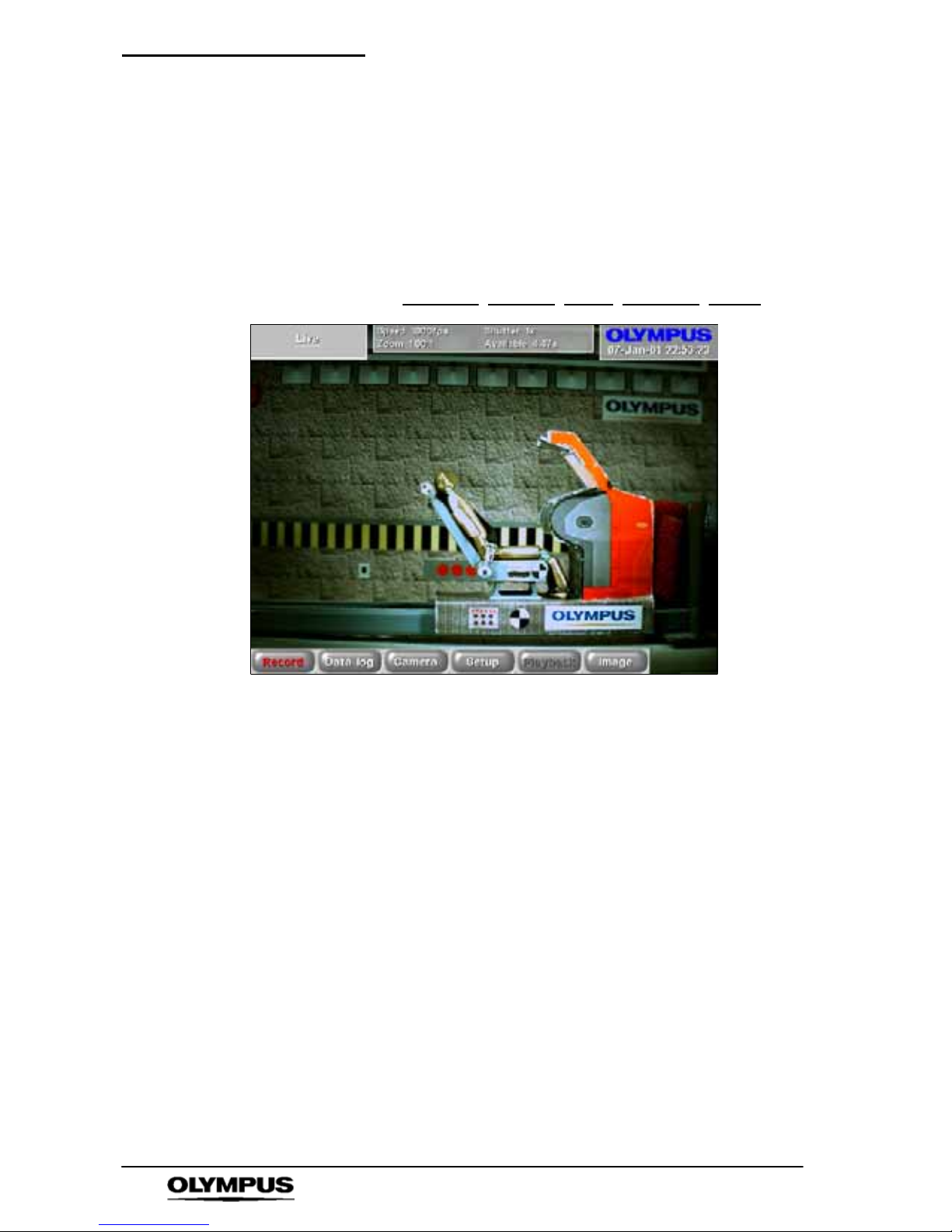
4. Live Menu
This menu makes available all the sub menus items which relate to
the live view systems of the camera.
Access: i-- SPEED 2 Home
' Live
i-- SPEED 2 Home
' Playback ' Live
Options: Record Data Log Camera Setup Playback Image
S The CDU will display the live image
Page 55
Software reference (CDU) i--SPEED 2
53
i--SPEED LT, i--SPEED 2
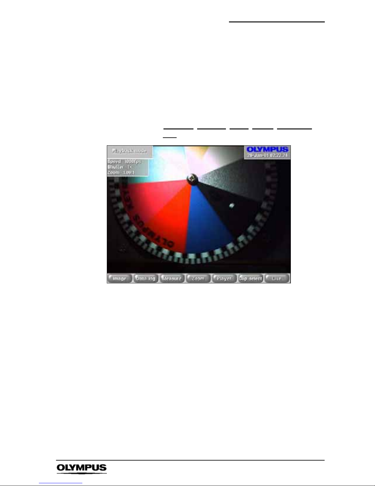
5. Playback Menu
This menu makes available all the items which relate to the
playback view systems of the camera. The menu is not available
until a recording has been made.
Access: i-- SPEED 2 Home
' Playback
i-- SPEED 2 Home
' Live ' Playback
Options: Image Data Log Measure Zoom Player Clip Select
Live
S Automatically appears after recording has stopped and
displays the playback image.
` Image Control
This control activates the image processing menu, see section 11.
Page 56
Software reference (CDU) i--SPEED 2
54
i--SPEED LT, i--SPEED 2
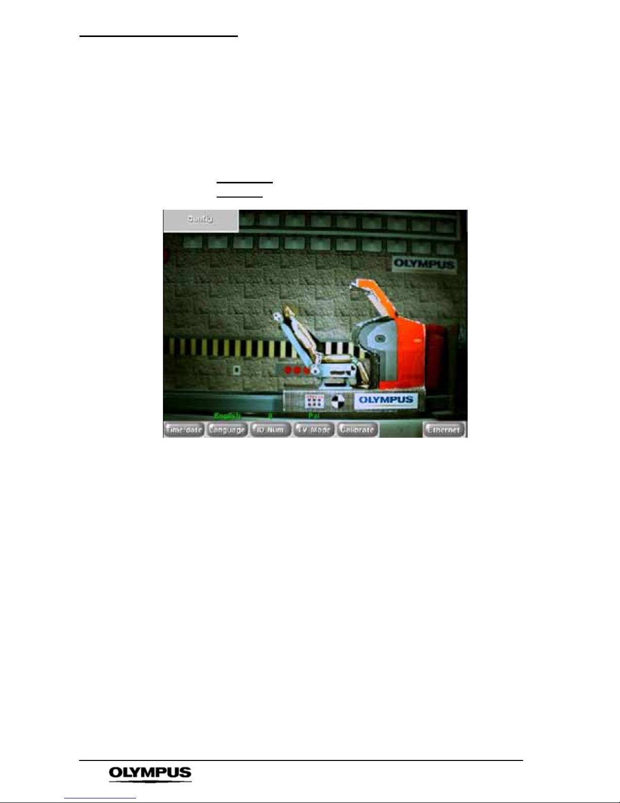
6. Config Menu
This menu makes available all the items which relate to the
configuration of the camera.
Access: i-- SPEED 2 Home
' Config Menu
Options: Time/Date Language Camera ID TV Monitor Calibrate
Ethernet
` Language Control
This control permits the user to set the language in which the
menus are displayed. The language of the information tiles and
control value display is not changed.
` Camera ID Control
The Olympus i-- SPEED 2 camera is capable of connection to an
Ethernet network. It is possible to connect more than one camera
and, whilst the cameras are uniquely identified by their TCP/IP
address, it is sometimes useful to have a simple user settable ID
tag which is kept with the downloaded video. This control allows
the setting of this tag.
` TV Monitor Control
The composite video output connector (BNC) is able to provides
either NTSC or PAL and this selection is made by this control.
Page 57

Software reference (CDU) i--SPEED 2
55
i--SPEED LT, i--SPEED 2
` Calibrate Sensor Control
In common with all CMOS sensor chips, the Olympus i-- SPEED 2
sensor requires a calibration system to remove fixed pattern noise.
The standard Olympus i-- SPEED 2 provides a fully automatic
off--chip calibration system which operates in under a second. This
system includes a mechanical shutter which removes the
requirement for the user to manually cover the lens as is found on
less capable cameras. The shutter gives a characteristic click
sound when it operates. Manual operation of the system is not
usually necessary, but may be required in very high ambient
temperatures. Further discussion may be found in Chapter 8
“Understanding the Olympus i -- SPEED 2’’.
This control allows the user to manually trigger the calibration
system.
NOTE
To calibrate the i -- SPEED 2 HG the lens cap should be
fitted before depressing Calibrate sensor.
` Ethernet
When using multiple cameras in conjunction with the PC software,
each camera will need to have a unique TCP/IP address. Every
i--SPEED 2 camera has a default address of 192.168.0.54. This
control allows this address to be configured for each camera on the
network. Once set, the TCP/IP address will be stored in the
cameras memory.
Page 58
Software reference (CDU) i--SPEED 2
56
i--SPEED LT, i--SPEED 2
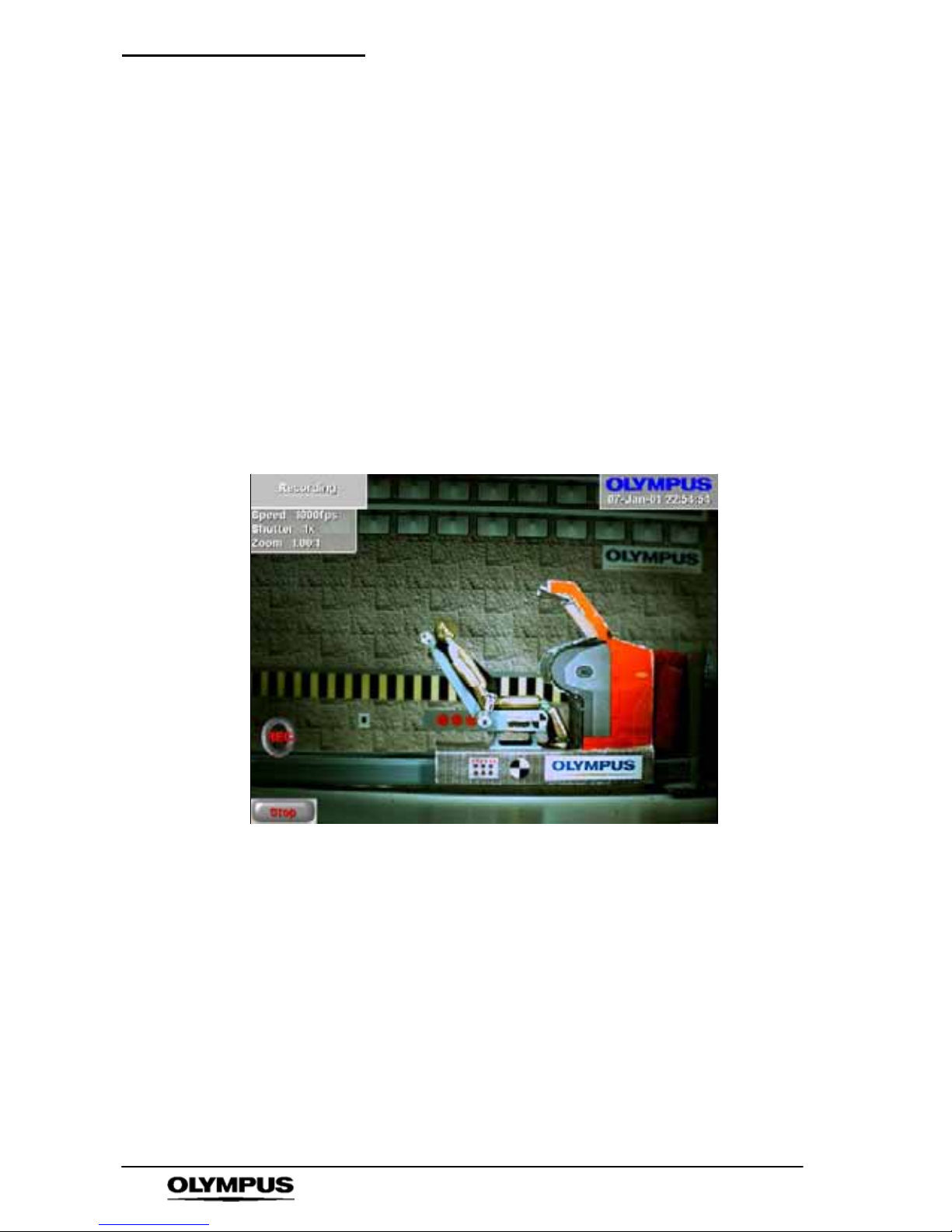
7. Recording Menu
When this menu is displayed, the Olympus i-- SPEED 2 is recording
video into its circular buffer. The record action is confirmed by the
presence of an icon displaying “REC” in red. When a trigger signal
is received and the camera is working through the length of its
trigger counter, the animation is changed to read ‘TRIG
’ in green.
When recording has stopped, whether by the trigger or the STOP
control, the camera will automatically present the Playback Menu
and thereby display the first recorded image in the memory.
Access: i-- SPEED 2 Home
' Quick ' Record
i-- SPEED 2 Home
' Live ' Record
Options:STOP
S The CDU will display the live image
` STOP Control
This control will cause the camera to stop recording immediately,
regardless of the setting of the trigger position.
Page 59
Software reference (CDU) i--SPEED 2
57
i--SPEED LT, i--SPEED 2
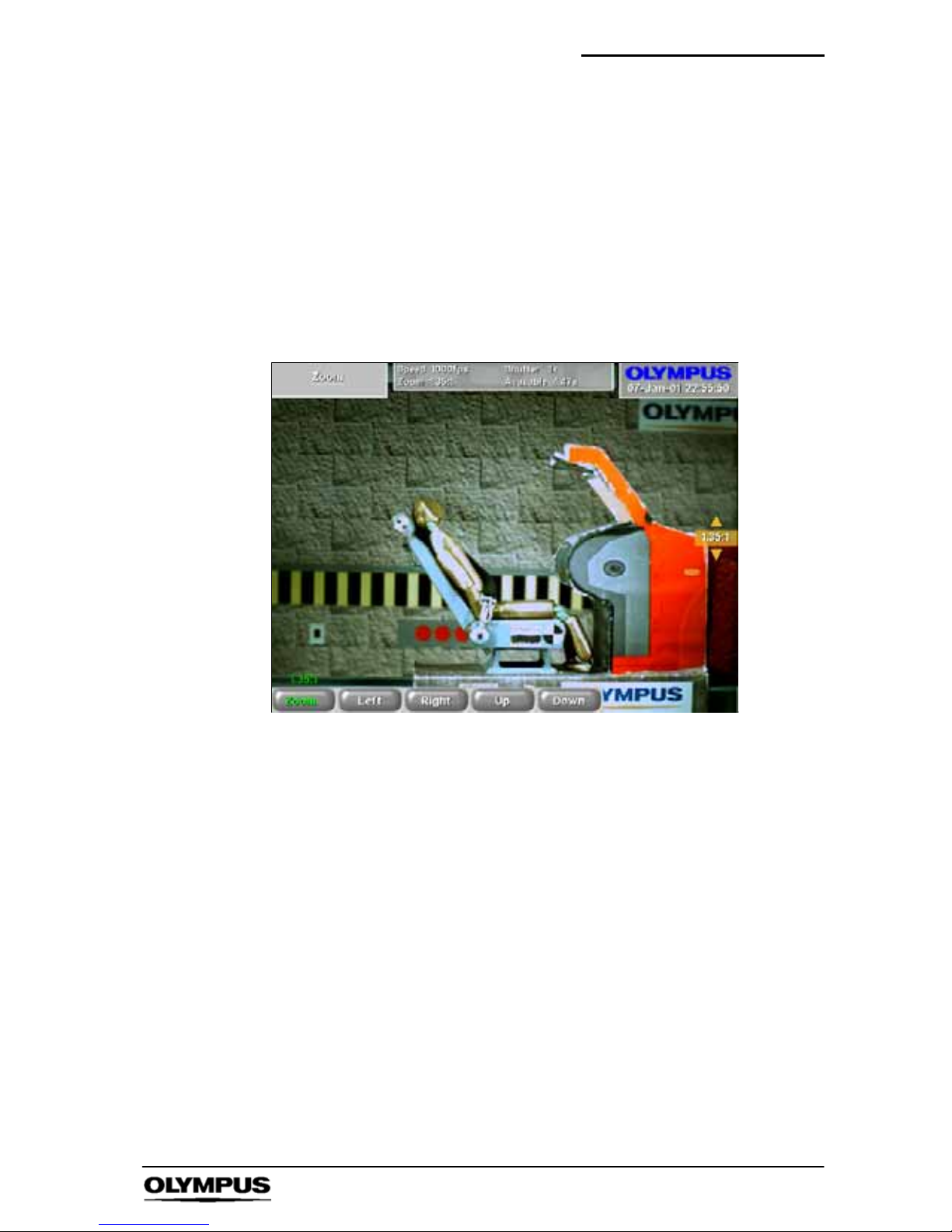
8. Zoom Menu
This menu provides access to the controls of the built--in zoom
engine.
Access: i-- SPEED 2 Home
' Quick ' Zoom
i-- SPEED 2 Home
' Playback ' Zoom
i-- SPEED 2 Home
' Live ' Playback ' Zoom
i-- SPEED 2 Home
' Live ' Camera ' Zoom
Options: Zoom Pan Left Pan Right Pan Up Pan Down
S The CDU will display the live or playback image
depending on the route taken to activate the menu
` Zoom Control
The Olympus i-- SPEED 2 camera has a built--in zoom engine
which can electronically magnify the video image by up to 10 times.
The user may adjust the level of zoom using the zoom control in
this menu.
It should be noted that the z oom engine is automatically operated
when high frame rates result in the active area of the sensor being
reduced or when the “square” economy mode is selected. In these
circumstances, the user may still zoom further into the zoomed
image, but the 10 times limit is applied to the total zoom employed.
` Pan Control
For the convenience of the user, pan controls are also provided.
These are individually disabled when the limit of the pan in a given
direction is reached, and all are disabled when the zoom engine is
turned off (1:1).
Page 60
Software reference (CDU) i--SPEED 2
58
i--SPEED LT, i--SPEED 2
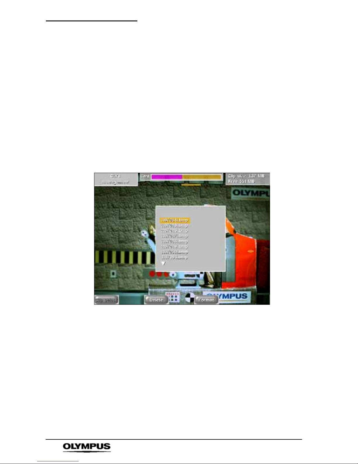
9. Card Management Menu
This menu makes available the items which relate to the
management of the removable compact flash memory card.
The screen includes a list of the files on the card and one of these
will be highlighted by a selection bar.
Automatically appears after saving a file
Access: i-- SPEED 2 Home
' Quick ' Card
Options: Clip select Delete Format
The CDU will display the splash screen logo and card directory.
` Clip select
This control is used to access the video and still image compact
flash card save menu.
` Delete Control
This control is used to delete the selected file from the card. The
user is protected from error by a confirmation question.
` Format Control
The user is able to format the card. This will delete all the data on
the card and also prepare a new card for its first use. The user is
protected from error by a confirmation question.
Page 61
Software reference (CDU) i--SPEED 2
59
i--SPEED LT, i--SPEED 2
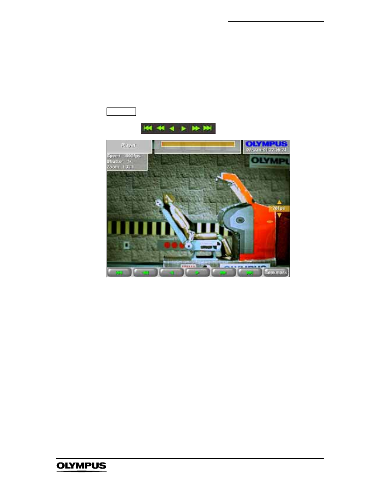
10. Player Menu
This specialised screen allows the user to play back and interact
with the video stored in the circular buffer memory.
Access: i-- SPEED 2 Home ' Playback ' Player
i-- SPEED 2 Home
' Live ' Playback ' Player
NOTE
Also accessed from the measurement system
Options:
Bookmark
S The CDU will display the playback images required by the
player controls
` Player Controls
The controls should be familiar to most users: jump back, rewind,
play backwards, play forwards wind forwards, jump forward.
The jump controls will cause the player to immediately move either
to the next bookmark or to the beginning/end of the memory.
The speed of playback is controlled by the
YBbuttons on the right
hand side of the CDU. The chosen playback speed is indicated in
a label next to these buttons.
` Bookmark Control
This control is used to set bookmarks at points of interest.
Pressing the button when already on a marked frame will remove
the bookmark. Bookmarks are displayed in the progress bar at the
top of the screen. For the convenience of the user, the trigger
frame is automatically given its own bookmark, and this is coloured
differently for clarity.
Page 62

Software reference (CDU) i--SPEED 2
60
i--SPEED LT, i--SPEED 2
` On Screen Information
The player provides a progress bar at the top of the screen to
indicate the relative position within the circular buffer of the
currently displayed frame. This bar is also used to display
bookmarks. In the same display panel as the progress bar is a
numerical description of the frame number, the total number of
frames in memory and the time of the current frame relative to the
startofthememory.
Page 63
Software reference (CDU) i--SPEED 2
61
i--SPEED LT, i--SPEED 2
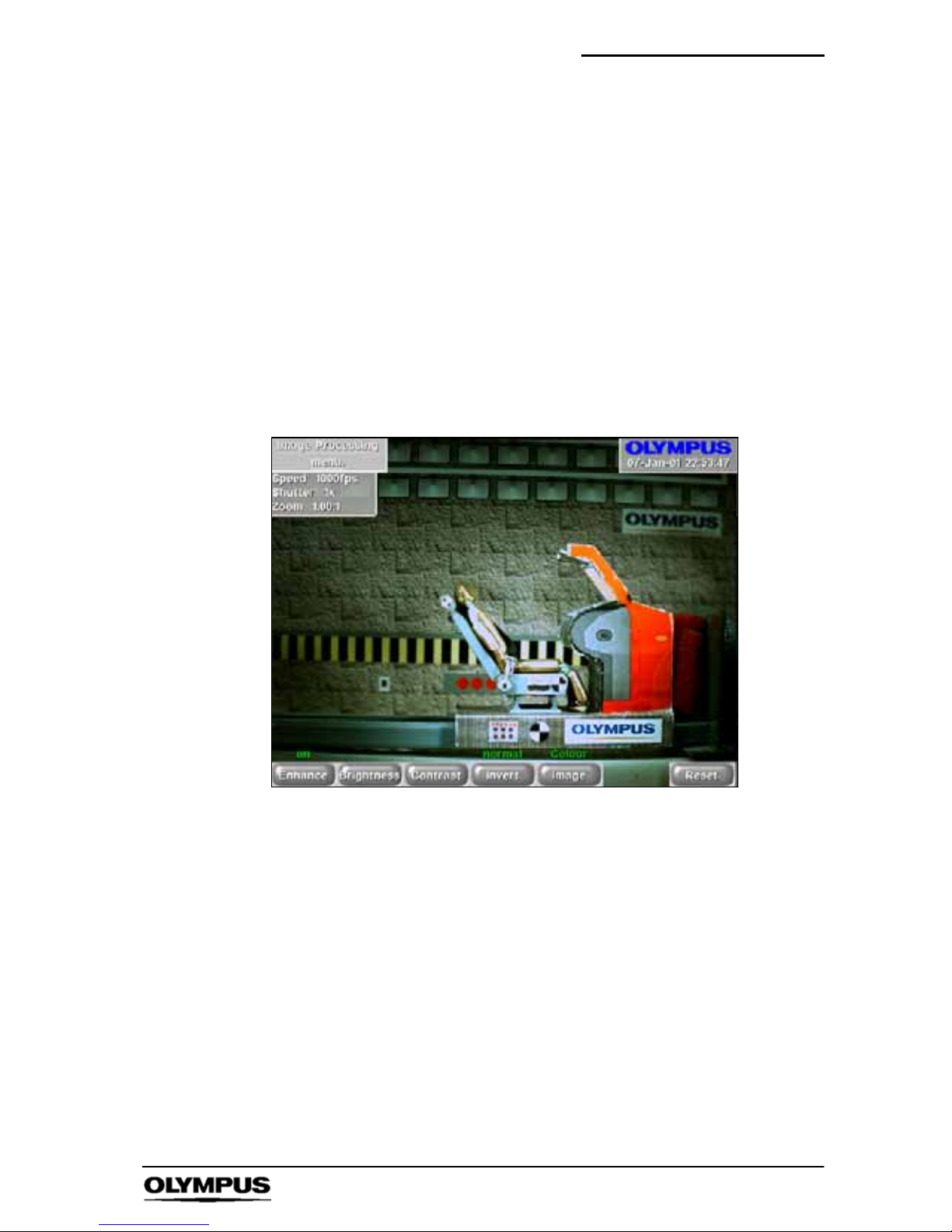
11. Image Processing Menu
This menu enables the user to apply image processing to the live
picture on the CDU screen to improve the visibility of details in the
image. Any processing applied via this menu is also applied to the
images saved onto the Compact flash card. If the Ethernet
connection is invoked subsequent to the application of image
processing, the images transferred to the PC will also include this
processing.
Access: i--SPEED 2 Home
' Live ' Camera ' Image
i--SPEED 2 Home
' Playback ' Image
i--SPEED 2 Home
' Live ' Playback ' Image
Options: Enhance Brightness Contrast Invert Image Reset
` Enhance Control
The Olympus i--SPEED 2 is able to digitally enhance the on --screen
image. This enhancement is based on two-- pole, two--dimensional
edge detection and is carefully phase matched to the video signal.
This control adjusts the quantity of enhancement added.
` Brightness Control
The controls in this menu permit the user to alter the “brightness” of
the image. This control mimics the operation of the ”brightness”
control in CRT video monitors by altering the black level of the
image. Although this alters the appearance of the image, it is often
helpful in making detail hidden in dark areas become more visible.
Since a video image is made of the primary optical colours, red,
green and blue, these colours may be individually adjusted, or all
may be adjusted together.
Page 64

Software reference (CDU) i--SPEED 2
62
i--SPEED LT, i--SPEED 2
` Contrast Control
The controls in this menu permit the user to alter the “contrast” of
the image. This control mimics the operation of the ”contrast”
control in CRT video monitors by linearly adding gain to the image.
This is often helpful in making obscure detail become more visible
and compensating for poor or harsh lighting conditions. Since a
video image is made of the primary optical colours, red, green and
blue, these colours may be individually adjusted, or all may be
adjusted together. Individual adjustment is also useful for altering
the colour balance of an image, to compensate for (or imitate)
coloured ambient illumination.
` Invert Control
This control permits the user to invert the colours of the image, like
a photographic film negative. Although this dramatically alters the
appearance of the image, it is sometimes helpful in making an
obscure detail become more v isible. Since a video image is made
of the primary optical colours, red, green and blue, these colours
may be individually inverted, or all may be inverted together.
` Image Control
In the colour models of i--SPEED 2, this control enables the user to
convert the colour image to monochrome (black and white). This is
sometimes useful to make the image clearer when bright colours in
the scene are cluttering the image.
` Reset Control
All of the image processing functions, including Enhance,
Brightness, Contrast, Invert and Image may be applied to the
picture simultaneously. It is therefore possible to lose track of
which controls have caused what effects, so a reset control is
available to set Brightness, Contrast, Invert and Image to their
default values.
Page 65
Software reference (CDU) i--SPEED 2
63
i--SPEED LT, i--SPEED 2
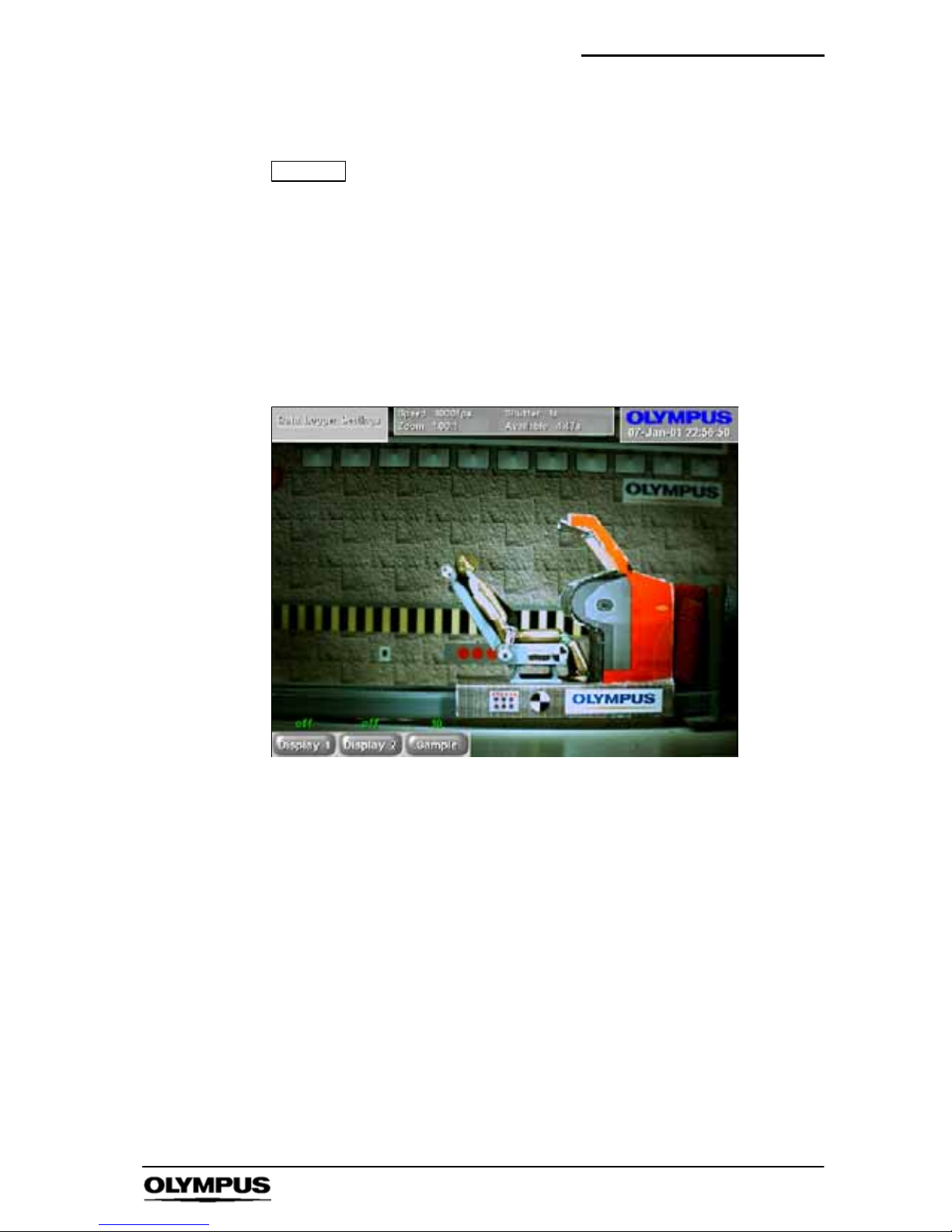
12. Data Log Menu
NOTE
This menu is not available in timelapse mode.
This menu makes available all the items which relate to the
analogue input signal data logger and data display.
Access: i-- SPEED 2 Home
' Live ' Data Log
i-- SPEED 2 Home
' Playback ' Data Log
i-- SPEED 2 Home
' Live ' Playback ' Data Log
Options: Display 1 Display 2 Sample
S The CDU will display the live or playback image
depending on the route taken to activate the menu
` Sample Control
The sample rate of the user data logger may be adjusted by this
control. The sampling rate is expressed in terms of samples per
frame and the available range is from 1 to 100, but there is an
upper limit of 100,000 samples per second.
` Display 1 and 2 Controls
The analogue signal data which is sampled by the user data logger
may be displayed in graphical format on the CDU screen and these
controls allow the channels to be individually switched on and off.
Page 66
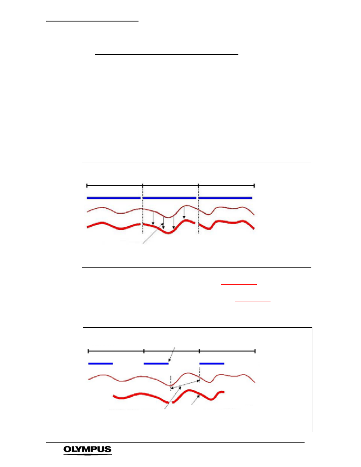
Software reference (CDU) i--SPEED 2
64
i--SPEED LT, i--SPEED 2
Data Logger Timing -- an explanation
The data logger records data for the entirety of each frame period
regardless of the shutter setting. This feature is included so that
the user is able to detect events which happen faster than the
frame period and which may be blurred, missed by the video
recording (or missed if a short shutter time is used).
When a short shutter time is employed, a question arises as to
what data should be logged. The diagram below shows the action
of the data logger with a shutter setting of x1. In this example, it
can be seen that the sensor gathers an image for the whole frame
period and the data logger gathers data for the same period. In this
way, the data and the image are correlated.
Frame period
Sensor integration
Incoming signal
Signal recorded
All of the data is collected while
the camera collects an image
SHUTTER x1
If the shutter is now increased to x2, the i
-- SPEED 2 still gathers
data for an entire frame period, but it only gathers the image for half
the frame period. It should be noted that the i
-- SPEED 2 records
data from the time in the preceding frame when the shutter closes
through to the time in the current frame when the shutter closes.
Frame period
Sensor integration
Incoming signal
Signal recorded
SHUTTER x2
...this section of data
has not yet come
into the camera...
At the point picture
collection finishes here...
...so it is included
in the next frame.
Page 67
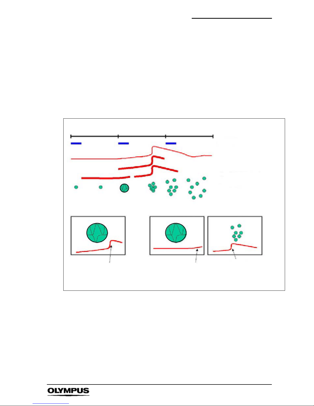
Software reference (CDU) i--SPEED 2
65
i--SPEED LT, i--SPEED 2
It may be wondered why the data is not recorded over the current
frame period. This action would lead to the display of data which
occurred after the sensor had collected an image. An example is
given of an explosion. In the first CDU image, the display shows
the ball expanding and cracking, but the data shows an explosion.
This is incorrect, because the data is not explained by the image.
In the second CDU image, the data s hows the ball expanding and
cracking and this is supported by the data beginning to rise . The
next CDU image correctly shows the ball after the explosion and
the data from the explosion is displayed in this frame.
Frame period
Sensor integration
Incoming signal
Signal recorded incorrectly
SHUTTER x4 -- explosion example
Graph of explosion
which is not displayed
on image
CDU display
incorrect recording
CDU display
correct recording
CDU display
next frame
Graph of expansion
which is not displayed
on image
Graph of explosion
which is explained by
image
Signal recorded correctly
Explosion event
Page 68
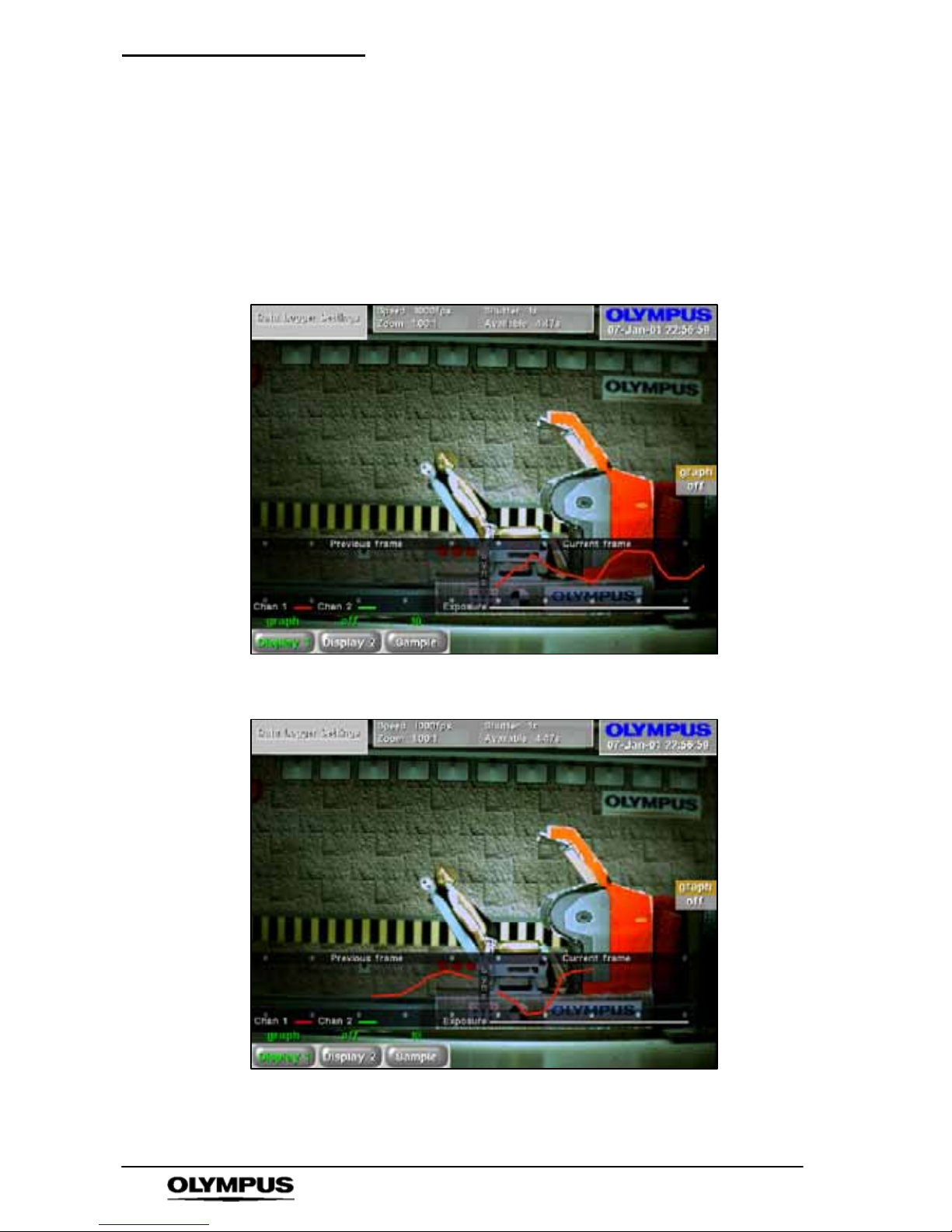
Software reference (CDU) i--SPEED 2
66
i--SPEED LT, i--SPEED 2
This point is somewhat esoteric but is none the less very important.
In order to fully explain the timing of the data logging, the data
display is presented on the CDU along with a reference frame
diagram. The diagram shows the previous frame, the current frame
and the exposure period. The data log is also shown and it is
drawn in the position from which the data was collected. Thus it will
be seen that a shutter of x1 c auses collection from the current
frame,
while a shutter of x2 causes collection from the previous as well as
the current frame.
Since the end of data collection is synchronised with the end of the
exposure period, it will be understood that a shutter of x200 causes
collection of almost all the data from the previous frame.
Page 69
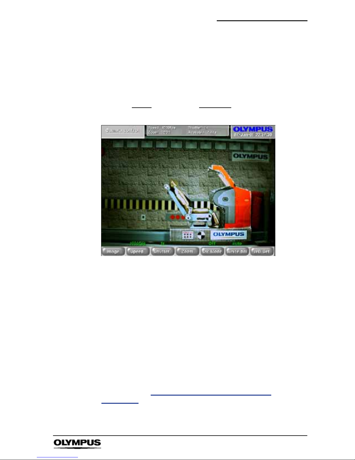
Software reference (CDU) i--SPEED 2
67
i--SPEED LT, i--SPEED 2
13. Camera Menu
This menu makes available all the items which relate to the detailed
control of the video processing chain of the camera.
Access: i-- SPEED 2 Home
' Live ' Camera
Options: Image
Speed Shutter Zoom/Pan Dynamic Range
White Ba l WB Set
S The CDU will display the live image
` Image Control
This menu enables the user to apply image processing to the live
picture on the CDU screen to improve the visibility of details in the
image. Any processing applied via this menu is also applied to the
images saved onto the Compact flash card.
` Speed Control
This control allows the user to set the frame speed of the camera.
The lowest speed available is 60 frames per second as this is
almost equal to the SVGA display specification. The maximum
speed is fixed to 33,000fps by the design of the sensor and
electronics in the camera.
As described in Chapter 8 “Understanding the
Olympus
i--SPEED
2” the user will normally need to open the iris of the lens
and/or add more light as the speed is increased. Further, the
image will appear to zoom in as the frame speed is increased
above 1,000 frames per second.
Page 70

Software reference (CDU) i--SPEED 2
68
i--SPEED LT, i--SPEED 2
` Shutter Control
It is sometimes desirable to reduce the time during which the
sensor gathers light (called “exposure time”, “integration time” or
“shutter time”) in order to reduce motion blur and “freeze” the
motion in each frame. The default shutter time is equal to the frame
time, but this may be reduced by this control. The shutter time is
measured as the ratio between frame time and shutter time, e.g.
x10 means that the shutter is open for 1/10 of the frame period.
The shutter period may range from the frame period (x1) to 1/200 of
the frame period (x200), but is subject toa5microsecondlower
limitanda1secondupper limit.
The user should note that as the s hutter ratio is increased, the
camera will require more light.
` Dynamic Range Control
The i -- SPEED 2’s image sensor is capable of detecting light in a
non-- linear fashion, which permits each pixel to individually reduce
its sensitivity with increasing light. This effect allows the sensor to
“see” in very bright and dark areas simultaneously and this is
known as “dynamic range extension”. There are several levels of
dynamic range extension. Further discussion may be found in
Chapter 8 “Understanding the Olympus
i--SPEED 2”.
` White Bal Control
The Olympus i-- SPEED 2 provides two types of white balance,
pre--set and automatic. Several pre--set white balance settings are
provided, based on light source technologies found in the Olympus
range of industrial light sources.
The automatic function relies on the user placing a pure white
reference (sheet of paper etc.) if front of the camera, completely
filling the field of view and then pressing the WB Set button. This
paper must not be removed until the white balance is complete. An
on screen message shows the status of the white balance process.
The balance achieved is remembered by the camera while
switched off.
NOTE
This control is not available in monochrome cameras.
Page 71

Software reference (CDU) i--SPEED 2
69
i--SPEED LT, i--SPEED 2
` WB Set Control
This control activates the automatic white balance function. Before
pressing this control, the user must place a pure white reference
(sheet of paper etc.) if front of the camera, completely filling the field
of view. This must not be removed until the white balance is
complete. An on screen message shows the status of the white
balance process.
Please refer to Chapter 8 “Understanding the Olympus i--SPEED
2”
for a further description.
NOTE
The control is only available if the white balance mode
is set to automatic.
Once set, the white balance values will be stored in
non-- volatile memory. Thus if camera power is removed,
the camera will return to the user set white balance
values.
Page 72
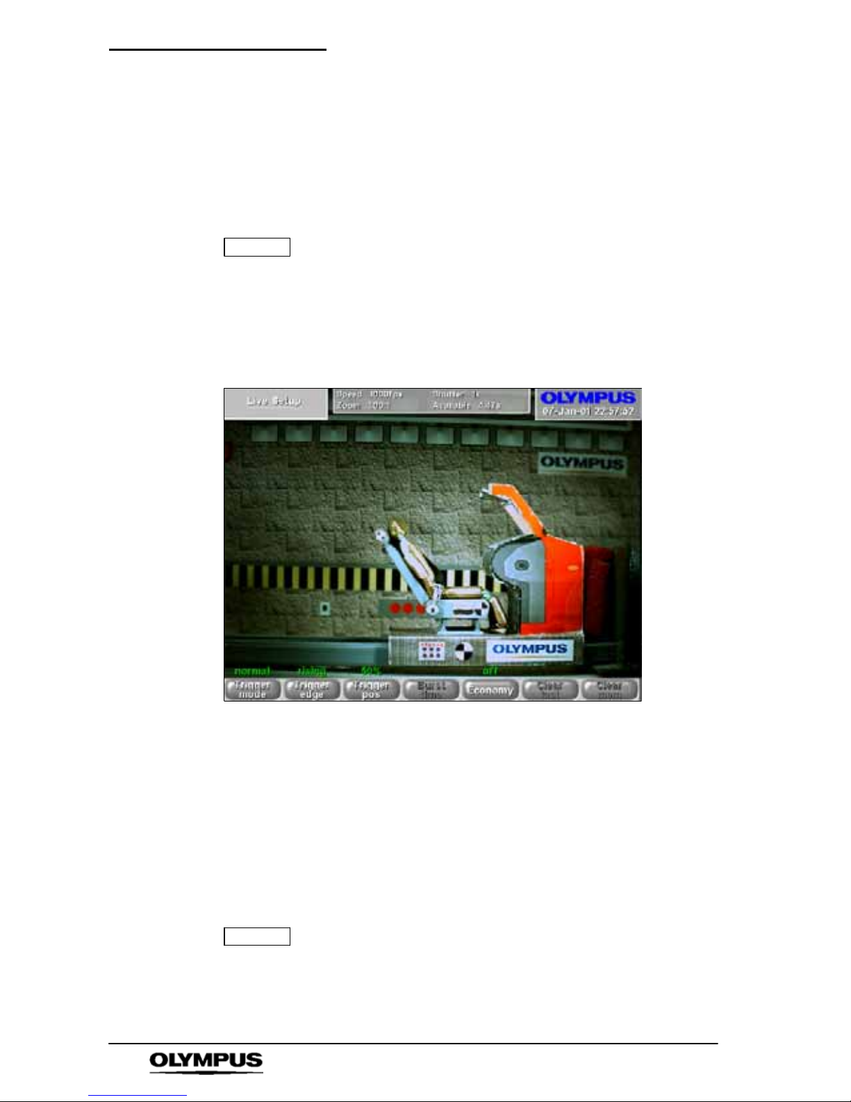
Software reference (CDU) i--SPEED 2
70
i--SPEED LT, i--SPEED 2
14. Live Setup Menu
This menu makes available all the items which relate to the live
view systems of the camera. It would be of benefit to read Chapter
8 “Understanding the Olympus i -- SPEED 2” for further descriptions
on several of the terms and phrases used in this section.
NOTE
This menu is not available in Timelapse mode.
Access: i-- SPEED 2 Home
' Live ' Setup
i-- SPEED 2 Home
' Playback ' Live ' Setup
Options: Trig Mode Trig Edge Trig Pos Burst Time
Economy Clear Last Clear Mem
S The CDU will display the live image
` Trigger Mode Control
This control is used to change the camera into Record On
Command (ROC) mode or Burst Record On Command (BROC)
mode.
` Trigger Edge Control
This control sets the trigger detection system to wait for a rising
edge or a falling edge on the trigger input connection.
NOTE
This control is not available in ROC mode, since ROC is
not edge triggered.
This value is stored in non--volatile memory. After a
power cycle, it will be set to the last used position.
Page 73

Software reference (CDU) i--SPEED 2
71
i--SPEED LT, i--SPEED 2
` Trigger Position Control
This control sets the length of the trigger delay, so that the trigger
point will appear at a user-- settable position in the recorded video
clip. With the trigger position at 0%, the trigger delay is equal to the
length of the circular buffer and the trigger point will appear at the
beginning of the video clip. With the trigger position at 100%, the
trigger counter is set to zero and the recording will stop immediately
the trigger is activated, thus the trigger point will appear at the end
of the video clip. There are a number of options available in
between 0% and 100%.
NOTE
This control is not available in ROC and BROC modes.
` Burst Time Control
This sets the length of the bursts recorded when the trigger is
activated in BROC mode.
NOTE
This control is not available in normal trigger or ROC
modes.
` Economy Control
It will be noted that many high speed events are primarily horizontal
or vertical in nature and so the edges of the screen often contain no
useful video information. It is also sometimes desired to have a
longer record time than that given by the available memory option.
This control addresses both of these issues by causing the camera
to use a central subsection of the sensor, rather than the maximum
available area. This has the effect of reducing the number of pixels
recorded in each frame and so effectively increasing the record
time available.
Where possible, the zoom engine will return the image to full
screen.
` Clear Last Control
Pressing this control deletes the last burst recorded in ROC or
BROC mode.
NOTE
This control is not available in normal trigger mode, or if
no burst is available for deletion.
` Clear Mem Control
Pressing this control deletes the entire contents of the memory,
permitting further use of the ROC or BROC modes.
NOTE
This control is not available in normal trigger mode, or if
no burst is available for deletion.
Page 74
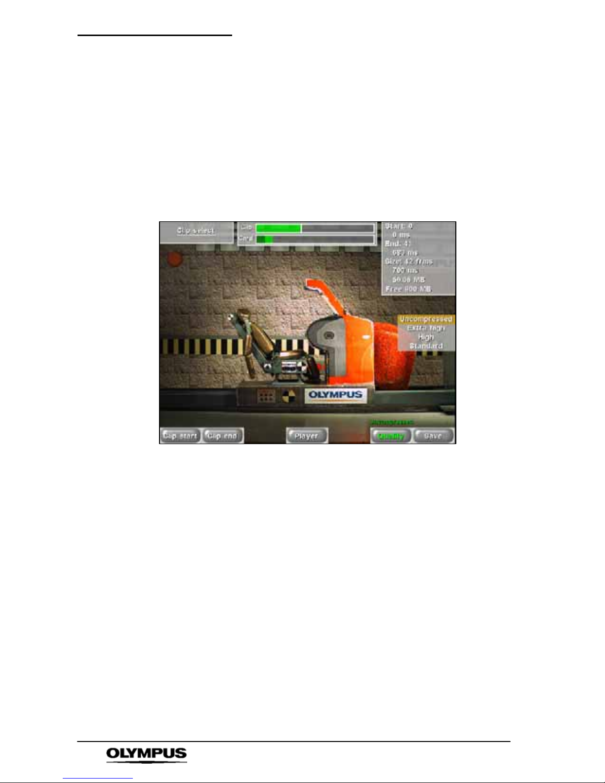
Software reference (CDU) i--SPEED 2
72
i--SPEED LT, i--SPEED 2
15. Clip Select Menu
This menu makes available all the items which relate to selecting
the video clip to be saved on the compact flash card.
Access: i-- SPEED 2 Home
' Playback ' Clip Select
i-- SPEED 2 Home
' Live ' Playback ' Clip Select
i-- SPEED 2 Home
' Quick ' Card ' Clip Select
Options: Clip start Clip end Player Quality Save
S The CDU will display the playback images required
by the clip select controls
` Clip Start and Clip End Controls
The player controls are used to locate the start and end of the
desired video clip and the Clip Start and Clip End controls are used
to mark the c hosen frames.
` Player Controls
The controls should be familiar to most users: jump back, rewind,
play backwards, play forwards wind forwards, jump forward.
The jump controls will cause the player to immediately move either
to the next bookmark or to the beginning/end of the memory.
Page 75

Software reference (CDU) i--SPEED 2
73
i--SPEED LT, i--SPEED 2
` Quality Control
This control permits the user to apply JPEG compression to the
image before it is saved onto the Compact flash card. In this way, it
is possible to increase the number of video images stored on the
card and increase the speed of writing images to the card. The
compression used is compatible with all common viewer software,
including the CODECs used in the Microsoft Windows operating
systems.
Recording format
Still images
Menu Option Image quality Image size
Extra high Highest quality compressed JPEG 94KB
High Medium quality compressed JPEG 56KB
Standard Lowest quality compressed JPEG 28KB
Uncompressed Highest quality uncompressed JPEG 1400KB
Movies
Menu Option Image quality *Movie size
Extra high Highest quality compressed AVI 11 seconds
High Medium quality compressed AVI 17 seconds
Standard Lowest quality compressed AVI 35 seconds
Uncompressed Highest quality uncompressed AVI 0.7 seconds
* Approximate maximum movie size when using a 1GB compact
flash card and a video recorded at 1000fps.
NOTE
All figures shown above are approximate as file sizes
will vary depending on image content.
The maximum file size for an AVI movie is 2GB.
Page 76

Software reference (CDU) i--SPEED 2
74
i--SPEED LT, i--SPEED 2
` Save Control
If the start and end frames are selected as the same frame, the
save control will cause the camera to save a single bitmap (BMP)
or JPEG image to the card. If more than one frame is chosen, the
camera will save a movie (AVI) file to the card.
` On Screen Information
The Clip Select menu provides a progress bar to indicate the
position in the buffer memory of the currently displayed frame as
well as the start and end frame markers. This bar is also used to
display bookmarks.
In the same display panel as the progress bar is a graphical
representation of the available memory in the card, the total
memory in the c ard and the quantity of memory required for the
currently selected clip.
In a separate display panel is a numerical description of start frame
number relative to the start of the camera’s memory, the number of
frames selected, the size of the chosen clip and the available free
memory in the card.
Page 77
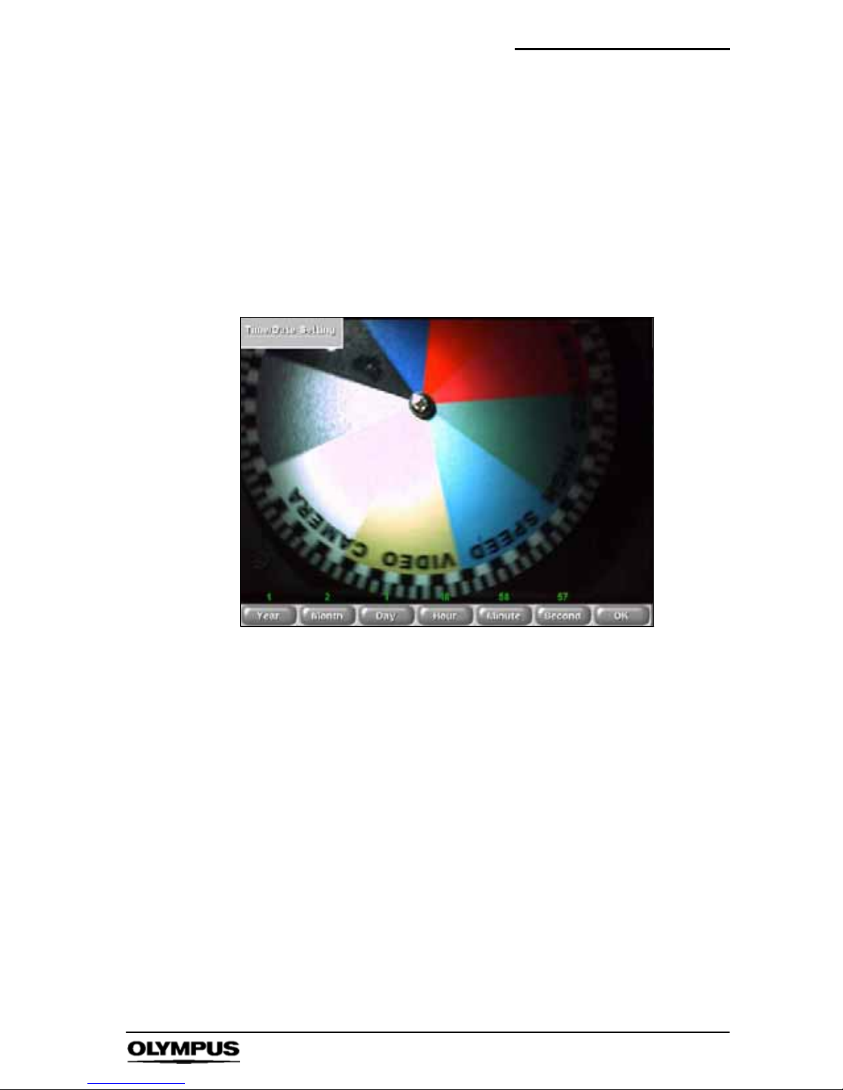
Software reference (CDU) i--SPEED 2
75
i--SPEED LT, i--SPEED 2
16. Time / Date Setting Menu
This menu permits the setting of the time and date of the on-- board
clock of the camera.
When the appropriate time and date have been set, the OK button
should be pressed.
Access: i-- SPEED 2 Home
' Config ' Time/Date
Options: Year Month Day Hour Minute Second OK
S The CDU will display the splash screen logo
` OK Control
This control confirms the numerical entry just made and also
returns to the previous menu.
Page 78
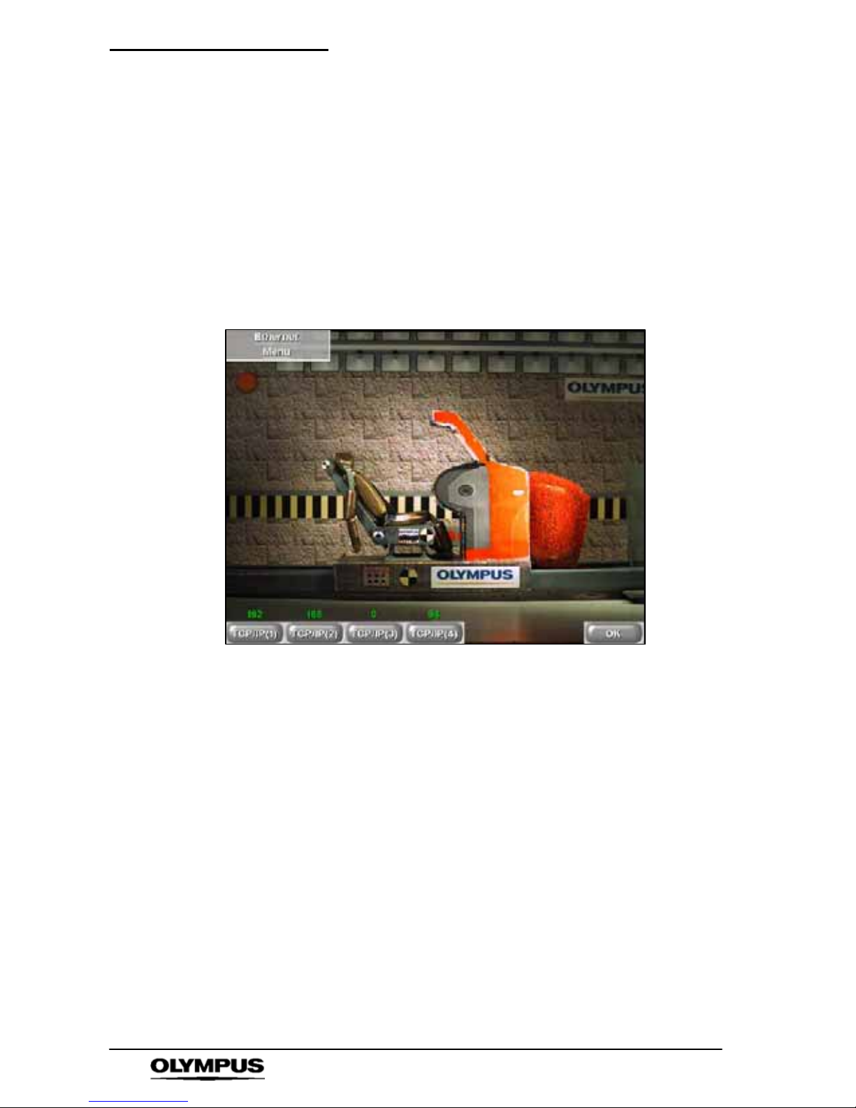
Software reference (CDU) i--SPEED 2
76
i--SPEED LT, i--SPEED 2
17. Ethernet Menu
Access: i-- SPEED 2 Home
' Config ' Ethernet
These controls permit the setting of the TCP/IP address of the
on-- board Ethernet controller of the camera. The choice of address
is dependant on the individual network being used and should be
chosen by the network administrator. When the appropriate
address has been set, the OK button should be pressed.
Options: TCP/IP(1) TCP/IP(2) TCP/IP(3) TCP/IP(4) OK
` OK Control
This control confirms the numerical entry just made and also
returns to the previous menu.
Page 79

Software reference (CDU) i--SPEED 2
77
i--SPEED LT, i--SPEED 2
18. Timelapse mode
In addition to its normal function as a high speed video camera, the
Olympus i -- SPEED 2 is able to operate as a timelapse camera. In
timelapse mode, operation is similar to normal mode, with a few
necessary exceptions.
The normal trigger functions, ROC, BROC and the data logger
functions are not available, so the Live Set-- up menu is deleted.
The speed is expressed either as frames per second or seconds
per frame, depending on the speed chosen. The shutter is
expressed in time, rather than shutter ratio. Speed and angular
velocity measurement are not available.
7.2 Measurement system
The Olympus i-- SPEED 2 camera has a built-- in measurement
system which is based on the principle of comparative
measurement whereby measurement is achieved by entering the
size of a known object in the image and then comparing this with
thesizetobemeasured.
The measurement suite is intended to give a good indication of
relative object distance, speed and angle. However, due to the
number of variable factors involved, no guarantee of measurement
accuracy can be given.
IMPORTANT: The entire reference measurement and the entire
measurement of interest must be coplanar, in a plane orthogonal to
the axis of the camera.
This means that for distance and speed measurements, the scene
must contain an object whose size is accurately known. Also, this
object must be the same distance from the lens as the object being
measured.
Furthermore, the start and end points of the known measurement
and the start and end points of the measurement of interest must all
be the same distance from the camera. For angle and angular
velocity measurements, the origin, start and end points of the
measurement must all be the same distance from the camera.
The accuracy of measurement depends on the conditions above
being fulfilled and on the skill of the operator in placing the on
screen cursors accurately.
Page 80
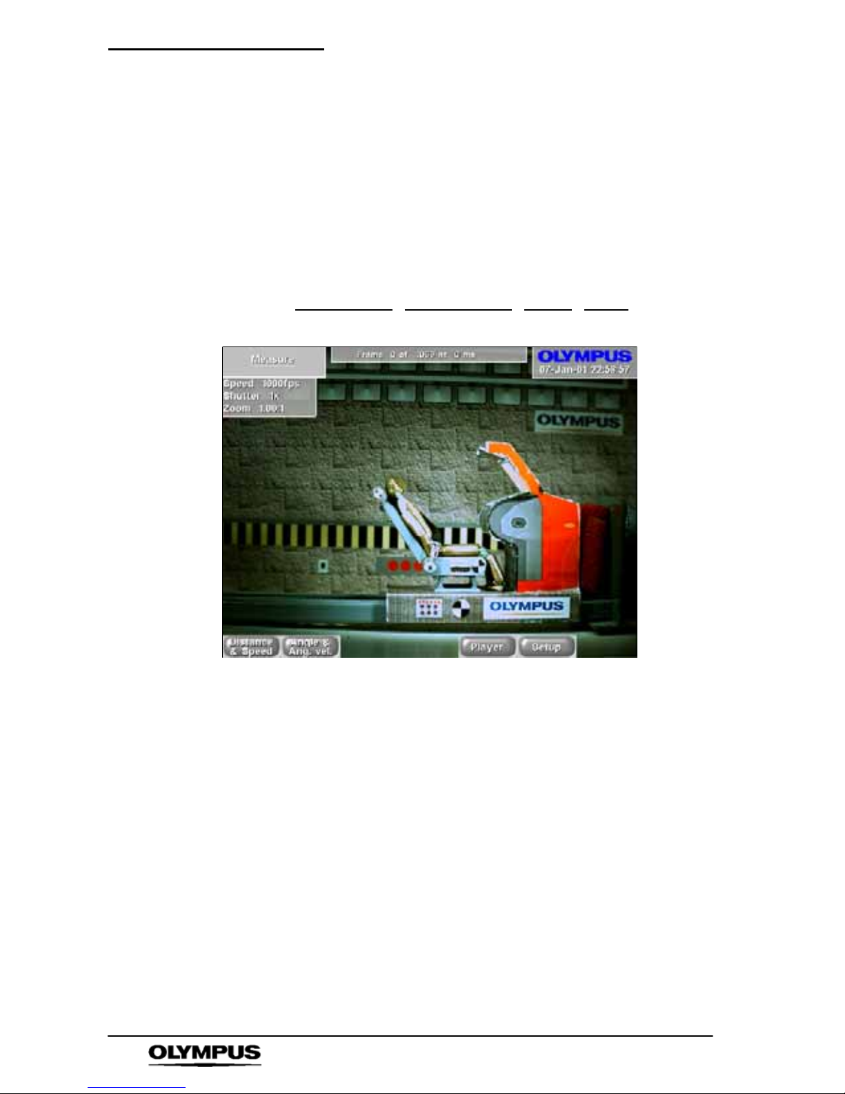
Software reference (CDU) i--SPEED 2
78
i--SPEED LT, i--SPEED 2
1. Measure Menu
This is the home or start--up screen of the measurement system.
Before the system is used, the Set up menu must be accessed to
set the units of measurement and to calibrate the system by
measuring an object of known dimensions.
Access: i-- SPEED 2 Home
' Playback ' Measure
i-- SPEED 2 Home
' Live ' Playback ' Measure
Options: Speed & Dist
Ang & Ang Vel Player Setup
S The CDU will display the playback image
Page 81
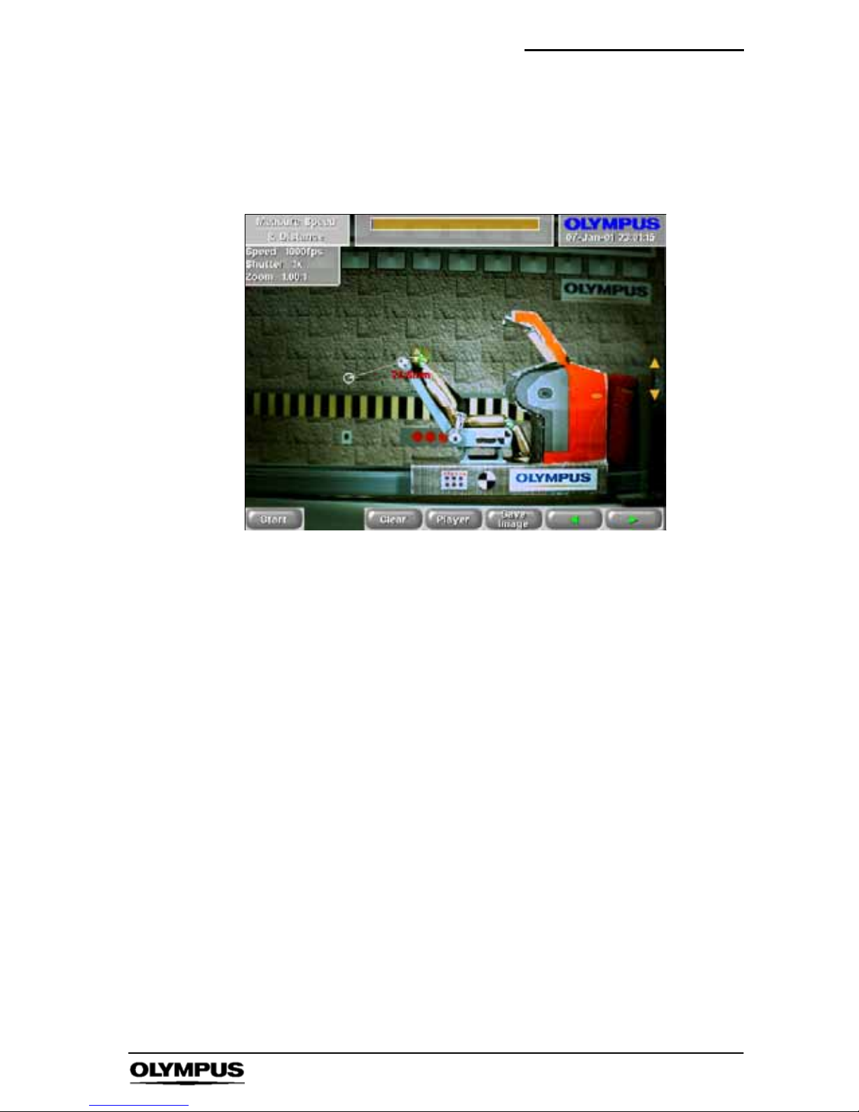
Software reference (CDU) i--SPEED 2
79
i--SPEED LT, i--SPEED 2
2. Measure Speed & Distance Menu
Access: Measure
' Measure Speed & Distance
Options: Start Clear Player Save Image
A"YB
S The CDU will display the playback image
` Start Control
This control marks the start of the measurement or calibration.
` Clear Control
This control clears all the currently marked points, to allow another
measurement to be taken. The control is disabled if there are no
marked points to clear.
` Player Control
The player is presented here to allow the measurement of speed
and angular velocity, by permitting the user to move to a different
frame for the end point of the measurement.
` Save Image
This control causes an image to be saved to the compact flash
card. After an image is saved, the Card Management menu
automatically appears. Pressing the Back button from the Card
Management menu will cause the CDU to return to the Measure
Speed & Distance Menu. The image will be saved as a bitmap,
without JPEG compression.
`
A " Y B
These controls allow the user to move the measurement cursor.
Page 82
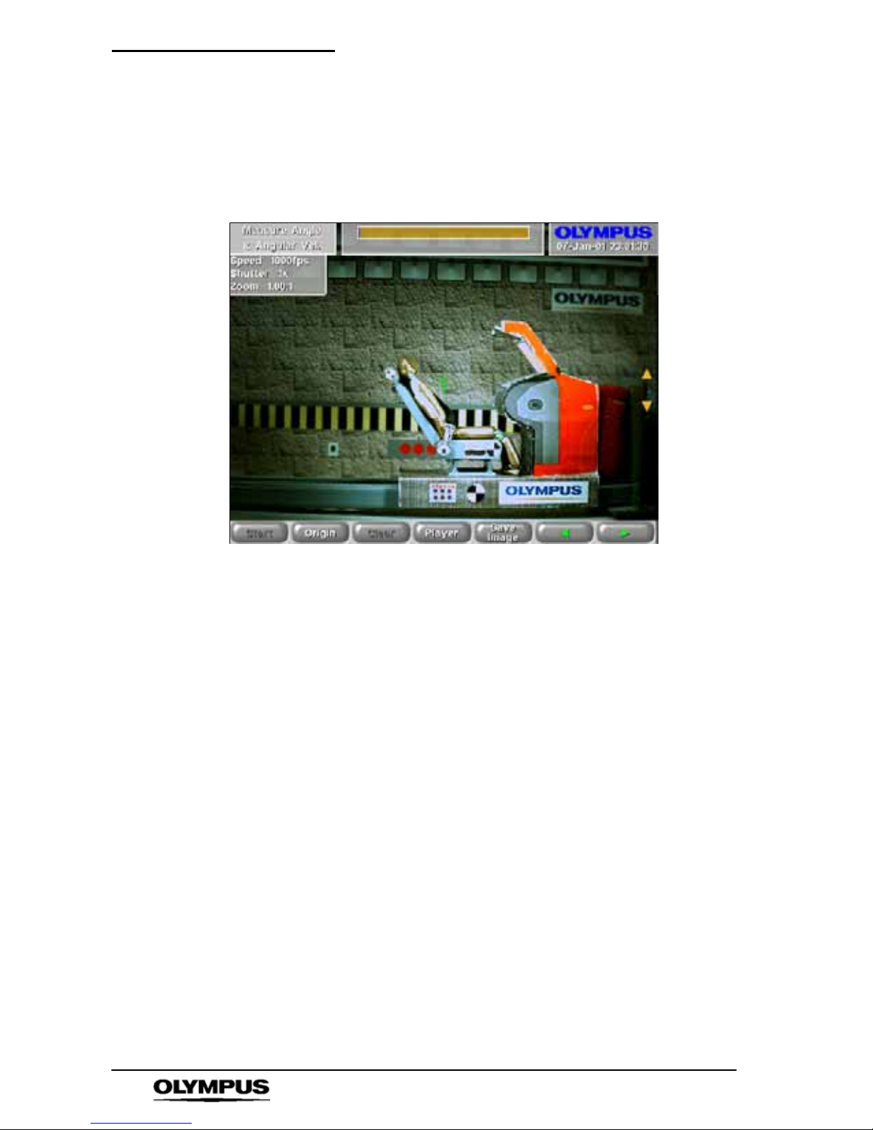
Software reference (CDU) i--SPEED 2
80
i--SPEED LT, i--SPEED 2
3. Measure Angular Velocity and Angle Menu
Access: Measure
' Measure Angular Velocity and Angle
Controls: Start Origin Clear Player Save Image
A"YB
S The CDU will display the playback image
` Start Control
This control marks the start of the measurement or calibration.
` Origin Control
This control marks the origin or axis of rotation for the
measurement of angle and angular velocity.
` Clear Control
This control clears all the currently marked points, to allow another
measurement to be taken. The control is disabled if there are no
marked points to clear.
`
A " Y B
These controls allow the user to move the measurement cursor.
Page 83
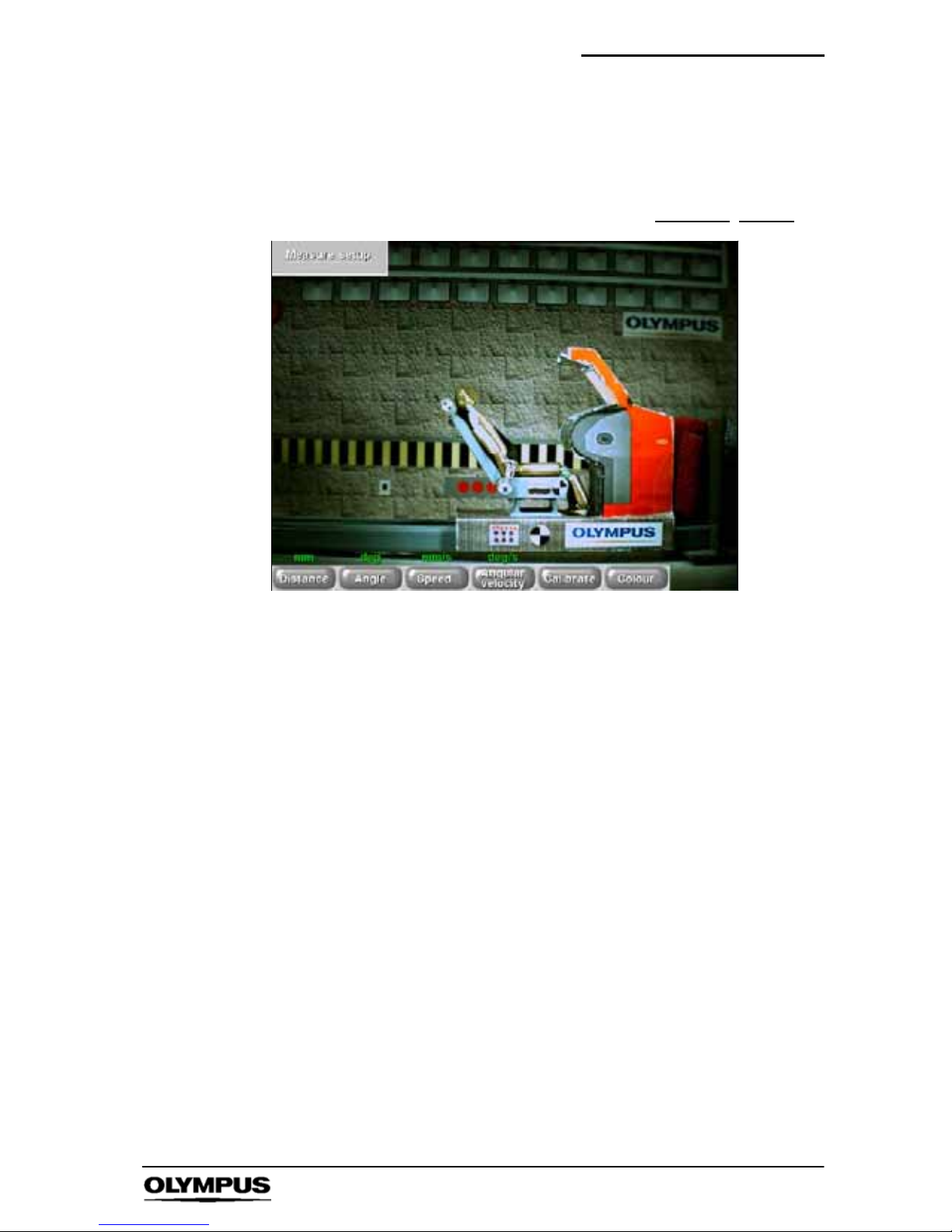
Software reference (CDU) i--SPEED 2
81
i--SPEED LT, i--SPEED 2
4. Measure Setup Menu
Access: Measure
' Measure Setup
Controls: Distance Angle Speed Ang Vel Calibrate
Colour
S The CDU will display the playback image
` Distance, Angle, Speed, Ang Vel Controls
These controls allow the user to choose the most appropriate units
for the measurement to be taken.
Page 84
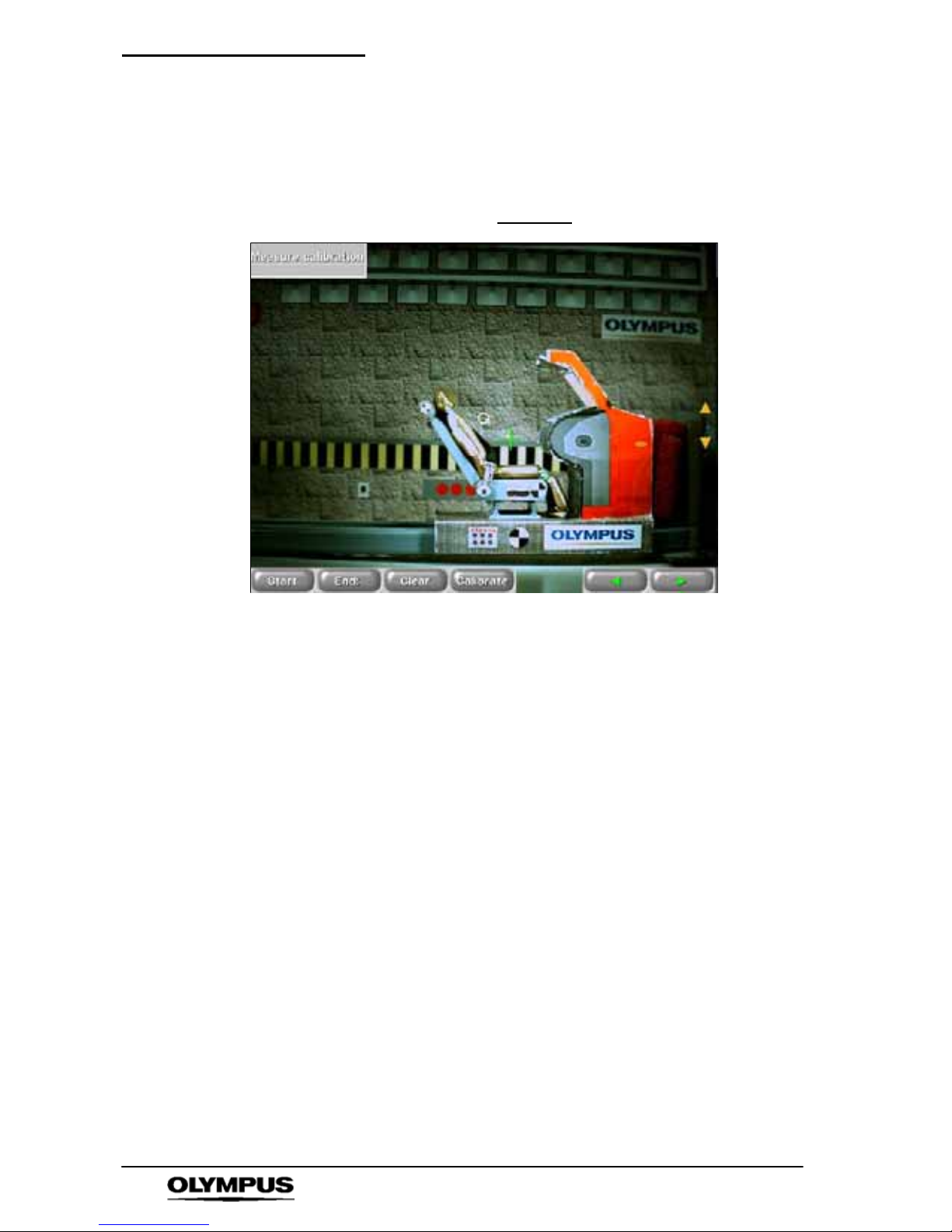
Software reference (CDU) i--SPEED 2
82
i--SPEED LT, i--SPEED 2
5. Measure Calibration Menu
Access: Measure
' Measure Setup ' Measure Calibrate
Controls: Start End Clear Calibrate
A"YB
S The CDU will display the playback image
` Start Control
This control marks the start of the measurement or calibration.
` End Control
This control marks the end of the known distance which is used in
the calibration process.
` Clear Control
This control clears all the currently marked points, to allow another
measurement to be taken. The control is disabled if there are no
marked points to clear.
`
A " Y B
These controls allow the user to move the measurement cursor.
Page 85
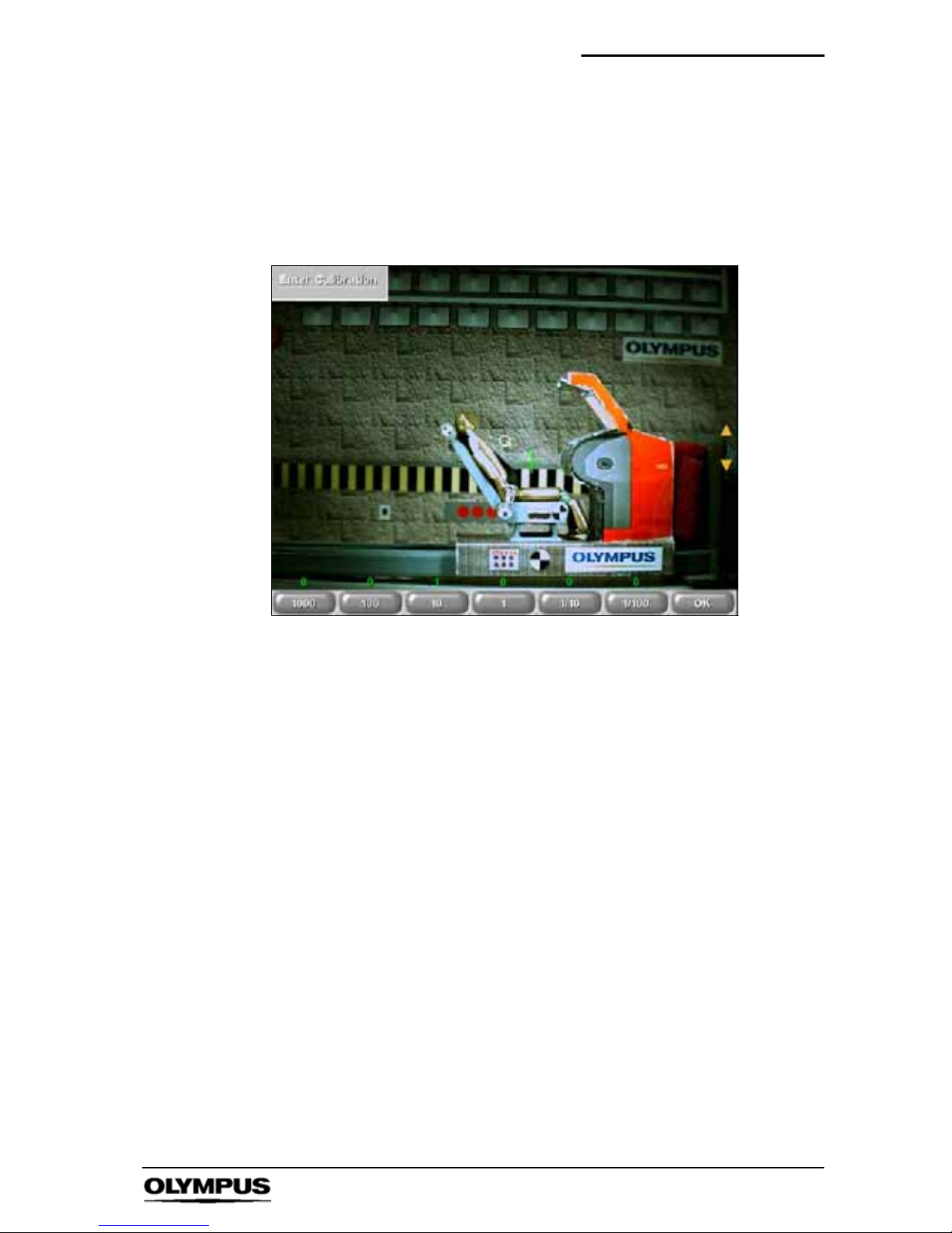
Software reference (CDU) i--SPEED 2
83
i--SPEED LT, i--SPEED 2
6. Enter Calibration Menu
Access: Measure
' Measure Setup
' Measure Calibrate ' Enter Calibration
Controls: 1000 100 10 1 0.1 0.01 OK
S The CDU will display the playback image
` Numerical Controls
In conjunction with the YBbuttons, these controls allow the entry
of the calibration value, which must be the accurately known
distance between the points just marked as “start” and “end”.
` OK Control
This control confirms the numerical entry just made and also
returns to the previous menu. This control is not available until
calibration value is non--zero.
Page 86
Software reference (CDU) i--SPEED 2
84
i--SPEED LT, i--SPEED 2
7. Colour Menu
Access: Measure
' Measure Setup ' Colour
Controls: Line Colour Text Colour
S The CDU will display the playback image
` Colour Controls
The colour controls are used to select the colours of the on-- screen
cursor and text to improve legibility against different backgrounds.
Page 87

Understanding ispeed
85
i--SPEED LT, i--SPEED 2
Chapter 8 Understanding the
Olympus i- SPEED LT &
i- SPEED 2
The Olympus i-- SPEED LT, i-- SPEED 2 has been designed with ease of
use in mind and all the functions of the c amera are accessed via clear and
descriptive menus. Every effort has been made to ensure that the menus
are intuitive.
High speed video however, is a complex subject in itself and several of the
functions of the Olympus i -- SPEED LT, i -- SPEED 2 are necessarily
complex. Reading the following section will provide the user with sufficient
knowledge of these areas to begin to understand the menus themselves.
A detailed description of the menus is given earlier.
` Speed, Resolution, Record Time, Economy Modes
In order for the Olympus i-- SPEED LT, i -- SPEED 2 to capture
frames of video at high speeds, a specialised sensor is used. In
spite of this, there is a limit to the number of pixels the sensor can
process per second, and this sets a limit on the frame speed of
1,000 frames per second (fps).
If faster operation is required, the number of pixels per frame must
be reduced, and this is accomplished by reducing the active area of
the sensor. This function is called windowing and can increase the
maximum frame speed of the Olympus i -- SPEED LT, i-- SPEED 2 to
33,000fps. The on--board zoom engine is used to automatically
compensate for the reduction in image size.
The camera contains electronic memory to hold the video images
as they are captured and this has a specific size, which is
dependent on the model chosen. The memory is therefore capable
of holding a fixed number of full resolution images and there is a
clearly defined maximum recording time at 1,000fps.
If the frame rate is reduced below 1,000fps, the available record
time will increase because the images are arriving less frequently.
If the frame rate is increased above 1,000fps, the available record
time will not change much because, although the images are
arriving more often, the image size is reduced and the two effects
tend to offset each other.
Page 88

Understanding ispeed
86
i--SPEED LT, i--SPEED 2
Under some circumstances, it is desirable to record for a longer
time than the memory permits. It will be noted however, that some
high speed events are primarily horizontal or vertical in nature and
so it is sometimes found that the edges of the screen contain no
useful video information. This fact is used by the economy modes,
which reduce the active area of the sensor below the size
suggested by the frame speed. This reduced image size increases
the number of images which may be stored in the memory and
thereby the record time is increased.
Several economy modes are available. Wide modes remove the
top and bottom edges of the image, tall modes remove the left and
right edges and square modes remove the top, bottom, left and
right edges of the image. In square mode, the internal zoom
engine is again used to compensate for the reduced image size.
There is a further trade--off associated with frame s peed and this is
discussed below.
` Shutter, Speed, Sensitivity
The sensor operates by capturing light, converting it to an
electronic facsimile of the optical image and supplying the memory
with the image while the cycle begins to repeat. The period during
which light is captured is called the “integration time”, “exposure
time” or “shutter time”. The shutter time is normally equal to the
maximum time available during the frame, called the “frame period”.
If the scene contains a very fast moving object, the object may
move an appreciable distance during the frame period and this will
cause the object to appear blurred. This “motion blur” is sometimes
undesirable, so the Olympus i-- SPEED LT, i-- SPEED 2 is able to
reduce the shutter time to a fraction of the frame period and this
causes the object to be “frozen” in each frame. The shutter time is
usually measured as the ratio between frame period and shutter
time, e.g. 10x means that the shutter is open for 1/10 of the frame
period.
Reducing the shutter time however, reduces the amount of time the
camera spends gathering light and the image will become dimmer.
For this reason, increasing the shutter setting will normally require
the addition of extra light to the scene.
A similar effect is found when the frame speed is increased. The
available shutter time is reduced because the frame period is
reduced -- the faster the frames are taken, the less time is spent on
each one. As a result of this, increasing frame speed will normally
require the addition of extra light to the scene.
Page 89

Understanding ispeed
87
i--SPEED LT, i--SPEED 2
` Dynamic Range
The human eye has an extraordinary ability to see dark and bright
objects simultaneously. The classical illustration of this is a plant
on a windowsill. The eye can see the plant and the view through
the window simultaneously. Ordinary video cameras are less
capable and can only produce images of one or the other. Either
the plant will be a featureless black silhouette and the view through
the window will be visible or the plant will be visible and the view
through the window will be a featureless white sheet.
The level of ability to see light and dark simultaneously is called
dynamic range.
The i -- SPEED LT, i-- SPEED 2 ’s image sensor is capable of
increasing its dynamic range by detecting light in a non--linear
fashion. This permits each pixel to individually reduce its sensitivity
with increasing light. This effect allows the sensor to gather image
features in very bright and dark areas simultaneously and this
process is known as “dynamic range extension”.
` Internal Memory, Circular buffer
When in record mode, the camera continuously stores frames in its
internal memory. That memory is configured in a circle so that,
once the memory is full, each new frame replaces the oldest stored
frame. In this way, the camera keeps a rolling history of the scene
it views and this process can continue indefinitely. This
configuration of the memory is called a “circular buffer”.
Once the desired event has occurred, the camera may be stopped
by pressing a menu button or raising a trigger event as discussed
below.
` Trigger
As mentioned above, the Olympus i -- SPEED LT, i -- SPEED 2
records video in a circular buffer and can do so indefinitely. At
some point, however, it is necessary to stop the recording process
in order to preserve the data in the memory.
The method of stopping the camera is highly important as it is this
which guarantees the capture of the event in question. There are
two methods of stopping the Olympus i -- SPEED LT, i-- SPEED 2 .
The first is a button press in the menu system and this immediately
stops the record process, so that the memory contains the history
prior to the button press.
Page 90

Understanding ispeed
88
i--SPEED LT, i--SPEED 2
The second method is to use an external electrical trigger, which
causes the camera to stop after a user--settable delay. By
permitting the camera to record for a brief time after the trigger,
some history before the trigger and also some future after the
trigger are preserved in the memory. In this way, the trigger may
occur in the middle of the event of interest and yet the camera can
still capture the whole event.
The delay between the trigger event and the cessation of recording
is controlled by a frame counter known as the trigger counter. The
length of this count is controlled by the menu system and is
expressed as a percentage of the total available record time of the
camera’s memory.
The counter value is described from the viewpoint of the final
recorded video clip, so that a setting of 0% sets the counter to
delay for the entire length of the circular buffer. In this way, the
trigger event will appear at the beginning of the video clip.
Similarly, a setting of 100% will cause the camera to stop
immediately a trigger is received, and this will place the trigger
event at the end of the recorded video clip.
Since the trigger is an electrical signal, the Olympus i -- SPEED LT,
i-- SPEED 2 may be set to wait for either the rising or the falling
edge of the trigger pulse.
The Olympus i-- SPEED LT, i-- SPEED 2 has two extensions to the
normal trigger operation described above. These are called
Record On Command (ROC) and Burst Record On Command
(BROC) and a description of these follows.
` ROC, BROC
Record On Command (ROC) and Burst Record On Command
(BROC) are extensions of the normal trigger function of the
Olympus i -- SPEED 2. Once Recording mode is selected in ROC
mode, the camera only records video into the memory while the
trigger signal is true (active low). By judicious use of the trigger
connection (e.g. dextrous use of the supplied trigger switch) the
camera may record several short bursts of video into the memory
buffer.
For the purposes of ROC and BROC, the memory is not treated as
a circle, but is regarded as a straight line with a defined start and
end. When the memory is full, no further recording is possible. A
progress indicator is provided.
A facility is provided to erase video bursts from the memory in case
an error is made in the use of the trigger switch. A further facility is
provided to erase the entire memory.
Page 91

Understanding ispeed
89
i--SPEED LT, i--SPEED 2
BROC is an extension of ROC, in that a trigger edge (rather than
an active level) will cause the camera to record video for a
pre--defined time. The length of time that the trigger signal is active
is ignored. This function is especially useful for unattended
operation when several short events are likely to occur. The burst
time is settable in the menu system.
` Sensor, FPN, FPN Calibration
The image sensor used in the Olympus i-- SPEED LT, i-- SPEED 2
camera is a CMOS chip and, like all CMOS imagers, it has the
property of introducing fixed pattern noise (FPN) onto the image.
Most HSVC manufacturers provide some form of correction to
remove the FPN and the Olympus i -- SPEED LT, i-- SPEED 2
provides a fully automatic off--chip calibration system which
operates in under a second.
This system includes a mechanical shutter which removes the
requirement for the user to manually cover the lens as is found on
less capable cameras. The shutter gives a characteristic click
sound when it operates.
NOTE
When using the i-- SPEED 2 HG, the lens must be
completely covered (eg with a lens cap) from power on
until the splash screen appears.
The system operates automatically on start--up and also after a few
moments of operation and this should normally be sufficient. Under
extreme circumstances, however, especially in high temperature
environments, the calibration system may need to be manually
operated some time after switch--on. This is indicated by the
presence of FPN on the image. FPN will give the image a gritty
appearance, almost as though the picture has been printed onto
sandpaper, and may also produce thin vertical stripes.
The control to manually trigger the calibration is found in the menu
system.
Page 92

Understanding ispeed
90
i--SPEED LT, i--SPEED 2
` White Balance
The human eye automatically adjusts its colour processing in order
to make white objects look “white” in spite of varying ambient
lighting colour. When viewing video on a monitor, however, the eye
judges white based on the ambient around the monitor, not on the
ambient around the camera. For this reason, a colour camera must
also adjust its processing to compensate for the ambient lighting
and configure its output to produce the electronic version of pure
white (red = green = blue) when a white object is viewed. In this
way, the camera can render white objects as white on the monitor,
in spite of ambient light coloration. This function is called white
balance.
The Olympus i-- SPEED LT, i-- SPEED 2 provides two types of white
balance, pre--set and automatic. Several pre --set white balance
settings are provided, based on light source technologies found in
the Olympus range of industrial light sources.
The automatic function relies on the user placing a pure white
reference (sheet of paper etc.) if front of the camera, completely
filling the field of view and then pressing the WB Set button. When
this is done, the camera will sample the reference and reconfigure
its processing electronics to render this as pure white. The
reference must not be removed until the white balance is complete,
so an on screen message shows the status of the white balance
process.
` Lighting
The Olympus i-- SPEED LT, i-- SPEED 2 has been designed to
remove most of the difficulty associated with taking high speed
video shots, but two areas of critical importance still remain, lenses
and lighting. In many cases, most of the time taken when working
with the Olympus i-- SPEED LT, i-- SPEED 2 will be used in setting
up the lighting, framing the shot and choosing the correct lens.
Earlier sections of this document have described how the shutter
time and speed setting of the camera dramatically increase the
requirement for light. The result of this is that most high speed
video applications require a large amount of lighting and this is a
common theme in the high speed video industry. As a rough guide,
most indoor shots require 500 to 2,000 watts of additional lighting.
This is traditionally provided by shining a few high power spot lights
on the target scene but, for smaller targets, the Olympus range of
industrial light sources and light guides provide ideal illumination.
Simply providing a large wattage of light is not suitable for most
applications. It is usually necessary to carefully focus and target
the light, so general purpose floodlights are not normally useful in
HSV work.
Page 93

Understanding ispeed
91
i--SPEED LT, i--SPEED 2
An illustration is given from the experience of the i-- SPEED LT,
i-- SPEED 2 development team. A car parts manufacturer wished to
view a rapid movement in the mechanism of a prototype seatbelt
reel. The scene was illuminated with several 1,000 watt garden
floodlights, but this was sufficient for only a few hundred frames per
second. The lighting was removed and replaced by a single
specialised 500 watt spotlight and this permitted operation at 1,000
fps. When faster operation was required, the s potlight was
augmented by an Olympus Industrial light source and liquid light
guide and this increased the operating speed to 4,000fps.
This example is included to show that the quantity of light is
significantly less important than the concentration of light. Olympus
representatives are able to supply specialised lighting which has
been selected to be suitable for most high speed video
applications.
` View Finder
In contrast with some inferior products, the Olympus i-- SPEED LT,
i-- SPEED 2 camera presents the live image on the CDU or monitor
screen at all possible times. Some menus do require the image to
be obscured and the splash screen logo is used for this purpose.
Also, the playback screen is used to display the contents of the
memory buffer, rather than a live image. During the live view and
the record process, however, the screen will display a live, colour,
real time image, updated at 60 frames per second.
` Lenses
The choice of lens can make a dramatic difference to the video
images obtained.
Choosing the lens must begin with the focal length, which is
expressed in mm. A lens with a large focal length would normally
be chosen when a small area is to be viewed or the camera is to be
a long distance away from the scene, because a longer focal length
means a greater magnification. This type of lens has the
disadvantage of reducing the apparent distance between objects
which are arranged axially with the camera. This is called
foreshortening. Lenses with long focal lengths also tend to have a
smaller maximum iris setting (higher f number) and are therefore
dimmer than long focal length lenses.
Page 94

Understanding ispeed
92
i--SPEED LT, i--SPEED 2
A lens with a s hort focal length is chosen when a wide area is to be
viewed, or the camera is to be placed near to the scene. Lenses
with a very short focal length have the disadvantage of distorting
the perspective of the image and this is called barrel distortion.
Normal lenses have a controllable iris or aperture. The iris controls
the amount of light available to the camera. The higher the f
number, the less light the lens transmits. Increasing the number by
1.4 times (e.g. from f/4 to f/5.6), is called 1 stop and halves the light
throughput.
There is a secondary effect of reducing the iris (increasing the f
number) and this is an increase in the depth of field. This means
that the lens is more able to focus on close and distant objects
simultaneously, so a small iris setting is advantageous.
This is in conflict with the normal HSV requirement for as much light
as possible, especially at high speeds and fast shutter times.
Probably the greatest art in lens set--up is striking a balance
between getting all objects in the scene into focus and having a
bright enough image. It is advisable in general to operate with a
smaller iris (higher f number) and add more light.
It is not possible to specify an ideal lens, because photography is
dependant on the object being photographed, but an “average”
lens for the Olympus i-- SPEED LT, i-- SPEED 2 would have a focal
length of 25mm and an iris range of f/1.4 to f/22.
When purchasing lenses for the Olympus i -- SPEED LT, i-- SPEED 2
it must be remembered that the CMOS imager is quite large in
size, so a 1” format (minimum) lens is required.
` Motion JPEG Compression (not MPEG)
The compressed movie format of the i-- SPEED LT, i-- SPEED 2 also
relies on JPEG compression and uses the M--JPEG format which is
used by QuickTim er and Microsoft Windowsr “.avi” files.
The most common compression technique for moving images is
MPEG, as is used in DVD and digital TV. The Olympus
i-- SPEED LT, i -- SPEED 2 does not use this format as it is not suitable
for high speed video. This is because MPEG relies not only on
compressing the image, but also compressing the motion, by only
saving the changes between frames. This is called inter--frame
compression and works by extracting the motion from the video and
estimat i ng its impact on the image. The decompressed video,
theref or e, is partly built on statistical estimat i on of motion. As a result
of this, many high speed video users find that the very thing they wish
to analyse -- motion -- is badly distorted by MPEG.
Page 95

Understanding ispeed
93
i--SPEED LT, i--SPEED 2
` JPEG Compression
Although the Olympus i -- SPEED LT, i -- SPEED 2 c ontains a
state--of--the --art microprocessor system, there are still limitations
on the speed with which data can be written to a Compact flash
card or an Ethernet channel. Even the most modern memory cards
have a limited capacity, and the amount of video that can be saved
in any one test session is often restricted.
In order to overcome these two issues, the Olympus i-- SPEED LT,
i-- SPEED 2 contains a piece of electronics called a JPEG
Compressor. This device can take live frames of video and
compress them from their raw “bitmap” format into a more tightly
compacted format called JPEG (named after the Joint Picture
Expert Group who invented the format and techniques involved)
The term “bitmap” means that for every pixel in the image, three
numbers are stored in the file, one each for red, green and blue. In
this way, every pixel is fully described and the storage of the image
is completely accurate to the original. On the other hand, this is
extremely wasteful. If this page were to be stored as a bitmap, the
file would contain a large amount of duplicated information,
because there is a large amount of pure flat white to be stored.
JPEG compression involves breaking the image into 8 x 8 or 16 x
16 pixel blocks and examining each block in turn to see if there is
any redundant information. Once this has been established, a
decision can be made about exactly what constitutes redundancy,
and so the compression ratio may be varied. (For the more
technical reader, this process is based on Discrete Cosine
Transformation followed by Huffman Encoding.)
Naturally, to achieve a higher compression ratio, some information
may be omitted, and although only the least relevant information is
omitted, some loss of image data does occur. This is normally
seen as faint speckles around highly detailed sharp edges in the
image. The higher the compression rate, the more loss occurs. As
a guideline, 7:1 compression produces images which are basically
indistinguishable from the original. 15:1 (the most common ratio for
digital cameras) produces losses which are only visible by
someone who is deliberately looking for artefacts under high zoom.
65:1 produces artefacts which are occasionally visible, but do not
detract from the appearance of the image.
Page 96

Maintenance
94
i--SPEED LT, i--SPEED 2
Chapter 9 Maintenance
9.1 Cleaning
To prevent electric shock or damage to equipment, always disconnect
from the power supply before attempting to clean.
Camera CMOS protective glass and CDU
screen
Clean using lens tissues moistened with a solvent solution
composed of 70% ether / 30% industrial methylated spirits.
DO NOT use hard or abrasive materials.
Camera cooling holes
Periodically inspect the camera cooling holes to ensure they are
not blocked with fluff, dirt etc. Clean as necessary.
General cleaning
Wipe equipment clean with a soft cloth dampened with a mild
detergent solution.
9.2 Storage and transportation
After use
Always pack the product in the kit case after use or for
transportation.
Padlock/Case strap
For security and to prevent inadvertent opening of the case during
transportation, it is recommended that the padlock is fitted and the
case strap is secured around the case.
9.3 Repair
The i -- SPEED LT, i-- SPEED 2 camera contains a user replaceable
fuse located in th
e rear panel. There are no other user repairable
components.
Page 97
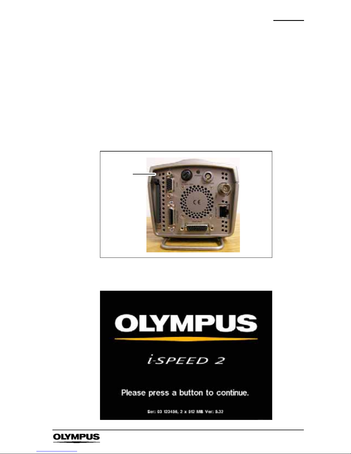
Maintenance
95
i--SPEED LT, i--SPEED 2
9.4 Soft reset
The i -- SPEED LT, i-- SPEED 2 has been designed for use in
industrial applications and has been tested to meet internationally
recognised standards, but in the unlikely event that the camera
stops responding it can be restarted using the soft rest facility. This
will enable access to a data recovery menu; which allows any video
stored on the cameras internal memory to be saved to a compact
flash card.
To operate the soft rest push a pin through the access hole in the
rear panel of the camera.
Soft reset
switch
After a few seconds the cameras internal FPN shutter will operate
and the i--SPEED 2 splash screen will appear.
Page 98
Maintenance
96
i--SPEED LT, i--SPEED 2
Press any button to access the data recovery menu.
Data recovery menu -- CDU
Speed and economy mode will need to be reset, before s electing
the player or clip select options.
The data recovery menu gives access to the cameras entire
memory independent of how long the camera was recording. This
means that some of the memory may contain invalid data or
previously recorded video.
9.5 Camera Software Upgrade
Periodically Olympus will issue new versions of camera software.
The following procedure should be adopted when installing these
upgrades.
1. Power up the camera and note its current software version
number, located in the bottom left hand corner of the splash
screen.
2. Copy the new software file to an empty compact flash card. The
file name of the software upgrade will take the following format:
Page 99

Maintenance
97
i--SPEED LT, i--SPEED 2
V X -- XX . Bin
a b c d
a. Version
b. Major software issue number
c. Minor software issue number
d. File extension
3. Insert the compact flash card into the slot on the rear of the
camera. A message will appear asking for confirmation to begin
the software upgrade process.
4. During the upgrade process the following messages will be
displayed:
Erasing Flash
Programming Flash
Programming complete
5. Once the “Programming complete” message appears turn the
camera off and on again. The new software version number will
appear on the splash screen
Page 100

Spares & Accessories
98
i--SPEED LT, i--SPEED 2
Chapter 10 Spares and Accessories
Spares
Part No.
Power Supply 12V DC universal input ........................ K7505046
MainsCable--UK ......................................... 7145454
MainsCable--Europe...................................... 7145462
MainsCable--USA ........................................ 7318375
Instructions (English) ...................................... K10000151
Camerafuse(packof5) .................................... 7502254
ControllerCable,3m ....................................... K7504982
Ethernetcable ............................................ K3921618
Ethernetcrossovercable ................................... K3921651
Compositevideocable ..................................... 3104737
Feature Connector Cable ................................... K10003827
Trigger Switch ............................................. K7505051
PCMCIA Compact Flash Adapter ............................ K7505053
TransitCasewithOuterSleeve .............................. K10003716
CombinationPadlock ...................................... K3921567
Internal memory upgrade from 2GB to 4GB .................... K7505069
Casestrap................................................ K3931429
 Loading...