

Page 1

HSMT-Compact
Manual Weld Scanner
User’s Manual
DMTA017-01EN — Rev. F
August 2016
This instruction manual contains essential information on how to use this Olympus product safely and effectively.
Before using this product, thoroughly review this instruction manual. Use the product as instructed.
Keep this instruction manual in a safe, accessible location.
Page 2

Olympus Scientific Solutions Americas, 48 Woerd Avenue, Waltham, MA 02453, USA
Copyright © 2007, 2012, 2013, 2014, 2016 by Olympus. All rights reserved. No part of this
publication may be reproduced, translated, or distributed without the express written
permission of Olympus.
This document was prepared with particular attention to usage to ensure the accuracy of the
information contained therein, and corresponds to the version of the product manufactured
prior to the date appearing on the title page. There could, however, be some differences
between the manual and the product if the product was modified thereafter.
The information contained in this document is subject to change without notice.
Part number: DMTA017-01EN
Rev. F
August 2016
Printed in Canada
All brands are trademarks or registered trademarks of their respective owners and third
party entities.
Page 3

DMTA017-01EN, Rev. F, August 2016
Table of Contents
List of Abbreviations ........................................................................................ v
Labels and Symbols ........................................................................................... 1
Important Information — Please Read Before Use ..................................... 3
Intended Use .......................................................................................................................... 3
Instruction Manual ................................................................................................................ 3
Equipment Compatibility ..................................................................................................... 4
Presence of Visual Interferences or Phantom Spots ......................................................... 5
Repair and Modification ....................................................................................................... 5
Safety Symbols ....................................................................................................................... 5
Safety Signal Words ............................................................................................................... 6
Note Signal Words ................................................................................................................. 7
Safety ....................................................................................................................................... 7
Warnings ................................................................................................................................. 8
Equipment Disposal .............................................................................................................. 8
CE (European Community) ................................................................................................. 8
WEEE Directive ...................................................................................................................... 9
Warranty Information ........................................................................................................... 9
Technical Support ................................................................................................................ 10
Introduction ...................................................................................................... 11
1. Overview ..................................................................................................... 13
2. Scanner Assembly and Setup .................................................................. 19
2.1 Changing the Frame Configuration ....................................................................... 19
2.2 Attaching the Umbilical Cable ................................................................................ 23
2.3 Setting Up the Scanner ............................................................................................. 25
Table of Contents iii
Page 4

DMTA017-01EN, Rev. F, August 2016
3. Operating the Scanner .............................................................................. 27
4. Maintenance ................................................................................................ 29
4.1 Replacing Wheels ...................................................................................................... 29
4.2 Replacing a Conventional Ultrasonic Probe ......................................................... 30
4.3 Replacing a Phased Array Probe ............................................................................ 33
4.4 Unit Cleaning ............................................................................................................. 35
5. Specifications .............................................................................................. 37
6. Accessories and Spare Parts ..................................................................... 41
6.1 Umbilical Cables ....................................................................................................... 41
6.2 Yokes ........................................................................................................................... 42
6.3 Couplant-Feed Units ................................................................................................ 43
6.4 Connector Reference ................................................................................................. 44
6.5 Spare Parts .................................................................................................................. 44
List of Figures ................................................................................................... 49
List of Tables ..................................................................................................... 51
Index ................................................................................................................... 53
Table of Contents
iv
Page 5

List of Abbreviations
hex hexagonal
ID inside diameter
PA phased array
SLA spring-loaded arm
TOFD time-of-flight diffraction
DMTA017-01EN, Rev. F, August 2016
List of Abbreviations
v
Page 6

DMTA017-01EN, Rev. F, August 2016
List of Abbreviations
vi
Page 7

DMTA017-01EN, Rev. F, August 2016
Model number
Serial number
Labels and Symbols
Product information and safety-related labels (with symbols) are attached to the
HSMT-Compact scanner at the locations shown in Figure i-1 on page 1 and Figure i-2
on page 2. Label details are provided in Table 1 on page 2. If any or all of the labels or
symbols are missing or illegible, please contact Olympus.
Figure i‑1 Identification label location
Labels and Symbols
1
Page 8

DMTA017-01EN, Rev. F, August 2016
Rating label (see
Table 1 on page 2)
Figure i‑2 Rating label location
Table 1 Rating label content
Content
Labels and Symbols
2
S/N
The serial number is an eight (8) digit number
The CE marking is a declaration that this product conforms to
all the applicable directives of the European Community. See
the Declaration of Conformity for details. Contact your Olympus
representative for more information.
The regulatory compliance mark (RCM) label indicates that
the product complies with all applicable standards, and has
been registered with the Australian Communications and
Media Authority (ACMA) for placement on the Australian
market.
The WEEE symbol indicates that the product must not be
disposed of as unsorted municipal waste, but should be
collected separately.
The direct current symbol.
Page 9

DMTA017-01EN, Rev. F, August 2016
WARNING
Important Information — Please Read Before Use
Intended Use
The HSMT-Compact scanner is designed to perform nondestructive inspections on
industrial and commercial materials.
Do not use the HSMT-Compact scanner for any purpose other than its intended use. It
must never be used to inspect or examine human or animal body parts.
Instruction Manual
This instruction manual contains essential information on how to use this Olympus
product safely and effectively. Before using this product, thoroughly review this
instruction manual. Use the product as instructed.
Keep this instruction manual in a safe, accessible location.
Important Information — Please Read Before Use
3
Page 10

DMTA017-01EN, Rev. F, August 2016
IMPORTANT
CAUTION
Some of the details of components and/or software images in this manual may differ
from your instrument’s components or software display. However, the principles
remain the same.
Equipment Compatibility
The HSMT-Compact scanner is compatible with the Olympus ancillary equipment
listed in Table 2 on page 4.
Always use equipment and accessories that meet Olympus specifications. Using
incompatible equipment could cause equipment malfunction and/or damage, or
human injury.
Important Information — Please Read Before Use
4
Table 2 Ancillary equipment
Equipment Description
OmniScan PA and FOCUS Several types of phased array instrument
model can be used (may require one of the
encoder cable adaptors listed below).
Phased array probe and wedge Several models used. See Table 7 on page 42
for optional holder models required according
to wedge models.
P/N: U8775201 Scanner interface adaptor to connect scanner
encoder cables with DE15 connector to
OmniScan MX2, SX or FOCUS PX with LEMO
connector scanner interface.
P/N: U8780329 Scanner interface adaptor to connect scanner
encoder cables with LEMO connector to
OmniScan MX with DE15 connector scanner
interface.
Page 11
DMTA017-01EN, Rev. F, August 2016
CAUTION
Table 2 Ancillary equipment (continued)
Equipment Description
P/N: U8769010 0.3 m long adaptor LEMO female to Bendix
male linking LEMO encoder cable to Focus LT
P/N: U8767107 0.3 m long adaptor DE15 female to Bendix
male linking DE15 encoder cable to Focus LT
Presence of Visual Interferences or Phantom Spots
In a situation of physical proximity to powerful electromagnetic radiators, visual
interferences or phantom spots may be present. These interferences are temporary
and their persistence is not permanent in comparison with physical features of the
inspected part.
Repair and Modification
The HSMT-Compact scanner does not contain any user-serviceable parts. Opening
the instrument might void the warranty.
In order to prevent human injury and/or equipment damage, do not disassemble,
modify, or attempt to repair the instrument.
Safety Symbols
The following safety symbols might appear on the instrument and in the instruction
manual:
Important Information — Please Read Before Use
5
Page 12
DMTA017-01EN, Rev. F, August 2016
DANGER
WARNING
General warning symbol
This symbol is used to alert the user to potential hazards. All safety messages that
follow this symbol shall be obeyed to avoid possible harm or material damage.
Shock hazard caution symbol
This symbol is used to alert the user to potential electric shock hazards. All safety
messages that follow this symbol shall be obeyed to avoid possible harm.
Magnetic field warning symbol
This symbol is used to alert the user to potentially strong magnetic fields. All
safety messages that follow this symbol shall be obeyed to avoid possible harm.
Safety Signal Words
The following safety symbols might appear in the documentation of the instrument:
The DANGER signal word indicates an imminently hazardous situation. It calls
attention to a procedure, practice, or the like that if not correctly performed or
adhered to will result in death or serious personal injury. Do not proceed beyond a
DANGER signal word until the indicated conditions are fully understood and met.
The WARNING signal word indicates a potentially hazardous situation. It calls
attention to a procedure, practice, or the like that if not correctly performed or
adhered to could result in death or serious personal injury. Do not proceed beyond a
WARNING signal word until the indicated conditions are fully understood and met.
Important Information — Please Read Before Use
6
Page 13

DMTA017-01EN, Rev. F, August 2016
CAUTION
IMPORTANT
NOTE
TIP
The CAUTION signal word indicates a potentially hazardous situation. It calls
attention to a procedure, practice, or the like that if not correctly performed or
adhered to may result in minor or moderate personal injury, material damage,
particularly to the product, destruction of part or all of the product, or loss of data. Do
not proceed beyond a CAUTION signal word until the indicated conditions are fully
understood and met.
Note Signal Words
The following safety symbols could appear in the documentation of the instrument:
The IMPORTANT signal word calls attention to a note that provides important
information, or information essential to the completion of a task.
The NOTE signal word calls attention to an operating procedure, practice, or the like,
which requires special attention. A note also denotes related parenthetical
information that is useful, but not imperative.
The TIP signal word calls attention to a type of note that helps you apply the
techniques and procedures described in the manual to your specific needs, or
provides hints on how to effectively use the capabilities of the product.
Safety
Before turning on the instrument, verify that the correct safety precautions have been
taken (see the following warnings). In addition, note the external markings on the
instrument, which are described under “Safety Symbols” on page 5.
Important Information — Please Read Before Use
7
Page 14

DMTA017-01EN, Rev. F, August 2016
WARNING
Warnings
General Warnings
• Carefully read the instructions contained in this instruction manual prior to
turning on the instrument.
• Keep this instruction manual in a safe place for further reference.
• Follow the installation and operation procedures.
• It is imperative to respect the safety warnings on the instrument and in this
instruction manual.
• If the equipment is used in a manner not specified by the manufacturer, the
protection provided by the equipment could be impaired.
• Do not install substitute parts or perform any unauthorized modification to the
instrument.
• Service instructions, when applicable, are for trained service personnel. To avoid
the risk of electric shock, do not perform any work on the instrument unless
qualified to do so. For any problem or question regarding this instrument, contact
Olympus or an authorized Olympus representative.
• Do not allow metallic or foreign objects to enter the device through connectors or
any other openings. Otherwise, a malfunction or electric shock may result.
Equipment Disposal
Before disposing of the HSMT-Compact scanner, check your local laws, rules, and
regulations, and follow them accordingly.
CE (European Community)
This device complies with the requirements of both directive
2014/30/EU concerning electromagnetic compatibility and directive
2014/35/EC concerning low voltage. The CE marking indicates
compliance with the above directives.
Important Information — Please Read Before Use
8
Page 15

DMTA017-01EN, Rev. F, August 2016
WEEE Directive
In accordance with European Directive 2012/19/EU on Waste Electrical
and Electronic Equipment (WEEE), this symbol indicates that the
product must not be disposed of as unsorted municipal waste, but
should be collected separately. Refer to your local Olympus distributor
for return and/or collection systems available in your country.
Warranty Information
Olympus guarantees your Olympus product to be free from defects in materials and
workmanship for a specific period, and in accordance with conditions specified in the
Olympus Scientific Solutions Americas Inc. Terms and Conditions available at
http://www.olympus-ims.com/en/terms/.
The Olympus warranty only covers equipment that has been used in a proper
manner, as described in this instruction manual, and that has not been subjected to
excessive abuse, attempted unauthorized repair, or modification.
Inspect materials thoroughly on receipt for evidence of external or internal damage
that might have occurred during shipment. Immediately notify the carrier making the
delivery of any damage, because the carrier is normally liable for damage during
shipment. Retain packing materials, waybills, and other shipping documentation
needed in order to file a damage claim. After notifying the carrier, contact Olympus
for assistance with the damage claim and equipment replacement, if necessary.
This instruction manual explains the proper operation of your Olympus product. The
information contained herein is intended solely as a teaching aid, and shall not be
used in any particular application without independent testing and/or verification by
the operator or the supervisor. Such independent verification of procedures becomes
increasingly important as the criticality of the application increases. For this reason,
Olympus makes no warranty, expressed or implied, that the techniques, examples, or
procedures described herein are consistent with industry standards, nor that they
meet the requirements of any particular application.
Olympus reserves the right to modify any product without incurring the
responsibility for modifying previously manufactured products.
Important Information — Please Read Before Use
9
Page 16

DMTA017-01EN, Rev. F, August 2016
Technical Support
Olympus is firmly committed to providing the highest level of customer service and
product support. If you experience any difficulties when using our product, or if it
fails to operate as described in the documentation, first consult the user’s manual, and
then, if you are still in need of assistance, contact our After-Sales Service. To locate the
nearest service center, visit the Service Centers page at: http://www.olympusims.com.
Important Information — Please Read Before Use
10
Page 17

DMTA017-01EN, Rev. F, August 2016
Introduction
This manual provides instructions for assembling, installing, and operating the
HSMT-Compact scanner. The HSMT-Compact scanner is a versatile pipe and plate
scanner that can be used to inspect pipes of 4 in. schedule or greater (with minimum
outside diameters of 114 mm [or 4.5 in.]), as well as flat surfaces.
To help users understand the HSMT-Compact scanner’s operation and configuration,
this manual provides the following subject matter:
• The scanner’s main components
• Assembly and setup
• Scanner operation
•Maintenance
• Technical specifications, including system connectors
• Accessories and spare parts, with exploded view diagram and descriptions
Introduction 11
Page 18

DMTA017-01EN, Rev. F, August 2016
12
Introduction
Page 19
DMTA017-01EN, Rev. F, August 2016
1. Overview
This chapter provides an overview of the main HSMT-Compact scanner components.
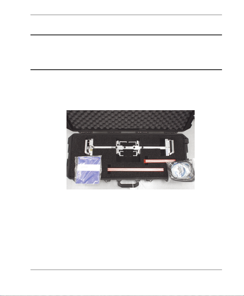
The contents of a standard case are shown in Figure 1-1 on page 13.
Figure 1‑1 Case contents
The main HSMT-Compact scanner components are the frame (with four wheels and
two handles), the probe holders, the water-couplant distribution system, and the
encoder (see Figure 1-2 on page 14).
Overview 13
Page 20

DMTA017-01EN, Rev. F, August 2016
Water manifold
Handle for moving the
scanner (2)
Magnetic wheels
Safety
attachment ring
or umbilical
bracket
Encoder Frame
Water feed
Probe holder (2)
14
Figure 1‑2 The HSMT‑Compact scanner
Frame
The frame provides a base for up to four conventional ultrasonic probes or
phased array ultrasonic probes. It is supported at both ends by subassemblies that
hold the wheels and handles used to move the unit across the surface being
inspected. If necessary, the handles can be removed to reduce the height of the
scanner.
Magnetic wheels
The magnetic wheels help hold the unit against a ferromagnetic inspection
surface. The wheels are covered with a plastic layer for smooth motion during
inspection (see Figure 1-2 on page 14).
Chapter 1
Page 21

DMTA017-01EN, Rev. F, August 2016
WARNING
To avoid injury, use caution when handling the magnetic wheels; the magnetic pull of
the wheels is strong and could cause bodily harm—for example, a finger pinched
between two wheels, or between a wheel and a steel surface.
Probe holders
The probe holders are used to secure the probes. The probe-holder position is
adjustable. The probe holders are also spring-loaded to ensure a proper contact
between the probes and the surface to be inspected.
Wat e r manifold
Four tubes branch out from one main water-entry point to supply the wedges
with water couplant.
Encoder
A wheel encoder measures the scanner displacement to determine the position on
the scan axis.
The encoder is waterproof and compatible with the OmniScan unit. The encoder
is also spring-loaded to ensure that it remains in contact with the inspection
surface, with adequate pressure for different pipe diameters.
Safety attachment ring
This ring can be used to secure the scanner with a safety hook (see Figure 1-3 on
page 16). If the scanner is equipped with an umbilical cable, this cable can be
attached to the ring to prevent overtensioning of the probe cables.
Umbilical bracket
An umbilical bracket is supplied with the scanner for quick attachment of a cable
bundle wrapped with a divisible shell (see “Attaching the Umbilical Cable” on
page 23).
Overview 15
Page 22

DMTA017-01EN, Rev. F, August 2016
Main water-supply
tube
Safety attachment
ring or umbilical
bracket
Encoder-cable
connection
Water distribution
to wedges
Probe cables
Wheel encoder
Positioning a probe holder
Two removable rulers are provided on the top of the scanner frame to help
accurately position a probe holder. The edges of the probe-holder brackets can be
used to position the exit points of the ST1 and ST2 TOFD wedges, which are
designed to align with each other (see Figure 1-4 on page 17).
Figure 1‑3 Detail of connections
16
Chapter 1
Page 23

DMTA017-01EN, Rev. F, August 2016
Two removable rulers
The edges on the probe-holder brackets
Figure 1‑4 Removable rulers
Alternative frame configuration
The frame can hold both conventional ultrasonic probes and phased array
ultrasonic probes.
The frame section between the wheels can be changed to vary the scanner length
(see Figure 1-5 on page 17).
Figure 1‑5 Changing the scanner length
Overview 17
Page 24

DMTA017-01EN, Rev. F, August 2016
Preamplifier (optional)
Sliding the wheel assembly to change the frame
configuration
When loosened, the wheel assembly slides freely on the frame, and can be
temporarily removed and reinstalled in a different configuration. For example,
the frame can be positioned to extend outside the limits of the wheels, which is
well-suited to hard-to-reach areas, such as pipe-to-component welds (see
Figure 1-6 on page 18).
Preamplifier
If necessary, a preamplifier (often required for TOFD inspections) can be mounted
on the frame. In the example shown in Figure 1-6 on page 18, an Olympus
TRPP 5810 pulser/preamplifier is used. A bracket is required to mount the
TRPP 5810 on HSMT scanners. This bracket is included with some TRPP 5810
packages, and can also be ordered separately (part number: HSMT-A-BRK5810
[U8779088]).
Chapter 1
18
Figure 1‑6 Alternative scanner configuration
Page 25

DMTA017-01EN, Rev. F, August 2016
2. Scanner Assembly and Setup
This chapter explains how to adjust parts on the HSMT-Compact scanner (for
example, the wheel-assembly position on the frame), and how to set up the scanner
for inspection.
2.1 Changing the Frame Configuration
The frame configuration can be changed as follows:
• The frame section between the wheels can be changed to increase or decrease the
distance between the wheels. This is accomplished using frame sections of
different lengths.
OR
• The wheel-assembly position can be adjusted on the frame; it can be loosened and
moved along the frame section. As such, the wheel assembly can be temporarily
removed, and then reinstalled so that the frame and the probe extend outside the
limits of the wheels, which is ideal for hard-to-reach areas, such as pipe-tocomponent welds (see Figure 1-6 on page 18).
To change the frame section between the wheels
1. On the end of the scanner displaying the company name, perform the following
steps:
a) Using a hexagonal key, remove the two screws that attach the frame section to
the wheel assembly (see Figure 2-1 on page 20).
b) Remove the wheel assembly from the frame.
c) To facilitate reassembly, remove the T-nut, and then install it onto the new
frame section.
Scanner Assembly and Setup 19
Page 26

DMTA017-01EN, Rev. F, August 2016
Frame section
Wheel
assembly
Encoder
assembly
Thumb screw
Figure 2‑1 Sliding the wheel assembly off
2. On the water-manifold end of the scanner:
a) Remove the cable from the encoder assembly.
b) Remove the thumb screw that holds the encoder assembly, and then pull this
assembly away from the scanner (see Figure 2-2 on page 20).
The remaining frame screws are now easy to access.
20
Chapter 2
Figure 2‑2 Thumb screw for the encoder assembly
Page 27

DMTA017-01EN, Rev. F, August 2016
Frame section
Wheel
assembly
3. Using a hexagonal key, remove all five of the frame screws, and then pull out the
frame section (see Figure 2-3 on page 21).
Figure 2‑3 Removal of the frame screws behind the encoder assembly
4. Reinstall the new frame section and scanner parts in the reverse order from the
preceding steps.
To adjust the wheel-assembly position on the frame
1. Using a hexagonal key, loosen the two screws that hold the wheel assembly onto
the frame section (see Figure 2-4 on page 21).
Figure 2‑4 Loosening the wheel assembly
Scanner Assembly and Setup 21
Page 28

DMTA017-01EN, Rev. F, August 2016
NOTE
2. Slide the wheel assembly to the desired new location (see Figure 2-5 on page 22).
Figure 2‑5 Sliding the wheel assembly onto the frame
If necessary, you can temporarily remove the entire wheel assembly, and probe
holders from the frame section in order to reassemble them in the desired new
configuration.
3. Attach the remaining scanner components in the desired configuration. An
example inspection setup with the frame extended beyond the wheel limits is
shown in Figure 2-6 on page 23.
Chapter 2
22
Page 29

Figure 2‑6 Scanner with frame extended beyond wheel limits
2.2 Attaching the Umbilical Cable
DMTA017-01EN, Rev. F, August 2016
The umbilical cable can be attached to the HSMT-Compact scanner using the
umbilical bracket (see Figure 2-7 on page 24).
Scanner Assembly and Setup 23
Page 30

DMTA017-01EN, Rev. F, August 2016
Attachment
Umbilical bracket
Locking pin
Mounting hole
Figure 2‑7 Umbilical‑cable attachment and bracket
To attach the umbilical cable
1. Press the locking pin on the umbilical bracket, slide the mounting hole over the
attachment on the HSMT-Compact scanner, and then release the pin (see
Figure 2-8 on page 24).
24
2. Loosen the strap, wrap it around the umbilical cable, then reinsert the strap into
the buckle and tighten it (see Figure 2-9 on page 25).
Chapter 2
Figure 2‑8 AEIX378 umbilical‑cable attachment
Page 31

DMTA017-01EN, Rev. F, August 2016
Water-
manifold
intake
Encoder
connector
Short section of
tube between the
two unused watermanifold outlets
Water-manifold
outlets
Figure 2‑9 Loosened strap (left) and tightened strap (right)
2.3 Setting Up the Scanner
This section describes the procedure for preparing the HSMT-Compact scanner for
inspection.
To set up the scanner
1. Connect the probes and any other equipment (a preamplifier, for example) to the
acquisition unit.
2. Connect the encoder cable to the side of the scanner (carefully align the marks on
the connector), and then connect the other end of the encoder cable to the
instrument (see Figure 2-10 on page 25).
Figure 2‑10 Scanner connections
Scanner Assembly and Setup 25
Page 32

DMTA017-01EN, Rev. F, August 2016
Thumb screw
Bracket edge
TIP
NOTE
3. Connect the water-manifold intake to the feed system (see Figure 2-10 on
page 25).
4. Connect the water-manifold outlet to the wedge-couplant intake.
If only two out of the four water-manifold outlets are used, connect a tube
between the two unused outlets (see Figure 2-10 on page 25).
5. Adjust the probe position as follows:
a) Loosen the thumb screw that secures the probe-holder bracket to the scanner
frame (see Figure 2-11 on page 26).
26
Figure 2‑11 Adjusting the probe position
b) Slide the probe holder to the desired position, and then tighten the thumb
screw.
For the TOFD ST1 and ST2 models exclusively, the edges of the probe-holder brackets
are in line with the beam exit point of the wedge to facilitate probe positioning.
Equipment connections and probe positions vary according to the application. To
mount the components, you might have to add or correctly position T-nuts in the
frame slots.
Chapter 2
Page 33

DMTA017-01EN, Rev. F, August 2016
3. Operating the Scanner
The HSMT-Compact scanner is designed for manual use, and is straightforward to
operate.
To operate the scanner
1. Hold the scanner above the inspection surface, and then align the scanner so that
the inspection area is centered between the probes.
2. With the inspection area centered between the probes, bring the scanner’s
magnetic wheels into contact with the inspection surface.
3. Next, push or pull the scanner in the desired inspection direction.
If the inspection surface is made of a ferromagnetic material, the scanner does not
need to be pushed down to prevent liftoff.
Operating the Scanner 27
Page 34

DMTA017-01EN, Rev. F, August 2016
28
Chapter 3
Page 35

DMTA017-01EN, Rev. F, August 2016
WARNING
4. Maintenance
This chapter contains procedures for replacing wheels, probes, and wedges for both
conventional ultrasonic and phased array ultrasonic technologies. The probes may
need to be replaced if they malfunction, or if the inspection application has changed.
Depending on operating conditions, the HSMT-Compact scanner parts might need
periodic cleaning.
4.1 Replacing Wheels
This section contains the procedure for changing the wheels once they are too worn.
To replace wheels
To avoid injury, use caution when handling the magnetic wheels; the magnetic pull of
the wheels is strong and could cause bodily harm—for example, a finger pinched
between two wheels, or between a wheel and a steel surface.
1. Using a flathead screwdriver, remove the screw that secures the wheel to the
frame (see Figure 4-1 on page 30).
Maintenance 29
Page 36

DMTA017-01EN, Rev. F, August 2016
WARNING
Figure 4‑1 Removing the wheel screw
2. Lift the scanner and pull the wheel down and outward.
3. Insert the new wheel in the frame and secure it with the screw.
Make sure the bearings are placed in the correct position.
4. Repeat the procedure for the other wheels.
To avoid the risk of injury from magnetic attraction forces between wheels, only
remove and replace one wheel at a time (always reinstall the magnetic wheel on the
scanner before removing the next one).
4.2 Replacing a Conventional Ultrasonic Probe
This section describes the procedure for removing a conventional ultrasonic probe
and wedge from the holder on the scanner.
Chapter 4
30
Page 37

DMTA017-01EN, Rev. F, August 2016
To replace a conventional ultrasonic probe
1. Turn off the couplant flow.
2. Disconnect the couplant tubes from the couplant source, or from the wedge.
3. Disconnect the probe cable.
4. Remove the scanner from the inspection surface.
5. Using a flathead screwdriver, loosen the screw at the back of the spring-loaded
arm (SLA), just enough to free the yoke from the arm (see Figure 4-2 on page 31).
Figure 4‑2 The screw that secures the yoke to the SLA
6. Remove the yoke.
7. Using a hex socket-head screwdriver, remove the screw (on the side of the yoke)
that holds the parts together (see Figure 4-3 on page 32).
Maintenance 31
Page 38

DMTA017-01EN, Rev. F, August 2016
Figure 4‑3 The screw that secures the yoke assembly
8. Ensure that the probe cable is disconnected, and then unscrew the probe from the
wedge (see Figure 4-4 on page 32).
In certain equipment configurations, it may be possible to unscrew the probe
without removing the wedge from the yoke (and the yoke from the SLA).
32
Figure 4‑4 Unscrewing the probe
Chapter 4
Page 39

DMTA017-01EN, Rev. F, August 2016
NOTE
CAUTION
CAUTION
9. Install the new probe.
Before installing the new probe into the probe holder, ensure that there is enough
couplant between the probe and the wedge.
10. Tighten the probe inside the holder.
Do not overtighten the screws; doing so could crack the wedge.
11. Reinstall the yoke onto the holder.
12. Reinstall the yoke, probe holder, and probe assembly onto the spring-loaded arm.
This concludes the procedure for replacing a conventional ultrasonic probe.
4.3 Replacing a Phased Array Probe
This section describes the procedures for removing a phased array ultrasonic probe
from the scanner, and for removing the probe and wedge from the holder.
To replace a phased array probe
1. Turn off the couplant flow.
2. Disconnect the couplant tubes from the couplant source.
3. Disconnect the probe cable from the instrument.
To prevent any damage to the pins, always place the protective cover over the phased
array probe’s Hypertronics connector when it is disconnected.
4. Remove the scanner from the inspection surface.
Maintenance 33
Page 40

DMTA017-01EN, Rev. F, August 2016
5. Using a flathead screwdriver, remove the screw (at the back of the SLA) that
secures the yoke to the spring-loaded arm.
6. Remove the yoke, probe holder, and probe assembly from the scanner.
7. Using a hexagonal key, remove the screw (on the side of the yoke) that holds the
parts together (see Figure 4-5 on page 34).
Figure 4‑5 The screw that secures the yoke assembly
8. Using a cross-head screwdriver, loosen the four screws (see Figure 4-6 on
page 34), and then remove the probe from the wedge.
Figure 4‑6 The probe holder
9. Install the new probe.
Chapter 4
34
Page 41

DMTA017-01EN, Rev. F, August 2016
NOTE
CAUTION
Before installing the new probe into the probe holder, ensure that there is enough
couplant between the probe and the wedge.
10. Install and tighten the screws to secure the probe within the holder.
Do not overtighten the screws; doing so could crack the wedge.
11. Reinstall the yoke onto the holder.
12. Reinstall the yoke, probe holder, and probe assembly onto the spring-loaded arm.
This concludes the procedure for replacing a phased array probe.
4.4 Unit Cleaning
To clean the unit
The HSMT-Compact scanner’s external surfaces can be cleaned when needed.
The magnetic wheels can be strongly attracted to any ferromagnetic materials or
surfaces, which potentially can cause injuries (for example, pinched fingers) or
equipment damage.
1. Ensure the unit is turned off by removing the source of power.
2. Disconnect all cables.
3. To bring the unit back to its original finish, clean the housing with a soft cloth.
4. To remove persistent stains, use a damp cloth with a soft, soapy solution. Do not
use abrasive products or powerful solvents that could damage the finish.
Maintenance 35
Page 42

DMTA017-01EN, Rev. F, August 2016
5. Wait until the unit dries completely before reconnecting the cables.
36
Chapter 4
Page 43

DMTA017-01EN, Rev. F, August 2016
Case
White
Green
Red
Black
Shield + drain wire
Case
5. Specifications
This chapter contains the general specifications for the HSMT-Compact scanner (see
Table 3 on page 37 to Table 5 on page 38).
Table 3 General specifications
Parameter Va l ue
Dimensions See Table 4 on page 38 and Figure 5-2 on page 38.
Encoder Type: Quadrature
Resolution: 12 steps/mm ± 0.15 steps/mm (encoder
calibration is recommended for every setup)
Waterproof
Pinout: See Figure 5-1 on page 37.
Power rating 5 VDC, 25 mA max.
Frequency: 0 kHz to 1.5 kHz (for a maximum
displacement velocity per second of 10 cm or 4 in.)
Figure 5‑1 Encoder pinout for EWIX1418 cable
Specifications 37
Page 44

DMTA017-01EN, Rev. F, August 2016
Length
Width
Height
Table 4 Dimensions (overall)
Bar length
(mm)
250 152 5.98 344 13.54 102 4.02
450 152 5.98 544 21.42 102 4.02
650 152 5.98 744 29.29 102 4.02
Width Length Height
(mm) (in.) (mm) (in.) (mm) (in.)
38
Figure 5‑2 Scanner dimensions
Table 5 Environmental conditions
Parameter Va l ue
Operating temperature –10 °C to 55 °C
Storage temperature –30 °C to 60 °C
Chapter 5
Page 45

DMTA017-01EN, Rev. F, August 2016
Table 5 Environmental conditions (continued)
Parameter Va l ue
Relative humidity (RH) Max. 85 % RH noncondensing
Altitude Up to 2000 m
Outdoor use Yes
Wet locations Yes
IP rating Waterproof (designed for IP67)
Pollution level 1
Specifications 39
Page 46

DMTA017-01EN, Rev. F, August 2016
40
Chapter 5
Page 47

DMTA017-01EN, Rev. F, August 2016
6. Accessories and Spare Parts
This chapter contains lists of accessories (such as cables, yokes, and pumps) and spare
parts for the HSMT-Compact scanner.
6.1 Umbilical Cables
Umbilical cables are available as either a closed type or a divisible type. The closed
type incorporates a protective conduit that is waterproof and dust proof, and comes
with safety hooks on both ends (for order details, contact Olympus). The divisible
type makes it possible to change cables, without the need of connection boxes (for
order details, see Table 6 on page 41).
Table 6 Umbilical cables (divisible‑conduit type)
Part Number Description
U8779093 One 0.3 m divisible cable conduit with a 16 mm ID. Well-suited to
2 × PA, irrigation tube, and the encoder cable.
U8779094 One 0.3 m divisible cable conduit with a 19.2 mm ID. Well-suited to
2 × PA, 2 × conventional UT, irrigation tube, and the encoder cable.
U8775093 One 0.3 m divisible cable conduit with a 24.2 mm ID. Well-suited to
2 × PA, 4 × conventional UT, irrigation tube, encoder, and
preamplifier power supply cables.
U8779095 One 5 m divisible cable conduit with 24.2 mm ID. Well-suited to
2 × PA, 4 × conventional UT, irrigation tube, encoder, and
preamplifier power supply cables.
Accessories and Spare Parts 41
Page 48

DMTA017-01EN, Rev. F, August 2016
Button
6.2 Yokes
Figure 6-1 on page 42 and Table 7 on page 42 provide ordering information for yokes.
Yoke dimensions depend on the wedge model used.
Figure 6‑1 Yoke geometry
Table 7 Replacement yokes
42
Part
number
Standard yokes
a
U8775048
U8775047
U8775046 SA10, SA11, SA31, and SA32 8 40 38
Other yokes
U8775187 SPWZ1 and SA14 (in reverse position) 8 40 46
U8780194 SPWZ1, SA14, RexoFORM, and SNW3-
U8775055 SA1-L (lateral) 8 45 60
U8779096 SA3 8 50 55
U8775084 SA4, SA5, and HydroFORM-A-LiteHolder 8 55 55
U8779097 Water wedge 8 50 65
U8775132 SNW1 8 31.75 55
ST1, ST2, SPE1, SPE2, SPE3, SA0 5 31.75 23.5
b
SA1, SA2, SA10, SA11, SA12, SA31, SA32,
SI1, SPWZ3, SNW1-AQ25 (WR), and
SNW3-AQ25
AQ25-WR
Wedge compliance
Button
OD
(mm)
(mm)B (mm)
84055
84065
Chapter 6
A
Page 49

DMTA017-01EN, Rev. F, August 2016
Table 7 Replacement yokes (continued)
Part
number
U8775165 SNW2 8 31.75 23.5
U8775164 SNW3 8 31.75 65
Q7750014 SA17-DN 5 50 38
Q7750015 SA17-N 5 31.75 38
U8775056 SA27-DN and Creeping wave probe
holder (U8775080)
a. Standard yoke for TOFD-P/E probe mounting
b. Standard yoke for phased array probe mounting
Wedge compliance
Button
OD
(mm)
54023
A
(mm)B (mm)
6.3 Couplant-Feed Units
Couplant can be supplied to wedges by either an electric or a manual pump (see
Table 8 on page 43).
Table 8 Couplant‑feed units
Part number Description
U8780008 Electric couplant-feed unit
3.78 l/min at 414 kPa (1 GPM at 60 psi)
100 VAC/240 VAC
U8780009 Electric couplant-feed unit with suction capability
Same operating specification as CFU03
U8775153 4 L manual water pump with irrigation tubes and
fittings
U8775001 8 L manual water pump with irrigation tubes and
fittings
Accessories and Spare Parts 43
Page 50

DMTA017-01EN, Rev. F, August 2016
6.4 Connector Reference
HSMT-Compact scanner models sold after July 2013 come standard with the LEMO
connector, which is compatible with the OmniScan MX2 and SX instruments. For use
with a different instrument, an optional adaptor is required (see Table 9 on page 44).
Table 9 Required encoder cable adaptor
Scanner
Connector
LEMO
(from July
2013 onward)
DE15
(Prior to July
2013)
OmniScan MX
P/N: U8780329 — P/N: U8769010
— P/N: U8775201 P/N: U8767107
Instrument
OmniScan MX2, SX
and FOCUS PX
To mo Sc a n
FOCUS LT
6.5 Spare Parts
An exploded view of the scanner is shown in Figure 6-2 on page 45. A list of standard
spare parts is provided in Table 10 on page 45.
44
Chapter 6
Page 51

DMTA017-01EN, Rev. F, August 2016
Figure 6‑2 Exploded view
Table 10 Spare parts
Drawing
item
b
1
a
Qty
Part number Description
1 U8775097 Spring-loaded encoder and bracket
2 1 U8775235 M5 × 25 mm hex flat
3 4 U8908261 M3 × 16 mm hex socket
4 4 U8905961 Spring washer M3
5 1 Q8300237 Thumb screw assembly 10 mm
6 4 U8902678 10-32 to T-1/8 in. ID short-barb brass fitting
7 8 U8900310 Dovetail M5 nut
8 2 Q8300422 Ruler
Accessories and Spare Parts 45
Page 52

DMTA017-01EN, Rev. F, August 2016
Table 10 Spare parts (continued)
Drawing
item
9 4 U8909791 Thumb screw assembly 6 mm
10 1 U8830333 Double dovetail M5 nut
11 11 U8900327 Spring washer M5
12 1 Q8300899 Locking umbilical pin
13 2 U8900317 M5 × 12 mm hex socket
14 1 Q1500599 Push-in fitting
15 4 U8902414 Wheel shaft
16 4 U8750050 Kit of one magnetic wheel and two bearings
17 16 Q8300893 M3 × 5 mm hex screw
18 16 U8905961 Lock washer M3
19 4 U8767270 90° probe-holder bracket for serial numbers
20 4 U8775070 Thumb screw assembly 12 mm
21 4 U8775041 Shoulder screw for yoke
22 8 U8775110 Yoke bearing
23 4 U8830739 Spring-loaded arm (SLA)
24 8 U8900337 Spring for SLA
25 16 Q8300929 M2.5 × 6 mm hex socket
26 2 U8775047 PA yoke 5°, 40 mm wide × 55 mm long
27 4 U8775048 TOFD yoke 10°, 31.75 mm × 23.5 mm
28 2 U8779086 Pair of SLA mounted on brackets (left and
29 1 U8775229 Profile 250 mm
a
Qty
1 U8775104 Profile 450 mm
1 U8775103 Profile 650 mm
Part number Description
below 872542-nn
U8775204 90° probe-holder bracket for serial numbers
872542-nn and above
U8775046 PA yoke 5°, 40 mm wide × 38 mm long
right)
46
Chapter 6
Page 53

DMTA017-01EN, Rev. F, August 2016
Table 10 Spare parts (continued)
Drawing
item
Qty
a
Part number Description
30 4 U8770529 M4 × 10 mm hexagonal head stainless steel
screw
31 4 U8831534 PA probe yoke arm 55 mm
Q8300930 PA probe yoke arm 38 mm
32 4 U8906398 M3 × 8 mm Phillips flathead stainless steel
screw
33 4 U8721914 PA 8 mm yoke button
34 8 Q8300931 UT probe yoke arm
35 8 U8770531 0.040 in. yoke button spacer
36 8 U8770530 UT 5 mm yoke button
37 1 U8831178 M8 × 13 mm bolt with stainless steel ring
38 1 Q8300895 Umbilical bracket
Not
Shown
1 U8775313 5 m encoder cable with LEMO connector
(for direct connection to OmniScan MX2
and SX models)
Not
1 U8775040 Metric hexagonal key kit
Shown
Not
5 U8902320 4 mm ID irrigation tube (unit: ft)
Shown
Not
4 U8900341 0.125 in. ID irrigation tube (unit: ft)
Shown
Not
1 U8902317 Irrigation valve
Shown
Not
4 U8902321 “Y” irrigation splitter
Shown
Not
1 Q8300932 Velcro tape (unit: ft)
Shown
a. This number represents the typical quantity initially included with your scanner package.
b. For serial number 872542-nn and below, the encoder part number is ADIX1584 [U8780200]
(former part number ADIX847).
Accessories and Spare Parts 47
Page 54

DMTA017-01EN, Rev. F, August 2016
48
Chapter 6
Page 55

DMTA017-01EN, Rev. F, August 2016
List of Figures
Figure i-1 Identification label location ................................................................................ 1
Figure i-2 Rating label location ............................................................................................ 2
Figure 1-1 Case contents ...................................................................................................... 13
Figure 1-2 The HSMT-Compact scanner ........................................................................... 14
Figure 1-3 Detail of connections ......................................................................................... 16
Figure 1-4 Removable rulers ............................................................................................... 17
Figure 1-5 Changing the scanner length ........................................................................... 17
Figure 1-6 Alternative scanner configuration .................................................................. 18
Figure 2-1 Sliding the wheel assembly off ........................................................................ 20
Figure 2-2 Thumb screw for the encoder assembly ......................................................... 20
Figure 2-3 Removal of the frame screws behind the encoder assembly ....................... 21
Figure 2-4 Loosening the wheel assembly ........................................................................ 21
Figure 2-5 Sliding the wheel assembly onto the frame ................................................... 22
Figure 2-6 Scanner with frame extended beyond wheel limits ..................................... 23
Figure 2-7 Umbilical-cable attachment and bracket ........................................................ 24
Figure 2-8 AEIX378 umbilical-cable attachment .............................................................. 24
Figure 2-9 Loosened strap (left) and tightened strap (right) ........................................... 25
Figure 2-10 Scanner connections .......................................................................................... 25
Figure 2-11 Adjusting the probe position ........................................................................... 26
Figure 4-1 Removing the wheel screw .............................................................................. 30
Figure 4-2 The screw that secures the yoke to the SLA .................................................. 31
Figure 4-3 The screw that secures the yoke assembly ..................................................... 32
Figure 4-4 Unscrewing the probe ....................................................................................... 32
Figure 4-5 The screw that secures the yoke assembly ..................................................... 34
Figure 4-6 The probe holder ............................................................................................... 34
Figure 5-1 Encoder pinout for EWIX1418 cable ............................................................... 37
Figure 5-2 Scanner dimensions ........................................................................................... 38
Figure 6-1 Yoke geometry .................................................................................................... 42
Figure 6-2 Exploded view ................................................................................................... 45
List of Figures 49
Page 56

DMTA017-01EN, Rev. F, August 2016
List of Figures
50
Page 57

DMTA017-01EN, Rev. F, August 2016
List of Tables
Table 1 Rating label content ................................................................................................ 2
Table 2 Ancillary equipment ............................................................................................... 4
Table 3 General specifications ........................................................................................... 37
Table 4 Dimensions (overall) ............................................................................................. 38
Table 5 Environmental conditions .................................................................................... 38
Table 6 Umbilical cables (divisible-conduit type) .......................................................... 41
Table 7 Replacement yokes ................................................................................................ 42
Table 8 Couplant-feed units .............................................................................................. 43
Table 9 Required encoder cable adaptor ......................................................................... 44
Table 10 Spare parts .............................................................................................................. 45
List of Tables 51
Page 58

DMTA017-01EN, Rev. F, August 2016
52
List of Tables
Page 59

Index
DMTA017-01EN, Rev. F, August 2016
A
accessories
pumps 43
umbilical cables 41
yokes 42
assembling the scanner 19
attachment ring, safety 15
Australia, RCM compliance 2
C
cable, umbilical 23
CAUTION signal word 7
cautions
instrument compatibility 4
modification prohibited 5
CE (European Community) 8
CE marking 2
cleaning, system components 35
compatibility, instrument 4
compliance
RCM (Australia) 2
components
changing the frame configuration 17
encoder 15
frame 14
overview 13
positioning rulers 16
preamplifier 18
safety attachment ring 15
water manifold 15
wheels 14
configuration, frame 17, 19
connector reference (specifications) 44
D
DANGER signal word 6
dimensions, scanner 37
direct current symbol 2
disposal, equipment 8
E
encoder 15, 37
equipment disposal 8
European Community (CE) 8
exploded view, scanner 44
F
frame
configuration, changing 17, 19
scanner 14
H
holders, probe 15
I
important information 3
IMPORTANT signal word 7
inspection (operating the scanner) 27
instruction manual 3
instrument compatibility 4
introduction 11
L
labels 1
list, spare parts 44
M
magnetic wheels, warning 15, 29, 30, 35
Index 53
Page 60

DMTA017-01EN, Rev. F, August 2016
maintenance
cleaning of components 35
conventional probe replacement 30
phased array probe replacement 33
wheel replacement 29
manifold, water 15
manual
organization 11
purpose 11
manual, instruction 3
modification, instrument 5
N
NOTE signal word 7
notes, information
signal words 7
O
Olympus technical support 10
operating the scanner 27
organization, manual 11
overview, scanner components 13
P
parts, spare 44
positioning rulers, probe 16
preamplifier 18
precautions, safety 7
probe holders 15
probe replacement
conventional ultrasonic 30
phased array 33
procedures
assembly, scanner 19
changing the frame configuration 19
replacing a conventional ultrasonic probe 30
replacing a phased array probe 33
replacing wheels 29
scanner operation 27
setting up the scanner 25
pumps 43
purpose, manual 11
R
rating label location 2
RCM mark 2
repair, instrument 5
replacement
conventional ultrasonic probe 30
phased array probe 33
wheels 29
ring, safety attachment 15
ruler, probe position 16
S
safety
instrument compatibility 4
misuse of instrument 3
precautions 7
signal words 6
symbols 5
warnings
magnetic wheels 15, 29, 30, 35
serial number format 2
setting up the scanner 25
signal words
information notes 7
IMPORTANT 7
NOTE 7
TIP 7
safety 6
CAUTION 7
DANGER 6
WARN I N G 6
spare parts 44
specifications
connector 44
general 37
umbilical cables 41
yokes 42
support information, technical 10
symbols 1
CE 2
direct current 2
RCM (Australia) 2
safety 5
WEEE 2
T
technical support 10
TIP signal word 7
54
Index
Page 61

DMTA017-01EN, Rev. F, August 2016
U
umbilical cable 23
use, intended 3
W
WARNING signal word 6
warning symbols
general 6
shock hazard 6
warnings
general 8
magnetic wheels 15, 29, 30, 35
misuse of instrument 3
warranty information 9
waste electrical and electronic equipment 9
water manifold 15
WEEE directive 9
symbol 2
wheels 14
replacement 29
safety (magnetic wheels) 15, 29, 30, 35
Y
yokes 42
Index 55
Page 62

DMTA017-01EN, Rev. F, August 2016
56
Index
 Loading...