

OLYMPUS POLARIZING MICROSCOPE
[
INSTRUCTION
MANUAL
I
MODEL
BHSP
This instruction manual has been written for the use of the Olympus Polarizing Microscope Model
BHSP.
It
is
recommended to read the manual carefully in order to familiar-
ize yourself fully with the use of the microscope, so that you can obtain optimum per-
formance from it.
VL.__n_NWW___---x--
IMPORTANT
Observe the following points carefully:
Operation
1. Always handle the microscope with the care it deserves, and avoid abrupt motions.
2.
Avoid exposure of the microscope to direct sunlight, high temperature* and humidity,
dust and vibration.
If the microscope is used in an ambient temperature higher than 40°c (104"F), it
may cause a trouble to the microscope.
3.
Only use the tension adjustment ring for altering the tension of the coarse adjustment.
Do not twist the two coarse adjustment knobs in the opposite directions simultane-
ously, which might cause damage.
4. Ascertain that the line voltage selector switch on the base plate is set to conform with
the local mains voltage.
Maintenance
1. Lenses must always be kept clean.
Fine dust on lens surfaces should be blown or
wiped off by means of an air blower or a clean brush. Carefully wipe'off oil or fingerprints deposited on the lens surfaces with gause moistened with a small amount of
xylene, alcohol or ether.
2.
Do not use organic solutions to wipe the surfaces of various components. Plastic
parts, especially, should be cleaned with a neutral detergent.
3.
Never disassemble the microscope for repair. Only authorized Olympus service per-
sonnel should make repairs.
4.
The microscope should
be
stored in its container immediately after use. If this is not
possible, it should be covered with'a vinyl dust cover.
CONTENTS
I . STANDARD EQUIPMENT
.....................................
2
..........................................
.
II
NOMENCLATURE
3
...............................................
.
Ill
ASSEMBLY 4
........
IV . IDENTIFICATION AND FUNCTION OF VARIOUS COMPONENTS 6
V
. OPERATION
..............................................
10
Switching on the Light Source
Adjusting the Observation Tube
Use of the Orientation Plate
................................
11
Centering the Condenser
...................................
12
Centering the Stage
......................................
13
Centering the Objectives
Use of Iris Diaphragms
.......................................
Focus Adjustment 14
Use of Immersion Objectives
................................
15
Orthoscopic Observation
Conoscopic Observation
...................................
16
Photomicrography
VI . OPTICAL DATA
............................................
17
VII . TROUBLESHOOTING ........................................ 18
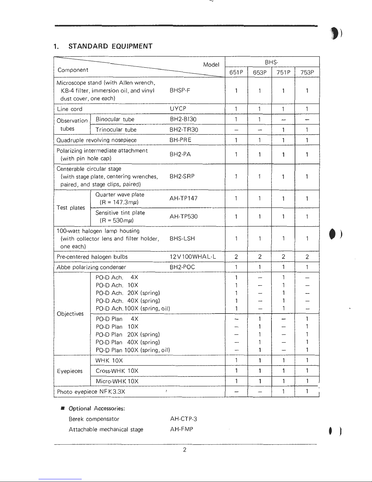
1.
STANDARD EQUIPMENT
Optional Accessories:
Berek compensator AH-CT P-3
Attachable mechanical stage AH-FMP
-
Model
Component
-------__-
Microscope stand (with Allen wrench,
KB-4 filter, immersion oil, and vinyl
BHSP-F
dust cover, one each)
Line cord UYCP
651P
1
1
1
-
1
1
1
1
1
1
2
1
1
1
1
1
1
-
-
-
-
-
1
1
1
-
Observation
tubes
Binocular tube BH2-B130
Trinocular tube
BH2-TR30
653P
1
1
1
-
1
1
1
1
1
1
2
1
-
-
-
-
1
1
1
1
1
1
1
1
-
Quadruple revolving nosepiece BH-PRE
Polarizing intermediate attachment
BH2-PA
(with pin hole cap)
Centerable circular stage
(with stage plate, centering wrenches,
BH2-SRP
paired, and stage clips, paired)
BHS-
751P
1
1
-
1
1
1
1
1
1
1
2
1
1
1
1
1
1
-
-
-
-
-
1
1
1
1
Test plates
753P
1
1
-
1
1
1
1
1
1
1
2
1
-
-
-
-
-
1
1
1
1
1
1
1
1
1
Quarter wave plate
(R
=
147.3my)
AH-TP147
-
Sensitive tint plate
(R
=
530my)
AH-TP530
100-watt halogen lamp housing
(with collector lens and filter holder,
BHS-LSH
one each)
Pre-centered halogen bulbs 12VlOOWHAL-L
Abbe polarizing condenser BH2-POC
Objectives
Eyepieces
PO-D Ach. 4X
PO-D Ach. 10X
PO-D Ach. 20X (spring)
PO-D Ach. 40X (spring)
PO-D Ach. 100X (spring, oil)
PO-D Plan 4X
PO-D Plan 10X
PO-D Plan 20X (spring)
PO-D Plan 40X (spring)
PO-D Plan 100X (spring, oil)
WHK 10X
Cross-WH
K
1 OX
Micro-WH
K
1 OX
Photo eyepiece NF K3.3X
11.
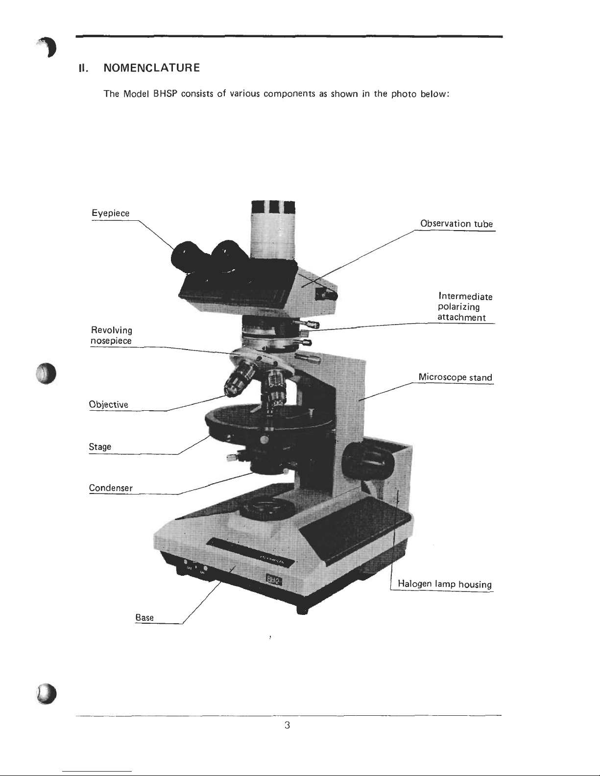
NOMENCLATURE
The Model
BHSP
consists of various components as shown in the photo below:
Revolving
nosepiece
Objective
Stage
Condenser
Base
Observation tube
,
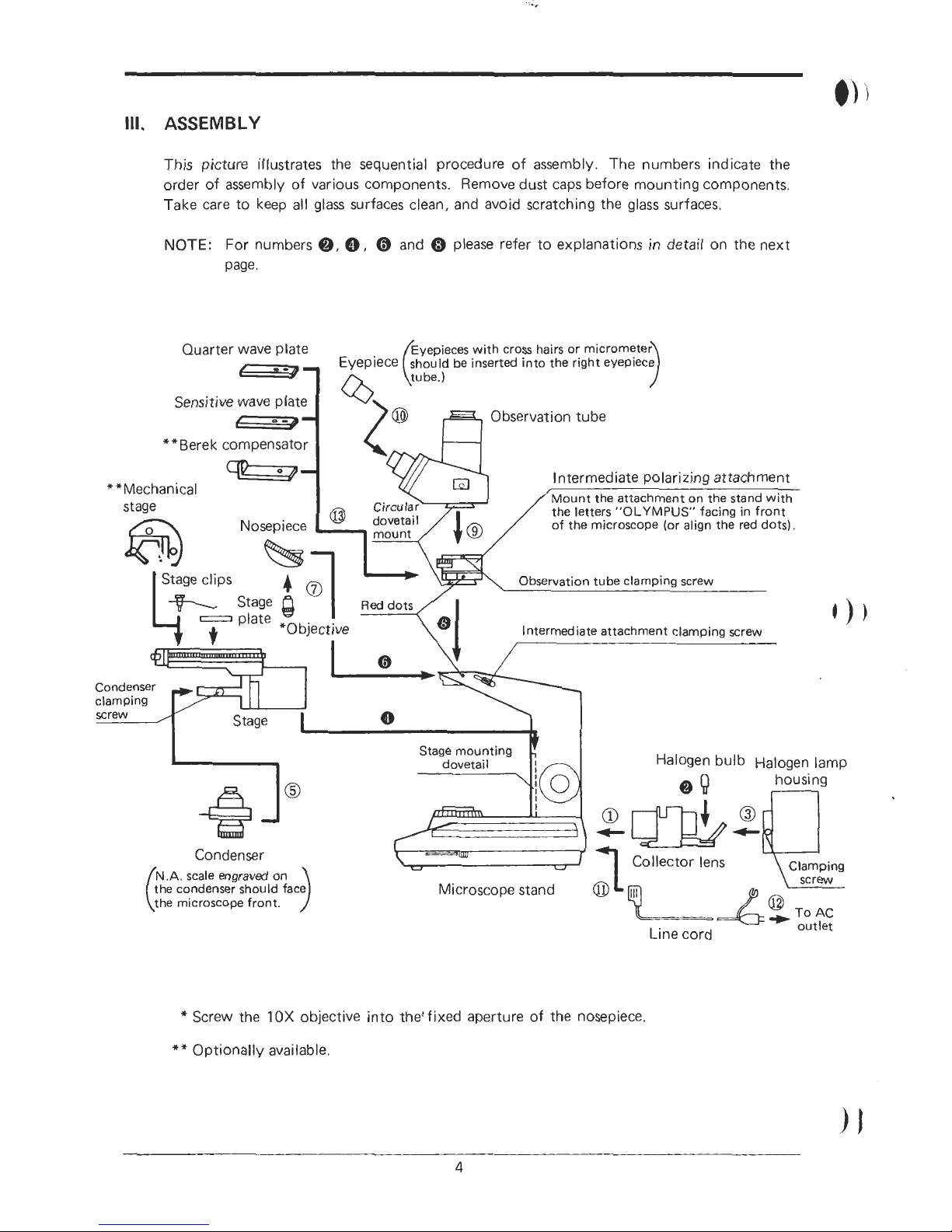
Ill.
ASSEMBLY
This picture illustrates the sequential procedure of assembly. The numbers indicate the
order of assembly
of
various components. Remove dust caps before mounting components.
Take care to keep all glass surfaces clean, and avoid scratching the glass surfaces.
NOTE:
For numbers
0,
0,
0
and 0 please refer to explanations in detail on the next
page.
Quarter wave plate
Sensitive wave plate
Observation tube
**Berek compensator
**Mechanical
Condenser
Collector lens
Microscope stand
*
Screw the
10X
objective into theJfixed aperture of the nosepiece.
**
Optionally available.
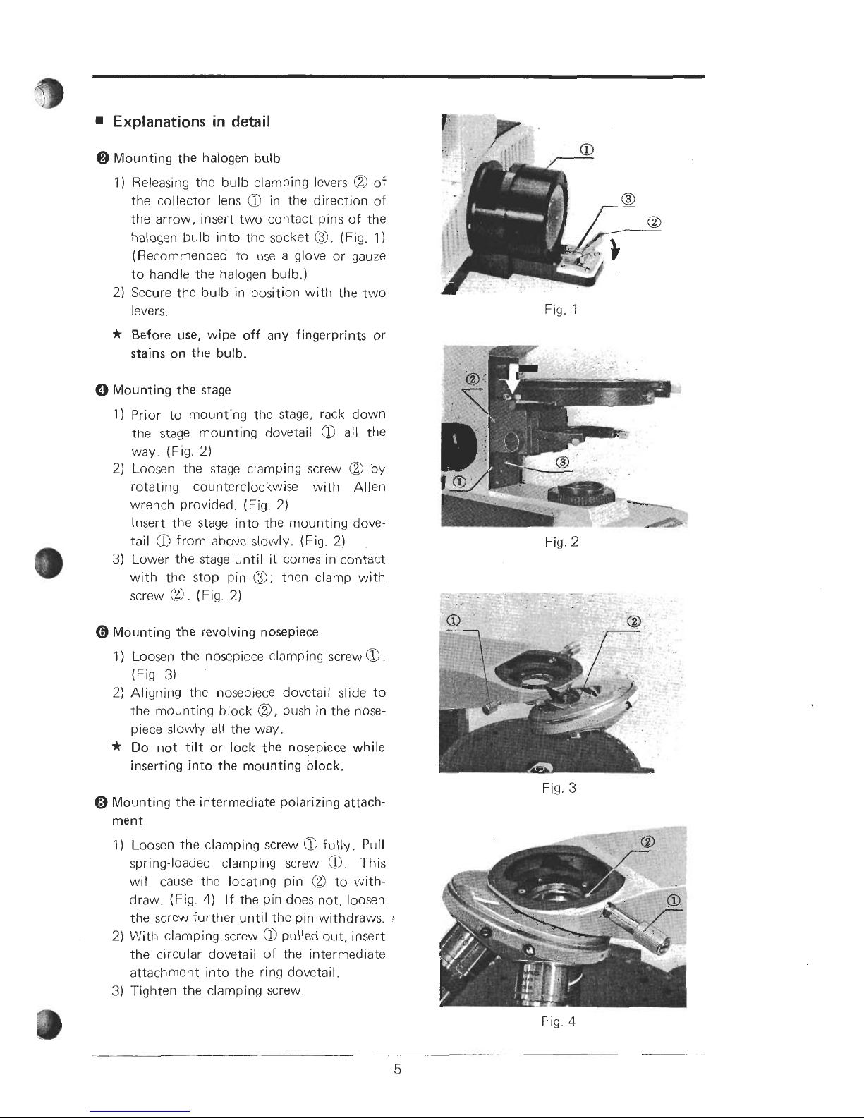
Explanations
in
detail
@
Mounting the halogen bulb
1)
Releasing the bulb clamping levers @ of
the collector lens
a
in the direction of
the arrow, insert two contact pins of the
halogen bulb into the socket
@.
(Fig.
1)
(Recommended to use a glove or gauze
to handle the halogen bulb.)
2)
Secure the bulb in position with the two
levers.
*
Before use, wipe off any fingerprints or
stains on the bulb.
0
Mounting the stage
1) Prior to mounting the stage, rack down
the stage mounting dovetail
a
all the
way. (Fig.
2)
2)
Loosen the stage clamping screw
@
by
rotating counterclockwise with Allen
wrench provided. (Fig.
2)
Insert the stage into the mounting dove-
tail
a
from above slowly. (Fig.
2)
3)
Lower the stage until it comes in contact
with the stop pin
0;
then clamp with
screw
@
.
(Fig.
2)
0
Mounting the revolving nosepiece
Fig. 1
Fig.
2
1)
Loosen the nosepiece clamping screw
a
(Fig.
3)
2)
Aligning the nosepiece dovetall slide to
the mounting block
@,
push in the nose-
piece
slowly all the way
*
Do
not
tilt
or lock the nosepiece while
inserting into the mounting block.
Mounting the intermediate polarizing attachment
1)
Loosen the clamping screw
a
fully. Pull
spring-loaded clamping screw
@.
This
will cause the locating pin
@
to with-
draw. (Fig.
4)
If the pin does not, loosen
the screw further until the pin withdraws.
!
2)
With clamping.screw 0 pulled out, insert
the circular dovetail of the intermediate
attachment into the ring dovetail.
3)
Tighten the clamping screw.
Fig.
3
Fig.
4
 Loading...