

Page 1
79
5 6
8
0
5
1
0
1 mm
min. 25 mm
min. 49 mm
min. 31 mmmin. 25 mm
min. 49 mm
min. 25 mm
4
4
3
2
1
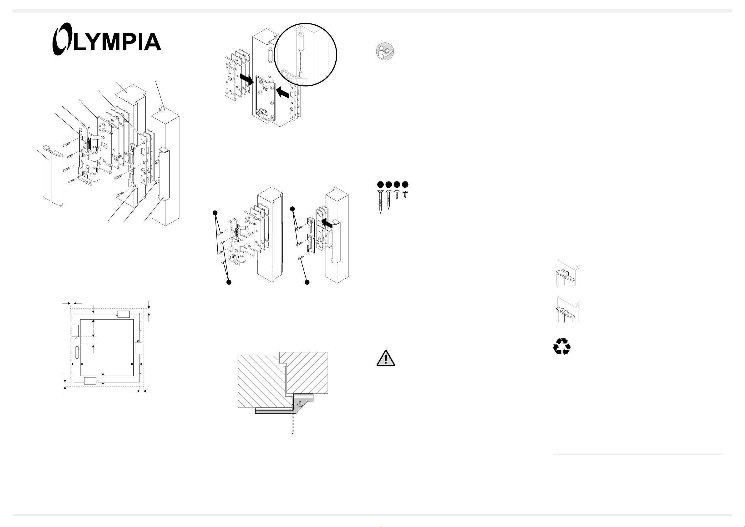
D Abb. 1 Übersicht
G Fig. 1 Overview
F Fig.1 Aperçu
I Fig. 1 Panoramica
n Afb. 1 Overzicht
E Fig. 1 Vista general
g Εικ.1 Σύνοψη
min. 49 mm
min. 140 mm
min. 49 mm
D Abb. 2 Montageposition / Mindestabstände
G Fig. 2 Assembly position / Minimum clearances
F Fig. 2 Position de montage / Distances minimum
I Fig. 2 Posizione di montaggio / Distanze minime
n Afb. 2 Montagepositie / minimale afstanden
E Fig. 2 Posición de montaje y distancias mínimas
g Εικ.2 Θέση συναρμολόγησης / ελάχιστες αποστάσεις
1
0
5
0
D Abb. 3 Montage auf Scharnierseite
G Fig. 3 Assembly on the hinge side
F Fig. 3 Montage côté charnière
I Fig. 3 Montaggio sul lato cerniera
n Afb. 3 Montage aan de scharnierzijde
E Fig. 3 Montaje en el lado de las bisagras
g Εικ.3 Συναρμολόγηση στην πλευρά μεντεσέδων
S2
S3
S1
S2
D Abb. 4 Schlosselement und Schlossanker montieren
G Fig. 4 Assembling the lock element and lock tting
F Fig. 4 Monter le verrou et l’ancre du verrou
I Fig. 4 Montaggio di elemento serratura e ssaggio serratura
n Afb. 4 Slotelement en slotanker monteren
E Fig. 4 Montar el elemento de bloqueo y el anclaje de bloqueo
g Εικ.4 Συναρμολόγηση στοιχείου κλειδαριάς και αγκυρίου
κλειδαριάς
D Abb. 5 Montage auf Schließseite/ Ober- bzw- Unterseite
G Fig. 5 Assembly on the closing side/ top or bottom side
F Fig. 5 Montage côté fermeture / côté supérieur ou inférieur
I Fig. 5 Montaggio sul lato chiusura, superiore o inferiore
n Afb. 5 Montage aan de sluit-, boven- of onderzijde
E Fig. 5 Montaje en el lado de cierre, lado superior o lado inferior
g Εικ.5 Συναρμολόγηση στην πλευρά κλεισίματος / στην πάνω
ή κάτω πλευρά
D Fenstersicherung ES-F1
(Art.-Nr. 6119)
Lesen Sie die Bedienungsanleitung aufmerksam durch und
beachten Sie die Hinweise bei der Handhabung. Bewahren Sie die
Bedienungsanleitung für eine spätere Verwendung auf.
Wichtiger Hinweis für Kunden, die zur Miete wohnen
Holen Sie sich vor der Montage der Fenstersicherung die schriftliche Erlaubnis Ihres Vermieters ein, da Sie für die Befestigung der Fenstersicherung
Löcher in den Fensterrahmen und -ügel bohren müssen.
Übersicht
Die Abbildung 1 zeigt Ihnen die Fenstersicherung im Detail.
1 Abdeckplatte 6 Rahmen
2 Schlosselement 7 Distanzkappe
3 Ver-/Entriegelung 8 Distanzhülsen
4 Distanzplatten 9 Schlossanker
5 Flügel
Montagematerial und Bohrertabelle
Im Lieferumfang der Fenstersicherung ist das folgende Montagematerial
enthalten.
S1S2S3 S4
Verwenden Sie je nach Auswahl des Montagematerials das passende
Werkzeug (Bohrer).
Schrauben Holz Kunstoff , Alu, Stahl
S1/S2 - 5,5 mm Ø 4 mm Ø 4,5 mm
S3/S4 - 4,8 mm Ø 3,5 mm Ø 4 mm
Bestimmungsgemäße Verwendung
Die Fenstersicherung ES-F1 - im Folgenden Fenstersicherung - dient zur
Sicherung von nach innen öffnenden Fenstern aus Holz, Aluminium, Stahl
oder Kunststoff. Voraussetzung für eine bestimmungsgemäße Verwendung
ist die sachgemäße Installation sowie die Beachtung und Einhaltung der
Hinweise dieser Bedienungsanleitung.
Jede andere Verwendung als in der bestimmungsgemäßen Verwendung
beschrieben gilt als nicht bestimmungsgemäß. Eigenmächtige Veränderungen oder Umbauten sind nicht zulässig und führen zur Beschädigung der
Fenstersicherung.
Sicherheitshinweise
Bewahren Sie sich vor körperlichen Schäden und beachten Sie die
Hinweise!
Wichtig! Unsachgemäße Montage kann zu Sachbeschädigungen führen.
Montieren Sie die Fenstersicherung ausschließlich wie in dieser Bedienungsanleitung abgebildet. Verwenden Sie ausschließlich das mitgelieferte
Montagematerial.
Verpackungsinhalt
Prüfen Sie den Verpackungsinhalt der Fenstersicherung, bevor Sie die
Fenstersicherung montieren nehmen. Sollte etwas fehlen oder beschädigt
sein, wenden Sie sich an unseren Service.
■ Fenstersicherung ES-F1, bestehend aus Schlosselement,
Schlossanker, Abdeckkappe und Distanzkappe
■ Montagematerial
■ Bohrschablone
■ 7x Distanzplatten breit
■ 5x Distanzplatten schmal
■ Bedienungsanleitung
Montageposition
Beachten Sie bei der Montage die in Abbildung 2 gezeigten Mindestabstände.
S1: 5,5 mm x 60 mm
S2: 5,5 mm x 50 mm
S3: 4,8 mm x 16 mm
S4: 4,8 mm x 13 mm
Warnung! Erstickungsgefahr! Kinder können Kleinteile,
Verpackungs- oder Schutzfolien verschlucken. Halten Sie Kinder
vom Produkt und dessen Verpackung fern!
Montage auf der Schließ-, Ober- bzw. Unterseite
Die Fenstersicherung kann an der Schließ-, Ober- oder Unterseite des
Fensters montiert werden.
1. Legen Sie die Bohrschablone mit 1 mm Luft zur Flügelkante auf die
benötigte Anzahl Distanzplatten (4) auf den Fensterrahmen. Beachten
Sie hierbei die Abbildung 5.
2. Merken Sie sich die benötigte Anzahl an Distanzplatten (4).
3. Fixieren Sie die Bohrschablone und lesen Sie das Maß ab.
4. Bohren Sie die Bohrlöcher entsprechend der Bohrschablone vor.
5. Nehmen Sie die Bohrschablone vom Fensterrahmen ab.
6. Bohren Sie die Bohrlöcher gemäß Bohrtabelle.
7. Legen Sie die benötigte Anzahl an Distanzplatten (3) unter das
Schlosselement (2) und schrauben Sie das Schlosselement (2) auf den
Fensterrahmen.
8. Legen Sie die benötigte Anzahl an Distanzplatten (3) unter den Schlossanker.
9. Setzen Sie die Distanzhülsen wie in Abbildung 4 gezeigt ein und
schrauben Sie den Schlossanker (9) auf den Fensterrahmen.
10. Setzen Sie die Abdeckkappe (1) auf das Schlosselement (2) auf.
11. Die Fenstersicherung ist auf der Schließ-, Ober bzw. Unterseite des
Fensters montiert.
Montage auf der Scharnierseite
Die Fenstersicherung kann an der Scharnierseite (Seite, zu der sich das
Fenster öffnet) des Fensters montiert werden.
1. Legen Sie die Bohrschablone auf die benötigte Anzahl Distanzplatten (4) auf den Fensterrahmen.
2. Merken Sie sich die benötigte Anzahl an Distanzplatten (3).
3. Richten Sie die Bohrschablone mit Hilfe der Justierspitze auf Achsenmitte des Fensterrahmens aus (siehe Abbildung 3).
4. Gehen Sie wie im Abschnitt Montage auf der Schließ-, Ober- bzw.
Unterseite ab Schritt 4 beschrieben vor.
Fenstersicherung verriegeln
1. Schließen Sie das Fenster.
2. Die Ver-/Entriegelung (3) arretiert automatisch in der
gezeigten Position.
Fenstersicherung entriegeln
1. Drücken Sie auf die Ver-/Entriegelung (3).
2. Die Ver-/Entriegelung löst sich und geht zurück in die
gezeigte Position.
3. Die Fenstersicherung ist entriegelt.
Entsorgung
Helfen Sie, die Umwelt zu schonen und entsorgen Sie das Produkt
und die Verpackungsmaterialien entsprechend den lokalen
Vorschriften.
Garantie
Die Garantiezeit beträgt 24 Monate. Die Garantiezeit beginnt ab Kaufdatum.
Bitte bewahren Sie den Kaufbeleg und die Originalverpackung auf. Sollte
ein Problem auftreten, besuchen Sie unser Retouren-Portal (RMA) im Bereich Support auf unserer Internetseite www.olympia-vertrieb.de.
Bei weiteren Fragen steht Ihnen unsere Hotline unter der Nummer
0180 5 007514 (Kosten aus dem dt. Festnetz bei Drucklegung: 14 ct/Min.,
mobil maximal 42 ct/Min.) zur Verfügung.
Olympia Business Systems Vertriebs GmbH
Zum Kraftwerk 1 - 45527 Hattingen
Technische Daten
Gewicht 560 g
Abmessungen (B x H x T) 70 x 182 x 35 mm
v1.0, 10.2018
Art. Nr. 6119
Page 2
G ES-F1 Window Lock
(Art. No. 6119)
Read the operating manual thoroughly and observe the information contained when using the device. Keep the operating manual
close by for future reference.
Important Information for Customers Who Are Tenants
Before assembling the window lock, obtain written approval to do so from
the landlord because assembly of the window lock necessitates drilling
holes in the window frame and casement.
General View
Figure 1 depicts the window lock in detail.
1 Face plate 6 Frame
2 Lock element 7 Spacer cap
3 Unlocking/Locking mechanism 8 Spacer sleeves
4 Spacer plates 9 Lock tting
5 Casement
Assembly Material and Drill Table
The following assembly material is contained in the package supplied for the
window lock.
S1S2S3 S4
Use the applicable tool (drill bit) according to the assembly materials selected.
Screws Wood Plastic, aluminium, steel
S1/S2 - 5.5 mm Ø 4 mm Ø 4.5 mm
S3/S4 - 4.8 mm Ø 3.5 mm Ø 4 mm
Intended Use
The ES-F1 window lock, subsequently referred to simply as window lock,
serves to secure inward opening windows made of wood, aluminium, steel
or plastic. A condition for complying with the intended use is that the equipment is installed correctly and the information in the manual is observed and
maintained.
Any use other than that described in the Section “Intended Use” is consid-
ered unintended use. Unauthorised modications or reconstructions are not
permitted and could cause damage to the window lock.
Safety Instructions
Avoid any personal injury by paying attention to the following information!
important! Improper assembly can lead to property damage. Only assem-
ble the window lock as described in this operating manual. Only use the
assembly material supplied.
Package Contents
Check the package contents of the window lock before starting to assemble the window lock. If anything is missing or damaged, please contact our
Service Department.
■ ES-F1 window lock, comprised of lock element,
lock tting, cover cap and spacer cap
■ Assembly material
■ Drilling template
■ 7x spacer plates, broad
■ 5x spacer plates, narrow
■ Operating manual
Installation Locations
When completing the assembly work, pay attention to the minimal clearances
specied in Figure 2.
Assembling on the Closing, Top or Bottom Side
S1: 5.5 mm x 60 mm
S2: 5.5 mm x 50 mm
S3: 4.8 mm x 16 mm
S4: 4.8 mm x 13 mm
Warning! Risk of suffocation! Children can swallow small parts,
packaging and protective foils. Keep the product and packaging
out of reach of children!
The window lock can be mounted on the closing, top or bottom side of the
window.
1. Lay the drilling template with 1 mm clearance to the edge of the window
casement on the required number of spacer plates (4) on the window
frame. At this point, pay attention to Figure 5.
2. Note the number of spacer plates (4) required.
3. Fix the drilling template and read the dimension.
4. Drill the drill holes according to the drilling template.
5. Remove the drilling template from the window frame.
6. Drill the drill holes according to the drilling table.
7. Lay the required number of spacer plates (3) under the lock element (2)
and screw the lock element (2) to the window frame.
8. Lay the required number of spacer plates (3) under the lock tting.
9. Insert the spacer sleeves as illustrated in Figure 4 and screw the lock
tting (9) to the window frame.
10. Fit the cover cap (1) on the lock element (2).
11. The window lock is now assembled on the closing, top or bottom side
of the window.
Assembling on the Hinge Side
The window lock can be assembled on the hinge side (the side towards
which the window opens) of the window.
1. Lay the drilling template on the required number of spacer plates (4) on
the window frame.
2. Note the number of spacer plates (3) required.
3. Align the drilling template to the centre of the axis of the window frame
with the aid if the adjusting tip (see Figure 3).
4. Proceed as described in Section “Assembling on the Closing, Top or
Bottom Side” from Step 4.
Locking the Window Lock
1. Close the window.
2. The unlocking/locking mechanism (3) automatically locks
in the position illustrated.
Unlocking the Window Lock
1. Press on the unlocking/locking mechanism (3).
2. The unlocking/locking mechanism is released and
returns to the position illustrated.
3. The window lock is unlocked.
Disposal
Help protect the environment and dispose of the product and
packaging materials according to the applicable local regulations.
Guarantee
The period of guarantee is 24 months. The period of guarantee begins on
the date of purchase. It is essential to keep the purchase receipt and original
packaging. If a problem arises, please refer to our Return Merchandise
Authorisation portal (RMA) in the Support section of our website at
www.olympia-vertrieb.de.
In the case of further queries, please contact our hotline 0180 5 007514
(costs via German landline at time of going to print: 14 ct/min.,
max. 42 ct/min. via a mobile network).
Olympia Business Systems Vertriebs GmbH
Zum Kraftwerk 1 - 45527 Hattingen
Technical Data
Weight 560 g
Dimensions (W x H x D) 70 x 182 x 35 mm
v1.0, 10.2018
Art. No. 6119
F Verrou pour fenêtre ES-F1
(n° art. 6119)
Veuillez lire attentivement cette notice d’utilisation et respecter les
consignes lorsque vous manipulez le verrou. Conservez-celle-ci
pour une utilisation ultérieure.
Information importante pour les clients qui habitent en
location.
Avant d’installer le verrou pour fenêtre, vous devez obtenir l’autorisation
écrite de votre loueur car vous devez percer des trous dans le dormant et le
battant de la fenêtre pour le xer.
Aperçu
La gure 1 vous montre le verrou pour fenêtre en détail.
1 Cache de recouvrement 6 Dormant
2 Verrou 7 Cache d'écartement
3 Disp. verr./déverrouillage 8 Douilles d'écartement
4 Plaques d'écartement 9 Ancre du verrou
5 Battant
Matériel de montage et tableau de perçage
Le matériel de montage suivant fait partie du contenu du coffret du verrou
pour fenêtre.
S1S2S3 S4
Utilisez l’outil adéquat (perceuse) en fonction du matériel de montage que
vous aurez choisi.
Vis Bois Plastique, aluminium, acier
S1/S2 - 5,5 mm Ø 4 mm Ø 4,5 mm
S3/S4 - 4,8 mm Ø 3,5 mm Ø 4 mm
Utilisation conforme à l’usage prévu
Le verrou pour fenêtre ES-F1 - appelé par la suite verrou pour fenêtre - sert
de protection pour les fenêtres s’ouvrant à l’intérieur en bois, aluminium,
acier ou matière synthétique. L’utilisation conforme à l’usage prévu requiert
une installation appropriée, ainsi que l’observation et le respect des remarques mentionnées dans la présente notice d’utilisation.
Toute utilisation autre que celle décrite au point Utilisation conforme à
l’usage prévu est considérée comme non conforme. Des modications ou
transformations effectuées d’un propre gré sont interdites et conduisent à un
endommagement du verrou.
Consignes de sécurité
Préservez-vous de dommages corporels et tenez compte des remarques !
important ! Un montage impropre peut entraîner des dommages maté-
riels. Installez le verrou pour fenêtre uniquement comme représenté sur la
gure. N’utilisez que le matériel de montage fourni.
Contenu du coffret
Contrôlez le contenu de l’emballage du verrou pour fenêtre avant de l’installer. Veuillez vous adresser à notre service après-vente si une pièce manque
ou est endommagée.
■ Verrou pour fenêtre ES-F1, composé d’un verrou, d’une ancre,
d’un cache de recouvrement et d’un cache d’écartement
■ Matériel de montage
■ Gabarit de perçage
■ 7 plaques d’écartement larges
■ 7 plaques d’écartement étroites
■ Notice d’utilisation
Position de montage
Tenez compte lors du montage des distances minimum indiquées à la
gure 2.
S1 : 5,5 mm x 60 mm
S2 : 5,5 mm x 50 mm
S3 : 4,8 mm x 16 mm
S4 : 4,8 mm x 13 mm
avertissement ! Risque d’étouffement ! Les enfants peuvent
avaler des petites pièces, des lms d’emballage ou de protection.
Tenez les enfants à l’écart du produit et de son emballage !
Montage sur côté fermeture, supérieur ou inférieur.
Vous pouvez installer le verrou pour fenêtre côté fermeture, supérieur ou
inférieur de la fenêtre
1. Sur le dormant de la fenêtre, posez le gabarit de perçage avec 1 mm
d’écart par rapport au bord du battant sur le nombre requis de plaques
d’écartement (4). Reportez-vous à la gure 5.
2. Notez le nombre requis de plaques (4).
3. Fixez le gabarit et relevez la cote.
4. Percez les avant-trous d’après le gabarit.
5. Retirez ce dernier du dormant.
6. Percez les trous d’après la table de perçage.
7. Posez le nombre requis de plaques d’écartement (3) sous le verrou (2)
et vissez ce verrou (2) sur le dormant de la fenêtre.
8. Posez le nombre requis de plaques d’écartement (3) sous l’ancre du
verrou.
9. Introduisez les douilles d’écartement comme représenté à la gure 4 et
vissez l’ancre (9) sur le dormant.
10. Remettez le cache (1) sur le verrou (2).
11. Le verrou pour fenêtre est installé côté fermeture, supérieur ou inférieur
de la fenêtre.
Montage côté charnière
Vous pouvez installer le verrou pour fenêtre côté charnière (le côté où
s’ouvre la fenêtre).
1. Sur le dormant de la fenêtre, posez le gabarit de perçage sur le nombre
requis de plaques d’écartement (4).
2. Notez le nombre requis de plaques (3).
3. Alignez le gabarit de perçage à l’aide de la pointe de réglage sur le
milieu du dormant de la fenêtre (cf. Figure 3).
4. Procédez comme à la section Montage sur côté fermeture, supérieur
ou inférieur à partir de l’étape 4.
Verrouiller le verrou pour fenêtre ES-F1
1. Fermez la fenêtre.
2. Le dispositif de verr./déverrouillage (3) bloque automati
quement dans la position indiquée.
Déverrouiller le verrou pour fenêtre
1. Appuyez sur le dispositif de verr./déverrouillage (3).
2. Celui-ci se débloque et retourne dans la position
indiquée.
3. Le verrou pour fenêtre est déverrouillé.
Recyclage
Faites preuve d’un souci écologique et recyclez l’appareil et les
fournitures d’emballage conformément aux règlements locaux.
Garantie
La période de garantie est de 24 mois. Elle débute à la date d’achat.
Conservez soigneusement le bon d’achat et l’emballage d’origine. En cas
de problème, visitez notre portail des retours (RMA) à la rubrique Support
sur notre site Internet www.olympia-vertrieb.de.
Si vous avez des questions supplémentaires, composez le numéro de notre
hotline 0180 5 007514 (frais au moment de l’impression de ce manuel :
14 ct/min à partir du réseau xe ; maximum 42 ct/min depuis les réseaux
mobiles).
Olympia Business Systems Vertriebs GmbH
Zum Kraftwerk 1 - 45527 Hattingen
Données techniques
Poids 560 g
Dimensions (l x H x E) 70 x 182 x 35 mm
v1.0, 10.2018
N° art. 6119
I Protezione nestra ES-F1
(Codice 6119)
Leggere attentamente le istruzioni d’uso e osservare le indicazioni
durante l’utilizzo. Conservare le istruzioni d’uso per riferimento
futuro.
Nota importante per clienti che vivono in aftto
Prima di montare la protezione nestra è necessario farsi rilasciare un’apposita autorizzazione scritta da parte del proprio locatore, dato che il montag-
gio della protezione nestra richiede l’esecuzione di fori in telaio e battente
degli inssi interessati.
Vista generale
La gura 1 visualizza la protezione nestra in dettaglio.
1 Copertura esterna 6 Telaio
2 Elemento serratura 7 Copertura distanziali
3 Dispositivo di blocco/sblocco 8 Boccole distanziali
4 Piastre distanziali 9 Fissaggio serratura
5 Battente
Materiale di montaggio e tabella delle punte trapano
La fornitura della protezione nestra comprende il seguente materiale di
montaggio:
S1S2S3 S4
In base al materiale di montaggio scelto, si prega di utilizzare gli attrezzi
richiesti (trapano).
Viti Legno Plastica, alluminio, acciaio
S1/S2 - 5,5 mm Ø 4 mm Ø 4,5 mm
S3/S4 - 4,8 mm Ø 3,5 mm Ø 4 mm
Impiego conforme agli usi previsti
La protezione nestra ES-F1 - qui di seguito protezione nestra - è preposta
a proteggere nestre in legno, alluminio, acciaio o plastica da un’apertura
dall’esterno verso l’interno. Requisito per un impiego conforme è il corretto
montaggio come anche l’osservanza delle indicazioni fornite nelle presenti
istruzioni d’uso.
Qualsiasi impiego diverso da quanto descritto è ritenuto non conforme agli
usi previsti. Non sono ammesse modiche o variazioni arbitrarie che potrebbero causare il danneggiamento della protezione nestra.
Indicazioni di sicurezza
Evitare lesioni siche e osservare le indicazioni!
importante! Un montaggio improprio può essere causa di danni materiali.
Montare la protezione nestra esclusivamente secondo quanto rafgurato
nelle istruzioni d’uso. Utilizzare esclusivamente il materiale di montaggio
fornito in dotazione.
Contenuto della confezione
Vericare il contenuto della confezione della protezione nestra prima di procedere al relativo montaggio. In caso dovesse mancare qualcosa o risultare
danneggiato, si prega di rivolgersi al nostro servizio di assistenza.
■ Protezione nestra ES-F1, composta da elemento serratura,
ssaggio serratura, copertura esterna e copertura distanziali
■ Materiale di montaggio
■ Sagoma di trapanatura
■ 7 piastre distanziali larghe
■ 5 piastre distanziali strette
■ Istruzioni d’uso
Posizione di montaggio
Osservare durante il montaggio le distanze minime visualizzate nella gura 2.
S1: 5,5 mm x 60 mm
S2: 5,5 mm x 50 mm
S3: 4,8 mm x 16 mm
S4: 4,8 mm x 13 mm
avvertenza! Pericolo di soffocamento! I bambini possono
ingerire parti piccole, materiali d’imballo o pellicole protettive.
Tenere il prodotto e la confezione lontani dalla portata dei
bambini!
Montaggio su lato chiusura, superiore o inferiore
La protezione nestra può essere montata sul lato chiusura, sul lato superiore o sul lato inferiore della nestra.
1. Posizionare la sagoma di trapanatura sul telaio dell’insso, con 1 mm
di distanza dal bordo del battente e considerando il numero di piastre
distanziali (4) necessarie. Osservare allo scopo la gura 5.
2. Prendere nota del numero di piastre distanziali (4) necessarie.
3. Fissare la sagoma di trapanatura e rilevare la misura richiesta.
4. Demarcare i fori nei punti indicati dalla sagoma di trapanatura.
5. Rimuovere la sagoma di trapanatura dal telaio della nestra.
6. Effettuare i fori nei punti demarcati conformemente a quanto indicato
nella tabella delle punte trapano.
7. Prevedere il numero di piastre distanziali (3) necessarie sotto all’elemento serratura (2) ed avvitare quindi l’elemento serratura (2) sul telaio
della nestra.
8. Prevedere il numero di piastre distanziali (3) necessarie sotto al ssaggio serratura.
9. Posizionare le boccole distanziali secondo quanto visualizzato nella
gura 4 e avvitare il ssaggio serratura (9) sul telaio della nestra.
10. Applicare la copertura esterna (1) sull’elemento serratura (2).
11. La protezione nestra risulta montata sul lato chiusura, superiore o
inferiore della nestra.
Montaggio sul lato cerniera
La protezione nestra può essere montata sul lato cerniera (lato verso il
quale si apre la nestra) della nestra.
1. Posizionare la sagoma di trapanatura sul telaio dell’insso considerando il numero di piastre distanziali (4) necessarie.
2. Prendere nota del numero di piastre distanziali (3) necessarie.
3. Allineare la sagoma di trapanatura con l’ausilio della punta di regolazio-
ne in direzione centro dell’asse del telaio della nestra (vedi gura 3).
4. Procedere secondo quanto descritto nella sezione Montaggio su lato
chiusura, superiore o inferiore a partire dal punto 4.
Bloccare la protezione nestra
1. Chiudere la nestra.
2. Il dispositivo di blocco/sblocco (3) si arresta automatica mente nella posizione visualizzata.
Sbloccare la protezione nestra
1. Premere sul dispositivo di blocco/sblocco (3).
2. Il dispositivo di blocco/sblocco è rilasciato e torna indie tro nella posizione visualizzata.
3. La protezione nestra risulta sbloccata.
Smaltimento
I consumatori possono contribuire alla protezione dell’ambiente.
Procedere pertanto allo smaltimento di prodotto e materiali
d’imballo conformemente alle norme locali in vigore.
Garanzia
Il periodo di garanzia copre 24 mesi. Il periodo di garanzia decorre dalla
data di acquisto. Vi preghiamo di conservare lo scontrino di acquisto e la
confezione originale. In caso di problemi, visitate il nostro portale resi (RMA)
nell’area Support sul nostro sito internet www.olympia-vertrieb.de.
Per ulteriori domande contattate la nostra linea di assistenza al numero
0180 5 007514 (spese da rete ssa tedesca alla data di stampa: 14 ct/min.,
max. 42 ct/min. da rete mobile).
Olympia Business Systems Vertriebs GmbH
Zum Kraftwerk 1 - D-45527 Hattingen
Speciche tecniche
Peso 560 g
Dimensioni (L x H x P) 70 x 182 x 35 mm
v1.0, 10.2018
Codice 6119
n Raamvergrendeling ES-F1
(art.nr. 6119)
Lees de gebruiksaanwijzing aandachtig door en volg de instructies
op bij het omgaan met het product. Bewaar de gebruiksaanwijzing
voor toekomstig gebruik.
Belangrijke informatie voor klanten die gehuurd wonen
Vraag de schriftelijke toestemming van uw verhuurder voordat u de raamvergrendeling installeert, omdat u gaten in het raamkozijn en de raamvleugel moet boren om de raamvergrendeling te bevestigen.
Overzicht
Afbeelding 1 toont de raamvergrendeling in detail.
1 Afdekplaat 6 Raam
2 Slotelement 7 Afstandskap
3 Ver-/ontgrendeling 8 Afstandsbussen
4 Afstandsplaten 9 Slotanker
5 Vleugel
Montagemateriaal en boortabel
Bij de raamvergrendeling wordt het volgende montagemateriaal geleverd.
S1S2S3 S4
Gebruik afhankelijk van de keuze van het montagemateriaal het juiste
gereedschap (boor).
Schroeven Hout Kunststof, aluminium, staal
S1/S2 – 5,5 mm Ø 4 mm Ø 4,5 mm
S3/S4 – 4,8 mm Ø 3,5 mm Ø 4 mm
Beoogd gebruik
De raamvergrendeling ES-F1 – hierna raamvergrendeling genoemd – dient
als beveiliging van naar binnen openende ramen van hout, aluminium, staal
of kunststof. Voorwaarde voor het beoogde gebruik is de juiste installatie en
naleving van de instructies in deze gebruiksaanwijzing.
Elk ander gebruik dan beschreven in het beoogde gebruik wordt beschouwd
als oneigenlijk. Ongeoorloofde wijzigingen of aanpassingen zijn niet toegestaan en leiden tot beschadiging van de raamvergrendeling.
Veiligheidsinformatie
Bescherm uzelf tegen persoonlijk letsel en volg de instructies op!
Belangrijk ! Verkeerde montage kan schade veroorzaken. Monteer
de raamvergrendeling uitsluitend zoals in deze gebruiksaanwijzing wordt
getoond. Gebruik alleen het bijgeleverde montagemateriaal.
Inhoud van de verpakking
Controleer de inhoud van de verpakking van de raamvergrendeling, voordat
u de raamvergrendeling monteert. Als er iets ontbreekt of beschadigd is,
neem contact op met onze serviceafdeling.
■ Raamvergrendeling ES-F1, bestaande uit slotelement,
Slotanker, afdekkap en afstandskap
■ Montagemateriaal
■ Boormal
■ 7x afstandsplaten breed
■ 5x afstandsplaten smal
■ Gebruiksaanwijzing
Montagepositie
Let bij de montage op de in afbeelding 2 getoonde minimale afstanden.
S1: 5,5 mm x 60 mm
S2: 5,5 mm x 50 mm
S3: 4,8 mm x 16 mm
S4: 4,8 mm x 13 mm
WaarschuWing! Verstikkingsgevaar! Kinderen kunnen kleine
onderdelen, verpakkings- of beschermfolies inslikken. Houd
kinderen uit de buurt van het product en zijn verpakking!
Montage aan de sluit-, boven- of onderzijde
De raamvergrendeling kan aan de sluit-, boven- of onderzijde van het raam
worden gemonteerd.
1. Plaats de boormal op 1 mm afstand van de rand van de vleugel op het
benodigde aantal afstandsplaten (4) op het raamkozijn. Let hierbij op
afbeelding 5.
2. Onthoud het benodigde aantal afstandsplaten (4).
3. Bevestig de boormal en lees de maat af.
4. Boor de gaten volgens de boormal voor.
5. Verwijder de boormal van het raamkozijn.
6. Boor de gaten volgens de boortabel.
7. Plaats het benodigde aantal afstandsplaten (3) onder het slotelement (2) en schroef het slotelement (2) op het raamkozijn.
8. Plaats het benodigde aantal afstandsplaten (3) onder het slotanker.
9. Plaats de afstandsbussen zoals getoond in afbeelding 4 en schroef het
slotanker (9) op het raamkozijn.
10. Plaats de afdekkap (1) op het slotelement (2).
11. De raamvergrendeling is aan de sluit-, boven- of onderzijde van het
raam gemonteerd.
Montage aan de scharnierzijde
De raamvergrendeling kan aan de scharnierzijde (zijde waarnaartoe het
raam opent) van het raam worden gemonteerd.
1. Plaats de boormal op het benodigde aantal afstandsplaten (4) op het
raamkozijn.
2. Onthoud het benodigde aantal afstandsplaten (3).
3. Lijn de boormal met behulp van de uitlijningspunt uit op het midden van
de as van het raamkozijn (zie afbeelding 3).
4. Ga te werk zoals beschreven in de paragraaf Montage aan de sluit-,
boven- of onderzijde, beginnend met stap 4.
Raamvergrendeling vergrendelen
1. Sluit het raam.
2. De ver-/ontgrendeling (3) wordt automatisch vergren
deld in de getoonde positie .
Raamvergrendeling ontgrendelen
1. Druk op de ver-/ontgrendeling (3).
2. De ver-/ontgrendeling wordt vrijgegeven en keert terug
naar de getoonde positie .
3. De raamvergrendeling is ontgrendeld.
Gescheiden inzameling
Help mee om het milieu te beschermen en voer het product en het
verpakkingsmateriaal af in overeenstemming met de plaatselijke
regelgeving.
Garantie
De garantieperiode bedraagt 24 maanden. De garantieperiode gaat in
op de datum van aankoop. Bewaar a.u.b. de aankoopbon en de originele
verpakking. Als u een probleem ondervindt, gaat u op onze retourenportal
(RMA) op onze website www.olympia-vertrieb.de naar het gebied Support.
Voor verdere vragen kunt u contact opnemen met onze hotline op (0049)
180 5 007514 (kosten vanuit het Duitse vaste net op het moment van druk:
14 ct/min, mobiel maximaal 42 ct/min).
Olympia Business Systems Vertriebs GmbH
Zum Kraftwerk 1 – 45527 Hattingen (D)
Technische gegevens
Gewicht 560 g
Afmetingen (b x h x d) 70 x 182 x 35 mm
v1.0, 10.2018
Art.nr. 6119
Page 3

E Protección de ventana ES-F1
(N.º art. 6119)
Lea el manual de instrucciones atentamente y tenga en cuenta las
advertencias relativas al manejo. Guarde el manual de instrucciones para cualquier utilización posterior.
Advertencia importante para clientes que viven en alquiler
Antes de montar la protección de ventana debe solicitar la autorización
escrita de su arrendador ya que debe taladrar unos agujeros en el marco y
la hoja de la ventana para la jación de la protección de ventana.
Vista general
La gura 1 muestra la protección de ventana en detalle.
1 Placa de cubierta 6 Marco
2 Elemento de bloqueo 7 Caperuza distanciadora
3 Enclavamiento/desenclavamiento 8 Casquillos distanciadores
4 Placas distanciadoras 9 Anclaje de bloqueo
5 Hoja
Material de montaje y tabla de brocas
El volumen de suministro de la protección de ventana incluye el siguiente
material de montaje.
S1S2S3 S4
Utilice la herramienta adecuada (broca) en función del material de montaje.
Tornillos Madera Plástico, aluminio, acero
S1/S2 - 5,5 mm Ø 4 mm Ø 4,5 mm
S3/S4 - 4,8 mm Ø 3,5 mm Ø 4 mm
Uso previsto
La protección de ventana ES-F1 (en lo sucesivo “protección de ventana”)
sirve como protección para ventanas de madera, aluminio, acero o plástico,
que se abren hacia dentro. La observación y el cumplimiento de las adver-
tencias que guran en el presente manual de instrucciones son requisito
para el correcto uso del aparato.
Cualquier otro uso diferente al previsto se considera como no conforme
al objetivo previsto. Se prohíbe expresamente cualquier modicación o
transformación por cuenta propia que además puede provocar daños en la
protección de ventana.
Advertencias de seguridad
¡Tenga cuidado de no sufrir daños físicos y tenga en cuenta las notas de
advertencia!
¡importante! Un montaje incorrecto puede dar lugar a daños materiales.
Monte la protección de ventana exclusivamente según las ilustraciones de
este manual de instrucciones. Utilice exclusivamente el material de montaje
suministrado.
Contenido del embalaje
Antes de montar la protección de ventana, compruebe el contenido del embalaje. Diríjase a nuestro Servicio Técnico si falta algo o se observan daños.
■ La protección de ventana ES-F1, consta de un elemento de bloqueo,
un anclaje de bloqueo, caperuza de cubrimiento y caperuza distanciadora
■ Material de montaje
■ Plantilla para taladrar
■ 7 placas distanciadoras anchas
■ 5 placas distanciadoras estrechas
■ Manual de instrucciones
Posición de montaje
Tenga en cuenta a la hora del montaje las distancias mínimas mostradas en
la gura 2.
S1: 5,5 mm x 60 mm
S2: 5,5 mm x 50 mm
S3: 4,8 mm x 16 mm
S4: 4,8 mm x 13 mm
¡aviso! ¡Peligro de asxia! Los niños pueden tragar piezas
pequeñas, películas de embalaje o protección. ¡Mantenga
alejados a los niños del producto y de su embalaje!
Montaje en el lado de cierre, lado superior o lado inferior
La protección de ventana se puede montar en el lado de cierre, lado superior o lado inferior.
1. Coloque la plantilla para taladrar con 1 mm de distancia con respecto
al borde de la hoja sobre la cantidad necesaria de placas distanciado-
ras (4) sobre el marco de la ventana. Tenga en cuenta la gura 5.
2. Memorice la cantidad necesaria de placas distanciadoras (4).
3. Fije la plantilla para taladrar y lea la medida.
4. Marque los taladros según la plantilla para taladrar.
5. Retire la plantilla para taladrar del marco de la ventana.
6. Realice los taladros conforme a la tabla de taladrado.
7. Coloque la cantidad necesaria de placas distanciadoras (3) debajo del
elemento de bloqueo (2) y atorníllelo al marco de la ventana.
8. Coloque la cantidad necesaria de placas distanciadoras (3) debajo del
anclaje de bloqueo.
9. Inserte los casquillos distanciadores según la gura 4 y atronille el
anclaje de bloqueo (9) al marco de la ventana.
10. Coloque la caperuza de cubrimiento (1) sobre el elemento de bloqueo (2).
11. La protección de ventana está montada en el lado de cierre, lado superior o lado inferior de la ventana.
Montaje en el lado de las bisagras
La protección de ventana se puede montar en el lado donde están situadas
las bisagras de la ventana (lado hacia el que se abre la ventana).
1. Coloque la plantilla para taladrar sobre la cantidad necesaria de placas
distanciadoras (4) sobre el marco de la ventana.
2. Memorice la cantidad necesaria de placas distanciadoras (3).
3. Alinee la plantilla para taladrar con la punta de alineación con respecto
al centro del eje del marco de la ventana (ver la gura 3).
4. Proceda según la descripción del apartado sobre montaje en el lado de
cierre, lado superior o lado inferior a partir del paso 4.
Bloquear la protección de ventana
1. Cierre la ventana.
2. El enclavamiento/desenclavamiento (3) realiza el
bloqueo automáticamente en la posición mostrada.
Desbloquear la protección de ventana
1. Pulse el enclavamiento/desenclavamiento (3).
2. El enclavamiento/desenclavamiento se suelta y vuelve
a la posición mostrada.
3. La protección de ventana está desbloqueada.
Eliminación
Ayude a proteger el medio ambiente y elimine el producto y los
materiales de embalaje según las prescripciones locales.
Garantía
El plazo de garantía es de 24 meses. El plazo de garantía comienza a partir
de la fecha de compra. Guarde el justicante de compra y el embalaje original. En caso de que surja cualquier problema, puede visitar nuestro portal
para devoluciones (RMA) en la sección de asistencia técnica de nuestra
página web www.olympia-vertrieb.de.
En caso de tener otras preguntas, tiene a su disposición nuestra línea
de asistencia telefónica en el número 0180 5 007514 (coste de la red ja
alemana en el momento de impresión: 14 céntimos/minuto, desde redes
móviles 42 céntimos/minuto como máximo).
Olympia Business Systems Vertriebs GmbH
Zum Kraftwerk 1 - 45527 Hattingen
Datos técnicos
Peso 560 g
Dimensiones (An x Al x Pr) 70 x 182 x 35 mm
v1.0, 10.2018
N.º art. 6119
g Ασφάλεια παραθύρου ES-F1
(Αριθμός είδους 6119)
Διαβάστε προσεκτικά τις Οδηγίες Χρήσης και προσέξτε τις
υποδείξεις κατά τον χειρισμό. Φυλάξτε τις Οδηγίες Χρήσης για
μετέπειτα αναφορά.
Σημαντική υπόδειξη για πελάτες που διαμένουν σε
ενοικιαζόμενες κατοικίες
Πριν από την τοποθέτηση της ασφάλειας παραθύρου ζητήστε την έγγραφη
άδεια του εκμισθωτή, καθώς για τη στερέωση της ασφάλειας παραθύρου
πρέπει να διανοίξετε οπές στο πλαίσιο και στο φύλλο του παραθύρου.
Σύνοψη
Η εικόνα 1 σας δείχνει λεπτομερώς την ασφάλεια παραθύρου.
1 Πλάκα κάλυψης 6 Πλαίσιο
2 Στοιχείο κλειδαριάς 7 Αποστατικό καπάκι
3 Κλείδωμα/ξεκλείδωμα 8 Αποστατικά χιτώνια
4 Αποστατικές πλάκες 9 Αγκύριο κλειδαριάς
5 Φύλλο
Υλικό συναρμολόγησης και πίνακας τρυπανιών
Στο περιεχόμενο παράδοσης της ασφάλειας παραθύρου περιλαμβάνεται το
ακόλουθο υλικό συναρμολόγησης.
S1S2S3 S4
Ανάλογα με την επιλογή του υλικού συναρμολόγησης επιλέξτε το κατάλληλο
εργαλείο (τρυπάνι).
Βίδες Ξύλο Πλαστικό, αλουμίνιο, χάλυβας
S1/S2 - 5,5 mm Ø 4 mm Ø 4,5 mm
S3/S4 - 4,8 mm Ø 3,5 mm Ø 4 mm
Χρήση σύμφωνη με τον προορισμό
Η ασφάλεια παραθύρου ES-F1 - εφεξής ασφάλεια παραθύρου - χρησιμεύει
στην ασφάλιση ξύλινων, αλουμινένιων, χαλύβδινων ή πλαστικών παραθύρων
που ανοίγουν από μέσα. Προϋπόθεση για τη χρήση σύμφωνα με τον προορισμό αποτελεί η σωστή εγκατάσταση σύμφωνα με τους κανόνες καθώς και η
ενημέρωση και τήρηση των υποδείξεων σε αυτές τις Οδηγίες Χρήσης.
Κάθε άλλη χρήση θεωρείται ως μη σύμφωνη με τον προορισμό. Τροποποιήσεις και μετατροπές χωρίς άδεια απαγορεύονται και προκαλούν ζημιά στην
ασφάλεια παραθύρου.
Υποδείξεις ασφαλείας
Προστατέψετε τον εαυτό σας από σωματικές βλάβες και να λαμβάνετε
υπόψη σας τις παρατηρήσεις!
σημαντικο! Η μη ενδεδειγμένη συναρμολόγηση μπορεί να οδηγήσει σε υλι-
κές ζημιές. Συναρμολογήστε την ασφάλεια παραθύρου αποκλειστικά όπως
απεικονίζεται στις παρούσες Οδηγίες Χρήσης. Χρησιμοποιήστε αποκλειστικά το συνοδευτικό υλικό συναρμολόγησης.
Περιεχόμενο συσκευασίας
Ελέγξτε το περιεχόμενο συσκευασίας της ασφάλειας παραθύρου, προτού
συναρμολογήσετε την ασφάλεια παραθύρου. Αν λείπει κάτι ή έχει υποστεί
ζημιά, απευθυνθείτε στο Service μας.
■ Ασφάλεια παραθύρου ES-F1, αποτελούμενη από στοιχείο κλειδαριάς,
αγκύριο κλειδαριάς, πλάκα κάλυψης και αποστατικό καπάκι
■ Υλικό τοποθέτησης
■ Οδηγός διάτρησης
■ 7 αποστατικές πλάκες φαρδιές
■ 5 αποστατικές πλάκες στενές
■ Οδηγίες Χρήσης
Θέση συναρμολόγησης
Κατά τη συναρμολόγηση προσέξτε τις ελάχιστες αποστάσεις που παρουσιάζονται στην εικόνα 2.
S1: 5,5 mm x 60 mm
S2: 5,5 mm x 50 mm
S3: 4,8 mm x 16 mm
S4: 4,8 mm x 13 mm
ΠροειδοΠοιηση! Κίνδυνος ασφυξίας! Υπάρχει η δυνατότητα τα
παιδιά να καταπιούν μικροεξαρτήματα, ζελατίνες συσκευασίας ή
προστασίας. Κρατήστε τα παιδιά μακριά από το προϊόν και τη
συσκευασία του!
Συναρμολόγηση στην πλευρά κλεισίματος, στην πάνω
πλευρά ή στην κάτω πλευρά
Η ασφάλεια παραθύρου μπορεί να συναρμολογηθεί στην πλευρά κλεισίματος, στην πάνω πλευρά ή στην κάτω πλευρά του παραθύρου.
1. Τοποθετήστε τον οδηγό διάτρησης με διάκενο 1 mm προς την ακμή
φύλλου με τον απαιτούμενο αριθμό αποστατικών πλακών (4) πάνω στο
πλαίσιο παραθύρου. Κατά τη διαδικασία αυτή προσέξτε την εικόνα 5.
2. Να θυμάστε τον απαιτούμενο αριθμό αποστατικών πλακών (4).
3. Στερεώστε τον οδηγό διάτρησης και διαβάστε τη διάσταση.
4. Διανοίξτε τις οπές σύμφωνα με τον οδηγό διάτρησης.
5. Αφαιρέστε τον οδηγό διάτρησης από το πλαίσιο παραθύρου.
6. Διανοίξτε τις οπές σύμφωνα με τον πίνακα τρυπανιών.
7. Τοποθετήστε τον απαιτούμενο αριθμό αποστατικών πλακών (3) κάτω
από το στοιχείο κλειδαριάς (2) και βιδώστε το στοιχείο κλειδαριάς (2)
πάνω στο πλαίσιο παραθύρου.
8. Τοποθετήστε τον απαιτούμενο αριθμό αποστατικών πλακών (3) κάτω
από το αγκύριο κλειδαριάς.
9. Τοποθετήστε τα αποστατικά χιτώνια όπως φαίνεται στην εικόνα 4 και
βιδώστε το αγκύριο κλειδαριάς (9) πάνω στο πλαίσιο παραθύρου.
10. Τοποθετήστε το αποστατικό καπάκι (1) πάνω στο στοιχείο κλειδαριάς (2).
11. Η ασφάλεια παραθύρου έχει συναρμολογηθεί στην πλευρά κλεισίματος,
στην πάνω πλευρά ή στην κάτω πλευρά του παραθύρου.
Συναρμολόγηση στην πλευρά μεντεσέδων
Η ασφάλεια παραθύρου μπορεί να συναρμολογηθεί στην πλευρά μεντεσέδων (πλευρά προς την οποία ανοίγει το παράθυρο) του παραθύρου.
1. Τοποθετήστε τον οδηγό διάτρησης με τον απαιτούμενο αριθμό αποστα-
τικών πλακών (4) πάνω στο πλαίσιο παραθύρου.
2. Να θυμάστε τον απαιτούμενο αριθμό αποστατικών πλακών (3).
3. Ευθυγραμμίστε τον οδηγό διάτρησης με τη βοήθεια της μύτης ρύθμισης
κεντρικά προς τον άξονα του πλαισίου παραθύρου (βλέπε εικόνα 3).
4. Ακολουθήστε τη διαδικασία που περιγράφεται στην ενότητα για τη
συναρμολόγηση στην πλευρά κλεισίματος, στην πάνω πλευρά ή στην
κάτω πλευρά, από το βήμα 4 και έπειτα.
Κλείδωμα ασφάλειας παραθύρου
1. Κλείστε το παράθυρο.
2. Το κλείδωμα/ξεκλείδωμα (3) ασφαλίζει αυτόματα στην
εμφανιζόμενη θέση.
Ξεκλείδωμα ασφάλειας παραθύρου
1. Πιέστε το κλείδωμα/ξεκλείδωμα (3).
2. Το κλείδωμα/ξεκλείδωμα λύνεται και επιστρέφει στην
εμφανιζόμενη θέση.
3. Η ασφάλεια παραθύρου ξεκλειδώθηκε.
Αποκομιδή/απόρριψη
Συμβάλλετε στην προστασία του περιβάλλοντος και φροντίστε για
την αποκομιδή του προϊόντος και των υλικών συσκευασίας
σύμφωνα με τους τοπικούς κανονισμούς.
Εγγύηση
Η διάρκεια εγγύησης είναι 24 μήνες. Ο χρόνος κάλυψης εγγύησης ξεκινά
από την ημερομηνία της αγοράς. Φυλάξτε απαραίτητα την απόδειξη αγοράς
και τη γνήσια συσκευασία. Εφόσον παρουσιαστεί κάποιο πρόβλημα επισκεφτείτε το πορτάλ επιστροφών (RMA) στην περιοχή Support στη διαδικτυακή
μας σελίδα www.olympia-vertrieb.de.
Για περισσότερες ερωτήσεις μπορείτε να επικοινωνείτε με το Hotline μας
στον αριθμό 0180 5 007514 (Κόστος από το γερμανικό δίκτυο σταθερής
τηλεφωνίας κατά την εκτύπωση: 14 ct/λεπτό, μέγιστη χρέωση κινητού τηλεφώνου 42 ct/λεπτό).
Olympia Business Systems Vertriebs GmbH
Zum Kraftwerk 1 - 45527 Hattingen
Τεχνικά στοιχεία
Βάρος 560 g
Διαστάσεις (Π x Υ x Β): 70 x 182 x 35 mm
v1.0, 10.2018
Αρ. είδους 6119
 Loading...