

Olivetti SD-505, d-Color MF450, d-Color MF201Plus, d-Color MF350, d-Color MF250 Service Manual
Page 1

SD-505
Option Printer
SERVICE MANUAL
Code Y108482-2
d-Color MF201Plus - MF250 - MF350
d-Color MF450
Page 2

PUBLICATION ISSUED BY:
Olivetti S.p.A.
77, Via Jervis - 10015 Ivrea (TO)
Italy
Copyright © 2008, Olivetti
All rights reserved
Page 3

SD-505GeneralMaintenanceAdjustment / Setting
Troubleshooting
Field Service Ver. 2.0 Jan. 2008
i
CONTENTS
SD-505
Outline
1. Product specification ............................................................................................... 1
Maintenance
2. Service tool ............................................................................................................. 3
2.1 CE tool list............................................................................................................. 3
3. Other ....................................................................................................................... 4
3.1 Disassembly/adjustment prohibited items ............................................................ 4
3.2 Disassembly/Assembly/Cleaning list (other parts)................................................ 5
3.2.1 Disassembly/Assembly parts list................................................................... 5
3.2.2 Cleaning parts list ......................................................................................... 5
3.3 Disassembly/Assembly procedure........................................................................ 5
3.3.1 Paper output tray/front cover ......................................................................... 5
3.3.2 Rear cover..................................................................................................... 6
3.3.3 Upper cover................................................................................................... 6
3.3.4 Saddle unit .................................................................................................... 7
3.3.5 Crease unit.................................................................................................... 9
3.3.6 Stapler unit .................................................................................................. 11
3.3.7 In & out guide motor.................................................................................... 15
3.3.8 Crease roller ............................................................................................... 17
3.4 Cleaning procedure ............................................................................................ 24
3.4.1 Cleaning of the rollers and rolls .................................................................. 24
Adjustment/Setting
4. How to use the adjustment section ....................................................................... 25
5. Sensor check......................................................................................................... 26
5.1 Check procedure ................................................................................................ 26
5.1.1 Sensor check screen................................................................................... 26
5.1.2 Sensor check list ......................................................................................... 27
6. Finisher operations................................................................................................ 28
6.1 Entering Finisher Check ..................................................................................... 28
6.2 Finisher Check modes ........................................................................................ 29
6.3 Fold & Staple Pos. Adjustment ........................................................................... 30
6.4 Center Staple Position Adjustment ..................................................................... 32
Page 4

SD-505
GeneralMaintenanceAdjustment / Setting
Troubleshooting
Field Service Ver. 2.0 Jan. 2008
ii
7. Mechanical adjustment ......................................................................................... 34
7.1 Fold Angle Adjustment ....................................................................................... 34
7.2 Center Staple Angle Adjustment ........................................................................ 35
Troubleshooting
8.Jam display for d-Color MF350 / MF250 / MF201Plus .........................................37
8.1 Misfeed display................................................................................................... 37
8.2 Sensor layout...................................................................................................... 37
8.3 Solution .............................................................................................................. 38
8.3.1 Initial check items ....................................................................................... 38
8.3.2 Solution when paper curl occurs................................................................. 38
8.3.3 Paper bundle exit misfeed........................................................................... 39
8.3.4 Staple unit 1 misfeed/Staple unit 2 misfeed................................................ 40
8.3.5 Creasing section misfeed............................................................................ 41
9
.Jam display for d-Color MF450 ............................................................................43
9
.1Misfeed display...................................................................................................43
9
.2Sensor layout......................................................................................................43
9
.3Solution..............................................................................................................44
9
.3.1Initial check items.......................................................................................44
9.3.2Paper bundle exit misfeed...........................................................................45
9.3.3Staple unit 1 misfeed/Staple unit 2 misfeed................................................46
9.3.4Creasing section misfeed............................................................................47
10.Malfunction code.................................................................................................48
10.1Trouble code.....................................................................................................48
10.2Solution............................................................................................................49
10.2.1C11A2: Saddle exit roller pressure/retraction failure................................49
10.2.2C11A4: Saddle exit motor failure..............................................................49
10.2.3C11A5: Saddle in & out guide motor failure..............................................50
10.2.4C11A6: Saddle layable guide drive failure................................................50
10.2.5C11B5: Side staple 1 drive failure.............................................................51
10.2.6C11B6: Side staple 2 drive failure.............................................................51
10.2.7C11D0: Crease motor drive failure...........................................................51
Page 5

Field Service Ver. 2.0 Jan. 2008 1. Product specification
1
SD-505General
Outline
1. Product specification
A. Type
B. Paper
C. Machine specifications
*1: Size when the paper output tray is pulled out
D. Operating environment
• Conforms to the operating environment of the main body.
E. Consumables
• Staples 2000 (MS-2C) x 2
NOTE
• These specifications are subject to change without notice.
Name Saddle sticher SD-505
Type Built into the finisher
Installation Screwed to the finisher
Document alignment Center
Stapling function
Center parallel two points
No. of sheets to be stapled together: 2 to 15
Ty pe
Plain paper
60 g/m
2
to 90 g/m
2
16 to 24 lb
Recycled paper
Thick paper
91 g/m
2
to 209 g/m
2
24.25 to 55.5 lb
Size
B5S to A3
8-
1
/2 x 11S to 11 x 17
Capacity 200 sheets or 20 copies
Power requirements
DC 24 V (supplied from the finisher)
DC 5 V
Max. power consumption 9.5 W or less
Dimensions
Crease unit
48 mm (W) x 399 mm (D) x 121 mm (H)
2 inch (W) x 15.75 inch (D) x 4.75 inch (H)
Saddle unit
445 mm (W) x 478 mm (D) x 203 mm (H)
17.5 inch (W) x 18.75 inch (D) x 8 inch (H)
576 mm (W) x 478 mm (D) x 281 mm (H) *1
22.75 inch (W) x 18.75 inch (D) x 11 inch (H) *1
Weight
Crease unit 1.9 kg (0.5 lb)
Saddle unit 7.4 kg (2.0 lb)
Y108482-2 Service Manual
Page 6

1. Product specification Field Service Ver. 2.0 Jan. 2008
2
SD-505
General
Blank Page
Service Manual Y108482-2
Page 7

Field Service Ver. 2.0 Jan. 2008 2. Service tool
3
SD-505Maintenance
Maintenance
2. Service tool
2.1 CE tool list
Tool name Shape Personnel Parts No. Remarks
Stapler unit positioning jig1
Y108482-2 Service Manual
AVGR08550Z
Page 8

3. Other Field Service Ver. 2.0 Jan. 2008
4
SD-505
Maintenance
3. Other
3.1 Disassembly/adjustment prohibited items
A. Paint-locked screws
NOTE
• To prevent loose screws, a screw lock in blue or green series color is applied to
the screws.
• The screw lock is applied to the screws that may get loose due to the vibrations
and loads created by the use of machine or due to the vibrations created during
transportation.
• If the screw lock coated screws are loosened or removed, be sure to apply a screw
lock after the screws are tightened.
B. Red-painted screws
NOTE
• The screws which are difficult to be adjusted in the field are painted in red in order
to prevent them from being removed by mistake.
• Do not remove or loosen any of the red-painted screws in the field. It should also
be noted that, when two or more screws are used for a single part, only one representative screw may be marked with the red paint.
C. Variable resistors on board
NOTE
• Do not turn the variable resistors on boards for which no adjusting instructions
are given in Adjustment/Setting.
D. Removal of PWBs
CAUTION
• When removing a circuit board or other electrical component, refer to “Handling of
PWBs” and follow the corresponding removal procedures.
• The removal procedures given in the following omit the removal of connectors and
screws securing the circuit board support or circuit board.
• Where it is absolutely necessary to touch the ICs and other electrical components
on the board, be sure to ground your body.
Service Manual Y108482-2
Page 9

Field Service Ver. 2.0 Jan. 2008 3. Other
5
SD-505Maintenance
3.2 Disassembly/Assembly/Cleaning list (other parts)
3.2.1 Disassembly/Assembly parts list
3.2.2 Cleaning parts list
3.3 Disassembly/Assembly procedure
3.3.1 Paper output tray/front cover
1. Align the cutout and remove the paper output tray [1].
2. Remove two screws [2], and remove the front cover [3].
No. Section Part name Ref. page
1
Exterior parts
Paper output tray P. 5
2 Front cover P. 5
3 Upper cover P. 6
4Rear cover P. 6
5
Units
Saddle unit P. 7
6 Crease unit P. 9
7 Stapler unit P. 1 1
8
Others
In & out guide drive motor P. 1 5
9 Crease roller P. 1 7
No. Section Part name Ref. page
1
Exit section
Transport section
Rollers and rolls P. 2 4
4511F2C500DA
[1]
[3]
[2]
Y108482-2 Service Manual
Page 10

3. Other Field Service Ver. 2.0 Jan. 2008
6
SD-505
Maintenance
3.3.2 Rear cover
1. Remove two screws [1], and remove the rear cover [2].
3.3.3 Upper cover
1. Remove the front cover.
See P.5
2. Remove the rear cover.
See P.6
3. Remove four screws [1], and remove
the upper cover [2].
4511F2C501DA
[1]
[2]
4511F2C514DA
[1]
[1]
[2]
Service Manual Y108482-2
Page 11

Field Service Ver. 2.0 Jan. 2008 3. Other
7
SD-505Maintenance
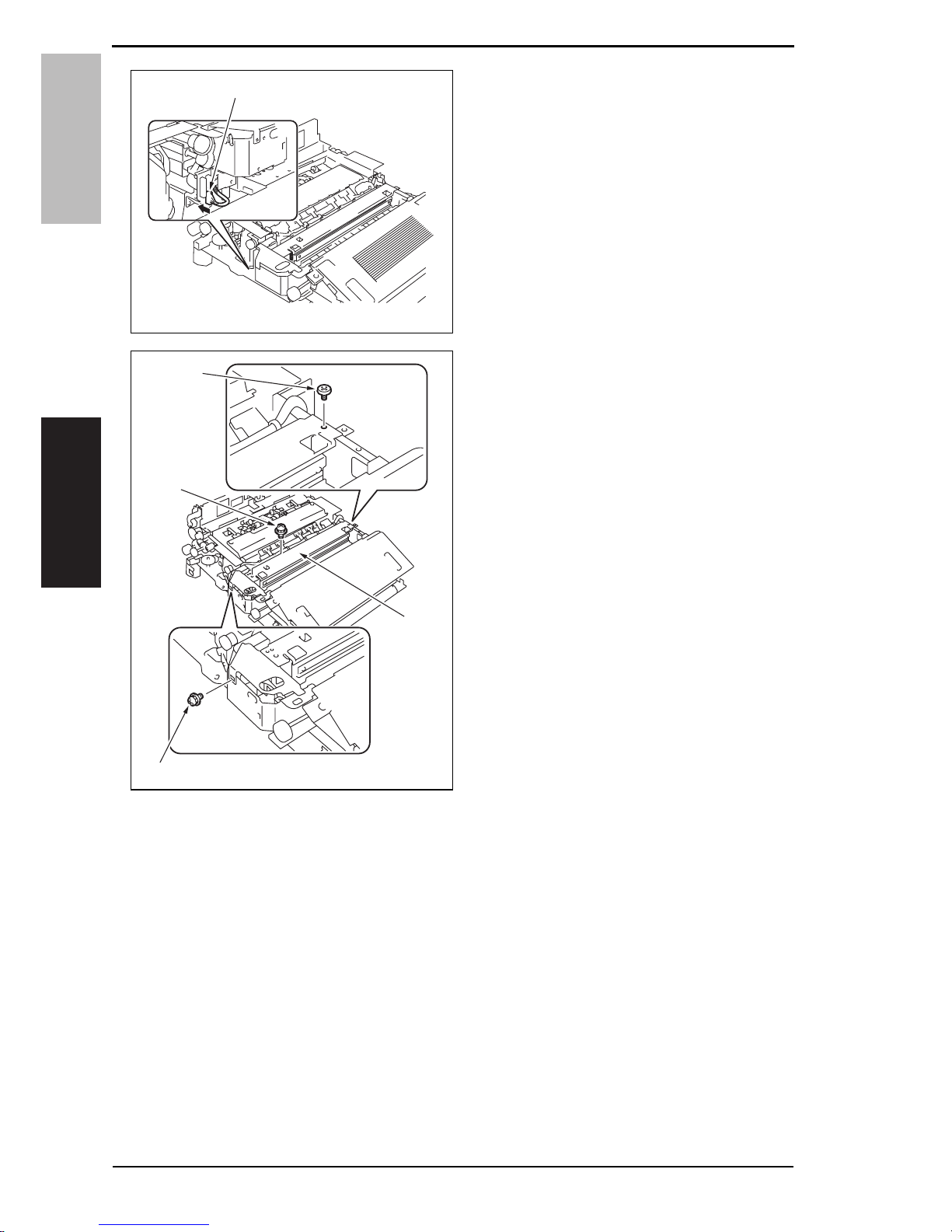
3.3.4 Saddle unit
1. Remove the screw [1], and remove
the connector cover [2].
2. Remove the screw [1], and remove
the ground wire [2].
3. Disconnect two connectors [3].
4. Remove the snap band [4].
5. Remove the screw [1], and remove
the mounting bracket [2].
4511F2C555DA
[2]
[1]
4511F2C556DA
[1]
[2]
[3] [4]
4511F2C557DA
[1]
[2]
Y108482-2 Service Manual
Page 12

3. Other Field Service Ver. 2.0 Jan. 2008
8
SD-505
Maintenance
6. Pull the lock release lever [1], and
open the saddle unit.
7. Remove the screw [2].
8. Remove two screws [1], and remove
the saddle unit [2].
4511F2C558DA
[2]
[1]
4511F2C559DA
[1]
[2]
Service Manual Y108482-2
Page 13

Field Service Ver. 2.0 Jan. 2008 3. Other
9
SD-505Maintenance
3.3.5 Crease unit
1. Remove the saddle unit.
See P.7
2. Remove the finisher unit.
See P.34 of the FS-519/PK-515/OT-602 service manual.
3. Remove four screws [1] and remove
the finisher unit rear cover [2].
4. Disconnect the connector [3].
5. Remove three screws [1] and
remove the finisher unit upper cover
[2].
6. Remove two screws [1] and remove
the finisher unit right front cover [2].
NOTE
• At reinstallation, first fit the tab [3]
into position.
4511F2C560DA
[3]
[1]
[2]
[1]
4511F2C561DA
[1]
[1]
[2]
4511F2C562DA
[2]
[3]
[1]
Y108482-2 Service Manual
Page 14
3. Other Field Service Ver. 2.0 Jan. 2008
10
SD-505
Maintenance
7. Disconnect the connector [1].
8. Remove three screws [1], and
remove the crease unit [2].
NOTE
• When the punch kit is mounted,
remove the punch kit first.
4511F2C563DA
[1]
4511F2C564DA
[1]
[1]
[1]
[2]
Service Manual Y108482-2
Page 15

Field Service Ver. 2.0 Jan. 2008 3. Other
11
SD-505Maintenance
3.3.6 Stapler unit
1. Remove the saddle unit.
See P.7
2. Remove the paper output tray.
See P.5
3. Remove the front cover.
See P.5
4. Remove the rear cover.
See P.6
5. Remove the upper cover.
See P.6
6. Remove the screw [1], and remove
the ground wire [2].
7. Remove two screws [3], and remove
the holder [4].
8. Release the lock release lever [1],
and slide the saddle unit mounting
plate [2].
9. Remove the shoulder screw [3] and
the washer [4], and remove the saddle unit mounting plate [2].
10. Remove the harness clamp [1] from
the metal bracket.
11. Remove the harness from the
wire
saddle.
12. Disconnect four connectors [1].
13. Remove the C-ring [2], and remove
the bearing [3].
14. Remove five screws [4], and remove
the drive unit [5].
4511F2C513DA
[1]
[2]
[3]
[3]
[4]
4511F2C515DA
[3]
[4]
[1]
[2]
4511F2C516DA
[1]
4511F2C517DA
[5]
[1]
[1]
[2]
[3]
[4]
[4]
Y108482-2 Service Manual
Page 16

3. Other Field Service Ver. 2.0 Jan. 2008
12
SD-505
Maintenance
15. Remove the wire saddle [1], and disconnect the connector [2].
16. Remove two screws [1] and two
shoulder screws [2].
17. Remove the processing tray [1].
18. Disconnect all the connectors on the
SD control board.
19. Remove the board support, and then
remove the SD control board [1].
20. Remove the screw [1], and remove
the lock release lever [2].
4511F2C518DA
[2]
[1]
4511F2C519DA
[1]
[2]
4511F2C520DA
[1]
4511F2C521DA
[1]
4511F2C522DA
[1]
[2]
Service Manual Y108482-2
Page 17

Field Service Ver. 2.0 Jan. 2008 3. Other
13
SD-505Maintenance
21. Remove eight screws [1], and
remove the lower cover [2].
22. Remove the wire saddle and disconnect the connector.
23. Remove three screws [1], and
remove the clincher 1 [2].
24. Remove the staple cartridge 1 [1].
25. Remove four screws [1], and remove
the stapler 1 [2].
NOTE
• To replace clincher 2 and stapler 2,
repeat steps 22 to 25.
4511F2C523DA
[2]
[1]
[1]
[1]
[1]
4511F2C524DA
[2]
[1]
4511F2C525DA
[1]
4511F2C526DA
[1]
[2]
Y108482-2 Service Manual
Page 18

3. Other Field Service Ver. 2.0 Jan. 2008
14
SD-505
Maintenance
Precaution for clincher reinstallation
• When the clincher is installed, the position of the stapler and the clincher will be
misaligned. Be sure to perform the following adjustment.
1. Use three screws [1] to temporary fix
the clincher [2].
2. Loosen the screw [1] of the stopper.
3. Loosen three screws [2] of the
clincher.
4. Aligning the protrusions of the jig [2]
with the recesses in the stapler [1], fit
the jig to the stapler.
NOTE
• Make sure that the protrusions of
the jig properly rest in the recesses.
5. Turn the gear [1] of the clincher and
then slide the clincher assy so that
the protrusion of the clincher [3] fits
into the recess in the jig [2].
4511F2C550DA
[2]
[1]
4511F2C551DA
[1]
[2]
4511F2C552DA
[2]
[1]
4511F2C553DA
[1]
[3]
[2]
Service Manual Y108482-2
Page 19

Field Service Ver. 2.0 Jan. 2008 3. Other
15
SD-505Maintenance
6. Tighten six screws [1].
NOTE
• Turn the gear again and check to
see that the protrusion of the
clincher smoothly fits into the
recess in the jig.
7. Turn the gear and remove the jig.
3.3.7 In & out guide motor
1. Remove the saddle unit.
See P.7
2. Remove the paper output tray.
See P.5
3. Remove the front cover.
See P.5
4. Remove the rear cover.
See P.6
5. Remove the upper cover.
See P.6
6. Remove the screw [1], and remove
the ground wire [2].
7. Remove two screws [3], and remove
the holder [4].
8. Release the lock release lever [1],
and slide the saddle unit mounting
plate [2].
9. Remove the shoulder screw [3] and
the washer [4], and remove the saddle unit mounting plate [2].
10. Remove the screw [1], and remove
the lock release lever [2].
4511F2C554DA
[1]
[1]
4511F2C513DA
[1]
[2]
[3]
[3]
[4]
4511F2C515DA
[3]
[4]
[1]
[2]
4511F2C522DA
[1]
[2]
Y108482-2 Service Manual
Page 20

3. Other Field Service Ver. 2.0 Jan. 2008
16
SD-505
Maintenance
11. Remove eight screws [1], and
remove the lower cover [2].
12. Remove the wire saddle [1], and disconnect two connectors [2].
13. Remove the screw [1], and remove
the in & out guide motor assy [2].
14. Remove two C-rings [1].
15. Remove two bushings [2], and
remove the clutch gear assy [3].
16. Remove two screws [1], and remove
the in & out guide motor [2].
4511F2C523DA
[2]
[1]
[1]
[1]
[1]
4511F2C529DA
[1]
[2]
4511F2C530DA
[1]
[2]
4511F2C531DA
[3]
[2]
[1]
4511F2C532DA
[1]
[1]
[2]
Service Manual Y108482-2
Page 21

Field Service Ver. 2.0 Jan. 2008 3. Other
17
SD-505Maintenance
Precaution for in & out guide motor reinstallation
1. Press the two in & out guides [1] in and check that they touch the stopper [2] simultaneously.
2. Check that pins [4] can be inserted through the positioning holes [3] (3 holes) of the in
& out guide sensor assy.
3. Use two screws to secure the in & out guide motor.
3.3.8 Crease roller
1. Remove the crease unit.
See P.9
2. Remove two springs [1] and four
screws [2], and remove the upper
plate [3].
4511F2C533DA
[1]
[2]
[3]
[4]
4511F2C565DA
[1]
[1]
[2]
[2]
[3]
Y108482-2 Service Manual
Page 22

3. Other Field Service Ver. 2.0 Jan. 2008
18
SD-505
Maintenance
3. Remove two screws [1], and remove
the guide plate [2].
4. Remove two screws [1], and remove
the chopper assy [2].
NOTE
• Install the chopper assy in the
direction shown in the left figure.
4511F2C566DA
[2]
[1]
4511F2C567DA
[1]
[1]
[2]
4511F2C583DA
Front Rear
Service Manual Y108482-2
Page 23

Field Service Ver. 2.0 Jan. 2008 3. Other
19
SD-505Maintenance
5. Remove three C-rings [1] and three
pins [2], and remove three gears [3].
NOTE
• Use care not to lose the pin.
NOTE
• Install the gear so that the mark [1]
is aligned to the position shown in
the left figure.
6. Remove two C-rings [1], and remove
two bearings [2].
7. Remove the bushing [3].
4511F2C568DA
[1]
[2]
[3]
[3]
4511F2C569DA
[1]
4511F2C570DA
[1]
[2]
[3]
Y108482-2 Service Manual
Page 24

3. Other Field Service Ver. 2.0 Jan. 2008
20
SD-505
Maintenance
8. Remove two screws [1], and remove
the rear holder [2].
9. Remove the C-ring [1] and the pin
[2], and remove the gear [3].
NOTE
• Use care not to lose the pin.
NOTE
• Install the gear so that the mark [1]
is aligned to the position shown in
the left figure.
4511F2C571DA
[1]
[2]
4511F2C572DA
[1]
[3]
[2]
4511F2C573DA
[1]
Service Manual Y108482-2
Page 25

Field Service Ver. 2.0 Jan. 2008 3. Other
21
SD-505Maintenance
10. Remove two C-rings [1], two bearings [2] and two washers [3].
NOTE
• Use care not to lose the washer.
11. Remove two gears [1] of crease
roller 1 assy, and remove the guide
plate [2].
NOTE
• When installing the gear [1] to the
guide plate [2], insert the gear [1] at
an angle and use care not to break
the tabs [3].
• Install the guide plate as shown on
the left.
4511F2C574DA
[1]
[2]
[3]
4511F2C581DA
[1]
[2]
4511F2C575DA
[1]
[2]
[3]
Long one
Y108482-2 Service Manual
Page 26

3. Other Field Service Ver. 2.0 Jan. 2008
22
SD-505
Maintenance
NOTE
• When mounting the crease roller 1
assy [1], mount it so that the tally
mark on the gear [2] for the crease
roller 1 and the tally mark on the
gear below will be next to each
other with the one on the gear [2]
being outer side.
12. Remove the screw [1].
13. Remove two C-rings [2] and remove
the crease roller A [3], B [4] and C
[5].
14. Remove two gears [1] of crease
roller 2 assy, and remove the guide
plate [2].
4511F2C576DA
[2]
[1]
4511F2C577DA
[1]
[2]
[2]
[5]
[4]
[3]
4511F2C582DB
[1]
[2]
Service Manual Y108482-2
Page 27

Field Service Ver. 2.0 Jan. 2008 3. Other
23
SD-505Maintenance
NOTE
• When installing the gear [1] to the
guide plate [2], insert the gear [1] at
an angle and use care not to break
the tabs [3].
• Install the gear and guide plate as
shown on the left.
15. Remove the screw [1].
16. Remove two C-rings [2] and remove
the crease roller A [3], B [4] and C
[5].
NOTE
• When mounting the crease roller
assy 2, mount it so that the gear [1]
for the crease roller 2 assy will be
over the gear for the cease roller 1
by one tooth.
4511F2C578DA
[1]
[3] [2]
D cutting
4511F2C577DA
[1]
[2]
[2]
[5]
[4]
[3]
4511F2C579DA
[1]
Y108482-2 Service Manual
Page 28

3. Other Field Service Ver. 2.0 Jan. 2008
24
SD-505
Maintenance
NOTE
• Use care to mount the crease roller
assy 1 [1] and 2 [2] in the proper
directions.
3.4 Cleaning procedure
NOTE
• The alcohol described in the cleaning procedure of maintenance represents the
isopropyl alcohol.
3.4.1 Cleaning of the rollers and rolls
1. Using a cleaning pad dampened with
alcohol, wipe the roller [1] and roll
[2].
2. Remove the crease unit.
See P.9
3. Using a cleaning pad dampened with
alcohol, wipe the roller [1].
4511F2C580DA
[1]
[2]
4511F2C502DA
[1]
[1]
[1]
[2]
[2]
[2]
4511F2C011DA
[1]
Service Manual Y108482-2
Page 29

Field Service Ver. 2.0 Jan. 2008 4. How to use the adjustment section
25
SD-505Adjustment / Setting
Adjustment/Setting
4. How to use the adjustment section
• “Adjustment/Setting” contains detailed information on the adjustment items and procedures for this machine.
• Throughout this “Adjustment/Setting,” the default settings are indicated by “ ”.
Advance checks
Before attempting to solve the customer problem, the following advance checks must be
made. Check to see if:
• The power supply voltage meets the specifications.
• The power supply is properly grounded.
• The machine shares the power supply with any other machine that draws large current
intermittently (e.g., elevator and air conditioner that generate electric noise).
• The installation site is environmentally appropriate: high temperature, high humidity,
direct sunlight, ventilation, etc.; levelness of the installation site.
• The original has a problem that may cause a defective image.
• The density is properly selected.
• The original glass, slit glass, or related part is dirty.
• Correct paper is being used for printing.
• The units, parts, and supplies used for printing (developer, PC drum, etc.) are properly
replenished and replaced when they reach the end of their useful serv
ice life.
• Toner is not running out.
CAUTION
• To unplug the power cord of the machine before starting the service job procedures.
• If it is unavoidably necessary to service the machine with its power turned ON, use
utmost care not to be caught in the scanner cables or gears of the exposure unit.
• Special care should be used when handling the fusing unit which can be
extremely hot.
• The developing unit has a strong magnetic field. Keep watches and measuring
instruments away from it.
• Take care not to damage the PC drum with a tool or similar device.
• Do not touch IC pins with bare hands.
Y108482-2 Service Manual
Page 30

5. Sensor check Field Service Ver. 2.0 Jan. 2008
26
SD-505
Adjustment / Setting
5. Sensor check
5.1 Check procedure
A. Procedure
1. Display the Service Mode screen.
See P.338 of the main body service manual.
2. Touch [State Confirmation].
3. Touch [Sensor Check].
4. Touch three times [z].
5.1.1 Sensor check screen
•This is only typical screen which may be different from what are shown on each individ-
ual main body.
4511F3E541DA
Service Manual Y108482-2
d-Color MF350 / d-Color MF250 / d-Color MF201Plus
d-Color MF450
4510F3E515DA
Page 31

Field Service Ver. 2.0 Jan. 2008 5. Sensor check
27
SD-505Adjustment / Setting
5.1.2 Sensor check list
A. Sensors 4
Symbol Panel display Part/Signal name
Operation characteris-
tics/Panel display
10
PS20
Sensors monitor4
Saddle exit Saddle exit sensor
Paper
present
Paper not
present
PS22 Folding R home Crease roller home position sensor
Paper
present
Paper not
present
SW5 Middle guide Middle guide switch Open Closed
PS24 Saddle guide Layable guide home sensor Blocked Unblocked
— Saddle stapler 1
— Home Staple Home Position Sensor 1 Blocked Unblocked
— Staple empty Staple Empty Detection Sensor 1 Blocked Unblocked
— Self priming Self-Priming Sensor 1 Blocked Unblocked
— Saddle stapler 2
— Home Staple Home Position Sensor 2 Blocked Unblocked
— Staple empty Staple Empty Detection Sensor 2 Blocked Unblocked
— Self priming Self-Priming Sensor 2 Blocked Unblocked
SW4 Saddle Saddle opening switch Open Closed
PS21 Saddle empty Saddle tray empty sensor
Paper
present
Paper not
present
PS18 Home (Saddle exit) Saddle exit roller home position sensor
Paper
present
Paper not
present
Y108482-2 Service Manual
Page 32

6. Finisher operations Field Service Ver. 2.0 Jan. 2008
28
SD-505
Adjustment / Setting
6. Finisher operations
6.1 Entering Finisher Check
1. Display the Service Mode screen.
See P.338 of the main body service manual.
2. Touch [Finisher].
3. Touch [CB-FN adjustment].
4. Touch [Finisher Check].
5. Touch the item one wants.
4511F3E533DA
Service Manual Y108482-2
Page 33

Field Service Ver. 2.0 Jan. 2008 6. Finisher operations
29
SD-505Adjustment / Setting
6.2 Finisher Check modes
A. Fold Drive
• Performs the creasing drive once.
o Raises the layable guide.
o Stops after the predetermined time.
o Lowers the layable guide.
o The operation is finished.
B. Saddle Outlet Open&Close
• Opens the saddle exit after the saddle exit is opened and closed.
o Stops after the predetermined time.
o The saddle exit closes.
o The saddle in & out guide advances.
o Stops after the predetermined time.
o The saddle in & out guide retracts.
o The operation is finished.
C. Conveyance Drive
• Transport drive is performed for the predetermined time. (Performs the same transport
drive as the pre-drive with the high speed of the connected copier.)
o Drives the entrance motor (M1).
o Drives the transport motor/1 (M2).
o Drives the transport motor/2 (M3).
o Drives the exit motor (M4).
o The operation is finished.
• If the mail bin kit MT-502 is installed, the mail bins are also driven.
• If the saddle kit SD-505 is also installed, the saddle transport motor (M8) is also driven.
Y108482-2 Service Manual
Page 34

6. Finisher operations Field Service Ver. 2.0 Jan. 2008
30
SD-505
Adjustment / Setting
6.3 Fold & Staple Pos. Adjustment
NOTE
Make this adjustment after any of the following procedures has been performed.
• When the crease unit has been replaced.
• When a deviation occurs in the crease.
• When fold angle adjustment has been made.
1. Make a copy in the crease mode. (A3 size)
2. Fold the copy fed out along the
crease.
3. Check the crease for deviation (Measure width A).
Specification: 0 ± 1.5 mm
4. When the width A does not fall within
the specified value, conduct the following adjustment.
5. Display the Service Mode screen.
See P.338 of the main body service manual.
6. Touch [Finisher].
7. Touch [CB-FN adjustment].
8. Touch [Fold & Staple Pos.Adjustment].
9. Touch [Fold Position Adjustment].
10. Touch [A3] and then touch [Normal Paper].
4511F3C505DA
A
Exit direction
4511F3E539DA
Service Manual Y108482-2
Page 35

Field Service Ver. 2.0 Jan. 2008 6. Finisher operations
31
SD-505Adjustment / Setting
• If the fold is offset as shown on the left.
11. Touch [-] and set the appropriate
numeric value.
Adjustment range: 0 to -10
(1 increment 0.5 mm)
• If the fold is offset as shown on the left.
12. Touch [+] and set the appropriate
numeric value.
Adjustment range: 0 to +10
(1 increment 0.5 mm)
13. Touch [END].
14. Make another copy, and check the deviation.
15. Touch [Exit] on the Service Mode screen.
16. Turn OFF the main power switch, wait for 10 sec., then turn the switch ON.
4511F3C505DA
A
Exit direction
4511F3C506DA
A
Exit direction
Y108482-2 Service Manual
Page 36

6. Finisher operations Field Service Ver. 2.0 Jan. 2008
32
SD-505
Adjustment / Setting
6.4 Center Staple Position Adjustment
NOTE
Make this adjustment after any of the following procedures has been performed.
• When staple unit has been replaced.
• When center staple position is misaligned.
• When center staple angle adjustment has been made.
1. Load a five-page A4 document in the
document feed tray.
2. Select the center staple mode and
make a copy. (A3 Size)
3. Check the staple position for deviation from the crease (Measure width
A).
Specification: 0 ± 1.5 mm
4. When the width A does not fall within
the specified value, conduct the following adjustment.
5. Display the Service Mode screen.
See P.338 of the main body service manual.
6. Touch [Finisher].
7. Touch [CB-FN adjustment].
8. Touch [Fold & Staple Pos.Adjustment].
9. Touch [Center Staple Position].
10. Touch [A3] and then touch [Normal Paper].
4511F3C510DA
A
Exit direction
4511F3E540DA
Service Manual Y108482-2
Page 37

Field Service Ver. 2.0 Jan. 2008 6. Finisher operations
33
SD-505Adjustment / Setting
• If the fold is offset as shown on the left.
11. Touch [-] and set the appropriate
numeric value.
Adjustment range: 0 to -10
(1 increment 0.5 mm)
• If the fold is offset as shown on the left.
12. Touch [+] and set the appropriate
numeric value.
Adjustment range: 0 to +10
(1 increment 0.5 mm)
13. Touch [END].
14. Make another copy, and check the deviation.
15. Touch [Exit] on the Service Mode screen.
16. Turn OFF the main power switch, wait for 10 sec., then turn the switch ON.
4511F3C510DA
A
Exit direction
4511F3C511DA
A
Exit direction
Y108482-2 Service Manual
Page 38

7. Mechanical adjustment Field Service Ver. 2.0 Jan. 2008
34
SD-505
Adjustment / Setting
7. Mechanical adjustment
7.1 Fold Angle Adjustment
NOTE
Make this adjustment after any of the following procedures has been performed.
• When the crease unit has been replaced.
• When a slant occurs in the crease.
1. Make a copy in the crease mode. (A3 size)
2. Fold the output paper along the
crease [1].
3. Fold the output paper and half and
measure the width A of the paper.
Specification: 0 ± 1.5 mm
4. If the fold position is slanted as
shown on the left, make the following
adjustment.
5. Open the front door, loosen the
adjustment screw [1], and move the
crease unit to the left to make the
adjustment.
Graduated in 1-mm divisions
• If the fold position is slanted opposite
to the figure of step 4, move the
crease unit to the right to make the
adjustment.
6. Make another copy and check the
fold position.
4511F3C501DA
[1]
A
Exit direction
Center
4511F3C532DA
[1]
Service Manual Y108482-2
Page 39

Field Service Ver. 2.0 Jan. 2008 7. Mechanical adjustment
35
SD-505Adjustment / Setting
7.2 Center Staple Angle Adjustment
NOTE
Make this adjustment after any of the following procedures has been performed.
• When staple unit has been replaced.
• When a slant occurs in the position of the center staple.
1. Load a five-page A4 document in the
document feed tray.
2. Select the center staple mode and
make a copy. (A3 Size)
3. Check the staple position for deviation from the crease (Measure width
A).
Specification: 0 ± 1.5 mm
4. If the staple position is slanted as
shown on the left, make the following
adjustment.
5. Release the lock release lever [1] of
the saddle unit.
6. Loosen the adjustment screw [2] and
move the lock lever to the left to
make the adjustment.
• If the staple position is slanted oppo-
site to the figure of step 2, move the
lock lever to the right to make the
adjustment.
7. Make another copy and check the staple position.
4511F3C507DA
Exit direction
A
4511F3C508DA
[2]
[1]
Y108482-2 Service Manual
Page 40

7. Mechanical adjustment Field Service Ver. 2.0 Jan. 2008
36
SD-505
Adjustment / Setting
Blank Page
Service Manual Y108482-2
Page 41

Field Service Ver. 2.0 Jan. 2008 8. Jam display
37
SD-505
Troubleshooting
Troubleshooting
8.Jam display for d-Color MF350 / MF250 / MF201Plus
8.1 Misfeed display
• When misfeed occurs, message, misfeed location “Blinking” and paper location “Lighting” are displayed on the touch panel of the main body.
8.2 Sensor layout
Display Code Misfeed location Misfeed processing location Action
[1]
7221 Paper bundle exit misfeed Front door P. 3 9
7285 Staple unit 1 misfeed Saddle cover
P. 4 0
7284 Staple unit 2 misfeed Saddle cover
7225 Creasing section misfeed Front door P. 4 1
4511F4C505DA
[1]
[1] Saddle exit sensor PS20
[2] Entrance sensor PS1
[3] Storage tray detect sensor PS3
4511F4C501DA
[1]
[3]
[2]
Y108482-2 Service Manual
Page 42

8. Jam display Field Service Ver. 2.0 Jan. 2008
38
SD-505
Troubleshooting
8.3 Solution
8.3.1 Initial check items
• When a paper misfeed occurs, first perform the following initial check items.
8.3.2 Solution when paper curl occurs
Check Item Action
Does the paper meet product specifications? Change the paper.
Is paper curled, wavy, or damp? See “Solution when paper curl occurs” on P.38.
Is a foreign object present along the paper path, or is
the paper path deformed or worn?
Clean or change the paper path.
Are the rolls/rollers dirty, deformed, or worn? Clean or change the defective roll/roller.
Are the edge guide and trailing edge stop at the correct position to accommodate the paper?
Set as necessary.
Are the actuators found operational when checked for
correct operation?
Correct or change the defective actuator.
Step Check items/actions
1 Turn over the stacked paper in the paper tray.
OK —
NG Go to step 2.
2
Does paper curl occur just after a warm-up has been completed or
the sleep mode has been turned OFF?
YES Go to step 3.
Does paper curl occur under normal conditions (under conditions
other than those mentioned above)?
YES Go to step 5.
3
1. Call the Service Mode to the screen.
2. Select [System 1] → [Change Warm Up Time].
3. Change the setting to [Mode3].
See P.394 of the main body service manual.
OK —
NG Go to step 4.
4
1. Call the Service Mode to the screen.
2. Select [System 1] → [Change Warm Up Time].
3. Change the setting to [Mode4].
See P.394 of the main body service manual.
——
5
1. Call the Service Mode to the screen.
2. Select [Machine] → [Fusing Temperature].
3. Select a paper type.
4. Change the temperature of Heater Roller to [-10 °C].
See P.346 of the main body service manual.
OK —
NG Go to step 6
6
1. Call the Ser
vice Mode to the screen.
2. Select [Machine] → [Fusing Temperature].
3. Select a paper type.
4. Change the temperature of Heater Roller to [-20 °C].
See P.346 of the main body service manual.
——
Service Manual Y108482-2
Page 43

Field Service Ver. 2.0 Jan. 2008 8. Jam display
39
SD-505
Troubleshooting
8.3.3 Paper bundle exit misfeed
A. Detection timing
B. Action
Type Description
Paper bundle misfeed
detection
The storage tray detecting sensor (PS3) is not turned OFF even after the
set period of time has elapsed after the exit motor (M4) is energized.
The saddle exit sensor (PS20) is not turned ON even after the set period of
time has elapsed after the exit motor (M4) is energized.
The saddle exit sensor (PS20) is not turned OFF even after the set period
of time has elapsed after the saddle exit sensor (PS20) is turned ON.
Relevant electrical parts
Storage tray detect sensor (PS3)
Saddle exit sensor (PS20)
Exit motor (M4)
Saddle exit motor (M8)
SD control board (SDCB)
Step Action
WIRING DIAGRAM
Control signal
Location
(Electrical
component)
1 Initial check items — —
2 PS3 I/O check, sensor check FSCB PJ14-8 (ON) FS-519 C-12
3 PS20 I/O check, sensor check SDCB PJ19-8 (ON) SD-505 B-2
4 M4 operation check FSCB PJ10-5 to 8 FS-519 C-3
5 M8 operation check SDCB PJ4-1 to 2 SD-505 G-6
6 Change SDCB — —
Y108482-2 Service Manual
Page 44

8. Jam display Field Service Ver. 2.0 Jan. 2008
40
SD-505
Troubleshooting
8.3.4 Staple unit 1 misfeed/Staple unit 2 misfeed
A. Detection timing
B. Action
Type Description
Staple unit misfeed
detection
The staple home position sensor in the staple unit is not turned ON even
after the set period of time has elapsed after the staple motor rotates forward, and then the staple motor rotates backward, and the staple home
position sensor in the staple unit is turned ON within the set period of time.
Relevant electrical parts
Staple unit 1
Staple unit 2
SD control board (SDCB)
Step Action
WIRING DIAGRAM
Control signal
Location
(Electrical
component)
1 Initial check items — —
2 Drive coupling section check — —
3 Sensor check — —
4 Change staple unit 1 — —
5 Change staple unit 2 — —
6 Change SDCB — —
Service Manual Y108482-2
Page 45

Field Service Ver. 2.0 Jan. 2008 8. Jam display
41
SD-505
Troubleshooting
8.3.5 Creasing section misfeed
A. Detection timing
B. Action
Type Description
Creasing section
misfeed detection
The entrance sensor (PS1) is not turned ON even after the set period of
time has elapsed after the entrance motor (M1) is energized (beginning of
backward rotation operation).
The entrance sensor (PS1) is not turned OFF even after the set period of
time has elapsed after the entrance motor (M1) is energized (beginning of
forward rotation operation).
Relevant electrical parts
Entrance sensor (PS1)
Entrance motor (M1)
SD control board (SDCB)
Step Action
WIRING DIAGRAM
Control signal
Location
(Electrical
component)
1 Initial check items — —
2 PS1 I/O check, sensor check FSCB PJ19-11 (ON) FS-519 C-7
3 M1 operation check FSCB PJ9-1 to 4 FS-519 C-6 to 7
4 Change SDCB — —
Y108482-2 Service Manual
Page 46

1. Product specification Field Service Ver. 2.0 Jan. 2008
42
SD-505
Blank Page
Service Manual Y108482-2
Troubleshooting
Page 47

Field Service Ver. 2.0 Jan. 20089. Jam display
43
SD-505
Troubleshooting
Troubleshooting
9.Jam display for d-Color MF450
9.1 Misfeed display
• When misfeed occurs, message, misfeed location “Blinking” and paper location “Lighting” are displayed on the touch panel of the main unit.
9.2 Sensor layout
Display Code Misfeed location Misfeed processing location Action
[1]
7221
Paper bundle exit misfeedFront doorP.45
7285
Staple unit 1 misfeed Saddle cover
P.46
7284
Staple unit 2 misfeed Saddle cover
7225
Creasing section misfeedFront doorP.47
4511F4C504DA
[1]
[1] Saddle exit sensor PS20
[2] Entrance sensor PS1
[3] Storage tray detect sensor PS3
4511F4C501DA
[1]
[3]
[2]
Y108482-2 Service Manual
Page 48

9. Jam displayField Service Ver. 2.0 Jan. 2008
44
SD-505
Troubleshooting
9.3 Solution
9.3.1 Initial check items
• When a paper misfeed occurs, first perform the following initial check items.
Check Item Action
Does the paper meet product specifications? Change the paper.
Is paper curled, wavy, or damp?
Change the paper.
Instruct the user in correct paper storage.
Is a foreign object present along the paper path, or is the
paper path deformed or worn?
Clean or change the paper path.
Are the rolls/rollers dirty, deformed, or worn? Clean or change the defective roll/roller.
Are the edge guide and trailing edge stop at the correct
position to accommodate the paper?
Set as necessary.
Are the actuators found operational when checked for
correct operation?
Correct or change the defective actuator.
Service Manual Y108482-2
Page 49

Field Service Ver. 2.0 Jan. 20089. Jam display
45
SD-505
Troubleshooting
9.3.2 Paper bundle exit misfeed
A. Detection timing
B. Action
Type Description
Paper bundle misfeed
detection
The storage tray detecting sensor (PS3) is not turned OFF even after the
set period of time has elapsed after the exit motor (M4) is energized.
The saddle exit sensor (PS20) is not turned ON even after the set period of
time has elapsed after the exit motor (M4) is energized.
The saddle exit sensor (PS20) is not turned OFF even after the set period
of time has elapsed after the saddle exit sensor (PS20) is turned ON.
Relevant electrical parts
Storage tray detect sensor (PS3)
Saddle exit sensor (PS20)
Exit motor (M4)
Saddle exit motor (M8)
SD control board (SDCB)
Step Action
WIRING DIAGRAM
Control signal
Location
(Electrical
component)
1 Initial check items — —
2 PS3 sensor check FSCB PJ14FSCB-8 (ON) FS-519 C-12
3 PS20 sensor check SDCB PJ19SDCB-8 (ON) SD-505 B-2
4 M4 operation check FSCB PJ10FSCB-5 to 8 FS-519 C-3
5 M8 operation check SDCB PJ4SDCB-1 to 2 SD-505 G-6
6 Change SDCB — —
Y108482-2 Service Manual
Page 50

9. Jam displayField Service Ver. 2.0 Jan. 2008
46
SD-505
Troubleshooting
9.3.3 Staple unit 1 misfeed/Staple unit 2 misfeed
A. Detection timing
B. Action
Type Description
Staple unit misfeed
detection
The staple home position sensor in the staple unit is not turned ON even
after the set period of time has elapsed after the staple motor rotates forward, and then the staple motor rotates backward, and the staple home
position sensor in the staple unit is turned ON within the set period of time.
Relevant electrical parts
Staple unit 1
Staple unit 2
SD control board (SDCB)
Step Action
WIRING DIAGRAM
Control signal
Location
(Electrical
component)
1 Initial check items — —
2 Drive coupling section check — —
3 Sensor check — —
4 Change staple unit 1 — —
5 Change staple unit 2 — —
6 Change SDCB — —
Service Manual Y108482-2
Page 51

Field Service Ver. 2.0 Jan. 20089. Jam display
47
SD-505
Troubleshooting
9.3.4 Creasing section misfeed
A. Detection timing
B. Action
Type Description
Creasing section
misfeed detection
The entrance sensor (PS1) is not turned ON even after the set period of
time has elapsed after the entrance motor (M1) is energized (beginning of
backward rotation operation).
The entrance sensor (PS1) is not turned OFF even after the set period of
time has elapsed after the entrance motor (M1) is energized (beginning of
forward rotation operation).
Relevant electrical parts
Entrance sensor (PS1)
Entrance motor (M1)
SD control board (SDCB)
Step Action
WIRING DIAGRAM
Control signal
Location
(Electrical
component)
1 Initial check items — —
2 PS1 sensor check FSCB PJ19FSCB-11 (ON) FS-519 C-7
3 M1 operation check FSCB PJ9FSCB-1 to 4 FS-519 C-6 to 7
4 Change SDCB — —
Y108482-2 Service Manual
Page 52

10. Malfunction code Field ServiceVer. 2.0 Jan. 2008
48
SD-505
Troubleshooting
10.Malfunction code
10.1Trouble code
• The machine’s CPU performs a self-diagnostics function that, on detecting a malfunction,
gives the corresponding malfunction code and maintenance call mark on the touch
panel.
Code Item Description
C11A2
Saddle exit roller
pressure/retraction
failure
• The saddle exit roller home position sensor (PS18) is not
turned ON even after the set period of time has elapsed after
the saddle exit open/close motor (M9) is energized (beginning
of pressure operation).
• The saddle exit roller home position sensor (PS18) is not
turned OFF even after the set period of time has elapsed after
the saddle exit open/close motor (M9) is energized (beginning
of retraction operation).
C11A4 Saddle exit motor failure
The lock signal is detected after the set period of time has
elapsed after the saddle exit motor (M8) is energized.
C11A5
Saddle in & out guide
motor failure
• The in & out guide home sensor (PS23) is not turned OFF
even after the set period of time has elapsed after the in & out
guide motor (M13) is energized (beginning of advancing operation).
• The in & out guide home sensor (PS23) is not turned ON even
after the set period of time has elapsed after the in & out
guide motor (M13) is energized (beginning of retracting operation).
C11A6
Saddle layable guide drive
failure
• The layable guide home sensor (PS24) is not turned ON even
after the set period of time has elapsed after the layable guide
motor (M14) is energized (beginning of return operation to
predetermined position).
• The layable guide home sensor (PS24) is not turned OFF
even after the set period of time has elapsed after the layable
guide motor (M14) is energized (beginning of return operation
to predetermined position).
C11B5
Side staple 1 drive
failure
Home position sensor 1 is not turned OFF even after the set
period of time has elapsed after saddle staple motor 1 is energized (beginning of staple operation).
C11B6
Side staple 2 drive
failure
Home position sensor 2 is not turned OFF even after the set
period of time has elapsed after saddle staple motor 2 is energized (beginning of staple operation).
C11D0
Crease motor drive
failure
• The crease roller home position sensor (PS22) is not turned
OFF even after the set period of time has elapsed after the
crease motor (M10) is energized (beginning of backward rotation operation).
• The crease roller home position sensor (PS22) is not turned
ON even after the set period of time has elapsed after the
crease motor (M10) is energized (beginning of forward rotation operation).
Service Manual Y108482-2
Page 53

Field Service Ver. 2.0 Jan. 2008 10. Malfunction code
49
SD-505
Troubleshooting
10.2Solution
10.2.1C11A2: Saddle exit roller pressure/retraction failure
10.2.2C11A4: Saddle exit motor failure
Relevant electrical parts
Saddle exit open/close motor (M9)
Saddle exit roller home position sensor (PS18)
SD control board (SDCB)
Step Action
WIRING DIAGRAM
Control signal
Location
(Electrical
component)
1
Check the M9 connector for proper connection and correct as necessary.
——
2
Check M9 for proper drive coupling and
correct as necessary.
——
3 M9 operation check SDCB PJ4-6 to 7 SD-505 G-5 to 6
4 PS18 I/O check, sensor check SDCB PJ9-6 (ON) SD-505 B-2
5 Change SDCB — —
Relevant electrical parts
Saddle exit motor (M8) SD control board (SDCB)
Step Action
WIRING DIAGRAM
Control signal
Location
(Electrical
component)
1
Check the M8 connector for proper connection and correct as necessary.
——
2
Check M8 for proper drive coupling and
correct as necessary.
——
3 M8 operation check SDCB PJ4-1 to 2 SD-505 G-6
4 Change SDCB — —
Y108482-2 Service Manual
Page 54

1
50
SD-505
Troubleshooting
10.2.3C11A5: Saddle in & out guide motor failure
10.2.4C11A6: Saddle layable guide drive failure
Relevant electrical parts
In & out guide motor (M13)
In & out guide home sensor (PS23)
SD control board (SDCB)
Step Action
WIRING DIAGRAM
Control signal
Location
(Electrical
component)
1
Check the M13 connector for proper connection and correct as necessary.
——
2
Check M13 for proper drive coupling and
correct as necessary.
——
3 M13 operation check SDCB PJ4-4 to 5 SD-505 G-6
4 PS23 I/O check, sensor check SDCB PJ10-3 (ON) SD-505 B-2 to 3
5 Change SDCB — —
Relevant electrical parts
Layable guide motor (M14)
Layable guide home sensor (PS24)
SD control board (SDCB)
Step Action
WIRING DIAGRAM
Control signal
Location
(Electrical
component)
1
Check the M14 connector for proper connection and correct as necessary.
——
2
Check M14 for proper drive coupling and
correct as necessary.
——
3 M14 operation check SDCB PJ4-8 to 9 SD-505 G-5
4 PS24 I/O check, sensor check SDCB PJ10-6 (ON) SD-505 B-3
5 Change SDCB — —
Service Manual Y108482-2
10. Malfunction code Field ServiceVer. 2.0 Jan. 2008
Page 55

51
SD-505
Troubleshooting
10.2.5C11B5: Side staple 1 drive failure
10.2.6C11B6: Side staple 2 drive failure
10.2.7C11D0: Crease motor drive failure
Relevant electrical parts
Staple unit 1
Staple unit 2
SD control board (SDCB)
Step Action
WIRING DIAGRAM
Control signal
Location
(Electrical
component)
1
Check the staple units 1 and 2 connectors
for proper connection and correct as necessary.
——
2
Check staple units 1 and 2 for proper drive
coupling, and correct as necessary.
——
3 Staple units 1 and 2 operation check — —
4 Change staple units 1 and 2 — —
5 Change SDCB — —
Relevant electrical parts
Crease motor (M10)
Crease roller home position sensor (PS22)
SD control board (SDCB)
Step Action
WIRING DIAGRAM
Control signal
Location
(Electrical
component)
1
Check the M10 connector for proper connection and correct as necessary.
——
2
Check M10 for proper drive coupling and
correct as necessary.
——
3 M10 operation check SDCB PJ3-1 to 2 SD-505 C-7
4 PS22 I/O check, sensor check SDCB PJ2-3 (ON) SD-505 C-7
5 Change SDCB — —
Y108482-2 Service Manual
Field Service Ver. 2.0 Jan. 2008 10. Malfunction code
Page 56

52
SD-505
Troubleshooting
Blank Page
Service Manual Y108482-2
10. Malfunction code Field ServiceVer. 2.0 Jan. 2008
Page 57

UPDATING STATUS
DATE UPDATED PAGES PAGES CODE
10/2008 1ST EDITION 57 Y108482-2
 Loading...