

Page 1
CHARACTERISTICS
Personal Com puter - Pocket Service G uide
M290-25
Microproc esso r INTEL 80286
Clock 20 MHz
Architect ure XT/AT with 32-bit addes sing
Memo ry From 1 MB t o 17 MB on t he m ot her bo ard
Banks 0 & 1 1 MB, two 256 KB x 18 bit
memory chips solder ed
Bank 2 On memory ex pans ion boar d.
2 sockets in which SIMM
modules can be insta lled :
1 M x 9 EXM 25-532 (2 MB)
4 M x 9 EXM 26-809 (8 MB)
Bank 3 Same as bank 2
Memory access 80 ns
Coprocessor 20 MHz 80287
Floppy Disk 1.2 MB 5.25" Panasonic JU 475- 3 C20
1.2 MB 5,25" Panasonic JU 47 5- 4 C20
1.44 MB 3,5" Panasonic JU2 57 A 293
1.44 MB 3,5" Panasonic JU2 57 A 294
1.44 MB 3,5" Sony MP-F17W - 86
1.44 MB 3,5" YE DATA YD-702B-604 9 B
Hard Disk 40 MB QUANTUM LPS 52 AT
40 MB W.D. AC 140
40 MB CONNER CP3044
40 MB CONNER CP3046F
40 MB QUANTUM Pioneer ELS42 AT
85 MB W.D. Caviar 280
85 MB CONNER CP30084E
85 MB QUANTUM Pioneer ELS85 AT
120 MB CONNER CP30126
120 MB W.D. AC 2120
120 MB QUANTUM Pioneer ELS 127 A T
Streaming Ta pe 120 MB STU 38-120 with floppy int er fa ce
Slots Three 16-bit conne ctor s on the expansion
BUS board
Video adapter VGA-comp atib le integ rate d on mother bo ar d
HDU and FDU con-
troller
Mouse PS/2- and AT-compatible
Keyboard 101/102-key ANK 26-101, ANK 26- 102
Integrat ed on mot her boa rd
Floppy disk controller : Nat ional
Hard disk interface : MSI buf fer s and logic
gates
MOTHERBOARD
BA 08 1 MB
BIOS
Latest level:
Rev. 2.01
EXPANSION BUS
-
POWER SUPPLY
220 V
MOUSE AND
KEYBOARD BOARD
-
MEMORY
EXPANSION BOAR D
-
HDU LED BOAR D
M203
32
M290-2 5 32-1
Page 2

Personal Comp ut er - Pock et Se rv ice G uide
MOTHERBOARD
LEVEL D.R.S.
ROM BIO S NOTES
CODE
Nasc.
Lev. 01
612558T Rev. 1.04
Rev. 2. 00
Mother boar d with 1 MB memo ry .
New topcat chip set (82C32 0A - 82C331A) . This
implies the addition of a 2 KOhm 1/4 W pull-u p
BA-08
Lev. 02
Rev. 2. 01
resistor R301 at location U 27, between CPU pins
5 and 62.
- New BIOS to solve the f ollowing problem s :
- Video controller WD90 C11 has been replac ed
Lev. 03
Rev. 2. 01
The new WD90C11- LR video co ntro ller replace s
the WD90C11.
Lev. 04
Rev. 2. 01
The new ICS90C61 VGA clock gen erat or replaces
the WD90C61.
KEYBOARD AND MOUSE INTERFACE BOARD
- Random system crashes
- No system bootstrapping
- Incorrect management of the S-RAM board
and of the A20 GATE signa l
- New hard disk table
by the equivalent contro ller WD90C11A- LR.
LEVEL D.R.S.
NOTES
CODE
Nasc. 731143V Integrating: Lithium batteries
Interface conn ect or s for keyboar d and mo u se
CMOS RAM
LED HARD DISK BOARD
LEVEL D.R.S.
NOTES
CODE
Nasc.
Lev. 02
M203
059135X
The DIODE has been re placed
32-2 M290-25
Page 3

Personal Com puter - Pocket Service G uide
MOTHERBO ARD INTEGRATED CONTROLLERS
MOTHERBOARD INTEGRATED CONTROL LERS
BA-08 80286 CPU 20 MHz microprocesso r
Soket for i387SX numeric coprocessor
8042 Keyboard and mo use co ntro ller
WD90C11 V.G.A. video controller
87C310 Serial and parallel port contro ller
NATIONAL Floppy disk controller
MSI buffer Intelligent har d disk inter fa ce
27C010 BIOS Eprom
TOPCAT System co nt roller 82C320
BUS controller 82C331
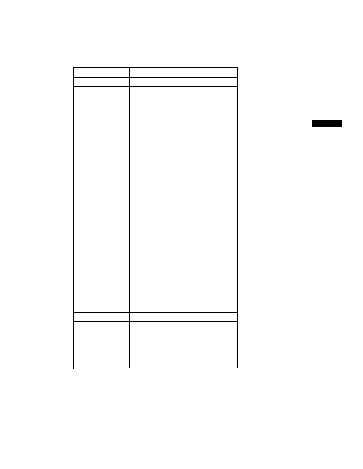
BOARDS
FUNCTION DESCRIPTION D.R.S. CODE CHARACTERISTICS
CPU sytem board
220 V Power supply
BUS Adapter board
Memory expansion board
Keyboard and mouse boar d
Hard disk LED board
BA-08 413251T
413079S
029231Z
059189E
030055Z
059135X
1 MB
USER DISKETTE
LEVEL COMPATIBILITY
Rel. 1.89 -
SYSTEM TEST
LEVEL COMPATIBILITY
Rev. 2.06 -
POWER SUPPLY UNIT
POWER SUPPLY LEVEL DESCRIPTION
220 V Nasc.
Lev. 03 With this level the power supply was ma de to comply wit h
Danish norms.
32
COMP ATIBILITY NO T E S
BOARD OR HW/SW
DESCRIPTION
DEVICE
--
SOFTWARE DRIVERS
DRIVER NOTES
EMS/LIM Ver. 4.0 For extended and expa nded mem ory manag em ent .
M290-2 5 32-3
Page 4

Personal Comp ut er - Pock et Se rv ice G uide
BIOS
LEVEL NOTES
Rev. 2. 00
-
Rev. 2. 01
SOFTWARE COM PATI BIL ITY
OPERATING SYSTEMS NOTES
IBM DISK O perating System, Ver. 3. 3 0
MS-DOS (Compaq)
IBM DISK O perating System, Ver. 4. 0 1
IBM Operat ing Sys te m/2 , Ver. 1.10 and 1.2 0
IBM Oper at ing System/2 Extended Edition,
Ver. 1.10 an d 1.20
INTERACTIVE 38 6/ ix, Ver. 2.0 2
SCO UNIX System V/386, Rev. 3.2
SCO XENIX 386, Rev. 2.3
WINDOWS
GEM/3 Desktop, IBM-PC Ver. 3.02
MS-WINDOWS /286 Ver. 2.11
This rele ase so lves t he f ol low ing:
- Random system crashes
- No system bootstrapping
- Incorrect manage m ent of the S-RO M boa rd and of the A 20 GATE signal.
- New hard disk table
A formatted DSDD disket te is requir ed
during insta llation on har d disk
The PS/2 mouse is not acknowledged
The PS/2 mouse is not acknowledged
MS-WINDOWS /386 Ver. 2.11
MS-W I ND O WS 3 Ve r . 3. 0
32-4 M290-25
Page 5

Personal Com puter - Pocket Service G uide
HARDWARE COMPATIBI LITY
MODEMS I/P INTERFACE PRODUCTS
Hayes Smart modem 2400B
FAXY PC MAXTER
IBM PRINTER ADAPTER (1505200)
STB 4-ON THE FLOOR
FURY 2400 PC MODEM
AT&T 2224 CEO MODEM
FURY 2400 MAXTER MODEM
FURY 2400 TI/MNP
Hayes Smart modem 120 0 B
MULTIPORT MOUSE
CHASE AT8
COMPUTONE AT 8
COMPUTONE AT 16
INTEL Bell ICC.6
SPECIALIX SI / 8
IBM PS/2 Mouse (64503 50)
IBM PS/2 Mous e Serial
Logitech Bus Mouse (PF-3F)
Logitech 3 button mouse
MS-BUS mouse
MS-MOUSE serial
GRAPHIC PRODUCTS NETWORK & LAN PRODUCTS
AST VGA plus
FASTWRITE 1024i
FASTWRITE VGA
HERCULES GRAPHICS CARD
IBM VGA Adapter
MATROX PG - 1281
MAXON MVGA- 16 Adap ter
ORCHID PRODESIGNER VG A PLUS
HERCULES INCOLOR CARD (GB222)
PARADISE VGA PRO CARD
10 NET INTERFACE BOARD 200 series
3COM Etherlink adapter 3C501
3COM Etherlink II adap te r 3C5 03
3COM Etherlink plus adapte r 3C505
3COM Etherlink plus adapte r 3C505
DECNET PCSA adapter
IBM PC NETWORK adapter II
IBM TOKEN RING 16/ 4 adapter
IBM TOKEN RING adapter II
MADGE AT RING NODE adapter
MICOM NP1000 adapter
NOVELL NE1000 adapter
NOVELL NE2000 adapter
DISPLAY UNITS
IBM enhanced g ra phics m onitor 5151
IBM color graphics monitor 5153
IBM PS/2 Monoch rom e display 8503
IBM PS/2 color d isplay 8512
IBM PS/2 color d isplay 8513
IBM PS/2 color d isplay 8514
NEC MULTISYNC 2A
NEC MULTISYNC 3D
NEC MULTISYNC 4D
NEC MULTISYNC 5D
PHILIPS 7BM7 49
PHILIPS 9CM0 82
NEC MULTISYNC II
32
M290-2 5 32-5
Page 6

KEYBOARD
AND
MOUSE
BOARD
CONN.
3rd FLOPPY
PERIPHERAL
CONN.
AMD3A
Personal Comp ut er - Pock et Se rv ice G uide
COMPONENTS AND JUM PERS ON THE SYSTEM BO AR D
VIDEO CONN. SERIAL CONN.PARALLEL CONN.
WD90C11
SOCKETS
FOR VIDEO
RAM
P
EXPAN-
SION
SOCKET
FOR
BUS
CONN.
80287
TOPCAT CHIPSET
CPU
80286
RAM BOARD CONN.
ROM BIO S
JUMPER P Position 1-2 Normal operation
Position 2-3 Erases the password
COMPONENTS AND JUMPERS OF THE KEYBOARD AND M OUSE BO ARD
FLOPPY
DISK
CONN.
POWER
SUPPLY CONN.
CHARACTER
GENERATOR
HDU LED
KEY
P1 inserted: Battery enable d, dat a presen t in CMOS RAM
P1 not inserted: Battery disabled, no data in the CMOS RAM
32-6 M290-25
LITHIUM
BATTERY
P1
MOUSE
CONNECTOR
KEYBOARD
CONNECTOR
ANG1A
Page 7
Personal Com puter - Pocket Service G uide
BUILT IN SETUP and EXTENDE D SETUP Utiliti es
BUILT IN SETUP
This progr am, resident in RO M BIOS, allows user s t o change so m e of the Personal Com p u ter co nfiguration pa ram et ers.
There are two possibilities:
First case: If the info rma tion in the CMO S RAM is no longer valid or if the power batter y is not charg ing, the screen wi ll display the BUILT IN SETUP. User s can select the national langu age ve rs io n
they wish to work in from a choice of 6 languages.
Second case: If the syst em configur at ion ha s been modified , on ly the icon of the device t o be
added or change d in the CMOS RAM w ill be displa yed. For instanc e, after installing a second
floppy disk the floppy disk icon w ill be displayed.
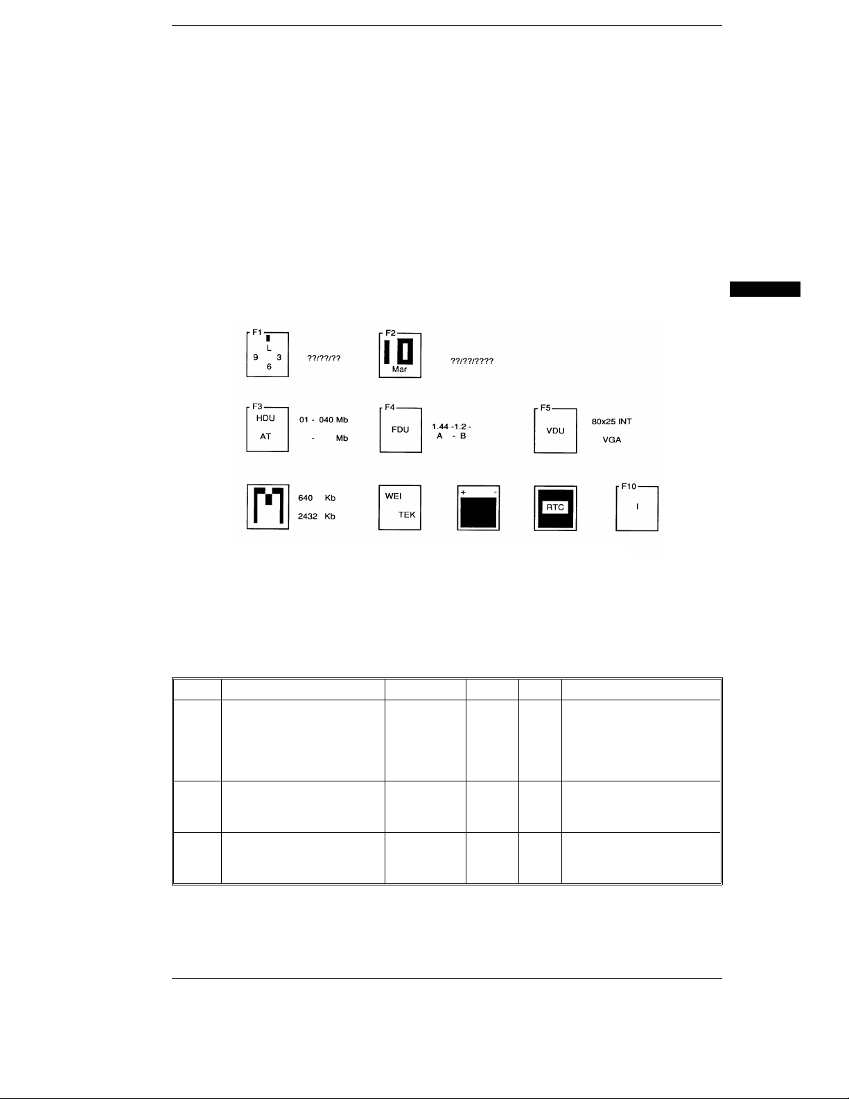
In both cases, this BUI LT IN SETUP s creen will be displayed automatically, without any operat or action.
32
F1 To modify hour, minutes and seconds.
F2 To modify day, month and year.
F3 Press this key to select hard disk type and cap acit y. Press th e space bar unt i l the correc t valu e is
displayed. The following table lists the har d disks tha t can be installed in th is system .
TYPE MODEL CAPACITY CYL T SECTORS PER TRACK
01
02 *
02
04 *
03
06*
Where: T: No. of heads
W.D. AC 140
QUANTUM LPS 52 AT
CONNER CP 3044
CONNER CP 3046F
QUANTUM ELS42 AT
W.D. CAVIAR AC 280
CONNER CP 30084E
QUANTUM ELS85 AT
W.D. AC-2120
CONNER CP 30126
QUANTUM ELS127 AT
CYL: No. of cylinders
(*) With B IOS 2.01
40 MB 980 5 17
85 MB 977 10 17
120 MB 762 8 39
M290-2 5 32-7
Page 8

Personal Comp ut er - Pock et Se rv ice G uide
F4 Press this key to select cap acit y of the floppy disk. Thr ee fields will be displayed beside the icon,
according to the num ber of drive s (1, 2 or 3) in the system ; ent er the capa city of the floppy disk
installed in the co rres pond in g field.
The line undern eat h sho ws th e letter s A (fo r one driv e only) , A - B (for two drive s) or
A - B - X (for three drives) . Thes e are th e logic nam es of the drives .
NOTE: To install a floppy interface str eam ing tap e, the data field cor resp onding to this
unit must not con tain any value and t he drive m ust have lo gic nam e B associat ed
with it.
F5 Press this key to select video format when the system is switc hed on .
Memory The inform at ion in this field ca nnot be ch ange d since it s only purpo se is to
inform the user of system mem or y ca pacity. The System or Cu stomer
Test diskette will be needed if you wish to change syst em m emory size.
Numeric coprocess or This icon is displayed only when the W EIT EK coprocessor is insta lled and
is for the informat ion of the user only.
Batteries This icon is displayed only when t he sys tem is switche d on for the
first time or whe n the syst em ba tt er ies ar e no t charging.
Real time clock This icon blinks when there is a fai lure of the syst em’s
Real Time Clock
Language It is possible to select th e langua ge in which to have the messag es of
the BUILT IN SETUP dis played . Ther e are six la ngua ges to cho ose f rom .
.
32-8 M290-25
Page 9

Personal Com puter - Pocket Service G uide
EXTENDED BUILT IN SETUP
In addition to the BUILT IN SETUP utility, there is another utility called EXTENDED BUILT IN
SETUP with which othe r pa ram et er s of the system can be configur ed. This utility can be called by
the operator by pressing the keys SHIFT , CTRL, ALT and DEL at the same time.
32
Exit
ESC
Select
RestartConfirm
CR
Messages
Press
This menu includes all icons of the BUILT IN SETUP and allows the sy st em to be configur ed as
described previously.
The follow ing ot her conf igur ation p a ram et er s have been ad ded:
F6 EMS Used to modify capacity of the extend ed m emor y and mem or y expansion .
TEST Used to reduce the numb er of tests mad e on the system memor y during the
power-on diagnostics.
SHAD Used to assign a quantity of shadow m em ory t o the BI OS and specific areas of
memory.
F7 RAM Used to mod ify syst em speed from the de fault va lu e of (33 MHz ) to
14 MH.,
I/O Used to modify the syst em BUS speed from the defau lt value of 11 MHz to
the AT standard spee d of 8 MHz.
F8 CHR/S Used to modify character repeat speed when the assoc iate d keys are
pressed. This key repeat value is exp re ssed as a numbe r of chara ct er s per
second.
BEEP Used to increase or decr ea se speaker volume.
PARAL Used to change direction of the parallel port.
F9 The system allows the user to enter a PASSWORD.
M290-2 5 32-9
Page 10

Personal Comp ut er - Pock et Se rv ice G uide
INTERRUPT LEVELS
LEVEL NAME CONTROLLER FUNCTION
1
2
3
4
5
6
7
8
9
10
11
12
13
14
15
16
NMI
IRQ0
IRQ1
RQ8
IRQ9
IRQ10
IRQ11
IRQ12
IRQ13
IRQ14
IRQ15
IRQ3
IRQ4
IRQ5
IRQ6
IRQ7
1
1
2
2
2
2
2
2
2
2
2
1
1
1
1
Parit y er ror
Channel 0 tim er OUT
Keyboard
Real time clock
Software redir ected to INT 0AH (IRQ2 )
Available
Available
Mouse
Available
Hard Disk controller
Available
Serial port 2
Serial port 1
Parallel port 2
Floppy Disk cont ro ller
Parallel port 1
I/O ADDRESS MAP
ADDRESS FUNCTION ADDRESS FUNCTION
000-00F DMA controller 1 2B0-2DF h Video control regist er s
020-02F h Interrupt controller 1 2E1 h Reserved
040-05F h Timer 2E2 h & 2E3 h Reserved
060 h Keyboard data contr oller 3 F8- 2FF h COM2 serial port
061 System control port B 300-31F h Reserved
064 h Keyboard comm and s cont roller 360-363 h Part low of the address
070 - 07F Real time clock, NMI, CMOS RAM 364-367 h Reserved
080-09F h DMA page regist er s 368-36B h Part high of the add ress
0A0-0AF h Interrupt controller 2 36C-36F h Reser ved
0E8-0EF h I/O control register s 378-37F h Parallel port 1 (LPT1)
0F0 h Cancels math coproces sor
operat ion
380-38F h SDLC (Synchronous Dat a Link
Control )
0F1 Resets the math cop rocess or 3A0-3AF h SDLC (Synchronous Data Link
Control
0A8-0FF h Math coprocessor 3B0- 3BF h Video control registers
1F0-1FF h Hard disk drive 3C0-3CF h Vide o contr ol re gist ers
200-20F Game port 3D0-3DF h Vide o contr ol re gist ers
21F h Audio commun icat ions ada pt er 3F0-3F7 Hard dis k contr oller
278-27F h Parallel port 2 (LPT2) 3F8- 3FF Serial port 1 (COM1)
32-10 M290-25
Page 11

Personal Com puter - Pocket Service G uide
SYSTEM MEMORY MAP
ADDRESS FUNCTION
000000 - 0003FF h Interr upt vectors
000400 - 005FF h ROM BIOS data area
000700 - 09FFFF h Portion of the resident MS- DOS operating syste m and progr am area
0A0000 - 0BFFFF h Video buffer
0C0000 - 0DFFFF h Available for optional RO M
0E0000 - 0EFFFF h Video BIOS
0F0000 - 0FFFFF h System BIOS
32
M290-2 5 32-11
■
 Loading...