

Oliver 0006 Owner's Manual
Model 0006
6” Jointer
Owner’s Manual
Oliver Machinery M-0006HS 08/2015
Seattle, WA Copyright 2003-2015
info@olivermachinery.net www.olivermachinery.net

Table of contents
SAFETY INSTRUCTIONS ....................................................................................................... 2
Receiving Jointer ...................................................................................................................... 4
Installation Stand Assembly ..................................................................................................... 4
Safety Switch ........................................................................................................................... 7
Grounding Instructions ............................................................................................................. 8
Adjustments ............................................................................................................................. 9
Fence Adjustments: Tilt ......................................................................................................... 10
Helical Cutterhead .................................................................................................................. 12
Cutterhead Removal .............................................................................................................. 12
Depth of Cut ........................................................................................................................... 13
Jointing Knives ....................................................................................................................... 13
Basic Operations .................................................................................................................... 14
Push Blocks ........................................................................................................................... 17
Wiring Diagrams ..................................................................................................................... 18
Parts Diagrams ...................................................................................................................... 19
Parts List ................................................................................................................................ 22
1

SAFETY INSTRUCTIONS
For Your Safety Read Instruction Manual Before Operating Jointer
As with all machines, there is a certain amount of hazard involved with the use of this jointer. Use the machine with
the respect and caution demanded where safety precautions are concerned. When normal safety precautions are
overlooked or ignored, personal injury to the operator can result.
Wear eye protection.
Always keep cutter head and drive guards in place and in proper operating condition. Do not remove guard for
rabbeting operations.
Never make jointing , planning, or rabbeting cut deeper than 1/8 in.
Always use hold-down/push blocks for jointing material narrower than 3 inches, or planning material thinner
than 3inches.
Never perform jointing. Planning, or rabbeting cuts (with jointers provided with a rabbeting guard) on pieces
shorter than 8 inches (203 mm) in length.
Keep guards in place and in working order.
Remove adjusting keys and wrenches. Form habit of checking to see that keys and adjusting wrenches are
removed from tool before turning it on .
Keep work area clean. Cluttered areas and benches invite accidents.
Don’t use in dangerous environment. Don’t use power tools in damp or wet locations, or expose them to rain.
Keep work area well lighted.
Keep children away. All visitors should be kept safe distance from work area.
Make workshop kid proof with padlocks, master switches, or by removing starter keys.
.
Don’t force tool. It will do the job better and safer at the rate for which it was designed.
Use right tool. Don’t force tool or attachment to do a job for which it was not designed.
Use proper extension cord. Make sure your extension cord is in good condition. When using an extension
cord, be sure to use one heavy enough to carry the current your product will draw. An undersized cord will
cause a drop in line voltage resulting in loss of power and overheating Table (see Figure 9) shows the correct
size to use depending on cord length and nameplate ampere rating. If in doubt, use the next heavier gage. The
smaller the gage number, the heavier the cord.
Wear proper apparel. Do not wear loose clothing, gloves, neckties, rings, bracelets, or other jewelry which
may get caught in moving parts. Nonslip footwear is recommended. Wear protective hair covering to contain
long hair.
Always use safety glasses. Also use face or dust mask if cutting operation is dusty. Everyday eyeglasses
only have impact resistant lenses, they are NOT safety glasses.
Secure work. Use clamps or a vise to hold work when practical. It’s safer than using your hand and it frees
both hands to operate tool.
Don’t overreach. Keep proper footing and balance at all times.
Maintain tools with care. Keep tools sharp and clean for best and safest performance. Follow instructions for
lubricating and changing accessories.
Disconnect tools before servicing; when changing accessories, such as blades, bits, cutters, and the like.
Reduce the risk of unintentional starting. Make sure switch is in off position before plugging in.
2

Use recommended accessories. Consult the owner’s manual for recommended accessories. The use of
!
!
improper accessories may cause risk of injury to persons.
Never stand on tool. Serious injury could occur if the tool is tipped or if the cutting tool is unintentionally
contacted.
Check damaged parts. Before further use of the tools, a guard or other part that is damaged should be
carefully checked to determine that it will operate properly and perform its intended function – check for
alignment of moving parts, binding of moving parts, breakage of parts, mounting , and any other conditions
that may affect its operation. A guard or other part that is damaged should be properly repaired or replaced.
Direction of feed. Feed work into a blade or cutter against the direction of rotation of the blade or cutter only.
Never leave tool running unattended. Turn power off. Don’t leave tool until it comes to a complete stop.
Do not perform jointing operation on material shorter than 8 in , narrower than 3/4 in, or less than 1/4 in thick.
Do not perform planing operation on material shorter than 8 in , narrower than 3/4 in, or wider than 6” in or
thinner than 1/2 in.
Maintain the proper relationships of infeed and outfeed table surfaces and cutter head knife path.
Support the work piece adequately at all times during operation; mqintain control of the work at all times.
Do not back the work toword the infeed table.
Do not attempt to perform an abnormal or a little-used operation without study and the use of adequate hold-
down/push blocks, jigs, fixtures, stops and the like.
Hand safety. It is good practice to move the hands
in an alternate motion from back to front as the work
continues through the cut. Never pass the hands
directly over the cutter knife. As one hand approaches
the knives remove it from the stock in an arc motion
and place it back on the stock in a position beyond
the cutterknife.
Three inch rule. When working a piece of wood on
the jointer, follow the 3 inch radius rule. The hands
must never be closer than 3 inches to the cutter head.
Health hazards. Some dust created by power
sanding, sawing, grinding, drilling and other construction activities contains chemicals known to cause cancer,
birth defects or other reproductive harm. Some examples of these chemicals are:
* Lead from lead-based paint.
* Crystalline silica from bricks and cement and other masonry products.
* Arsenic and chromium from chemically-treated lumber.
Your risk from these exposures varies, depending on how often you do this type of work. To reduce your
exposure to these chemicals, work in a well-ventilated area, and work with approved safety equipment, such
as those dust masks that are specifically designed to filter out microscopic particles.
Familiarize yourself with the following safety notices used in this manual:
3
CAUTION: (This means that if precautions are not heeded, it may result in minor or moderate injury
WARNING: (This means that if precautions are not heeded, it could result in serious injury or
!
and/or possible machine damage)
possibly even death).
Receiving Jointer
Upon delivery, open shipping containers and check
that
all parts are in good condition. Any damage
should be reported to your distributor and
shipping agent immediately. Before proceeding
further, read your manual and familiarize yourself
thoroughly with assembly, maintenance and
safety procedures.
Warning: This machine is very heavy.
Please don’t move or assembly this machine
alone. Ask someone to help for safety required.
Installation Stand Assembly
Showing as below:
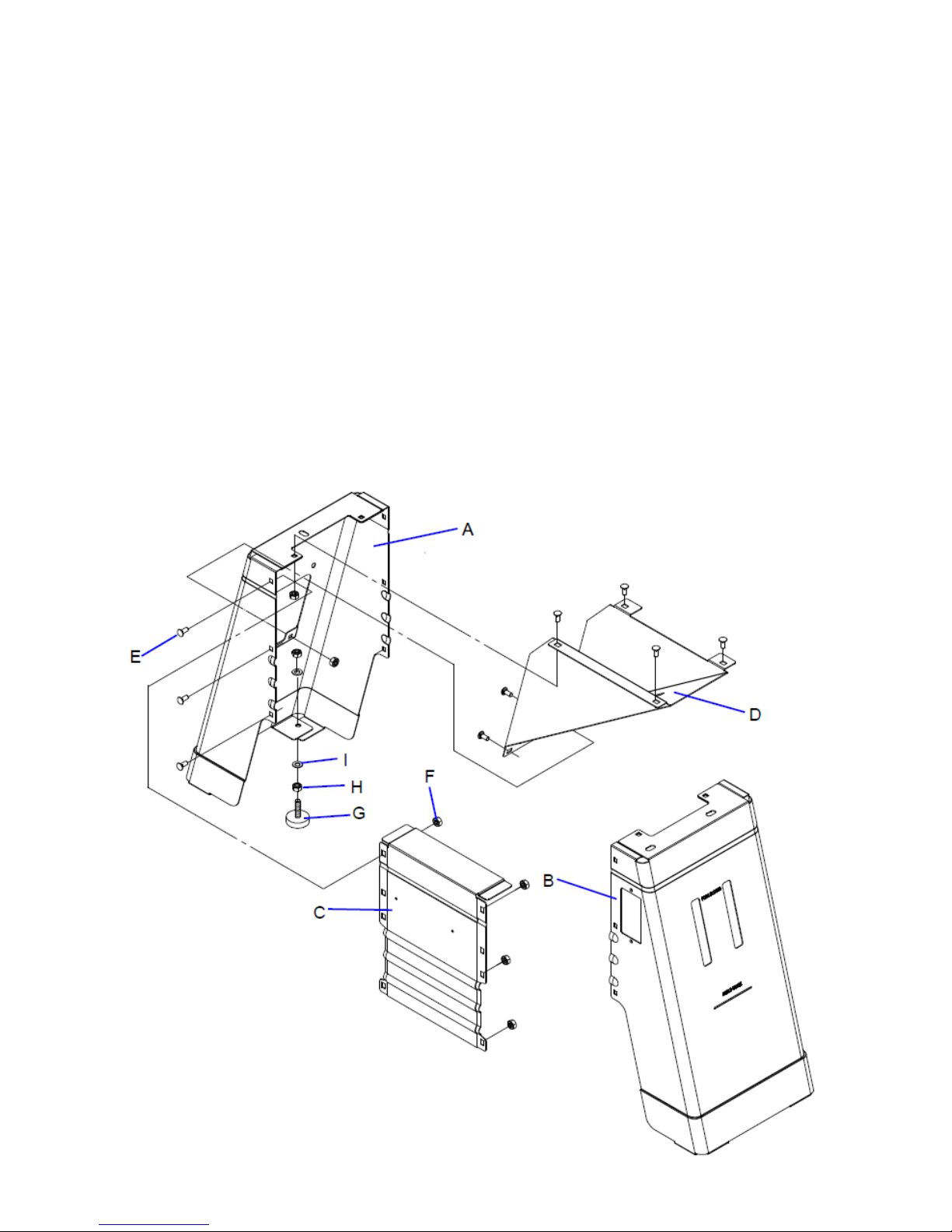
Prepare following parts for stand install
A: Stand- Left ................................ 1
B: Stand- Right .............................. 1
C: Front Panel ............................... 1
D: Motor Bracket ........................... 1
E: Shoulder Screw 5/16”x1/2” ........ 12
F: Hex. Nut 5/16”-18NC ................. 12
H: Foot Leveling ............................ 4
I; Hex. Nut 3/8”-16NC ................... 8
J: Flat Washer 10.5x27x2t ............. 8
K: Hex. Screw w/washer ............... 3
Step 1: Assembly Stand- Left (A) . Stand- Right (B) &
Front Pane (C) with Shoulder Screw (F)*6 & G Hex.
Nut*6 but not tighten all screws.
Step 2: Put Motor bracket (E) on the stand (step 1)
lock by Shoulder Screw (F)*6 & Hex. Nut (G)*6 but
not tighten all screws.
Step 3: Turn over the stand assembly upside down
then locate Foot (H) . Hex (I). Nut & Flat Washer (J)
on four corners.
4
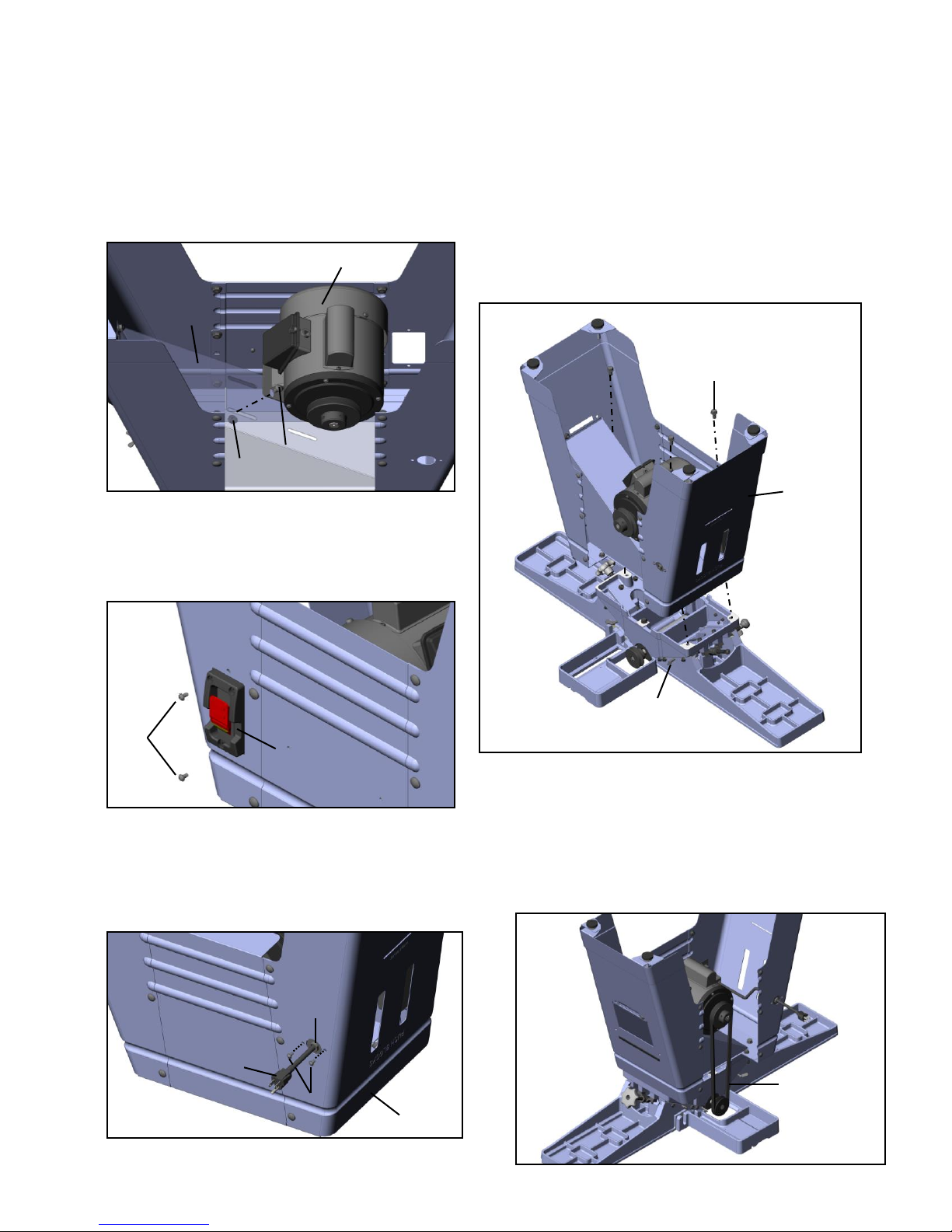
Installation Motor & Switch
Stand-Right
Switch
L
Stand-Right
M
O
N
Motor
E
F
D
Jointer Body
Stand
V-Belt
Step 4: Put the motor & switch assembly on the
Motor Bracket (D) and lock by Shoulder Screw
(E)*4 & Hex. Nut (F)*4 but not tighten all screws.
Warning: The motor & switch assembly is
heavy. Do not assemble motor by yourself; ask
someone to help is required.
Step 5: Place to switch into the rectangle hole
on stand-right and tighten by 2 Round Head
phillips screw w/teeth washer (L)
Step 6: The plug (M) need to pass through the
round hole on the stand-right and fix the power
Fixing plate (O) by Round Head phillips screw
w/flat washer (N)* 2
Installation Jointer Body & Stand
Step 7: Put a large clean carton board or plastic paper
on the floor to protect the jointer table top surface.
Step 8: Turn over the jointer Body then put the stand
of step 6 to the jointer base by 3 Hex. Screw
w/washer 3/8” x16NCx3/4” (P) but not tighten all
screws
Warning: The jointer body & stand are heavy.
Be careful and asking help when needed.
Installation V-Belt
Step 9: To attach the V-belt over cutterhead pulley
and motor pulley.
5
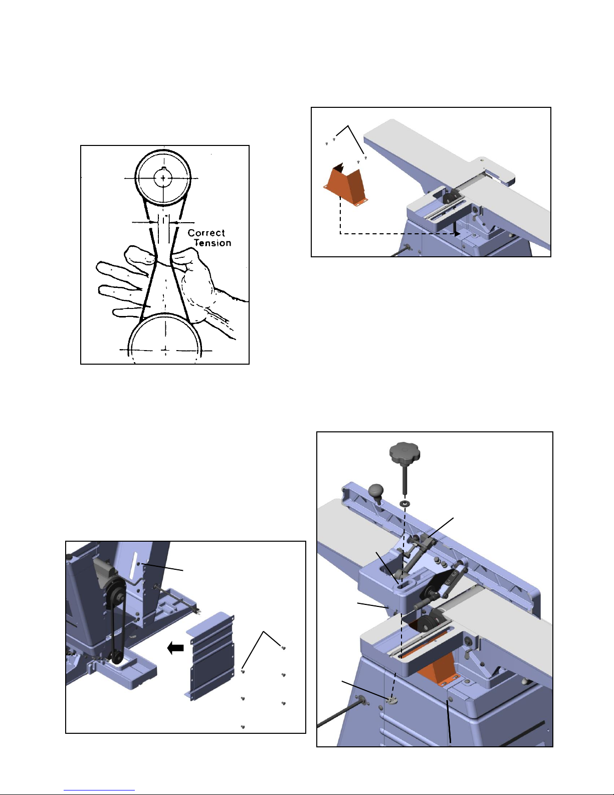
Checking Belt Tension
R
S
U
T
Fence Assembly
W
V L E
F
Step 10: Pull down on the motor to achieve the
desired belt tension (the correct belt tension is
achieved when the belt can be deflected
approximately one inch at the center belt span
using light finger pressure) Snug tight the 4
Shoulder Screw (E) & Hex. Nut (F).
Installation Rear Panel
Step 11: Assembly the rear panel after the Vbelt adjustment with 3 Shoulder Screw (E) &
Hex. Nut (F) then tighten all of screws on the
stand assembly.
Then Turn over the jointer .
Warning: The jointer with stand is heavy.
Be careful and asking help is required.
6
Installation Pulley Cover
The pulley cover is mounted with 2 Round Head
phillips screw w/teeth washer (L) to the threaded
holes in the Stand.
Installation Fence
1. Take the lock Knob (R), flat washer (S), and lock
nut (T) from the hardware bag..
2. Place the Key (U) on the Fence bracket slot then
put the fence assembly onto the table (B) Be sure
the key stock (U) on the bed lines up with the
channel (V) in the fence casting.
3. Place the flat washer (S) on slot (W); insert the
lock Knob (R) through the fence casting and the
table casting.
4. Thread the lock nut (T) onto the lock Knob
(R). Make sure the tab on the nut faces up and
engages the slot in the table casting.
Installation Blade Guard & Removal
A
Y Z X
B C D
Lock Key
Switch Assembly
WARNING: Use the jointer guard for all
operations. Do not connect the plug to power
source
1. Loosen the Round Head phillips screw
(A)from guard post (Z)
2. Turn knob (Y) counterclockwise to create
tension on spring, and hold it there.
3. Insert guard post (Z) down through hole in
front of ledge.
4. Slightly turn knob (Y), if necessary, until
the guard seats itself, and the spring
engages the slot at the end of the guard
post.
5. Check the guard for proper tension. If
guard does not spring back into place
when pulled back from cutterhead, remove
guard and adjust spring tension by repeating
steps 1-3 until correct tension is achieved.
NEVER run the jointer without the guard
being in place and in perfect working order.
6. Tighten the Round Head phillips screw
(A)from guard post (Z)
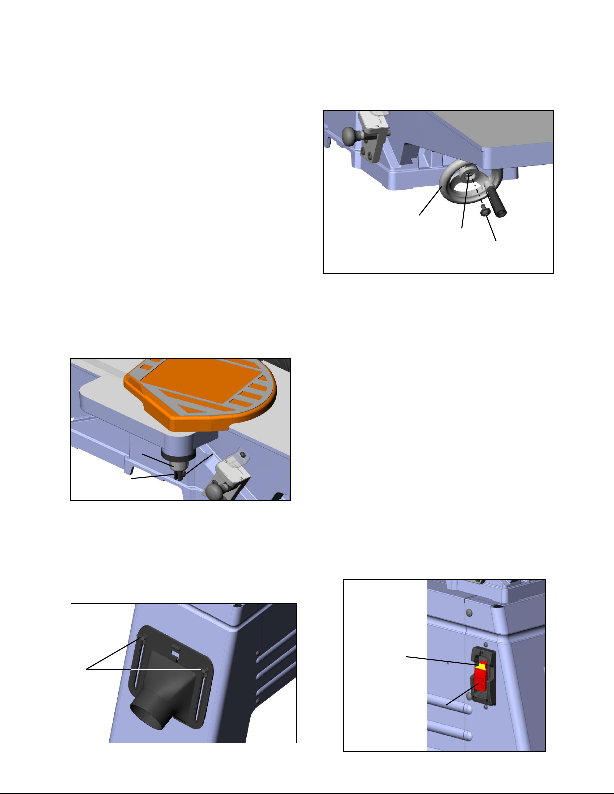
Installation Dust Chute
Mount the dust chute to the pre-tapped holes in
the side of the stand with 2 wing screws (A) .
7
Installation Handwheel
Slip the handwheel (B) onto the elevation shaft (C)
(under the infeed table) then tighten with the Round
Head phillips screw w/washers (D)
Installations are completed.
Safety Switch
This Jointer has a rocker style switch with a
removable locking key to prevent unauthorized
use. If you intend to be away from the machine for
a long period of time and there is any chance of its
use by others, especially children, Remove the
lock key with the switch in the “OFF” position.
Store it in a safe, inconspicuous place in your
workshop. To turn the planer on, insert the red
locking key and turn the switch to the ON position.
The planer will then be operable. To turn the
planer off, turn the switch to the “OFF” position.
WARNING: Always be sure the switch is in the
“OFF” position before connecting the
jointer to the power source.
 Loading...