

Olimpia splendid ClimaPiù 8 HE HP, ClimaPiù 12 HE HP, ClimaPiù 15 HE HP Instruction Manual
MANUALE D'INSTALLAZIONE
MANUALE D'USO
MANUAL FOR INSTALLATION
INSTRUCTIONS FOR USE

37
Manual for Installation

38
INSTALLATION
1 Premise 39
2 Tecnical details 40
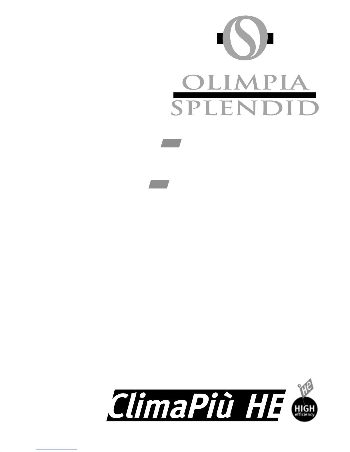
2.1 Overall dimensions 41
2.1.1 Internal units 41
2.1.2 External units 41
2.2 List of supplied accessories 42
3 Installation mode 42
3.1 Location selection of internal unit 42
3.2 Internal unit assembly 43
3.2.1 Fixing plate 43
3.2.2 Internal unit assembly 44
3.3 Location selection of external unit 46
3.4 External unit assembly 48
3.5 Laying and connection of cooling lines 49
3.6 Laying and connection of condensate
removal lines 51
3.6.1 For models 12 - 15 51
3.6.2 For Models 8 52
3.7 Laying and connection of electric lines 52
3.7.1 Power supply link up 53
3.7.2 Connecting the connection cable 53
4 Starting the appliance and topping
up the charge 54
5 Running tests and identifying
any malfunctions 55
6 Periodic Maintenance 57
7 Conclusion 57
USE
1 Presentation 59
2 Precautions 59
2.1 Nomenclature of parts 60
3 Display console 60
3.1 Air deflector 60
4 Use of appliance by remote control 61
4.1 Appliance activation/disactivation 62
4.2 Well-being function (Automatic) 62
4.3 Cooling function 62
4.4 Dehumidification function only 63
4.5 Fan function only 63
4.6 Heating function 63
(heat pump models only)
4.7 Direction positioning of air emission 64
4.8 Selection of fan speed 64
4.9 External air inlet 65
4.10 Well-being function (Night) 65
4.11 Setting of operating programmes 66
4.12 Activation and disactivation of operating
programmes 67
4.13 Resetting of all remote control functions 67
4.14 Use of appliance without remote control 67
5 Maintenance 68
5.1 Cleaning of internal unit filter 68
5.2 Cleaning of external unit battery 69
5.3 Cleaning of Bodywork 69
6 Malfunction diagnosis 70
6.1 Functional aspects not to be interpreted
as malfunctions 70
6.2 How to identify and deal with the causes
of malfunctions 70

39
1 Premise
The installation and maintenance of air-conditioning devices
such as this one could prove dangerous due to the presence
of cooling gas and live electrical parts within the appliance.
It would therefore be wise to leave the installation, initial
start-up and maintenance exclusively to trained and qualified
fitters, naturally after having read and understood this
handbook. When in doubt contact the service assistance.
Maintenance such as cleaning and filter substitution may,
however, be carried out by the user in that such tasks are
neither particularly difficult nor dangerous.
During installation and maintenance all precautions specified
in this handbook and on the labels inside each appliance
must be observed as should normal common sense and
also the security standards in force on the installation site.
Furthermore, it is always neccessary to wear gloves and
security glasses when in contact with the cooling part of this
appliance.
Pay attention to avoid burns during welding.
IMPORTANT: Before making any electrical connections
and before carrying out maintenance jobs it is essential to
open the general disconnector in order to avoid electric
shocks.
For repairs only original spare parts available from you
supplier must be used.
These fixtures may not be installed in the presence of
explosive or flammable gases.

40
2 Tecnical details
This part of the handbook contains all details necessary for a correct installation.
Model
Cooling capacity in cooling mode (1)
Heating capacity in heat pump mode (1)
Power input in cooling mode (1)
Power input in heating mode (1)
Rated input (1)
Dehumidification capacity
Power supply
Maximum power input (2)
Maximum input (2)
Protection index (outdoor unit)
Max. working pressure
COP
E.E.R
Indoor unit Air delivery in cooling mode (max-mid-min.)
Air delivery in heating mode (max-mid-min.)
Dimensions (L x H x D)
Noise level
Weight
Outdoor unit Dimensions (L x H x D)
Air delivery (max.)
Noise level
Weight
Ø connection lines (fluid)
Ø connection lines (gas)
Total limit
Vertical limit
Additional charge (over 8 m)
Refrigerant gas/charge
Power supply cable
Connection cable
Maximum remote control range
Working temperatures in cooling mode (In
÷Out)
Working temperatures in heating mode (In
÷Out)
Energy efficiency class in cooling mode
Energy efficiency class in heating mode
(1) Test conditions to verify yield (EN 814)
(2) High load test conditions (EN 814)
ClimaPiù 8 HE HP ClimaPiù 12 HE HP ClimaPiù 15 HE HP
KW 2,20 3,38 4,05
KW 2,31 3,54 4,25
W 670 1.120 1.440
W 660 1.098 1.411
A (cold-hot) 3,0/2,9 5,2/5,2 6,5/6,7
l/h 1,0 1,5 1,9
V-Hz 230-50 230-50 230-50
kW (cold-hot) 780-810 1360/1400 1710/1750
A (cold-hot) 3,5/3,6 6,0/6,2 7,6/7,8
IP24 IP24 IP24
MPa 4,0 4,1 4,2
3,50 3,22 3,01
3,28 3,02 2,81
m3/h 440 - 380 - 320 480 - 410 - 330 510 - 420 - 340
m3/h 440 - 380 - 320 480 - 410 - 330 510 - 420 - 340
mm 880 x 350 x 165 880 x 350 x 165 880 x 350 x 165
db(A) min-max 33 - 42 34-44 35-47
Kg 10 10 10
mm 810 x 530 x 220 810 x 530 x 220 810 x 530 x 220
m3/h 1700 1700 1700
db(A) max 54 54 54
Kg 34 36 38
inches - mm 1/4"-6,35 1/4"-6,35 1/4"-6,35
inches - mm 3/8"-9,52 1/2"-12,7 1/2"-12,7
m151515
m555
g/m 20 20 20
Type/kg R410A/0,950 R410A/0,91 R410A/0,90
Sect. N° of Poles 2,5-3 2,5-3 2,5-3
Sect. N° of Poles 2,5-4 2,5-4 2,5-4
m888
°C min/max (b.s.) 18/32 ÷ 15/43 18/32 ÷ 15/43 18/32 ÷ 15/43
°C min/max (b.s.) 12/25 ÷ -8/15 12/25 ÷ -8/15 12/25 ÷ -8/15
ABC
BCD
Indoor Unit Outdoor Unit
Cooling Heating Cooling Heating
DB 27°C - WB 19°C DB 20°C - WB 15°C DB 35°C - WB 24°C DB 7°C - WB 6°C
DB 32
°C - WB 24°C DB 27°C DB 43°C - WB 32°C DB 24°C - WB 18°C
41
2.1.1 Internal units
for cooling only and with
heat pump for systems
from the Split series.
2.1.2 External units
for cooling only and with
heat pump for systems
from the Split series.
MAIN ON/OFF SWITCH
2.1 Overall dimensions

42
3 Installation mode
In order to insure that the appliance is installed correctly, it
is essential to follow all the guidelines specified in this part
of the handbook. If these instructions are not followed the
applianceis correct function cannot be garanteed. In such a
case malfunction cannot be attributed to product quality and
hence the manufactureris garantee is rendered void.
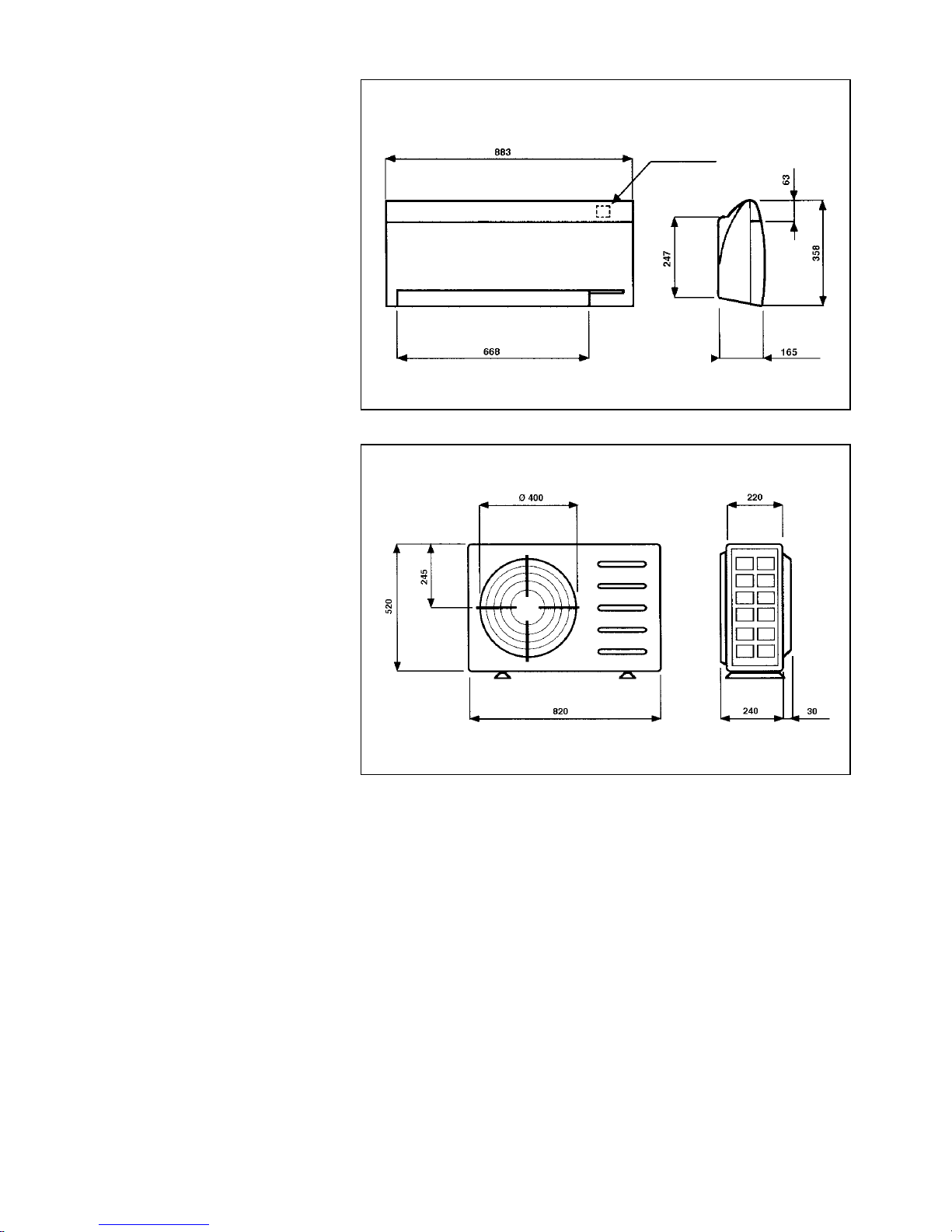
3.1 Location selection of internal unit
The internal unitis location must be selected so that:
- The bottom of the appliance is neither less than 2 m nor
more than 3 m from the ground.
- The wall onto which the appliance is to be fixed is strong
enough to support such a weight.
- Enough space is left around the appliance in order to allow
the air to circulate freely and to permit maintenance of the
appliance as specified in the overall dimensions.
- Neither air-intake nor air-outlet is obstructed; the presence
of walls or barriers with in 2 m from the outlet of the
appliance, could result in air bypasses and a consequent
reduction in the applianceis output (fig. 1 - fig. 1 bis).
- Condensate drainage is facilitated.
- The emission of air does not hit people directly, especially
those within 1,5 m from the appliance.
- The appliance is not in the vicinity of radios, HI-FI systems,
television sets, etc.
- The remote controlsis signals may be received be the
appliance.
2.2 List of supplied accessories
The consignment consists of all parts specified in the following table. It would be wise to check that all the articles are near
at hand before proceeding with assemblage.
Name Q.ty Outline Packed together with
Int. unit ext. unit
External unit 1 X
Internal unit 1* X
Remote control with infrared rays 1 X
Alkaline batteries for remote control 2 X
Support for wall mounting of remote control 1 X
Internal unit fixing plate 1 X
Screws and blocks for fixing plate to wall 1 set X
Useris Instructions Handbook 1 X
Nuts for cooling connections
(for Multisplit mod. only) 1 set X
Fixing template for the wall plate 1 X
Air Deflector 1 X
Fig. 1
43
3.2 Internal unit assembly
IMPORTANT: The cooling and condensate pipes may be
connected only in the positions indicated in the overall
dimensions.
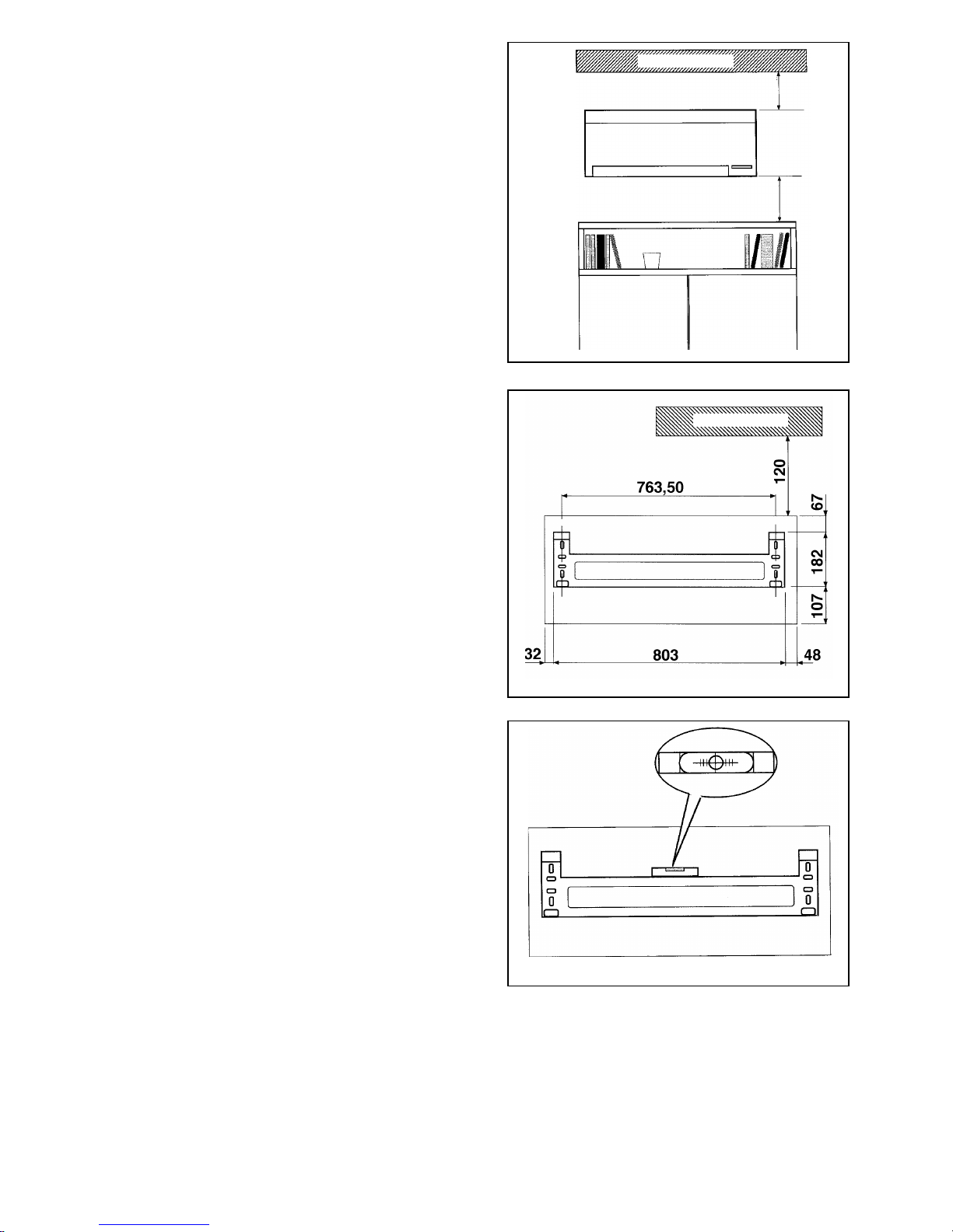
3.2.1 Fixing plate
The fixing plate onto which the internal unit is to be hooked
must be positioned keeping in mind the applianceis
dimensions indicated. Assemblage should be carried out as
follows:
a) The plate is fixed to the wall in the selected location by
means of the four blocks and screws supplied. Other
types of screws and blocks may also be used (Ø 8 mm),
as long as they have a raised head. If the wall onto which
the plate is to be fixed is made of wood then the plate
must be attached with wooden screws with a raised
head and a 5,5 mm diameter.
b) Tighten the screws slightly.
c) Use a water level to level the plate (fig. 3).
d) Tighten the srews completely.
e) Check the plateis stability by pulling it downwards and to
the side.
120 mm
350 mm
Fig. 1 bis
CEILING
Fig. 2
Fig. 3
CEILING

44
3.2.2 Internal unit assembly
Once the plate has been fixed, assemble the internal unit
using the following preocedure:
a) If the connection lines are at the back of the appliance,
a 100 mm hole must be drilled in the wall with an outward
5% gradient (fig. 4) in order to facilitate condensate
removal. The position of the hole is indicated in fig. 2.
The best procedure is to make a preliminary hole in the
wall with a 8-10 mm nail in correspondence with the
centre of the hole to be drilled and then bore the
definitive hole using a drill with a guided cup. If there is
an "external air intake" included in the appliance, then a
hole must be drilled for this also, in the position indicated
in the instructions supplied with the accessory and
assemble it in accordance with these instructions.
b) Insert the condensate removal line, cooling line and the
wires for electrical connection or the raceway in which
they are contained into the hole.
c) Remove the applianceis front panel in the following
manner (fig. 5):
- remove the three screws from the air outlet and the
other two from under the upper door,
- grip the frontal panel from below, turn it upwards to
free it from the lower part,
- lift the panel in such a way as to unhook it from the
two hooks under the upper door.
d) Bend the lines to the right (fig. 6) in the direction of the
connections. Use a tube bending spring to avoid
"pinching" the lines.
ESTERNO
INTERNO
Fig. 4
Fig. 5
Fig. 6
CEILING
INSIDE
OUTSIDE
5% SLOPE

45
e) Hook the appliance to the upper part of the plate (fig. 7)
in such a way that the lower part may be lifted.
f) Pass the external unit connecting wires inbetween the
motor and the electronic card casing and connect them
up to the connecting terninal board (fig. 8) in accordance
with the modes indicated in the electric circuit
arrangement (see paragraph 3.7).
g) Place a stopper between the appliance and the wall (fig.
9) to create sufficient space for the cooling and condensate connections to be carried out according to the
modes specified in paragraph 3.5 and 3.6.
Fig. 7
Fig. 9
Fig. 8
SOLUTION WITH POWER
SUPPLY FROM THE OUTSIDE
SOLUTION WITH POWER
SUPPLY FROM THE INSIDE

46
h) Remove the stopper, lift the device slightly and lower it
in order to connect it to the plateis lower hooks resulting
in a perfectly sturdy fixture (fig. 10).
i) Pull the appliance downwards and to the side to check
that it has been hooked up properly to the plate.
j) Connect to the mains as indicated in paragraph 3.7.
k) Close the front panel once more, tighten the screws
inside the air outlet and the two screws within the upper
door.
l) Check once again that the unit is perfectly level or,
at most, that it slants 2 mm towards the side where
condensation is drained.
3.3 Location selection of external unit
The external unitis location must be selected so that:
- The appliance is protected from direct sunlight.
- The base is strong enough to hold the weight of the
appliance; if, in order to carry out maintenence jobs, it is
necessary to stand on the base, then the said base will
have to be strong enough to hold both the person and the
appliance.
- The appliance remains above the base at a distance
equal to that of the maximum foreseeable snowfall.
- The appliance never remains exposed to heavy downpours
(as can happen when a drain pipe gets clogged up and the
gutter overflows).
- Sufficient space is left around the appliance to inable air
circulation and maintenance as specified in the overall
dimensions.
- Pathways are not obstructed.
- The appliance can be securely fixed to the base.
- Neither fumes nor noise emissions can disturb the
neighbourhood in any way. As regards noise levels, the
Hygiene Regulations in force on the site must always be
respected. If noise levels are too high, soundproofing
should be installed without obstructing neither aircirculation nor maintenance.
- The appliance is facing prevalent winds according to fig.
11.
- The appliance is not in a leeward position as regards burnt
gas smoke stacks and does not undergo contact with
vapours and oily or corrisive gas emissions.
- The condensate can be easily removed (in the case of
heat pump appliances).
- The internal unit connecting lines (or internal units in the
case of the Multisplit series) are not longer than 15 m in
each direction (when more than 10 m, the charge must be
topped up with 25 g of R410A for each extra meter).
Furthermore, the maximum difference in height between
the external and internal unit (or in the case of Multisplit,
the internal units) is not more than 5 meters.
The external unit must be perfectly horizontal and therefore
before going ahead with its positioning it is essential to
ensure that the support surface is perfectly level.
If the appliance has to be installed in an overhanging
position on the wall it is advisable to use an "Assembly
Fig. 10
Fig. 11
AIR
VENTING
AIR
INTAKE

47
bracket for the external unitis wall-mounting" which is
available on request. As regards the assembly follow the
instructions enclosed in each respective box.
We would also like to indicate some precautions to be taken
during assembly:
In areas susceptible to snowfalls
By means of support walls or a base of metal sections the
appliance must be lifted above ground level at a distance
greater than the height of a maximum foreseeable snowfall
because:
- if the appliance does not work by heat pump, during the
thaw, the water could get into the system causing damage
to the electrical devices,
- if the appliance works by heat pump, the drifting snow
could obstruct the regular air circulation and make condensate drainage difficult.
Appliance assembly on ground level, roof, terrace, etc.
in not easily accessible locations
The base must be lifted to avoid stagnant rain water and dirt
accumulation underneath the appliance. It is therefore
advisable to raise the appliance approximately 15 cm off the
ground by means of two small walls onto which the appliance
is fixed with two anchor bolts. The above is not necessary,
however, if the appliance is to be installed on a balcony as
balconies already slope to aid rainwater drainage and are
usually found in fairly protected locations hence there should
be no danger of dirt accumulation under the appliance.
On a rigid metal base (Brackets, metal support sections,
etc.)
In this case the appliance must always be fixed to the base
by means of elastic vibration-damping blocks (not supplied
with the appliance) underneath the four support points
which are selected in relation to the applianceis weight.
Furthermore, the base must be rigid enough to avoid
amplifying the vibrations caused when the appliance is
running.
Heat pump appliances
When the heating is on, a condensate or water is produced
in the external unit due to defrosting. Such water must be
eliminated to avoid stagnation. In particular, when the
appliance is assembled directly on the ground a drainage
channel should be made around the base of the appliance
which depends on the drainage system running from the
building. If the appliance is installed on a balcony it is
possible to position it over a tray in galvanized sheet iron or
better still in stainless steel (not included with the appliance)
which remains above ground level and which is equipped
with a drainpipe from which the condensate can be made to
flow using the most opportune method (for example, into a
gutter).
Furthermore, even if the appliance is resistant in inclement
weather, it should be assembled in a location which remains
protected or it should be covered with its own roof which
permits the air to circulate freely through the appliance.
 Loading...