

Page 1

CNC 501
Programming and Operation of Lathes
York Technical College
452 South Anderson Road
Rock Hill, SC 29730
Page 2

Page 3

TABLE OF CONTENTS
I. General Safety and Standard Operating Procedures
II. OSP Control Functions
• Primary and Secondary Modes
• Parameters; Soft Limits vs. Stroke End Limits
• Function of all keys on Machine Operation Panel
III. Manual Machine Control
• Door Interlock restrictions
IV. Coordinate System and Program Zero Point
• Coordinate System
• Absolute Position Encoder Advantages
V. Program Codes
• G Codes
• Additional G Codes
• M Codes
VI. Program Format and Data Word/Address
• Refer to LB25-T min Program at Front
• Begin with Simple Examples; T-Command will be covered in detail later
• Discuss comments inside Parentheses
• Tool Offset relationship to zero set
VII. Angle Command
VIII. Circular Interpolation
• Write Simplie Program on Board Part DR202-3
1. Eliminate speed and gear range
2. Write program with zero at front and back
• Write Program on Board for DR201-3
1. Have a student key in the program on simulator as you write
2. Add graphics commands to program, without explanation to students
• Call Up and Test Program
• Review
IX. Machining Guidelines
• Surface Footage, Feed rate and Depth of Cut
• Cutter Radius Compensation
1. What CRC is; how it works; and it’s advantages
2. CRC Cancellation
Page 4

X. Auto Chamfer and Automatic Radius
Xl. LAP Cycles
• LAP Cycle Concept
• Types of LAP Cycles
• Write new program for DR201-3 and modify to use LAP cycles
Xll. Miscellaneous Cycles
• Drilling Cycles
• Grooving Cycles
• Tapping Cycles
XIII. Threading Fixed Cycles
XIV. Subprograms, Schedule Programs, and Additional File Types
• Schedule Program – Explanation
• Common Variables
• Local Variables; use variable jaw-boring program as an example
XV. Graphic Commands
XVI. Appendix
Page 5

Programming and Operation
of 2 Axis Lathe
Course Objectives - Upon completion, the individual will be procient in all basic skills necessary to
allow the functional/productive operation of the machine tool and associated safety practices.
The course is designed to provide the knowledge and skills required to “translate” the part drawing
into a nished product. The individual will be capable of dening the list of required processes, their
logical/optimum sequence, create the complete CNC part program, install the appropriate tools correctly, establish the program zero point, and perform corresponding tool offsets.
Course emphasis is a blend of classroom instruction, time spent on the machine tool, and individually
displayed skills.
Mastery of the topics is measured by actual demonstration and examples.
Page 6

Page 7

GENERAL SAFETY
AND
STANDARD OPERATING
PROCEDURES
Page 8

General Safety and Standard Operating Procedures
SAFETY PRECAUTIONS/STANDARD OPERATING PROCEDURES..................................
PRE-POWER UP CHECKLIST...............................................................................................
CHUCK PRECAUTIONS........................................................................................................
PRECAUTIONS FOR MACHINE OPERATION......................................................................
SETUP....................................................................................................................................
WORK PIECE LOADING AND UNLOADING.........................................................................
END-OF-DAY CHECKLIST.....................................................................................................
WHEN A PROBLEM OCCURS..............................................................................................
OTHER GENERAL PRECAUTIONS......................................................................................
Page 9

SAFETY PRECAUTIONS
Okuma machines are fully equipped with various safety devices to prevent operators and the
machine itself from accidents. However, operators are urged to operate the machine with safety in
mind. Strict observance of all safety guidelines indicated in the documentation provided with the machine is essential. The following are some points to observe when working with any machine tool.
PRE-POWER UP CHECKS
1) Close the doors of the electric control cabinet and the operation panel.
2) Never place obstacles around the machine.
3) Turn on power to the machine in the following sequence:
a) Depress the Emergency stop button
b) Turn on the Main power disconnect.
c) CONTROL ON button on the operation panel. (POWER ON button on the control
cabinet on machining centers.)
4) Once the control ‘boots up’, release E-stop and press the Control On button.
CHUCK PRECAUTIONS
1) Before starting the spindle or cutting operations, close the front door.
2) Strictly observe the allowable spindle speed for the chuck installed. Never exceed the maxi
mum allow able spindle speed.
3) When a chuck or xture unique to the user’s applications is used, check the allowable maxi
mum spindle speed and run the spindle within the allowable range. Pay due attention to work
piece gripping force and balance.
4) The maximum spindle speed can be limited by inputting the spindle speed with G50. To
ensure safety in operation, input this spindle speed limiting command in the program
(G50S****).
5) If the spindle is operated at a speed close to the allowable maximum speed:
Avoid imbalance in the work piece clamped in the chuck. Apply the maximum allowable
pressure to grip the work piece since increased centrifugal force reduces the chuck’s gripping
force.
Page 10

The maximum allowable spindle speed and applicable pressure for the chuck are indicated on
the name plate attached to the front door as well as on the chuck body. The maximum allow
able speed and the applicable pressure ensure a chucking force larger than one-third the
original chuck gripping force with the standard soft-to[ jaw set in line with chuck body’s outer
periphery.
6) When special jaw larger than standard soft-top jaws are used:
Lower the spindle speed because the chuck’s gripping force is reduced due to increased
centrifugal force and lowered efciency.
If the jaw-clamping nut (jaw nut) is outside the chuck’s outer periphery, only one clamping bolt
holds the jaws in place, causing very dangerous conditions. Jaw nuts must always be located
within the chuck body’s outer periphery
Machine the jaws to the shape of the work piece.
7) Tighten the bolts on the chuck body, jaws, and block securely. Clamping force should be
greater than 40 to 50 kg.
DAILY CHECKS
1) Before starting daily operations, always check the lubrication oil levels.
2) Always use the specied brand or grade of lubrication oil.
3) For cutting uid (coolant), use Okuma’s recommendation whenever possible.
4) Change and replenish lubrication oil for each reservoir at the predetermined schedule as
explained in the operation & maintenance manual.
5) Clean the lters periodically according to the schedule explained in the operation &
maintenance manual.
6) Check the pressure gauges of the air and hydraulic lines to make sure they all read the correct
values as specied in the operation & maintenance manual.
7) For any work required inside the machine door, turn off power and ensure safety before hand.
For work done at the back of the machine that requires the operator to enter the machine operating zone, do not forget to turn off power before attempting any work.
PRECAUTIONS FOR MACHINE OPERATION
1) Always follow the instructions given in the operation manuals.
2) Never run the machine without protective covers and doors, such as the front door and chuck
cover.
Page 11

3) Close the front door rst before starting the machine.
4) With a new program, never attempt to start actual cutting operations. First run the program
without setting a work piece in the machine to check machine operations and interference;
after making sure that the program is completely free of bugs, cut a work piece in the single
block mode operation. Only after making sure that the work piece can be cut without problems
in the single block mode operation should the automatic mode operation be started.
5) Before attempting the following, always make sure that untended operation can be
accomplished safely:
Spindle rotation
Turret indexing
Axes movements
6) While the spindle is revolving, never touch chips or the work piece.
7) Never try to stop a revolving object with hands or tools.
8) Conrm the jaw installation conditions, hydraulic pressure, and allowable maximum speed for
the power chuck.
9) Check the installed conditions and arrangement of the tools.
10) Conrm the tool and zero offset settings.
11) Set the spindle speed and feed rate override dials to 10%.
12) Before feeding the turret, conrm the soft-limit settings and the emergency limit switch settings
for both X and Z-axes.
13) Conrm the position where the turret index or rotation is allowed.
14) Conrm the tail stock position.
15) Make sure that cutting is conducted within the allowable transmission power and torque
ranges.
16) Clamp the work piece in the chuck or xture securely.
17) Check the cutting uid nozzle positions. Set them at positions to supply cutting uid correctly
to the cutting point.
SETUP
1) Always make sure that the setup is complete
2) After changing the setup, operate the machine step by step to make sure the cutting can be
conducted without problems.
Page 12

3) Before replacing the chuck and/or chuck jaws, make sure that the new set is for the job
intended.
4) When two or more workers work as a group, establish the necessary safety signs, for example,
when lifting or setting heavy objects conrm with other workers whether or not it’s ‘okay’ to
start the next process.
5) When handling heavy objects, use a crane or equivalent tool.
6) When attempting unfamiliar setups, check the setup again before going on to the next step.
WORK PIECE LOADING AND UNLOADING
1) Load and unload work pieces securely.
2) Retract the turret before loading and unloading a work piece to a position where the cutting
tools on the turret will not injure the operator’s hands.
3) Before attempting to load or unload a work piece, make sure the spindle has come to a
complete stop.
4) Before running a new program, rst rotate only the spindle to make sure the work piece is
securely clamped in the chuck.
5) To machine irregularly shaped work pieces, make sure the work piece is clamped in the chuck
securely without imbalance.
6) When handling heavy work pieces, use a crane, hoist, or other tool.
7) Before setting a work piece in the machine, make sure the work piece has portions that can he
used for proper chucking.
AT THE END OF THE DAY
1) Clean the machine.
2) Locate the turret at the predetermined retraction position.
3) Before leaving the machine, turn off all power switches.
4) Turn off power to the machine in the following sequence:
CONTROL OFF button on the operation panel. The main power disconnects.
Page 13

WHEN A PROBLEM OCCURS
1) Stop all spindle(s) and axis movement by pushing the closest EMERGENCY STOP switch.
2) Contact the maintenance person to determine what action to take.
3) Use only the fuses and other replacement parts of the specied rating.
4) Be extra careful when handling the following high-voltage units:
Main Breaker
Servo Drive unit (BL-11D)
VAC drive unit
Power cables
OTHER GENERAL PRECAUTIONS
1) Wear suitable safety clothes.
2) Keep work areas clean as well as the machine.
3) Do not touch controls with wet hands.
Page 14

Page 15

OSP CONTROL FUNCTIONS
Primary/Secondary Modes
Parameters - Limits
Function of all keys on Machine Operation Panel
Page 16

Turning the Power ON and OFF
Turning the Power ON
< Procedure >
(1) Turn ON the main switch at the control box.
(2) Press the [CONTROL ON] button on the NC operation panel.
(3) The NC control software is loaded from the data storage memory to the operation
memory and the NC starts running. File names are displayed on the screen, as they are
loaded to the operation memory.
(4) SBP 6-A V*.**-*(???)
MEMORY TEST :0000
BOOTDEV FROA:
LOAD:SYS
OPERATING SYSTEM PROGRAM V*.**-*(???)
OKUMA 1997.**.**
File names of NC application software to be loaded
PBU FILE ON LOADING
FIRMWARE FILE ON LOADING
GRAPHIC DATA ON INITIAL PROCESSOR
Turning the Power OFF
< Procedure >
(1) Make sure that all machine operating commands are completed.
(2) If a peripheral (printer, punch, etc.) is connected to the NC, switch off the peripheral.
(3) Press the [CONTROL OFF] button on the NC operation panel.
(4) Turn OFF the main switch at the control box.
Notice: NC control data and mode information are backed up to the data
storage memory at preset intervals. Therefore, the data may not be
backed up if the power is turned OFF immediately after changing the
data. Back up the data, press the function key (BACK UP) before
turning the power off.
Page 17

Emergency Stop
(1) Emergency Stop
Press the [EMERGENCY STOP] button to stop the machine in an emergency. The
machine stops immediately if the [EMERGENCY STOP] button is pressed.
(2) Recovery from the Emergency Stop State
The [EMERGENCY STOP] button is a push-to-lock type switch and it is locked in the
pressed state. To unlock the button, turn the button in the direction indicated by an
arrow on the button.
After unlocking the [EMERGENCY STOP] button, press the [CONTROL ON] button on
the NC operation panel, so that the NC can recover from the emergency stop state.
Page 18
Turret Home Position - this refers to the position to which the turret must move to
before the turret can index a commanded tool into the cutting position. The
turret home position is also called the turret index position.
For the turret to be able to index, it must be positioned on either the
positive X, or Z axis limits .
Whenever the turret slide is at a ‘limit’, the OSP panel light illuminates,
indicating a valid position to index the turret.
For obvious reasons, the position for turret indexing should always allow
for the longest tool in the turret to safely clear the chuck, etc. . Given the
rapid axis speeds moving an additional 3 or 4 inches from the work piece will improve
overall safety and cause little if any increase in net cycle time.
The turret indexing position can be placed anywhere within the
machine working range. To index the furthest distance from the chuck, the turret should move
to the positive stroke end limits - in X and Z.
Page 19
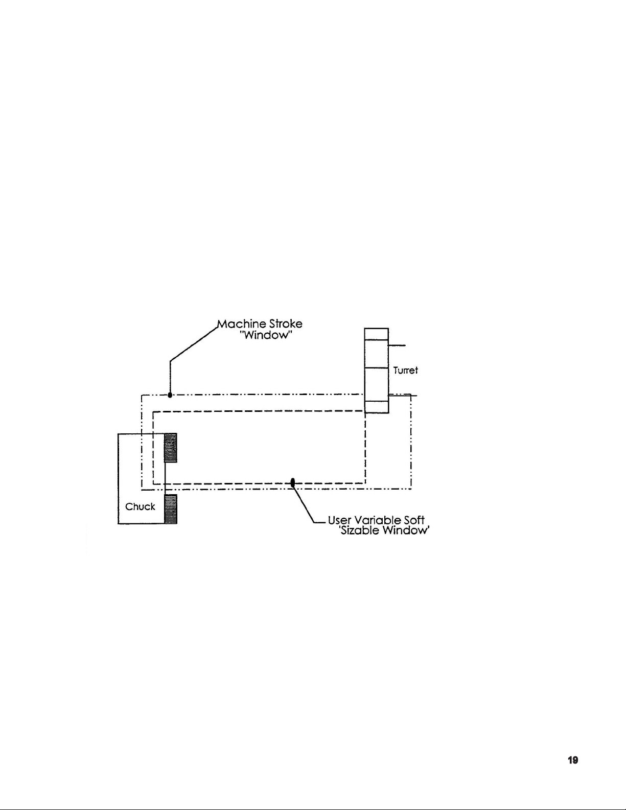
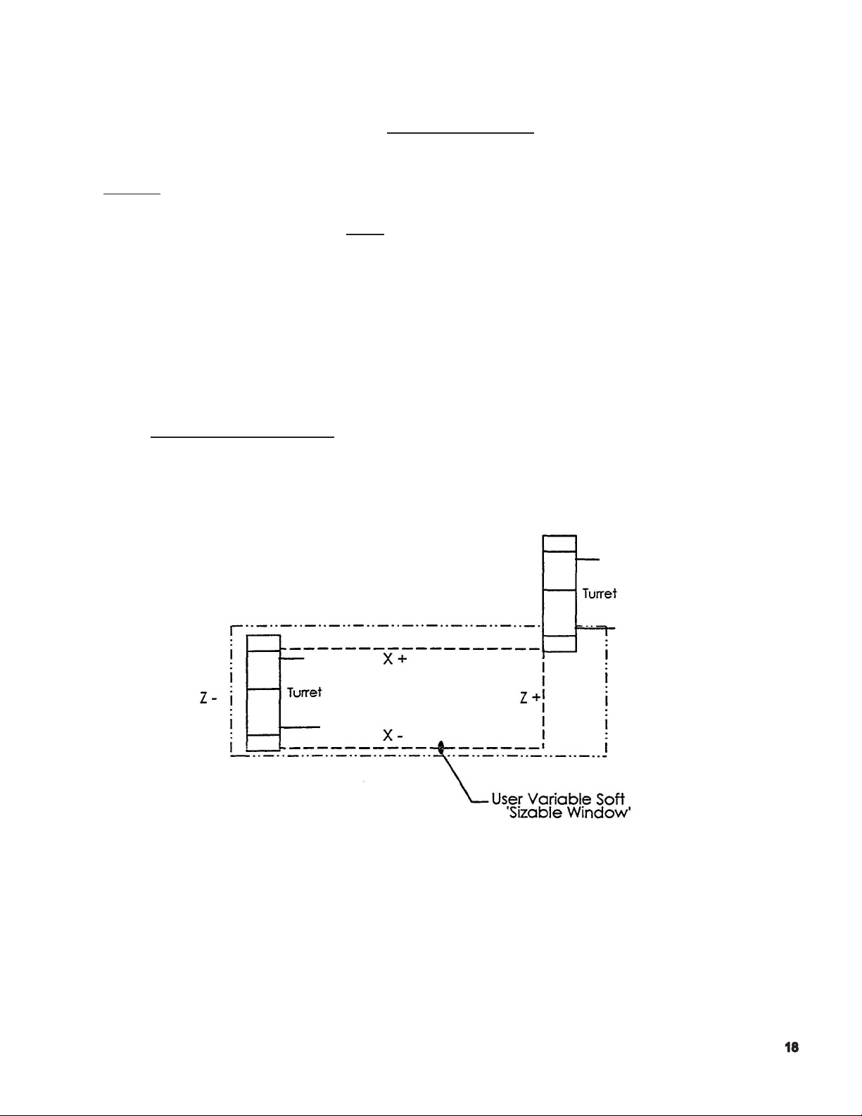
User Soft Limit / Variable Soft Limit - within the machine’s stroke end limits, it is possible to
establish/dene a smaller ‘window’ used to dene a smaller working range. The boundaries of
this smaller window are called user soft limits.
The primary reason to establish a ‘soft limit’ is to reduce the distance the turret has to travel
in order to ‘be at a limit’ and receive the conrmation signal, so that a turret index command
may be executed.
The machine’s turret will not index until either the ‘X’ positive, or ‘Z’ positive
limit condition is satised .
Page 20
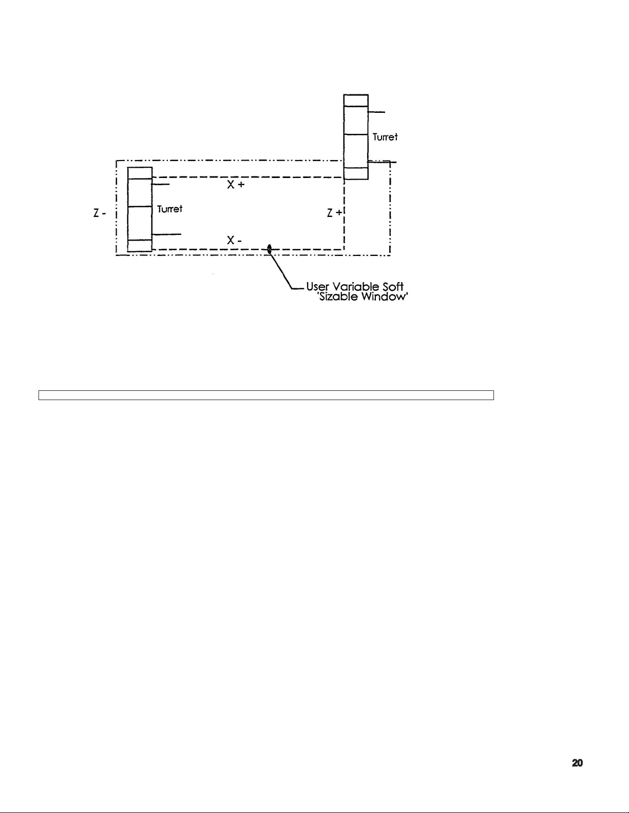
The following illustration depicts the ‘working range’ within which the turret can travel, based on those ‘soft
limits’ that have been dened in the OSP control.
Note: In the above illustration, the ‘chuck’ is not shown for reasons of clarity.
To make the turret travel to its [X+, Z+} limit, the user should use the following command:
G00 X50 Z50
This command will position the turret to the current soft limits, which may or may not
be representative of the machine’s maximum stroke end travel.
Notes:
1. Positioning the turret to the “limits” cannot be performed by using a G01
command.
2. The user must select a ‘X’ and ‘Z’ value that will always exceed the machine’s working range.
A general rule of thumb is to double the actual axis stroke amounts. Using X50, Z50 will
sufce for the majority of instances, except for those machines with considerable bed length.
Page 21

Problems
1) If your part has a program zero at the front of the part, explain why the Zs in the program have
a negative sign in front of the numbers?
2) What is meant by soft limits?
3) Where is the turret home position?
4) How do you know if the turret slide is at a slide limit?
5) What is meant by the positive stroke end limit?
6) Also, what can you do with the turret when it reaches that limit?
7) What is the line code that will allow you to index the turret?
Page 22

OPERATION
Basic Construction of Operation Panels
For operating the machine, the following four kinds of man-machine interfaces are provided:
(1) NC Operation Panel
It is used for le operation and data setting.
(2) Machine Operation Panel
These switches and keys used mainly for manual operation. They are located in the
controls operation panel.
(3) Option Panel
An option panel is provided, which contains switches and indicating lamps required for
user specied options. Arrangements of the switches and indicating lamps differ
depending on the selected optional specication.
(4) Foot Pedal (Foot Switch)
A foot pedal is provided to control chuck open/close and tail stock spindle advance/
retract.
Various types of operator panels are included, depending on the shape of
the panel and the arrangement of the controls. External views of the operator panels
are provided in the Appendix of this manual.
Page 23

Outline of Controls on Operation Panel
Operation Mode Selection Keys
(1) AUTO Key
Select the automatic mode when operating the machine using
a stored part program.
(2) MDI Key
Select the MDI mode for block operation, permitting input of the data
necessary for operation by the keyboard in the NC operation
panel.
(3) MANUAL Key
Selects the manual mode for operator by the switches on the machine
operation panel.
Data Setting Mode Selection Keys
(1) EDIT AUX. Key
Selects the program operation mode for operating program les and
data les. In this program operation mode, it is possilbe to edit input/
output, display or delete a program le.
(2) PARAMETER Key
Selects the parameter mode for setting, changing or displaying
parameter data necessary for NC control.
(3) ZERO SET Key
Selects the zero set mode for setting, changing, or checking the
zero offset data and zero shift data which dene a program coordinate system.
(4) TOOL DATA
Selects the tool data mode for setting, changing, or displaying the
tool offset data, nose R compensation data, tool shape data, and load monitor data.
(5) MacMan
Selects the MacMan (machining management function).
Page 24

NC Status Indicating lamps
(1) RUN Lamp
The RUN lamp 15 on when the machine is operation in the
automatic or MDI mode.
(2) S.T.M Lamp
The S.T.M. indicating lamp is on while auxiliary function operation
such as spindle gear range change, tool change, and spindle rotation, is executed.
When an axis movement command is designated with an S, T, and /or M command,
the axis movement command is executed after the completion of the S, T, and /or M
command designated in the same block.
If a spindle gear range command, spindle speed command, or tool number command
is changed using the manual intervention function (called out by pressing the [MID
AUTO MANUAL] key), the S.T.M. indicating lamp blinks.
(3) SLIDE HOLD Lamp
The SLIDE HOLD indicating lamp is on when the [SLIDE HOLD]
button is pressed in the automatic or MDI mode.
For the two-saddle option, it also goes on if the operation of either of
the two saddles enters the slide hold state with the other saddle having
completed single block mode operation in the automatic mode.
(4) PROGRAM STOP Lamp
The PROGRAM STOP indicating lamp is on during the execution of
a program stop (M00) or optional stop (M01) function in the automatic
or MDI mode.
The indication lamp blinks during the execution of a dwell (G04) function.
(5) LIMIT Lamp
The LIMIT indicating lamp is on when either X- or Z - axis reaches
its limit position.
For the two-saddle option, the indicating lamp is on if any of XA, ZA-,
XB-, and ZB - axis reaches the limit.
The indicating lamp blinks if the actual spindle speed reaches the maximum or
minimum speed of the selected gear range, or when it reaches the spindle speed
specied using the maximum spindle speed specication function.
Page 25

(6) ALARM Lamp
The ALARM indicating lamp is on when the machine malfunctions or
an incorrect program is input. It is also on if the computer
fails to function correctly.
Page 26

Status Indicating
Lamp
RUN - The machine is normally running in
S.T.M -The machine is waiting for the
Condition for ON Condition for Blinking
the AUTO or MDI mode
(except for during the SLIDE HOLD
and PROGRAM STOP mode).
operation completion of an M code
command. (Spindle rotation command, gear command, etc.).
- A spindle speed command is given
(S command).
- A turret rotation command is given
(T command).
Only for the multi-machinig options:
-The program selection command is a
schedule program is being executed.
-The following items have been
changed during manual intervention.
Tool number
Spindle rotation/gear command
Only for the multi-machining specication
-The machine is waiting for the
operation completion of a multi-machining M code command.
(C-axis joint command , M-tool
spindle rotation command, etc.).
-An M-tool spindle speed command
is given (SB command).
-The C-axis brake pressure is
switched between high and low.
Only for the ATC specication
- The machine is waiting for the operation completion of the MG, MT or
TN command.
SLIDE HOLD -The SLIDE HOLD button has been
pressed in the AUTO or MDI mode.
C- axis joint state
C-axis clamp
M-tool spindle ratation/gear
command
Does not blink.
-A block of program commands
has been executed on one saddle
while the other saddle is placed in
the slide hold mode with the single
block function activated in the AUTO
mode.
PROGRAM STOP -M00 OR M01 is designated in the
AUTO or MDI mode.
-The dwell command (G04) is executed.
Page 27

Status In dicating
Lamp
LIMIT -Either X- or Z -axis has reached
ALARM -Any erroneous operation is at-
Condition for ON Condition for Blinking
the variable soft-limit position.
tempted (An alarm of level A, B,
C, or D).
-The spindle speed has reached the limit in
the selected gear range.
-The spindle speed has reached the limit
specied by the maximum spindle speed
designation function.
-The spindle position is controlled after the
completion of spindle orientation (DIFF
control).
-The M-tool spindle position is controlled
after the completion of spindle orientation.
Does not blink.
Page 28
Other Controls on NC Operation Panel
(1) Function Keys: F1 to F8
There are eight function keys on the NC operation panel.
When an operator selects a desired operation mode, the screen displays the T
operation functions at the bottom line. Each function corresponds to a function key
(F1 through F8). Select the function to execute and press the corresponding function key.
If all functions called out by the selection of a mode cannot all be displayed
simultaneously, the ([EXTEND]) message is displayed for function key [F8]. In this case,
press [F8] to display the rest of functions.
[F1] [F2] [F3] [F4] [F5] [F6] [F7] [F8]
(2) ? (Help) Key
This key is used to display the description of the alarm which occurred during machine
operation and also the alarm history.
It shows actual position data, part program data, block data, zero offset values, tool
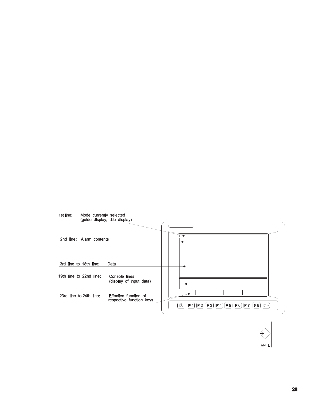
offset values, parameter data, alarm description, etc.
The basic format of display on the scree
(3) WRITE Key
n is shown below.
The [WRITE} key to select an operation and also conrms
input data.
Page 29
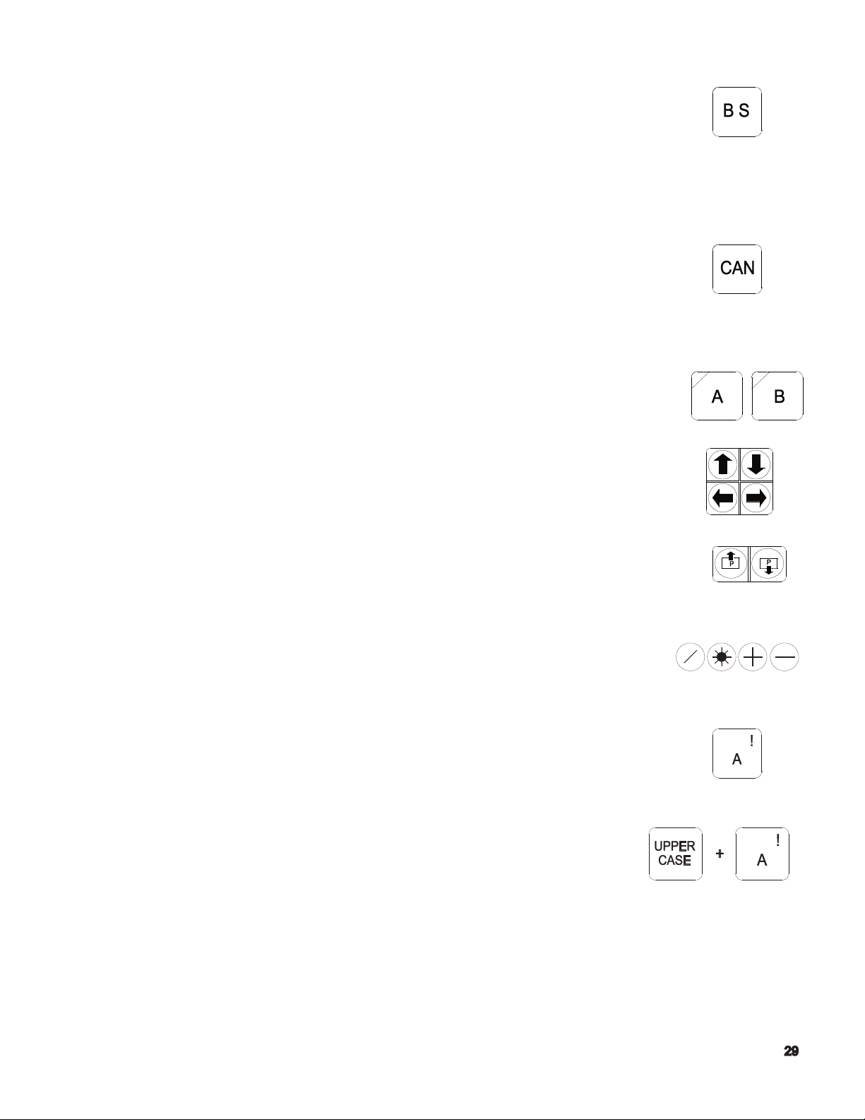
(4) BS (Backspace) Key
The [BS] key is used when erroneous data has been input.
Each time this key is pressed, the character input last is erased.
For the display of le index and list, this key is used to display the next
page.
(5) CAN Key
The [CAN] key is used when erroneous data has been input.
Each time this key is pressed, one line of the data is erased.
(6) Turret Selection (AB) Keys
These keys are used to select the appropriate turret or saddle
(A saddle side, B saddle side) for NC control of the two-saddle
or two-turret models.
(7) Cursor Keys
Four cursor keys are used to move the cursor displayed
on the screen.
(8) Page keys
If the information called out is displayed in more than one
page, the page keys are used to change the display page.
(9) Operator Keys
These keys are used when an operator edits a program or enters data.
(10) Character Keys
Character keys are used for inputting a character for data
input, program operation, and le edit operation.
(a) To input a character shown at the upper right
corner of a key top, use the [UPPER CASE] key.
Page 30

(b) When the [CAPS LOCK] key is pressed
(indicating lamp at the upper left corner lit), upper
case alphabetic letters A to Z are input. When the [CAPS LOCK]
key is not pressed, lower case alphabetic letters a to z are input.
(11) Numerical Key Pad.
These keys are used for inputting numbers for data input,
program operation, and le edit operation.
(12) Contrast Adjusting Keys
(only for Operation Panel with Monochrome STN Screen)
These keys are used to adjust the contrast for the display.
Controls on Machine Operation Panel
Flat keys used on the machine operation panel have features as indicated
below depending on whether or not they have an indicator lamp.
< Flat keys with an indicating lamp >
The indicating lamp in a key indicates if the function of the key
is valid or not.
- Indicating lamp lit . . . . . . . . . Key function is valid.
- Indicating lamp unlit . . . . . . Key function is invalid.
< Flat keys without an indicating lamp >
The function of the key is valid only while the key is
held down. If the key is not pressed, the function is invalid.
(1) CONTROL ON Switch
The [CONTROL ON] switch is used to turn on the
control power of the NC unit after turning on the main switch of the machine.
The pilot lamp in this switch lights when the control power is turned on.
If the [EMERGENCY STOP] button is pressed, the pilot lamp in this
switch goes off. To leave the emergency stop state, press the
[CONTROL ON] switch.
Page 31

(2) CONTROL OFF Switch
The [CONTROL OFF] switch is used to turn off the control
power of the NC unit.
When shutting off the power, turn off the control power rst by pressing the [CONTROL
OFF] switch before turning off the main switch of the machine.
(3) RESET Key
The NC unit is reset when the [RESET) key is pressed.
The key is used to reset an alarm.
(4) NC PANEL Switch
(a) UNLOCK position
Enables all controls on the NC and machine operation panels.
(b) EDIT LOCK position
Operations in the program operation (EDIT AUX) mode and parameter
setting mode are displayed.
(c) LOCK position
All controls on the NC operation panel are disabled.
(5) CYCLE START Button
The [CYCLE START] button is used to start the execution of
the program.
The CYCLE START signal is output when the button is pressed and released.
(6) SLIDE HOLD Button
Axis movements of X-, Z-, and C-axis stop immediately
when the [SLIDE HOLD] button is pressed. To resume axis movements,
press the [CYCLE START] button .
If this button is pressed while an axis is not moving, the slide hold becomes valid after
the completion of the sequence having been executed at the time the [SLIDE HOLD]
button was pressed or when the next axis movement is executed.
Page 32

(7) EMERGENCY STOP Button
Press the [EMERGENCY STOP] button when an emergency
occurs.
The power supply to the NC is shut off when the [EMERGENCY STOP]
button is pressed.
To release the emergency stop state, unlock the [EMERGENCY STOP]
button and press the [CONTROL ON] button.
(8) SLIDE JOG Buttons
These are used to jog an axis in the manual mode.
The button is valid only while it is pressed and
the setting of the FEED RATE override dial is appropriate for jog
feed operation.
For the two-saddle option, the saddle selected by the turret selection keys moves.
Notice Feed rates differ depending on the machine models and options.
With some special order machines, the feed patterns will differ from
those illustrated below.
(a) Other than at-bed machines
(b) Flat-bed machines
(9) FEED RATE
The FEED RATE override dial overrides the
specied feed rate in the range 0 to 200% in 15 steps.
Page 33

Notice In single block OFF operation in automatic mode, override is not valid
for a rapid feed command (G00).
Override is not valid for thread cutting operation.
(10) PULSE HANDLE X Key
Select this key to operate the X-axis using the pulse handle.
(11) PULSE HANDLE Z Key
Select this key to operate the Z-axis using the pulse handle.
(12) PULSE HANDLE 1/1 Key
Select this key to move an axis using the pulse handle at the
rate of unit distance per pulse.
(13) PULSE HANDLE 10/1 Key
Select this key to extend axis movement per pulse
to 10 times the unit distance.
(14) PULSE HANDLE 50/1 Key
Select this key to extend axis movement per pulse
to 50 times the unit distance
(15) Pulse Handle
The pulse handle is used to move a selected axis by
pulse signals which are generated as the pulse handle is turned.
(16) TOOL INDEX Button
The [TOOL INDEX] button is used to rotate the turret
turret manually. The turret will rotate continuously if the button is
held pressed.
(17) SPINDLE STOP Button
Use the [SPINDLE STOP] button to stop the spindle
manually.
For the multiple-machining models, the button is also used to start the M-tool
spindle.
Page 34

(18) SPINDLE CW Button
Used to start the spindle in the forward (CW) direction.
For multiple-machining models, the button is also used to start the M-tool spindle
in the forward (CW) direction.
(19) SPINDLE CCW Button
Used to start the spindle in the reverse (CCW) direction.
For multiple-machining models, the button is also used to start the M-tool spindle
in the reverse (CCW) direction.
(20) SPINDLE JOG Button
The [SPINDLE JOG] button is used to jog the spindle at
the speed set for a parameter.
For multiple-machining models, the button is also used to jog the M-tool spindle.
(21) SPINDLE GEAR ENGAGE Key
For machines with a transmission, press this key to engage
the spindle drive gears.
The indicator lamp at the upper left corner of the key lights when the output
of the gear range and the input pattern of the gear engage conrmation limit
switches agree with each other. It blinks if they do not agree.
(22) SPINDLE GEAR NEUTRAL Key
For equipped with a transmission, press this key to put the spindle drive gears in
neutral.
(23) SPINDLE OVERRIDE Dial
Override the specied spindle speed in 10 steps
from 50 to 200% .
If the spindle speed reaches the maximum allowable speed or the spindle speed
limit set by G50 when it is overridden, the actual spindle speed is limited to the
maximum allowable speed or the spindle speed limit.
(24) COOLANT-MANUAL Key
When the [COOLANT - MANUAL] key is pressed (indicating
lamp at the upper left corner lit), coolant can be supplied
independent. of the operation mode.
Page 35

This key cannot be turned ON if the [COOLANT -AUTO] key is ON.
(25) COOLANT-AUTO Key
When the [COOLANT-AUTO] key is pressed (indicating lamp at the upper
left corner lit), coolant is supplied according to the coolant command
given in the automatic or MDI mode.
This key cannot be turned ON if the [COOLANT -MANUAL] key is ON.
(26) LIGHTING Key
The [LIGHTING] key is used to turn on and off the machine’s
work light of the machine.
(27) DISPLAY OFF Key
Turn off the display on the screen, make this key valid
(indicating lamp at the upper left corner lit) .
(28) LOAD MONITOR -MONITOR/AUTO SET Keys
Use these keys for machines equipped with load option.
(29) AIR BLOW Key
Air blow is supplied while the key is held pressed for
machines equipped with the air blow option.
(30) DOOR -OPEN/CLOSE Keys
Use these keys for machines equipped with the
automatic door open/close option.
(31) DOOR INTERLOCK - ON/OFF Switch
The switch is used to select whether or not the door
interlock function is operating.
For details of the door interlock function, refer to the Door Interlock
Function Manual.
Page 36

Mode Selection Keys
To operate the machine using a program, a variety of operation modes are provided.
(1) SINGLE BLOCK Key
(a) When the [SINGLE BLOCK] key is on (indicating
lamp at the upper left corner lit), a program is executed in units of blocks. To
execute each block, press the [CYCLE START] button.
(b) When the [SINGLE BLOCK] key off (indicating lamp at the upper left corner
unlit), program blocks are executed continuously.
(2) BLOCK DELETE Key
(a) When the [BLOCK DELETE] key is on (indicating lamp
at the upper left corner lit), commands between a slash (/) code
and “ER” code are ignored.
Notice A slash code (/) must be placed at the start of a program block or
immediately after the sequence number (or sequence name) of a block.
(b) When the [BLOCK DELETE] key is off (indicating lamp at the upper left
corner unlit), commands entered following a slash code (/) are executed.
(3) OPTIONAL Stop Key
(a) When the [OPTIONAL STOP] key is on valid (indicating lamp
the upper left corner lit), operation stops after the execution of an
M01 block in a program. Spindle rotation and coolant supply also stop.
When the [CYCLE START] button is pressed, the previous state is recovered
and the program is continuously executed .
(b) When the [OPTIONAL STOP] key is off (indicating lamp at the upper left
corner unlit), program is continuously executed even after the execution of
an M01 block.
(4) DRY RUN Key
(a) When the [DRY RUN] key is on (indicating lamp at the upper
left corner lit), axis feed is executed at the feed unit amount set
by parameter with exceptions of G00 feed and manual axis feed .
(b) When the [DRY RUN] key is off (indicating lamp at the upper left corner
unlit), axis feed is executed at the specied feed rate .
Page 37

Note: To change the dry run mode on/off state, it is necessary
to press the [DRY RUN] key while holding down the
[INTERLOCK] key
(5) MACHINE LOCK Key
(a) When the [MACHINE LOCK] key is on
(indicating lamp at the upper left corner lit), all commands in
a program are executed without actual machine operation.
However, the actual position data and block data display are updated as the
program is executed. The data display returns to the previous state when the
NC is reset.
(b) When the [MACHINE LOCK] key is off (indicating lamp at the upper left
corner unlit), all commands in a part program are executed normally.
Note: To change the machine lock mode on/off state, it is necessary to press
the [MACHINE LOCK] key while holding down the [INTERLOCK] key.
(6) INDIVIDUAL MODE -TURRET A/TURRET B Keys
The individual turret operation function is valid only for the two-
saddle option.
The two-saddle option allows cutting to be performed by
controlling the four axes simultaneously . By using these keys, the
following operation modes can be selected.
(a) Independent turret A operation mode
In the automatic or MDl mode of operation, only turret A side operates.
[UPPER A] key: On (indicating lamp at the upper left corner lit)
[LOWER B] key: Off (indicating lamp at the upper left corner unlit)
(b) Independent turret B operation mode
In the automatic or MDl mode of operation, only turret B side operates.
[UPPER A] key: Off (indicating lamp at the upper left corner unlit)
[LOWER B] key: On (indicating lamp at the upper left corner lit)
(c) Independent turret A/turret B operation mode
In the automatic or MDI mode of operation, turret A and turret B operate
alternately according to the synchronization codes entered in a part program.
Page 38

[UPPER A] key: On (indicating lamp at the upper left corner lit)
[LOWER B] key: On (indicating lamp at the upper left corner lit)
(d) Normal operation mode
Simultaneous 4-axis operation is executed according to a part program.
[UPPER A] key: Off (indicating lamp at the upper left corner unlit)
[LOWER B] key: Off (indicating lamp at the upper left corner unlit)
Note: To change the independent turret A/turret B operation mode on/off state, it is
necessary to press the [UPPER A] or [LOWER B] key while holding down the
[INTERLOCK] key.
(7) SEQUENCE RESTART Key
The [SEQUENCE RESTART] key is used to restart a part program
from a specic block.
(8) MID AUTO MANUAL Key
To perform manual operation during automatic or MDI mode operation,
press the [MID AUTO MANUAL] key.
(9) INTERLOCK Key
To change the on/off state of the dry run mode, machine lock mode
machine lock mode and independent turret A/turret B operation mode, it is
necessary to press the [INTERLOCK] key at the same time the corresponding
mode key is pressed.
Controls on Additional Panel (C-axis Panel)
An additional panel is provided only for machines equipped with the multiple machining
function .
(1) MILLING SPINDLE Key
When the [MILLING SPINDLE] key is turned on (indicating lamp at the upper
left corner lit), the [SPINDLE - START], [SPINDLE - CCW], [SPINDLE - CW],
and [SPINDLE - JOG] buttons and the [SPINDLE OVERRIDE] dial become
valid for the M-tool spindle.
Page 39

(2) C-AXIS Key
Turn this key on to operate the C-axis manually
using the pulse handle. The key functions only in the C-axis control mode.
(3) C-AXIS CLAMP Key
The [C-AXIS CLAMP] key is used to clamp the C-axis manually. The key
functions only in the C-axis control mode.
The indicating lamp at the upper left comer is turned on when the C-axis
is in the clamped state.
(4) C-AXIS UNCLAMP Key
The [C-AXIS UNCLAMP] key is used to unclamp the C-axis manually.
The key functions only in the C-axis control mode.
The indicating lamp at the upper left corner is turned on when the C-axis
is in the unclamped state.
(5) C-AXIS JOG - +/- Keys
The C-axis jog feed keys used in manual operation. Jog feed occurs
when a key is held down. The setting of the FEED RATE override dial
on the machine operation panel is valid for jog feed of C-axis. These keys function only
in the C-axis control mode.
8. Foot Pedal
In addition to the operation panels, foot pedals are used to operate the machine.
(1) Check Open/Close Foot Pedal
There are two types of foot pedals used for opening and closing a chuck. One type is
the standard pedal in which the same pedal is used for opening and closing a chuck,
and the other type is the dual-pedal type foot pedal in which the independent pedal is
used for opening and closing a chuck.
(2) Tail stock Spindle Advance/Retract Foot Pedal
The foot pedal used for tail stock operation can advance, retract, and inch the tail stock
spindle.
Page 40

Page 41

MANUAL MACHINE CONTROL
Door Interlock Restriction
Page 42

Spindle Related Operation
Preparing for Spindle Rotation
(1) Setting the allowable Chuck Speed
Set the allowable speed of the chuck which is mounted to the machine with a
parameter. (machine parameter)
(2) Inputting the Maxium Spindle Speed
Input the maximum spindle in the MDI operation mode.
=IN G50 S_[WRITE] [CYCLE START]
(3) Inputting the Spindle Speed
In the MDI operation mode, input the spindle speed at which the spindle should be
operated.
=IN S_[WRITE] [CYCLE START]
(4) Inputting the Gear Range
For the machine equipped with a transmission, input the gear range that meets the
input spindle speed. Select the MDI mode also for this operation.
=IN M_[WRITE] [CYCLE START]
Starting the Spindle CW/CCW
<Procedure>
(1) Select the manual operation mode by pressing the [MANUAL] key on the NC
operation panel.
(2) Press the [SPINDLE - CW] or [SPINDLE - CCW] button on the machine
operation panel.
[Supplement] A The setting of the SPINDLE OVERRIDE dial is valid for the
specied spindle speed.
B The [SPINDLE - CW] OR [SPINDLE - CCW] button may be
released after pressing it once. The spindle keeps
rotating even if the button is released.
C To start the spindle, the chuck must be in the closed state.
Page 43

D An alarm occurs if the actual spindle speed exceeds 120% of
the allowable speed of the chuck.
E For center-work operation, the tailstock spindle must be set in
the correct position.
F The door must be closed.
Stopping the Spindle
<Procedure>
1. Select the manual operaiton mode by pressing the [MANUAL] key on the
NC operation panel.
2. Press the [SPINDLE - STOP] button on the machine operation panel.
Jogging the Spindle
<Procedure>
1. Press the [SPINDLE - JOG] button on the machine operation panel.
[Supplement] A Spindle jog speed is set with a parameter (machine
parameter).
B The spindle jogs only while the [SPINDLE - JOG] button is
being pressed.
C The setting of the SPINDLE OVERRIDE dial is not valid for
spindle jog operation.
Page 44

Axis Feed Operaiton ( X-, Z-, and C-axis)
An axis (X-, Z-, or C-axis) can be moved in either of the following methods.
(1) Using SLIDE JOG buttons.
(2) Using the pulse handle.
SLIDE JOG Buttons
<Procedure>
(1) Select the manual operation mode by pressing the [MANUAL] key on the NC operation
panel.
(2) For the two-saddle specication, select the saddle to be operated by the turret
selection keys.
(3) Press the [SLIDE JOG] button corresponding to the required axis feed direction.
Note that the arrow symbol in a button indicates the direction of saddle movements
and it is not related to the positive and negative directions in the program coordinate
system. The [C-AXIS JOG] keys do not have the arrow symbol in them, but they have
the “+” and “-” signs which indicate the positive and negative directions in the program
coordinate system.
[Supplement] A An axis moves only while a [SLIDE JOG] button is held down.
B The saddle can move within the range dened by the variable
limits which are set with parameters.
C Jog feedrate can be changed by the setting of the FEED RATE
override dial on the machine operation panel.
D The illustration below shows the saddle movement directions.
Page 45

-Note that the direction of axis movement differs for the following models:
LH35, LH55, LS30
Pulse Handle
<Procedure>
(1) Select the manual operation mode by pressing the [MANUAL] key on the NC
operation panel.
(2) For the two-saddle specication, select the saddle to be operated by the turret
selection keys.
(3) Select the axis to move by pressing the [PULSE - X] or [PULSE - Z] key on the
machine operation panel.
(4) Select the distance to move an axis per pulse by selecting the [PULSE - 1/1],
[PULSE - 10/1], or [PULSE - 50/1] key on the machine operation panel.
Linear axis Rotary axis
mm Unit System inch Unit System degree Unit System
1/1 .001 mm/pulse 0.0001 inch/pulse 0.001 deg/pulse
10/1 .010 mm/pulse 0.0010 inch/pulse 0.010 deg/pulse
50/1 .050 mm/pulse 0.0050 inch/pulse 0.050 deg/pulse
(5) Turn the pulse handle.
The axis moves in the positive direction in the program coordinate system if
the pulse handle is turned clockwise. It moves in the negative direction if the
pulse handle is turned counterclockwise.
[Supplement] A When operating an axis by the pulse handle, it is not possible to
select more than one axis at a time.
B To operate the C-axis by the pulse handle, set the C-axis in the
engaged state beforehand in the MDI operation mode.
C =N M110 [WRITE] [CYCLE START]
Page 46

Turret Rotation
<Procedure>
(1) Move the saddle to the position where turret rotation is possible. The turret rotation
enabled position differs depending on the machine model.
(2) For the two-saddle specication and the two-turret specication, select the turret to be
operated by the turret selection keys.
(3) Press the [TURRET INDEX] button on the machine operation panel.
[Supplement] A The turret keeps rotating if the [TURRET INDEX] button is held
down.
B The turret rotation direction should be set in the MDI operation
mode before indexing the turret.
If the turret is rotated without setting the rotation detection, the
turret rotates in the direction the station numbers increase. For
the at-bed construction machines (LH series), the turret can be
rotated only in the direction the station numbers increase.
C To rotate the turret, the following conditions must be satised.
LBII series LT15/25
LU series LC series
LCC series LCS series
V-turret specication of LH series/LS30N
H4 specication of LH series/LS30N LT10 The X-axis is positioned at the variable limit in
H6 specication of LH series/LS30N
H8 specication of LH series/LS30N
Two-turret specication of LH series/LS30N The saddle may be at any position.
Either the X- or Z-axis is positioned at the
variable limit in the positive direction.
(The [LIMIT] status indicating lamp must be lit.)
the positive direction.
The Z-axis is positioned at the variable limit in
the positive direction.
Page 47

Chuck Open/Close Operation
A foot pedal is provided to open and close the chuck.
(1) Procedure (Standard Foot Pedal)
(1) Step on the foot pedel to open or close the chuck. Each time the foot
pedal is stepped on, the chuck opens and closes alternately.
(2) Procedure (Dual-Pedal Foot Pedal)
(1) To close the chuck, step on the chuck close foot pedal.
(2) To open the chuck, step on the chuck open foot pedal.
Tailstock Body Positioning
With the simplied tow-along tailstock specicaiton, it is possible to move the tailstock
body using the saddle movement in the Z-axis direction after joining the tailstock body
to the saddle (A saddle for the two-saddle specication). When the tailstock body is
joined to the saddle by the joint pin, the tailstock body is unclamped from the rail.
When the saddle in not joined to the tailstock, the tailstock body is clamped against
the rail.
<Procedure>
(1) Select the manual operation mode by pressing the [MANUAL] key on
the NC operation panel.
(2) Move the saddle in the Z-axis direction to the position where the match
mark (↑) (↓) in the saddle is aligned with the match mark in the tailstock
body.
(3) Manually push the joint pin into the saddle and tailstock body joint holes
to join the saddle and the tailstock body.
(4) Move the saddle in the Z-axis direction using the Z-axis jog button or the
pulse handle to tow the tailstock body.
[Supplement] A Tailstock body movable range
The tailstock body is repositioned by moving the saddle
in the Z-axis direction after joining it to the saddle. When
tailstock body is joined to the saddle, the saddle has a Z axis movement range that is different from the saddle Z axis movement range when disconnected from the tail
stock body. Therefore, the movable range of the saddle in
the Z-axis direction with the tailstock body joined to the
saddle is set for W axis stroke end limit of the system
Page 48

parameter to restrict the saddle movable range when the
tailstock body is joined to the saddle.
If an axis movement command is specied that causes the Z-axis
to move beyond the set range, the command is disregarded.
B Feedrate
Feedrate of the Z-axis operated by pressing a SLIDE JOG button is
determined by the setting for system parameters W axis JOG
FEED and W axis ACCEL JOG FEED.
C Torque monitor
When moving the Z-axis in the state the tailstock body is joined
to the saddle, torque monitor is executed based on the value set for
the system parameter W axis TORQUE VALUE
If the torque exceeds the value determined by the setting and the
torque rating, an alarm occurs.
Tailstock Spindle Advance/Retract Operation
A foot pedal is provided to operate the tailstock spindle (advance (inching)/advance/retract).
The foot pedal used for tailstock spindle operation is of a dual-pedal type and one pedal is
used for the tailstock spindle retract operation. The other pedal has the two-position switch
and it is used for the tailstock spindle advance (inching)/advance operation.
(1) Procedure (Tailstock Spindle Advance (Inching))
(1) Step on the tailstock spindle advance side foot pedal to the rst-step switch
position
The tailstock spindle advances only while the rst-step switch is kept pressed.
(2) Release the foot pedal and the tailstock spindle stops advancing.
(2) Procedure (Tailstock Spindle Advance)
(1) Step on the tailstock spindle advance side foot pedal until he second-
step switch is actuated. Once the second-step switch is actuated, the tailstock
spindle keeps advancing even if the foot pedal is released.
(3) Procedure (Tailstock Spindle Retract)
(1) Step on the tailstock spindle retract side foot pedal. Once the switch in the
pedal is actuated, the tailstock spindle keeps retracting even if the foot pedal is
released.
Page 49

Coolant
<Procedure>
(1) Press the [COOLANT - MANUAL] key on the machine operation panel to turn
on the indicating lamp in it.
(2) Coolant stops when the [COOLANT - MANUAL] key is pressed again to turn off
the indicating lamp on it.
[Supplement] It is not possible to select the [COOLANT - MANUAL] key while the
[COOLANT - AUTO] key is selected (indicating lamp at the upper left
corner lit). If the manual coolant operation is selected, automatic
coolant operation is made invalid. Similarly, if the automatic coolant
operation is selected while the manual coolant operation is valid, the
manual coolant operation is made invalid.
Page 50

MDI Operation
1. Press MDI key in Mode Select Area.
2. Press function key (F3) (Program)
3. *Select “A” or “B” turret.
4. Press Page until MDI display appears with current/buffer.
5. *The Individual/Simultaneous switches should be in individual or simultaneous settings
6. Press function key (F1) (Data Input)
7. Enter the MDI data (G00X20,Z20,S800T101010)
8. Press Write Key - at this point the MDI data is transferred to the buffer side of the MDI
screen.
9. Before pressing cycle start, decrease the feed rate switch to minimize RAPID movements.
10. Press Cycle Start - at this point MDI data is transferred from “Buffer” to
“Current” side of MDI screen and the machine executes your command.
Starting Spindle Rotation
1. Make sure Chuck is clamped.
2. Press MDI key in Mode Select Area.
3. Press function key (F3) (Program)
4. Page until you nd MDI/Current-Buffer
5. *Select “A” or “B” turret.
6. *The Individual/Simultaneous switches should be in either individual or simultaneous setting.
7. Press function key (F1) (Input)
8. Key in M 41 S 500 M03
9. Press Write Key, at this point the MDI data is transferred to the Buffer side of the screen.
10. Press Cycle Start button
Page 51

11. The machine will now execute your command.
*For 2 turret model machine only.
Setting Z Zero Offsets
There are two methods of offsetting on the Okuma control. This rst method is used
for Z-axis.
1. *Select “A” turret.
2. Select a tool for the Zero Set Tool. (Only one tool per turret will be used for Zero
setting.)
3. In manual, face the part, then withdraw the tool in the X-axis.
4. Stop the spindle and measure overall length. Write this number down as it will
be used later.
5. Select Zero Set in the Mode Select Area.
6. With the cursor shift keys, locate the cursor to the Z-axis position.
7. Press function key (F3) (CAL), then key in dimension value.
8. Press Write Key.
9. The CRT displays the machine coordinate position.
10. Check the actual position display by pressing manual mode, then function key
(F2) (ACTUAL POSITION).
11. *Select “B” turret.
12. Select a tool for the Zero set tool.
13. *Move Zero Set Tool to touch the face of the part.
14. *Repeat steps 5 thru 8.
Page 52

Setting X Zero Offsets
This method is used for zero setting for a drill from the management data card (X-axis only).
1. Selet Zero Set Mode
2. *Select “A” turret
3. With the cursor shift keys, locate the cursor to the X-axis zero offset.
4. Press function key (F1) (SET), then key in the value from management data card. (89.1256)
(EXAMPLE)
5. Press Write Key.
6. The CRT will display this zero offset value.
7. *Select “B” turret.
8. Repeat steps 3 thru 5.
Adjusting Zero Offsets
On the control, there is also a method to adjust the zero set value. After properly zero setting and tool
offsetting, this method allows us to shift the zero set value further away from the part, thus allowing us
to run through a machine cycle without cutting any material.
1. Select Zero Set Mode.
2. Select “A” turret.
3. With the cursor shift keys, locate the cursor to the Z zero offset position.
4. Press function key (F2) (ADD) then key in amount of adjustment.
5. Press the Write Key.
6. The CRT will display the modied zero set value.
7. *Select “B” turret.
8. *Repeat steps 3 thru 5.
Page 53

Setting Tool Offsets
There are two methods of tool offsetting. The rst is used when the tool offsets are unknown. This
will be the most commonly used method.
1. Select Manual Mode.
2. Select Tool Data Mode.
3. *Select “A” turret.
4. Select a tool for offsetting.
5. Manually touch off a faced part in Z axis.
6. With the cursor shift key, locate the cursor to this tool’s offset number then select Z axis.
7. Press function key (F3) (CAL) Key in Dimension Value.
8. Press Write Key.
9. The CRT will display the offset.
10. Next, touch off a turned diameter for X-axis offset. If you do not have a diameter to work from
manually turn a diameter and measure this diameter. Write this number down.
11. With the cursor shift key select X-axis.
12. Press function key (F3) (CAL) then key in the dimension value.
13. Press Write Key.
14. The CRT will display the new offset value.
15. Repeat steps 4 thru 13 until all “A” turret tools are offset.
16. *Select “B” turret.
17. Repeat steps 4 thru 13 until all “B” turrets tools are offset.
Page 54

Setting Tool Offsets
This method of setting tool offsets will be used when preset tools are placed in the turret station, that
is, the tooling has been premeasured for tool length and tool width prior to being placed in the turret
stations. This method can also be used to erase offsets.
EXAMPLE: Drill X offset = 0.000
1. Press the Tool Data key in this Mode Select area.
2. *Select “A” turret.
3. With the cursor shift key locate the cursor to the tool offset number then select X or Z axis.
4. Press function key (F8) (EXTEND)
5. Press function key (F1) (SET) key in premeasured value.
6. Press Write key.
7. Repeat steps 3 thru 6 as needed for “A” turret tools.
8. *Select “B” turret.
9. Repeat steps 3 thru 6 as needed for “B” turret tools
Adjusting Tool Offsets
This method is used to compensate for insert wear by incrementally adjusting the offset value for that
particular tool. The rule of thumb for adjusting the tool offset is: the part dimension is oversized you
must subtract (-) the oversize amount from the original offset value. If the part dimension is undersized you must add (+) the undersized amount to the original offset value.
1. Press the Tool Data Key.
2. *Select the proper turret “A” or “B”.
3. With the cursor shift keys locate the cursor to the proper tool offset position.
4. Press function key (F2) (ADD) and key in the adjustment value (oversize = -value, undersize =
+value).
5. Press Write Key.
6. The CRT will display the new offset calculation.
Page 55

7. Repeat steps 3 thru 5 as needed for additional tool offset adjustment.
Notes:
1. A constant for adjustment can be set in Optional Parameter Long Word 32.
2. To prevent accidental over adjustment of an offset, a limit can be set in Optional
Parameter Long Word 33.
3. A limit can be set in Optional Parameter Long Word 33 to prevent accidental adjust
ment of offsets.
Setting Soft Stroke End Limits
Method 1
Soft wired stroke end limit positions are used as a home position for indexing the turret. There are
two methods of setting these limits. The rst method is called the PLAYBACK METHOD. This
method allows us to physically move the turret to a safe index position and set the soft limits.
1. Manually move “A” turret to the desired “SAFE” position in X and Z axis.
2. Press the Parameter key in the Mode Select area.
3. Press function key (F6) or (F7) until the “User Parameter” display appears.
4. *Select “A” turret.
5. *With cursor shift keys locate the cursor to the X-axis data position.
6. *Press function key (F3) (CAL) (Value is not necessary).
7. *Press Write Key.
The CRT will display the new soft limits (manually check these limits).
8. Locate the cursor to the Z axis data position.
9. Repeat steps 6 and 7.
10. *Select “B” turret.
11. Manually move the “B” turret to the desired “SAFE” position in X and Z axis.
12. *Repeat steps 5 thru 9.
Page 56

Method 2
This method for setting the stroke end limits is used when it is necessary to calculate the stroke end
limits from the program zero point without having to move the turret(s) to that position.
1. Press the Parameter Key in the Mode Select area.
2. Press function key (F6) or (F7) until the “User Parameter” display appears.
3. *Select “A” turret.
4. With cursor shift keys located the cursor to the X-axis data position.
5. Press function key (F1) (SET) and then key in soft limit value.
6. Press Write Key.
7. With cursor shift keys locate the cursor to the Z-axis data position.
8. Repeat steps 5 and 6.
9. *Select “B” turret.
10. *Repeat steps 4 thru 8.
11. “The CRT will display the new soft limit positions.
CAUTION - The amount of adjustment cannot exceed the maximum stroke end limits.
Adjusting the Soft Stroke End Limits
This method is used to incrementally adjust the stroke end limits.
1. Press the Parameter Key in the Mode Select area.
2. Press function key (F6) or (F7) until the “User Parameter” display appears.
3. *Select “A” turret.
4. With the cursor shift keys locate the cursor to the Z-axis data position.
5. Press function key (F2) (ADD) and key in the amount of adjust (+ or -1).
6. Press Write Key.
7. *Select “B” turret.
8. *Repeat steps 4 thru 8.
Page 57

9. The CRT will display the new soft limit position.
CAUTION - The amount of adjustment cannot exceed the maximum stroke end limits.
Procedure to Store Programs into Memory from Tape
1. Set the N.C. part program tape in the tape reader.
2. Press the Edit Aux. key in the Mode Select area.
3. Press function key (F3) (PIP).
4. Press function key (F1) (READ).
5. Press Write Key.
6. Press function (F7) (QUIT) when tape reader is nished reading the N.C. tape.
Program Selection
Method 1
1. Press Auto in the Mode Select area.
2. Press function key (F1) (Program Select) then the * on the key pad.
3. Press Write Key.
4. Move cursor to the desired program.
5. Press Write Key.
Method 2
1. Press Auto in the Mode Select area.
2. Press function key (F1) (Program Select).
3. Key in the program name.
4. Press the Write Key
*For 2 turret mode machines only.
Page 58

Block to Block Operation
This method allows the operator to “single step” through the N.C. program one block at a time.
*Steps 1 thru 5 need only be done when you are selecting a new program.
1. Press the Auto Key in the Mode Select area.
2. Press “Single Block” switch on.
3. Place the individual/simultaneous switches to the appropriate settings.
4. Turn feed rate override to 10% to reduce rapid movements.
5. Press Cycle Start button.
NOTE: With the Single Block switch on you must depress cycle start after every block. (For
automatic continuous operation, at Step 4, press Single Block switch off) and feed rate
override to 100%.)
Sequence Re-Start
This method is used to restart the program to a specic section in the N.C. program by designating
that sequence number.
CAUTION - After pressing the Sequence Restart button the machine advances to one block be-
fore the commanded restart block
1. Press the Auto key in the Mode Select Area.
2. Press function key (F3) (Part Program)
3. Press page until program is displayed. “For 4-axis machines page until both “A” and “B”
programs are shown in a split screen.
4. “Select the “A” turret.
5. Press function key (F8) (EXTEND) to display F2/restart button.
6. Press “Single Block” switch “ON”
7. Press function key (F2) (restart).
8. Key in sequence number for upper turret program (N-).
9. Press Write Key.
NOTE: For 2-axis machines jump to procedure #14.
Page 59

10. *Select “B” turret.
11. *Press function key (F2) (RESTART)
12. *Key in sequence number for lower turret.
13. *Press Write Key
14. Wait for cursors to stop on the program.
15. Press the Sequences Restart button.
16. Press Single Block switch off, press cycle start to run.
CAUTION - Before pressing Sequence Restart button decrease the feed rate override switch to
minimize rapid movements.
Sequence Restart - Block Counter Method
This method of Sequence Restart entails using the block counter, which is located at the extreme top
right corner of the CRT next to the “N” sequence number.
CAUTION - After pressing the Sequence Restart button the machines advances to one block before
the commanded restart block.
1. Press the Auto key in the Mode Select area.
2. Press function key (F3) (Part Program)
3. Press Page until program is displayed. “For 4-axis machines page until both “A” and “B”
programs are shown in split screen.
4. *Select “A” turret.
5. Press function key (F8) (EXTEND) to display F2 restart key.
6. Press function key (F2) (RESTART)
7. Key in block counter number for upper turret program (for example 15).
8. Press Write Key.
NOTE: For 2-axis machines jump to procedure #13.
9. *Select “B” turret.
10. *Press function key (F2) (RESTART).
11. Key in block counter number for lower turret program (for example 75)
Page 60

12. *Press Write Key.
13. Wait for cursor to stop in the program.
14. Press Single Block key.
15. Decrease the feed rate override switch to minimize rapid movements
16. Press the Sequence Restart button.
*For 2 turret mode machines only.
MID-Auto Manual Mode and Restart Function
This method allows the operator to interrupt the machining cycle, manually jog away from the work
piece, stop the spindle, change inserts, and then return back to the position where the machining
cycle was interrupted.
1. Press the “Slide Hold” button.
2. Press the Mid-Auto Manual Button - (NOT THE MANUAL BUTTON)
3. Manually move the turret away from the work piece. At this time, the operator can stop the
spindle and index the turret to change inserts.
4. Return turret to original station and restart spindle to get the STM light to stop blinking.
5. Manually move the turret close to the point where the slide hold button was originally pressed.
6. Press the “Single Block” switch on and decrease the feed rate override switch.
7. Press “Sequence Restart” button.
CAUTION - After pressing the Sequence Restart button, the machine moves in rapid toward the
work piece.
8. Return feed rate override switch to 100%
9. Press the “Cycle Start” button.
The functions that are operative under this function are:
A. Manual axis feed.
B. Axis feed using the pulse handle.
C. Spindle rotation (CCW, CW, STOP, JOG)
D. Spindle gear range selection.
E. Turret Indexing
Page 61

Page 62

Page 63

COORDINATE SYSTEM AND
PROGRAM ZERO POINT
Coordinate System
Absolute Position Encoder Advantages
Page 64

COORDINATE SYSTEM
AND ZERO POINT
CNC machine tool motions must be identied carefully. Motions formerly done manually must now be
explained numerically to the machine. Cutting tool and metal must come together at the right place
and cutting conditions must be established. Points in space are specied to the machine by numerical
coordinates along specied axes. This manual explains programming for Okuma Lathes with two
perpendicular axes (common to most lathes).
Positions on the work surface are identied by X and/or Z commands. All points are determined by
their distance from a Zero point in each axis. Positions are positive or negative, depending on their
position relative to Zero.
Page 65

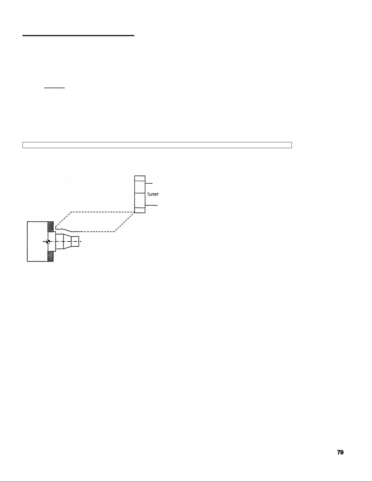
Program Zero Point - the program zero point denes a ‘relative’ X0 Z0 position with regards to the
machine’s center line. It denes the point along the machine’s center line, which in turn, correlates to
the part program’s origin.
The illustration below depicts at case which the user has dened the program zero to be at the face
of the chuck body. This ‘zero’ is often referred to as the part’s ‘Z’ zero. This point corresponds to the
programmers X0 Z0 point, or ‘origin’ in the programming process.
Note:
Fundamentally, there are two (2) methods of deciding the location of the Program Zero.
In the Okuma method, the program zero point is typically placed at the left end of the
work piece. The main advantage of this ‘style’ is that ALL programmed dimensions will by default - be positive. Additionally, there is the benet that the ‘zero’ point is effectively
represented by a physical surface of the work holder.
The other method places the program zero point at what is effectively the parts
right end. Therefore, part programs that use this ‘style’, have negative ‘Z’ program
dimensions. The decision of which method to use is mainly a matter of personal
preference.
Page 66

Coordinate Positions / Program Points
Often a cylindrical part is redrawn to show only one half of the basic part
prole, and the program points in a logical sequence. The following illustration
reects this basic technique for the part, shown above.
Page 67

G90 Absolute Positioning - this is most common method of programming. The
absolute method denes all the dimensions of the part based on parts origin point [X0 Z0]. It
is the preferred method because it simplies relating the part drawing dimensions to that of the
actual part program X, Z dimensions. The majority of engineering drawings today are based on
the ‘datum dimensioning’ technique, which, corresponds directly to absolute programming.
G91 Incremental Positioning - this method is only used when necessary. It describes the
program path based on the tool’s current coordinate in X and Z, and ‘incrementally’ denes
the next ‘target position’ relative to the actual current position. It is similar in concept to chain
dimensioning .
ABSOLUTE
Method
G50 S2000 G50 S2000
G00 X50 Z50 G00 X50 Z50
X1.25 Z3 T0101 G97S900 M03 X1.25 Z3 T0101 G97S900 M03
G01 Z2 F.015 G91 G01 Z-1 F.015
X2.5 X1.25
Z1 Z-1
X3.75 X1.25
G00 X50 Z50 G90 G00 X50 Z50
M02 M02
INCREMENTAL
Method
Page 68

PT.A
PT.B
PT.C
IDENTIFY
COORDINATES:
X Z
Page 69
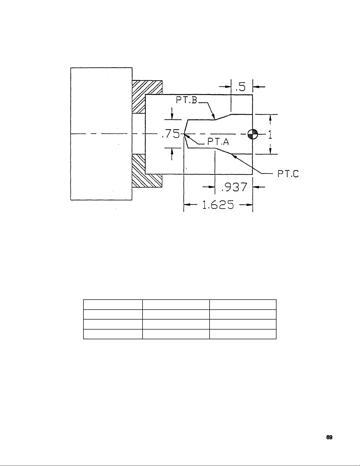
PT.A
PT.B
PT.C
IDENTIFY
COORDINATES:
X Z
Page 70

Page 71

Program Codes
G Codes
Additional G Codes
M Codes
Page 72

G Codes
Page 73

G Code Description Notes
G00 Rapid Travel Positioning
G01 Linear Interpolation
G02 Circular Interpolation (Clockwise)
G03 Circular Interpolation (Counter clockwise)
G04 Dwell, expressed as seconds (used with the “F”
format word)
G13 Designates ‘A’ Turret (upper)
G14 Designates ‘B’ Turret (lower)
G32 Fixed Threading Cycle (face)
G33 Fixed Threading Cycle (longitudinal)
G34 Increasing Lead Threading Cycle
G35 Decreasing Lead Threading Cycle
G40 Cancellation of G41 or G42 Tool Nose Radius
Compensation
G41 Tool Nose Radius Compensation (left of mate-
rial)
G42 Tool Nose Radius Compensation (right of mate-
rial)
G50 Used with ‘S’ Format Word, for Maximum spin-
dle Speed Designation
G64 Droop Control ‘OFF’
G65 Droop Control ‘ON’
G71 Longitudinal Threading Compound Cycle
G72 Transverse (end face) Thread Cutting Cycle
G73 Grooving Cycle, Feeding on the ‘X’ Axis
G74 Face Grooving/Drilling Cycle, Feeding on the ‘Z’
Axis
G75 Automatic Chamfering (45 degree corners and
llets only)
G76 Automatic Radius ( corners and llets only)
G77 Right Hand Tapping Cycle
G78 Left Hand Tapping Cycle
G80 End of Contour Denition for LAP
G81 Start of Longitudinal Contour Denition for LAP
G82 Start of Transverse Contour Denition for LAP
G83 LAP 4-High Speed Copy Turning
G84 Change of Rough Cutting Conditions in the LAP
‘G85’ Cycle
G85 Rough Cutting Cycle for LAP
G86 Copy Turning Cycle for LAP
G87 Finish Cutting Cycle for LAP
G88 Continuous Thread Cutting Program
Page 74

G Codes Description Notes
G90 Absolute Coordinate Programming
G91 Incremental Coordinate Programming
G94 Feed rate Expressed as INCHES PER MIN-
UTE
G95 Feed rate Expressed as INCHES PER REV-
OLUTION
G96 Constant Surface Footage
G97 Direct Spindle RPM Command
G110 Constant Surface Footage (cutting) - ‘A’ Tur-
ret Priority
G111 Constant Surface Footage (cutting) - ‘B’ Tur-
ret Priority
G152 Call for Programmable Tail stock
Page 75

Additional G Codes
Page 76

FREQUENTLY USED CODES
G50 Spindle Speed Limit
Power chucks are used on CNC lathes have a maximum safe RPM. This is usually stamped on the
chuck. This maximum RPM must be input on the rst line of every part program.
FORMAT:
G50 S__________
G0 Rapid Travel
Used to move the slides at full speed. Note the tool path in the G0. At rapid travel both axes move
at full speed and no linear interpolation takes place. Though the axes move simultaneously they
move individually until they reach the specied coordinate.
G0 X50 Z50: Rapid to home position for Turret Index
Set Soft Limits so that the longest tool can safely index. Also allow room for the operator to be able
to move parts from the chuck without interference with the tools in the turret. The OSP will not allow
the turret to index unless the machine is in this position
Page 77

G94 and G95 - IPR and IPM Feed
In a cutting mode, the rate by which the turret or the X-axis and Z-axis is moved, is controlled by the
“F” or feed rate word.
The mode of the “F” word is dictated by which “G” command code is chosen by the programmer.
The feedrate choices are as follows:
G94: Inches per minute
G95: Inches per revolution
The control powers up in the G95 mode, when the machine is turned on.
FEEDRATE: Fxxxx.xxx Inch per Minute
Fxxxx.xxx Inch per Revolution
Feedrate is used in conjunction with the G-codes G94 and G95 to control the rate of feed in a linear
or circular contouring mode.
Most of the programmed feedrates will be in inches per revolution; however, if inch per minute programming is needed use this formula to calculate the value:
IPM = (IPR * RPM)
ADDITIONAL USE FOR “F” WORD:
When using the G04 preparatory function the “F” word is the method used to describe dwell in
seconds
Page 78

G00 Rapid Travel Positioning - this command causes all the machines axis slides to
move at ‘full speed’ to the target position.
Note that a G00 command does not always result in a ‘straight-line’ path of motion between the
current position and the target position.
Effectively, both axes move simultaneously - (45 degree) until such time where either axis has
met its target point, and any continued axis motion is done to satisfy the remaining axis.
FORMAT: G00……Z……
N1 G00 X50 Z50
N2 X10 Z5
Notes: example performed under MDI, assumes ‘inch’ mode.
Line ‘N1” positions the turret at either of the machine’s positive stroke end limits, or the current ‘soft
limit’ positions. Main spindle rotation is not required during a ‘G00’ movement. The G00 command
becomes modal following its initial occurrence. As no tool number is ‘active’ the positioning does not
include any tool offset values. Positioning is relative to the current ‘Z’ zero offset position, and the
machine’s X and Z offset origins.
Line ‘N2’ positions the axes at X10 Z5. This line can be changed to: X10 Z5 T0101 to include the
offset value for tool number 1. Note the difference in the nal position, when including the tool offset
value.
Page 79
G01 Linear Interpolation - a fundamental program command that is used whenever ‘cutting’
takes place. A ’G01’ command requires that an associated feed rate be either contained on
the same ‘line’, or has been established prior to the G01 line. In addition, it is required that the
main spindle be rotating, that condition being established either prior to the G01 command, or
included on the same program line.
Unlike the G00 command, a G01 move will always be a ‘linear’ move. The machine’s OSP
control will always calculate the ‘X’ and ‘Z’ axis coordination, such that the tool tip will travel
from its current position, to the (G01) ‘commanded’ position in a straight line.
The length of time it takes to complete the ‘feed’ move is a function of the actual spindle RPM,
and the programmed feed rate [‘F’ Word]. The illustrations that follow depict a simple example.
FORMAT: G01 X……Z……F……
When depicting the actual tool path motion, it is customary for the rapid paths to be identied as a
dashed line, and the cutting paths to be shown as a solid line. This helps in the visualization of the
machine’s motions.
Page 80

Feed Rate ‘F’ - this ‘word’ is used to dene the desired feed per revolution during the cutting
process. It can be thought of as the amount the tool will move axially for every revolution of the
work piece.
Generally, rough turning tool feed rates range from 0.01 to 0 .02 per revolution, and nish tool
turning typically ranges from 0.004 to 0 .01 per revolution.
At the time of initial program creation, the user only needs to select an approximate feed rate
based on past experience, or cutting data tables. The optimum feed rate is ultimately tied to
the complete cutting condition, material, and chosen insert.
Examples:
G01 X Z F.010 G01 X Z F.020 G01 X Z F.004 G01 X Z F.0075
NOTE - the ‘F’ value is related to G95 or G94 selection.
♦♦♦♦
G04 ‘Dwell’ and ‘F’- occasionally there will be a need to program a dwell – or wait- directly into
the part program. Perhaps the operation of grooving might need to allow for a dwell after the
tool reaches its target position, allowing the cutting forces to relax, providing a better surface
at the minor diameter.
While the dwell command uses the ‘F’ word, it has NO association or
effect on GO1 commands containing its own ‘F’ word.
FORMAT: G04 F……
Examples:
G04 F5 G04 F0.5 G4F8 G4F8.50
Page 81

G94 - Inch Per Minute - for the most part, this mode works with the ‘F’ word when the
machine axes need to be moved at a controlled rate -AND THE MAIN SPINDLE IS NOT
REVOLVING.
An example of this would be the use of a ‘work pusher’ or the use of a bar puller.
Example:
G50 S2000
G00 X50 Z50
G00X. .. ..Z. .. . .T. .. . .
G94 G01 X. .. . .Z. .. . . . F95
G04 F1
M84
G01 Z. .. .. F40
M83
G04 F1
G01 X.. .. .Z.. . . . F95
G00 X50 Z50
G00 X. . . . .Z. . . . . S. .. ..T. .. . .M. . . . .G95
The user must assure that the part program ‘returns’ the control to the G95 mode prior to
returning the routine cutting mode.
Page 82

G95 - Inch Per Revolution - during cutting, the ‘F’ word determines the rate at which the
axis is moved. For turning equipment, the ‘F’ word is based on the unit of inch per revolution,
or IPR. Traditionally, insert manufacturers state cutting data in this IPR method.
• The OSP control powers up with G95 mode as its default, and at every occurrence of control
reset.
While it does not have to be placed into the part program, it is good practice to include a ‘G95’
at the ‘top’ of the program for ultimate authority in programming so that the program’s initial
mode is always G95.
Example:
G50 S2000
G00 X50 Z50
G00 X. . . . .Z. . . . .S . .. . .T. . . . . M . . . . .
G95 G01 X. . . . . .Z. . . . . . F. . . . . . . .
Page 83

Common M-Codes
Page 84

M Codes Description Notes
M00 Program Stop
M01 Optional Program Stop
M02 End of Program
M03 Spindle ‘ON’ Forward (clockwise)
M04 Spindle ‘ON’ Reverse (counter clockwise)
M05 Spindle ‘OFF’
M08 Coolant ‘ON’
M09 Coolant ‘OFF’
M20 Tail stock Barrier ‘OFF’
M21 Tail stock Barrier ‘ON’
M22 Thread Chamfering ‘OFF’
M23 Thread Chamfering ‘ON’
M24 Chuck Barrier ‘OFF’
M25 Chuck Barrier ‘ON’
M26 Thread Lead Along Z-Axis
M27 Thread Lead Along X-Axis
M28 Tool Interference ‘OFF’
M29 Tool Interference ‘ON’
M30 End of Program
M32 Straight In Feed: Cutting on Righ Hand Side
of Threading Tool
M33 Zig-Zag in Feed: Cutting path is Calculated
as Side to Side
M34 Angled in Feed: Cutting on Left Hand Side of
Threading Tool
M40 Spindle Gear Range - Neutral
M41 Spindle Gear Range- Selection Depends on
Machine Model
M42 Spindle Gear Range- Selection Depends on
Machine Model
M43 Spindle Gear Range - Selection Depends on
Machine Model
M44 Spindle Gear Range - Selection Depends on
Machine Model
M55 Tail stock Quill Retract
M56 Tail stock Quill Advance
M60 Spindle Speed Answer Neglect ‘OFF’
M61 Spindle Speed Answer Neglect ‘ON’ G96
Mode
M73 In Feed Pattern 1 (one) for Thread Cutting
Depths
M74 In Feed Pattern 2 (two) for Thread Cutting
Depths
Page 85

M Codes Descriptions Notes
M75 In Feed Pattern 3 (three) for Thread Cutting
Depths
M83 Chuck Clamp
M84 Chuck Unclamp
M86 Turret Indexing Direction: Clockwise
(Reverse)
M87 Cancel M86 (Forward)
M88 Air Blower ‘ON’
M89 Air Blower ‘OFF’
M90 Door (cover) Close
M91 Door (cover) Open
Page 86

Page 87

Program Format and Data Word/Address
(letter/number combinations)
Refer to LB25-T min Program at Front
Begin with Simple Examples; T-Command Will
be Covered in Detail Later
Discuss comments inside Parentheses
Page 88

Basic Program
The following program example uses the program points from the proceeding part example.
G50 S2000
G00 X50 Z50
X0 Z3.1 T0101 G97S975 M03 M08
G01 Z3 F.01
X1
X1.25 Z2.875
Z2
X2
X2.5 Z1.75
Z1
X3.75 + .1
G00 X50 Z50
M02
N001 G50 S2000
N005 G00 X50 Z50
N010 X0 Z3.1 T0101 G97S975 M03 M08
N020 G01 Z3 F.01
N025 X1
N030 X1.25 Z2.875
N035 Z2
N040 X2
N045 X2.5 Z1.75
N050 Z1
N055 X3.75 +.1
N060 G00 X50 Z50
N065 M02
← Max. Spindle RPM
← Rapid to Home/ Index Position
← Approach Move, select tool speed
← Feed to “A”
← Feed to “B”
← Feed to “C”
← Feed to “D”
← Feed to “E”
← Feed to “F”
← Feed to “G”
← Feed to “H” and off part
← Rapid to home
← End of Program
Line Numbering – for ease in identifying
a specic line within a part program, the
program can accept a “N” word and up to 4
trailing alphanumeric characters.
This illustration depicts applying “line
numbering” to the above program example
In addition to this the sequence line
numbers are used when a “program restart”
is performed.
Page 89

S,T,M Execution - all S, T, M words which are part of any ‘program block line’ will always be
executed on a ‘rst priority’ level of hierarchy.
In the preceding example, the M08, M03, S650, and T0101 will ALL be
‘established’ before the machine slides are allowed to move to the
commanded position.
The order in which the S, T, or M words are placed on a program line are not critical, but it
must be possible for the OSP control to execute them in the specic order.
Depending on the programmers ‘Style’, the following examples are given
to show the many possibilities for a simple program.
G50 S2000
G00 X50 Z50
G00X3 Z8.2 T0101 G97 S650 M3 M8
G01 Z6 F.012
G01X4 Z4
G01Z2
G01X5.1
G00 X50 Z50
M02
G50 S2000
G00 X50 Z50
T0101
G97S650
M3M8
X3 Z8.2
G01 Z6 F.012
X4 Z4
Z2
X5.1
G00 X50 Z50
M02
G50 S2000
G00 X50 Z50
X3 Z8.2 T0101 G97 S650 M3 M8
G01 Z6 F.012
X4 Z4
Z2
X5.1
G00 X50 Z50
M02
G50 S2000
G00 X50 Z50
X3 Z8.2 T0101
G97 S650 M3 M8
G01 Z6 F.012
X4 Z4
Z2
X5.1
G00 X50 Z50
M02
The style of programming is virtually limitless. As long as the program ‘code’ is presented in an
executable order, the control will accept any programming style.
Page 90

Spindle Ranges
Depending on your machine type, the headstock unit may have up to four (4) ranges. There are
different methods that allow the headstock to change from one range to another. Please research
your machine type to determine if your programs need to contain all the fundamental ‘M’ codes
relating to spindle ranges.
Ranges: M41, M42, M43, M44
The smaller to moderate machines have the ability to change ranges ‘on the y’. Therefore, the
spindle does not come to a stop, and higher productivity is the end result.
As a programmer, this requires knowledge of the torque / horsepower available for a given (spindle)
range. The following charts are representative information that SHOULD BE REFERENCED PRIOR
to setting a cutting condition or process.
For heavy-duty cutting, select a spindle speed in the—— area so that cutting is performed within a
constant output range.
Low speed/high speed range is changed by VAC motor coil connection (takes approx... 1 sec.)
Page 91

Tool Selection Command - this command allows part program to select the desired tool to be
indexed into the cutting position.
For reasons of clarity, a tool number is synonymous with a turret station number. The tool is
identied by using a ‘T’ word, and trailing digits.
Formats
T_ _
T_ _ _ _
T_ _ _ _ _ _
Ultimately, the command can consist of up to 3 pairs (6 digits) of data for a complete tool
description.
Depending on the tool type being utilized, not all 3 pairs of data be present.
The following examples depict various ‘T’ word scenarios.
G50 S1000
G00 X50 Z50
X10 Z10 T0100
This program containing ‘T0100’ allows for tool #1
to be placed at the cutting position, BUT, does not
‘read’ the number #1 tool’s X and Z offset values when
positioning to ‘X10 Z10’. Therefore positioning will be
based on current machine origin offsets. The turret
body is placed at the commanded position, and not
the cutting tool itself.
Page 92

G50 S1000
G00 X50 Z50
X10 Z10 T010101
This program, containing ‘T010101’ allows tool
#1 to be placed at the cutting position, reads the
number #1 tools X and Z offset values, and reads,
the corresponding X,Z nose radius values. Programs
that utilize the tool nose radius function, require a
corresponding fully described tool (all data elements).
Failure to dene the tool’s nose radius register #, will
disable TNR function (correction) cutting.
G50 S1000
G00 X50 Z50
X10 Z10 T0101
The following illustrates the fundamental positions of an ‘offset’, as well as depicts some common
tools that typically require more than one offset to simplify program creation. Independent offset
control is a simple means of controlling a part features nal size.
This program, containing T0101 allows for tool #1
to be placed at the cutting position, and in addition,
reads the number #1 tool’s X and Z offset values when
positioning to X10 Z10. Therefore positioning will be
based on the machine zero offsets, and the X, Z tool
offsets.
Tool position is correct.
Page 93

Problems
1. What is the difference a G90 and a G91 code?
2. What are the two primary axis of a lathe?
3. G00 causes the axis slide to move, how?
4. What are the two uses of the “F” word?
5. What is the difference between the G94 and the G95 codes and how do they affect the “F”
word?
6. What word do you use for line numbering?
7. What is the importance of the “S”, “M”, “T” words?
Page 94

8. What is the word used for tool?
9. How many “pairs” will it take to dene tool number and offset number?
Page 95

ANGLE COMMAND
Page 96

1. What are the angles for each circle?
2. When a tool is designated as a 4-place number, what are the meaning of the numbers?
3.
Will the tool nose compensation be picked up by the control with a 4-place
designation? Explain.
Page 97

Page 98

Page 99

CIRCULAR INTERPOLATION
Write Simple Program on Board Part DR202-3
Eliminate Speed and gear range
Write program with zero at front and back
Write Program on Board for DR201-3
Have a student key in the program on simulator as you write
Add graphics commands to program, without explanation to students
Call Up and Test Program
Review
Page 100

Circular Interpolation
Circular interpolation uses either a “G02” or “G03” command to allow the machining of arcs or radii
either external or internal.
Fundamentally, an arc has a direction based on the advance of the cutting tool. An arcs direction is
said to be either clockwise or counterclockwise in determining its program format.
FORMAT: G02 or G03 X.....Z...I +-.......K+-.........((L) option)......
While using a G02 or G03 command is not always mandatory to generate arcs, radii, or spherical
features, this command is routinely used in manual programming, and virtually universal in its format
to all CNC programming.
While the OSP control has other simplied programming methods to meet the needs of many circular
features, the G02 and G03 commands can always handle the most complex of proles.
The following illustrations depict various arc’s and their corresponding direction. Understanding the
arc’s direction is a fundamental root level of knowledge for the programmer.
After the direction of the arc is dened, it is now necessary to dene both the start point, or origin of
the arc, and the end point of the arc.
Please note that the actual G02/G03 program command uses the X and Z words for the end point of
the arc. HOWEVER, the above start points must be known such that the program line immediately
prior to the G02/G03 command positions the cutting tool correctly.
 Loading...