

OKIDATA ML1120 Maintenance Manual
6
5
4
No.01
Oki Data CONFIDENTIAL
ML1120 PRINTER
Maintenance Manual
3
Related drawings
Drawing No. Name
43471801TL ML1120 Disassembly for Maintenance
2
43471801TR ML1120 RSPL
43516901TM ML1190 Troubleshooting Manual
[Rev. 1]
BOM Use for Certification Body
Rev Date DCO No. Contents Design Approval
1 2004-05-21 HP9-0009 Change format Tomoyo Sugiyama Akio Kikuchi
1
Approval
.....................................................................................................
Check
.....................................................................................................
Date
Yoshifumi Igari Yoshifumi Igari
Yoshifumi Igari
2006-10-10
Design
Name
ML1120
Maintenance Manual
Drawing No.
43471801TH
1
83
Document Revision History
Oki Data CONFIDENTIAL
Rev.No. Date
No.
1 2006-10-10 ISSUE ODS Y. Igari
Corrected items
Page Description of change
Person in
charge
43471801TH Rev.1 2 /

Oki Data CONFIDENTIAL
PREFACE
This maintenance manual describes how to maintain the ML1120 printer in the field.
This manual is for customer engineers.
For further information, refer to the Users Manual for handling or operating the equipment.
43471801TH Rev.1 3 /

Oki Data CONFIDENTIAL
Contents
1. CONFIGURATION .............................................................................................. 6
1.1 Standard Printer Configuration ............................................................................................ 6
2. OPERATION ........................................................................................................7
2.1 Summary.............................................................................................................................. 7
2.2 Circuit Operation (See Figure 1) .......................................................................................... 8
2.2.1 CPU and peripheral circuits .................................................................................... 8
2.2.2 Initializing operation .............................................................................................. 10
2.2.3 Controlling the interface ........................................................................................ 10
2.2.4 Print head control drive circuit .............................................................................. 10
2.2.5 Spacing ................................................................................................................. 11
2.2.6 Line feed ............................................................................................................... 11
2.2.7 Alarm circuit .......................................................................................................... 11
2.2.8 Paper-end detect circuit ........................................................................................ 11
2.2.9 Power source unit ................................................................................................. 11
2.3 Mechanical Operation ........................................................................................................ 12
2.3.1 The Printhead Mechanism and Its Operation (see figure 2) ................................. 12
2.3.2 Mechanism and operation of space (see figure 3) ................................................ 13
2.3.3 Mechanism for adjusting the head gap (see figure 4) ........................................... 14
2.3.4 Mechanism and operation of ribbon feed (See figure 5) ....................................... 15
2.3.5 Paper Feed Operation .......................................................................................... 16
2.3.6 Paper Detection Mechanism ................................................................................ 23
2.3.7 Automatic Sheet Feed (See Figure 14.) ............................................................... 25
2.3.8 Paper Park Function (Continuous paper) ............................................................. 27
3. ASSEMBLY/DISASSEMBLY ..............................................................................28
3.1 Precaution for Parts Replacement ..................................................................................... 28
3.2 Service Tools29
3.3 Disassembly/Reassembly Procedure ................................................................................ 30
3.3.1 Ribbon Protector ................................................................................................... 32
3.3.2 Printhead ............................................................................................................... 33
3.3.3 Pull-up Roller Assy ................................................................................................ 34
3.3.4 Upper Cover Assy, Access Cover Assy and Sheet Guide Assy ........................... 35
3.3.5 Platen Assy ........................................................................................................... 36
3.3.6 Printer unit ............................................................................................................. 37
3.3.7 Carriage Cable, Homing sensor ............................................................................ 38
3.3.8 Idle-pulley .............................................................................................................. 39
3.3.9 Ribbon Feed Assy. ................................................................................................ 40
3.3.10 Stepping Motor (Space) ........................................................................................ 41
3.3.11 LF Motor................................................................................................................ 42
3.3.12 Gap Sensor Cable, Gap SW and continuous-form/cut-sheet SW ........................ 43
3.3.13 Slider Pice-Slider .................................................................................................. 44
3.3.14 Mini Pitch Belt ......................................................................................................... 45
3.3.15 Paper Pan Assy, Roller Assy ................................................................................ 46
3.3.16 Bottom sensor, photo interrupter and sensor cord (6P) ........................................ 47
3.3.17 Operation Panel Board and Operation Panel cord ............................................... 48
3.3.18 Control Board Assy. ................................................................................................ 49
3.3.19 Power supply Assy................................................................................................ 50
43471801TH Rev.1 4 /

Oki Data CONFIDENTIAL
4. ADJUSTMENT ................................................................................................... 51
4.1Gap between platen and print head ....................................................................................... 52
4.2Paper top positioning distance check ..................................................................................... 53
4.3Correcting cut-sheet 40-line feed height ................................................................................. 55
4.4Correcting both-direction print registration ............................................................................. 56
4.5Paper cut position check ........................................................................................................ 57
5. CLEANING AND LUBRICATION ....................................................................... 59
5.1 Cleaning ............................................................................................................................. 59
5.2 Lubrication ......................................................................................................................... 60
6. TROUBLESHOOTING AND REPAIR ................................................................66
6.1 Items to Check Before Repair ............................................................................................ 66
7. PROGRAM UPDATE76
7.1 Prepare to amount the ROM76
7.2 Creating EPROM for rewriting flash memory and installing it. ........................................... 76
7.3 Operation to start flash download. ..................................................................................... 77
7.3.1 Execution of the rewite operation .......................................................................... 77
7.3.2 Operation Check ................................................................................................... 78
7.4 Initial condition ................................................................................................................... 78
8. PARTS REPLACED PERIODICALLY ................................................................79
APPENDIX A PCB LAYOUT ....................................................................................80
APPENDIX B CIRCUIT SYMBOLS..........................................................................82
43471801TH Rev.1 5 /
1. CONFIGURATION
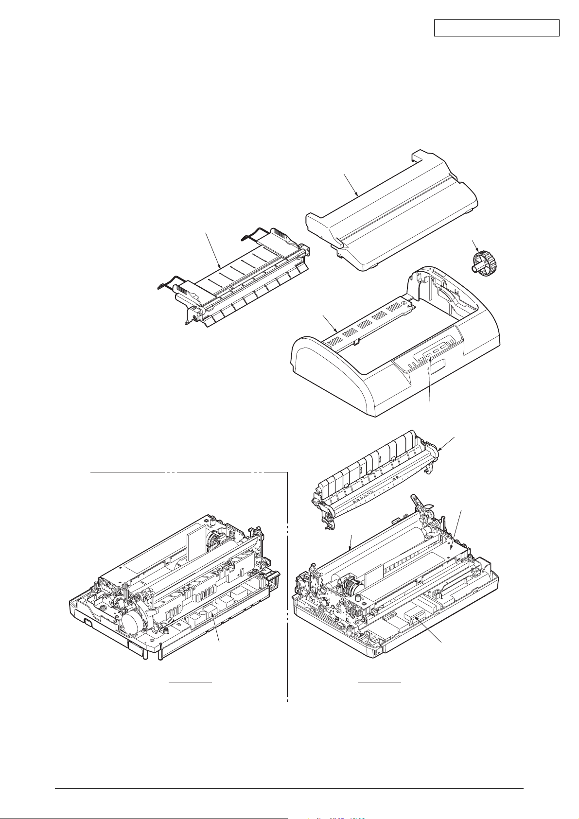
1.1 Standard Printer Configuration
The standard configuration of the ML1120 is as follows:
Oki Data CONFIDENTIAL
Access cover assy
Sheet guide assy
Platen Knob
Upper cover
Operation panel assy
Pull-up roller assy
Ribbon cartridge
Print unit
Rear View
Power Supply board
Fuont View
Control board
Figure 1-1. Printer Configuration
43471801TH Rev.1 6 /

Oki Data CONFIDENTIAL
2. OPERATION
2.1 Summary
The main configuration of this printer is the print mechanism unit and print control unit.
The print mechanism unit can be divided broadly into the print head, space system, paper-feed system,
and ribbon-feed system. The operation of each item is listed below.
(1) Print head ........................... Prints with the 9 wire-dot magnet. The dot patterns are configured
in the print control unit.
(2) Space system ..................... The stepping motor moves the carriage and performs spacing,
tab, and carriage return.
(3) Paper-feed system.............. Paper is feed by the stepping motor.
(4) Ribbon-feed system ............ Ribbon is feed by obtaining drive force from the stepping motor
just as in the space system.
(5) Print control unit .................. Controls the interface and mechanism with one MSM67 × 640
microprocessor (µCPU).
43471801TH Rev.1 7 /

Oki Data CONFIDENTIAL
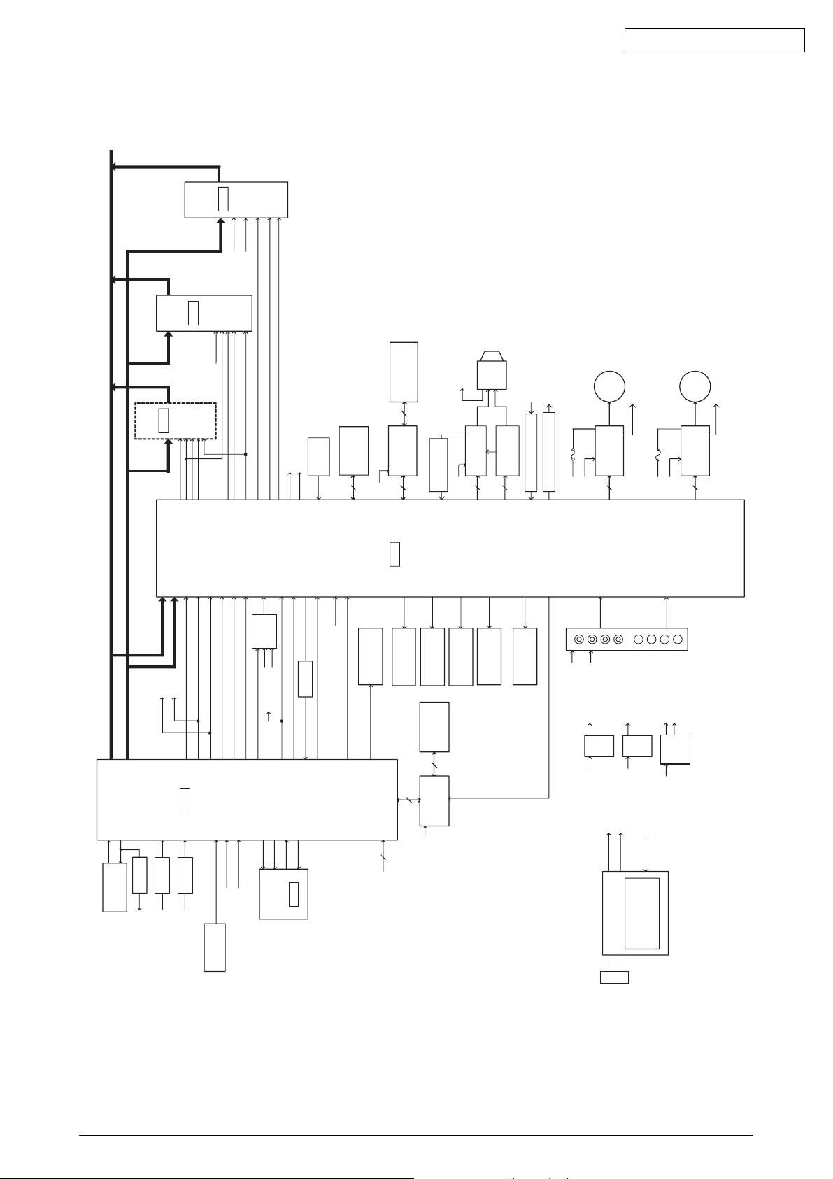
2.2 Circuit Operation (See Figure 1)
The circuit of this printer consists of the control board and carriage board.
Circuits such as µCPU and its peripheral circuits, drive circuits, and the external interface circuit are set
on the control board.
The switches and LED are set on the control board.
With the control board being the main board, the boards are connected by cables.
2.2.1 CPU and peripheral circuits
(1) CPU (MSM67 × 640)
The CPU is a 16-bit one-chip CPU which operates the peripheral circuits. Each I/O port is set
as ADDRESS - BUS, DATA - BUS, and various control lines. It is capable of 4-channel A/D
converter input and has five timers.
(2) Program ROM (Flash ROM)
The control program of the printer is stored. µCPU operates according to the contents and
various controls are performed.
(3) Printer Butter etc (D-RAM)
This is used to store various data for data received in 4Mbit RAM or print buffer, etc.
(4) LSI (MG74Q514-131)
This is an LSI exclusively for the print head controller, external interface, and motor control. It
has the following functions.
(a) Print head data control
Print data is unarchived to the print timing of a disperse allocation head and controls 24-pin
worth of impact data drive time.
(b) Dot timing generating function
Dot timing (IPT) in sync with the print speed is generated and notifies the information to
CPU.
(c) Speed control function of the space motor
The speed of the space motor is controlled and input command from CPU. Furthermore,
the space motor speed in various print modes are also controlled.
(d) Parallel interface function
IFD 1-8 are used as input/output data of parallel data. Parallel data sent from the interface
connector is latched by strobe signal STB-N and is read into CPU by a RD signal.
Furthermore, control signals such as BSY-N, ACK, PE-N, and SEL-N are output to the
interface connector by WR signals.
(e) I/O port
The I/O port has 14-bit input/output ports and controls various signals by input command
from CPU.
(5) Download ROM (EPROM)
Use when update the Flash-ROM program. Usually nonimplement.
43471801TH Rev.1 8 /
CPU
MSM67X6
40
LSI
2
18
20
14
SP Driver
+35V
7
LF Driver
5
8
Switching Power
Supply
Overvoltage/
overcurrent
Detector circuit
+5V
+35V
AC IN
REG
IC
+3.3V
RESET
IC
4
1
RESET
EP-ROM
(16Mbit)
20MHz
OSC
XTL1
XTL2
Power
Contror
+5VH
5.0V
5.0V
3.3V
RX
D
IPT-N
CLKP10
ADI1
ADI0
PSEN
PSEN
PSEN
A19
CS1
P01
LSICS(CS3)
P04
LSICSN
RSTN
CAS
D-RAM
(4Mbit)
5.0V
IR1
IR0
IPT
9
9
STN1
AFN1
IPN1
SIN1
BSY1
AKN1
SLP1
FTN1
PEP1
IFDIR
SPAPH
SPENB-AS
SPDCYA
SPBPH
SPENB-BS
SPDCYB
SPREF1
SPREF2
LFENBA0
LFENBA1
LF-PHA
LFENBB0
LFENBB1
LF-PHB
LFREF1
SW
EEPROM
(4kbit)
P1
7
P1
4
P1
2
EEDIN
P1
3
5.0V
RDN
CLK
CS0
FL2C
P03
RAS
5VH
5V
+35V
Buffer
Buffer
FLASH-
ROM
(8Mbit)
5.0V
P11
P05
P06
4
FL1BYT
FLAM-1
Buffer
ALMIN2,3
ALMIN1
1
FG
ADI3
ADI2
RAS
3
(ALMIN4,5,6)
Home Position
Sensor
SWI4
SWI1
SWI5
SWI3
SWI2
RAS
Buffer
Temperature
sensor
CS0
P00
CS2
CS2
ALM
ALM
ALM
P02
Buffer
WR
D00
‘
D15
WE
OE
BYTE
CE RAS
OE
UCAS
LCAS
RAS
BYTE
CE
OE
A19
MG74Q514-131
Alarm Circuit (IN)
Alarm Circuit (Out)
Operator Board
Program ROM
CLK
A00
‘
A19
3.3V
¤
5.0V
3.3V
¤
5.0V
HTEMP-N
DCLOW
RD
EECS
EEDOUT
EECLK
P16
P17
A00
‘
D00
‘
D15
DRL
RD
LWR
RAS
LSIRST
BREQ
BACK
WRH
RD
WRL
LPG
WR
3.3V
¤
5.0V
TXD/RXD/DSR/CTS/CD
Serial I/F
Driver
Serial I/F
Connector
Bottom PE
Sensor
Paper SelectPE
Sensor
Head Gap 2
Sensor
Head Gap 1
Sensor
Paper Select
Micro SW
LED
+5V
D15ZA-1
D15ZA-1
WRL
RD
Print Buffer etc
ALMOUT
+5V
+5V
+5V
RESET
+5VD
SP
Motor
LF
Motor
5VH
USB
Connector
OSC
48MHz
Pararel I/F
Connector
Alarm Circuit
(IN
j
Head Driver
(DT1)
Head Driver
(DT2)
9pin
Head
HTEMP
Pararel I/F
Driver IC
RXD
CASH
CASL
5V
IF11
‘
IF18
5VH
ALMOUT
ALMOUT
FLRS
DFL2BY
FLA19TE
FL1CSE
DRAMWR
CASH
CASL
SPENB-A0
‘
SPENBA2
SPENB-B0
‘
SPENB-B2
SWC1
‘
4
LED1
‘
4
RTS/SSD/DTR
WRN
DCASN
BACKP
BREQP
DWRHN
Oki Data CONFIDENTIAL
43471801TH Rev.1 9 /
Figure 1
Oki Data CONFIDENTIAL
2.2.2 Initializing operation
The initializing operation is performed for this printer when the power is turned ON and when I-PRIME for
the parallel interface is input from the Host.
In the initializing operation, the RST-N signal is first output from the reset IC (RST-1 pin) to reset CPU.
The program start after CPU is reset.
The program sets the LSI mode including CPU, checks the memory (ROM/RAM), and initializes the
RAM. Then it determines the phase of the LF motor and performs homing for the carriage. Finally, it
determines the interface signal (outputs ACK signal and BUSY signal), illuminates the A lamp, notifies
the Host that it is in a mode that can receive data (data standby mode), and completes initialization.
(Paper-end mode when using continuous form is excluded.)
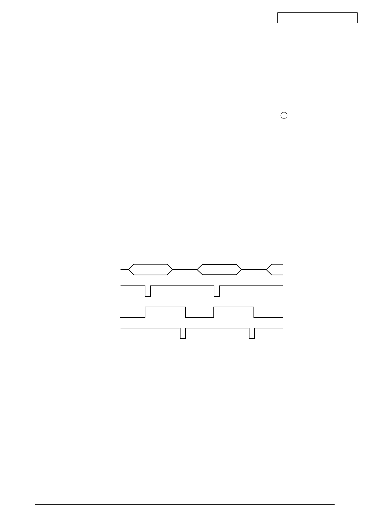
2.2.3 Controlling the interface
1) Parallel interface
Data from the interface is input from the connector (CENT) and is read in the timing of the
STB-N signal by the interface, print head, and LSI for motor control (MG74Q514-131).
When this signal is being process, the BUSY signal goes ON. When the process is completed,
the BUSY signal goes OFF, sends an ACK-N signal, and waits to receive the next data.
(E.g.) When [I/F timing] is set to [A-B] in an English menu.
DATA1~8
STROBE-N
BUSY
ACK-N
2.2.4 Print head control drive circuit
This circuit produces the print timing and drive time from LSI, drives the head magnet that corresponds to
HEAD 1~9 with HD01-09-P signal and HDCOM1~9 - P signal and prints.
As the print head is dispersed and allocated in each group, the nine groups are controlled individually.
43471801TH Rev.1 10 /

Oki Data CONFIDENTIAL
2.2.5 Spacing
The LSI (MG74Q514-131) outputs space motor phase signals (SP_PHA,SP_PHB) when it receives a
spacing command from µCPU. It outputs IPT signals as the dot timing and carriage position detection
timing in sync with these phase signals.
The space motor phase signals (SP_PHA,SP_PHB) are input to the motor driver, which drives the space
motor.
SH_PHA
Motor driver input
SP_PHB
2.2.6 Line feed
The LF motor phase signals (LF_PHA, LF_PHB) from LSI (MG74Q514-131) are input to the motor driver,
which drives the LF motor.
LF_PHA
Motor driver input
LF_PHB
2.2.7 Alarm circuit
(1) High-temperature head alarm
The temperature of the head is monitored by a thermistor embedded in the head to protect the
head coil.
The head temperature will rise after continuous heavy-duty print jobs. Therefore, when the
head rises beyond a specified temperature, a thermal alarm mode will be entered, and after the
current line is printed, the speed for printing the following lines will be decreased. Furthermore,
if the head temperature does not fall, the following lines will be divided into two depending on
the temperature, and printed by single-direction print.
The alarm is detected when the resistance of the thermistor decreases from the rise in the
head temperature and CPU is input in the A/D converter.
2.2.8 Paper-end detect circuit
When paper runs out, the photosensor (PE) goes Hight level and the paper-end signal becomes 1. This
signal is input in CPU which goes on the B lamp.
2.2.9 Power source unit
The power source unit supplies DC+35V and +5V to each section by switching power.
43471801TH Rev.1 11 /
2.3 Mechanical Operation
2.3.1 The Printhead Mechanism and Its Operation (see figure 2)
The print head is spring-loaded, utilizing a permanent magnet, and can be easily removed or
installed. The print head is mounted on a carriage that runs parallel to the platen and is
connected with the control circuit via the head board.
The print head consists of:
(a) Wire guide
(b) Print wires
(c) Armature assembly
(d) Yoke
(e) Springs
(f) Spacer
(g) Magnet assembly
(h) Thermistor
(i) Printed-circuit board
(1) Print head operation
Oki Data CONFIDENTIAL
When the print head is in the non-printing state, each armature is attracted by the
permanent magnet, and the springs holding the armatures are compressed by the thickness of the spacer, The print wires, which are fastened to the individual armatures, are
therefore held retracted within the wire guide.
When signals corresponding to a character to be printed are detected by the control circuit,
currents flow through the corresponding coils to nullify the magnetic flux generated by the
permanent magnet between the armatures corresponding to those coils and the permanent
magnet pole. As a result, those armatures are driven toward the platen by the force of
the armature springs, and the print wires fastened to those armatures eject from the tip
of the wire guide and strike the paper through the ribbon to print dots on the paper.
After the character is printed, the magnetic flux of the permanent magnet attracts the
armatures again so that the print wires retract into the wire guide.
The print head has a built-in thermistor to prevent the coils from overheating and burning
due to continuous bi-directional printing over a long period. If the coil temperature exceeds
the limit (approximately 100 degrees C), the control circuit detects the thermistor signal
and stops the printing operation until the coil temperature drops below the limit.
Paper
Ribbon
Print wire
Amature assembly
Thermistor
Core
Wire guide
Yoke Magnet coil
Figure 2
43471801TH Rev.1 12 /

2.3.2 Mechanism and operation of space (see figure 3)
The space mechanism of printers consists of several parts, including a carriage shaft placed
parallel to a platen and a carriage frame that moves along the carriage shaft. The space
mechanism is driven by a space motor located behind the carriage frame.
The space mechanism consists of:
(a) Stepping motor with motor gear
(b) Carriage frame
(c) Carriage shaft
(d) Carriage position sensor
(e) Slide rail
(1) Spacing operation
A carriage carrying a print head moves on its shaft parallel to a platen. As a space motor
revolves, the power of the space motor is transferred to a mini pitch belt. This completely
moves the carriage. The position of the carriage frame is detected by the left-hand carriage
position sensor.
Oki Data CONFIDENTIAL
Print head
Platen
Carriage shaft
Slide rail
Space motor
Mini pitch belt
Carriage frame
Carriage frame
Carriage position
sensor
Figure 3
43471801TH Rev.1 13 /
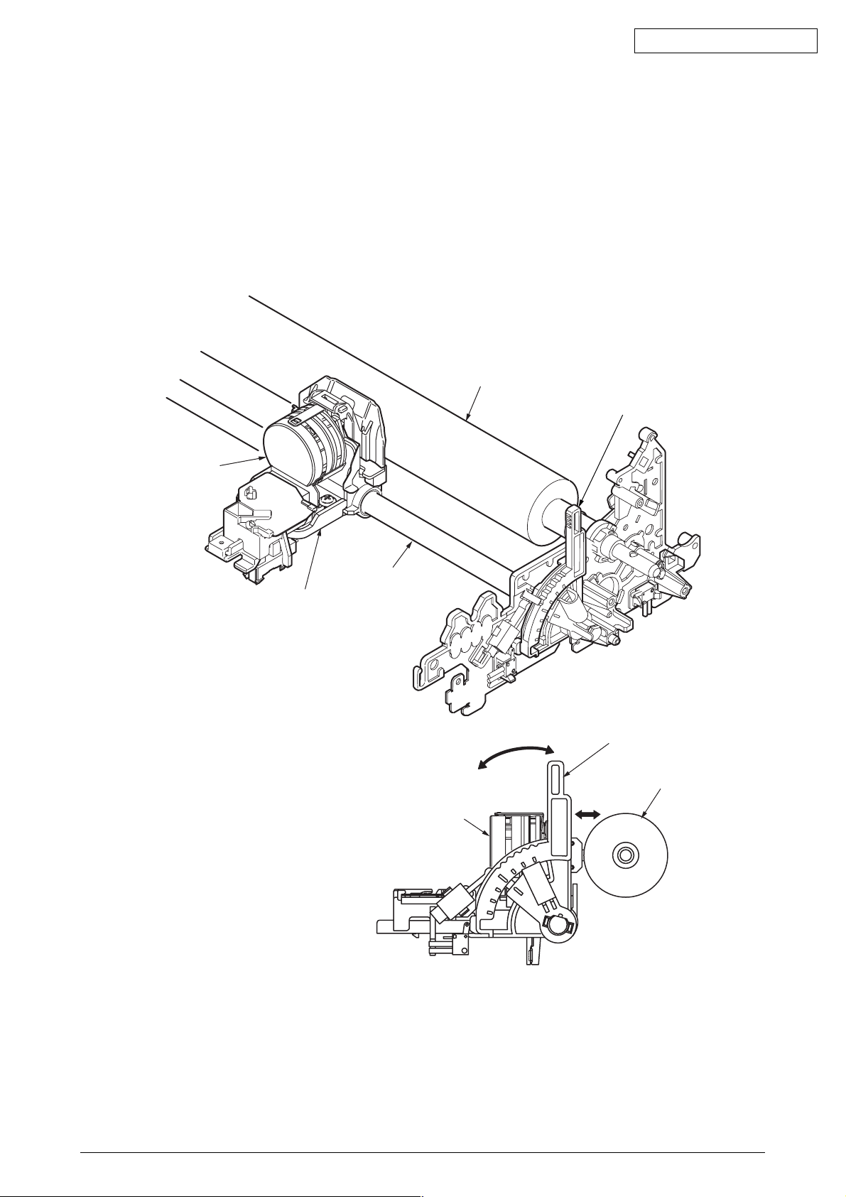
2.3.3 Mechanism for adjusting the head gap (see figure 4)
The head gap adjustment is a mechanism to correct the gap between the print head and platen
by moving the adjust lever vertically and rotating and moving the carriage shaft toward and away.
The movement of the adjust lever rotates the carriage shaft that is connected directly to the
adjust lever.The carriage shaft is decentered against the fulcrum of the adjust lever (section fit
with the carriage shaft), therefore, the carriage shaft moves towaed and away when the adjust
lever rotates. The print head then moves towaed and away the platen.
Platen
Oki Data CONFIDENTIAL
Adjusting lever
Print head
Carriage frame
Carriage shaft
Print head
2
1
2
Adjusting lever
Platen
1
Figure 4
43471801TH Rev.1 14 /
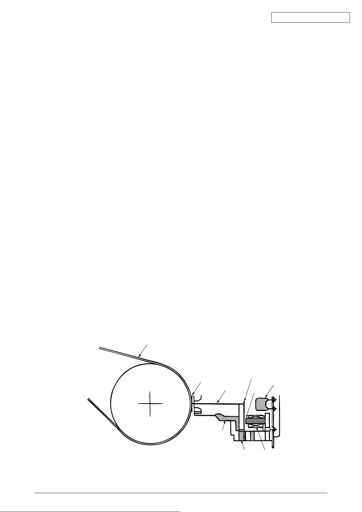
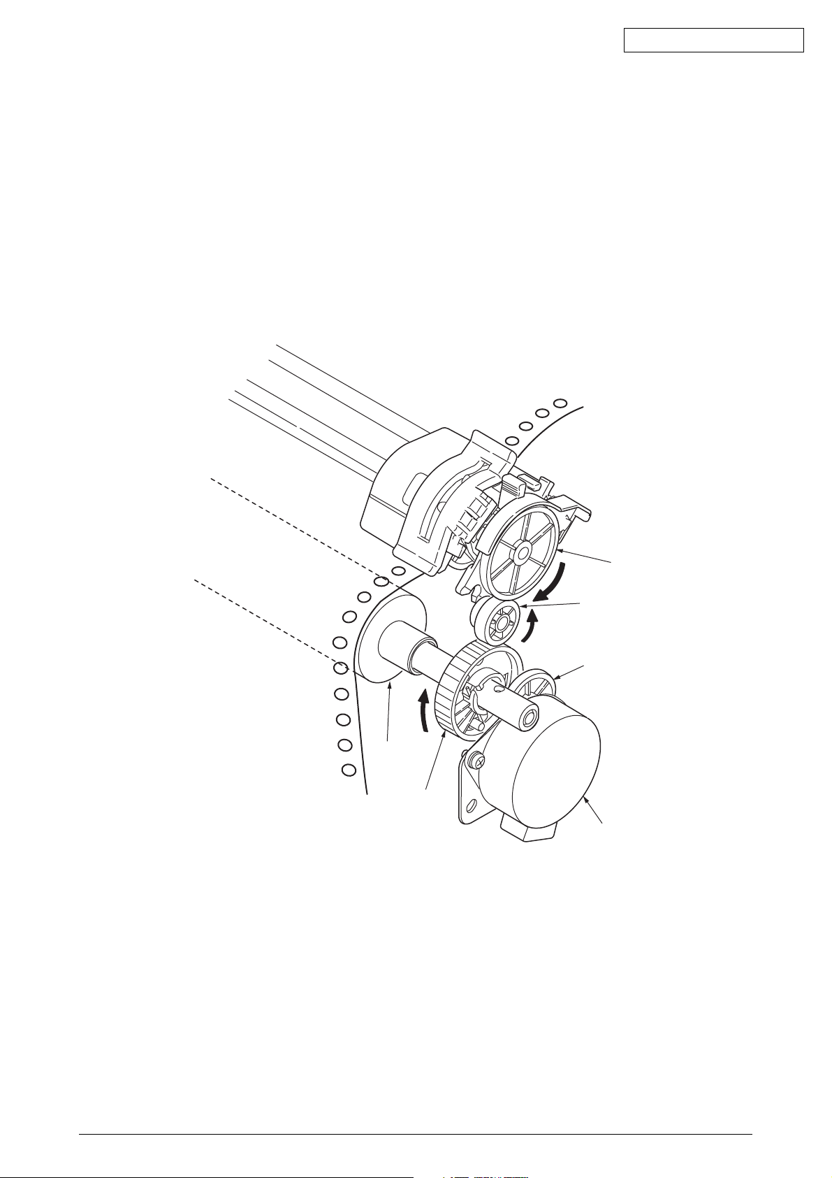
2.3.4 Mechanism and operation of ribbon feed (See figure 5)
Ribbon feed is a mechanism to feed the ribbon which is driven by the stepping motor.
The ribbon feed mechanism consists of:
(a) Ribbon feed gear assembly
(b) Ribbon cartridge
1) Ribbon cartridge
The use of a one-way feed endless ribbon provides clear print results.
(2) Feed operation
Ribbon feed is initiated at the same time the spacing operation is initiated regardless of the
mode, and stops when the spacing operation is ceased.
The rotation of a driven stepping motor is transferred to the drive roller in the ribbon cartridge
via the ribbon gear which feeds the ink ribbon.
Ribbon cartridge
Drive roller
Oki Data CONFIDENTIAL
Ribbon drive gear
Ribbon drive gear
Idie gear
Figure 5
43471801TH Rev.1 15 /

2.3.5 Paper Feed Operation
Feeding of the paper is performed by turning the platen and the pin tractor, which is driven by
the LF stepping motor.
Item of the paper feed mechanism are as follows:
(a) Stepping motor with gears
(b) Decelerating gear
(c) Platen
(d) Tractor feed unit
(e) Pressure roller
Oki Data CONFIDENTIAL
43471801TH Rev.1 16 /
Oki Data CONFIDENTIAL
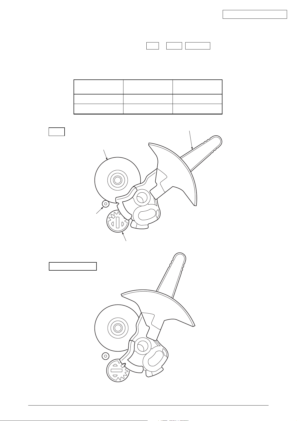
(1) Cut sheet and continuous sheet switching mechanism (See Figure 6.)
Three different paper paths can be selected and set by the change lever.
(a) TOP (Cut-sheet mode)
To use cut-sheet paper in manual mode, turn the change lever to the “TOP” position to
enter cut-sheet mode.
[Operation]
Turning the change lever to the “TOP” position moves the change gear and disengages
this component from the tractor gear.
Driven by the LF motor, the idle gear rotates and transmits this rotation to the platen gear.
The pressure rollers (front/rear) are pressed to the platen to feed the cut-sheet paper.
At the same time, the change lever activates “TOP-REAR_SW,” conveying to the control
board that the change lever is in the top position and that the cut-sheet mode is selected.
In cut-sheet mode, after paper has been set in position and the specified time stored in the
menu has elapsed, the paper is fed automatically into the start position.
(b) REAR (Continuous-form: The push tractor is placed in the rear.)
When the change lever is in the rear position, the change gear is engaged with the tractor
gear and the rotation of the LF motor is transmitted to the tractor gear via the idle gear and
the change gear.
The rotation of the tractor gear rotates the tractor shaft, which in turn feeds the continuous-
form set in the push tractor.
At the same time, the change lever turns off “TOP-REAR_SW,” conveying to the control
board that the change lever is in the rear position and that continuous-form mode is selected.
(c) BOTTOM (Continuous-form: The tractor is placed above the platen.)
The rotation of the LF motor is transmitted to the tractor gear via the idle gear, the platen
gear, and the pull-up gear.
The rotation of the tractor gear rotates the tractor shaft, which in turn feeds the continuous
form set in the pull tractor.
At the same time, the change lever turns off “TOP-REAR_SW,” conveying to the control
board that the change lever is in the rear position and that continuous-form mode is selected.
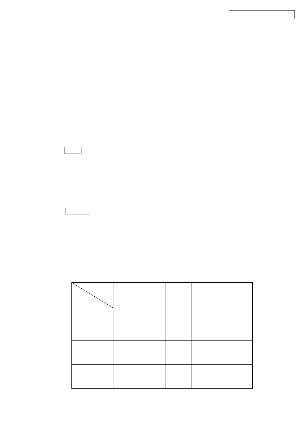
Correlation in Mechanism
Mechanism
Lever
Position
TOP
REAR
BOTTOM
43471801TH Rev.1 17 /
Top
Rear
change
Switch
OFF
ON
OFF
Idle
Gear
Rotate
Rotate
Rotate
Change
Gear
Rotate
Rotate
Rotate
Tractor
Gear
Stop
Rotate
Stop
Sheet
Insertion
Manual/
automatic
•
Operation
SW
or
•
instruction
•
Operation
SW
or
•
instruction
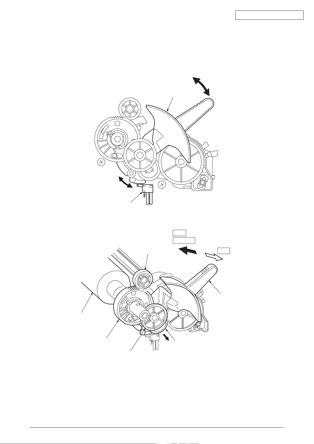
Change lever
Oki Data CONFIDENTIAL
Platen
Top-Rear changswitch
Platen gear
Idle gear
Pull up gear24
Rear
BOTTOM
TOP
Change lever
Change gear
Figure 6
43471801TH Rev.1 18 /
Oki Data CONFIDENTIAL
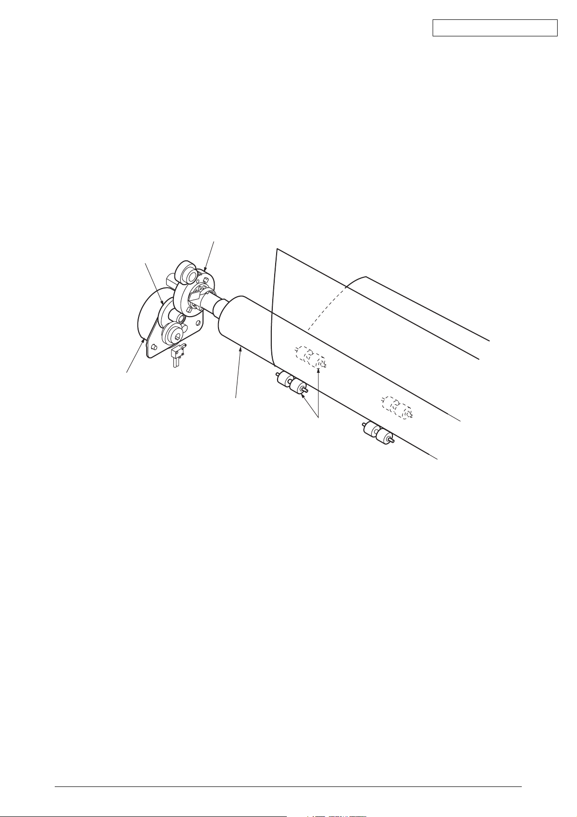
i2) Cut-sheet feeder operation (See Figure 7.)
The pulse motor used for the paper feed mechanism is mounted on the left of the frame,
and the rotation of the motor is transmitted through decelerating gears (LF idle gear, platen
gear) to the platen. When using cut-sheet paper, the change lever must be in the TOP
position to grab the paper, while disengaging the push tractor.
When the change lever is set to the TOP position, the cut sheet is automatically fed
in up to the print start position after pausing for the wait time stored in the menu.
Platen gear
Idel gear
Stepping motor
(LF motor)
Platen
Pressurp roller
Figure 7
43471801TH Rev.1 19 /
Oki Data CONFIDENTIAL
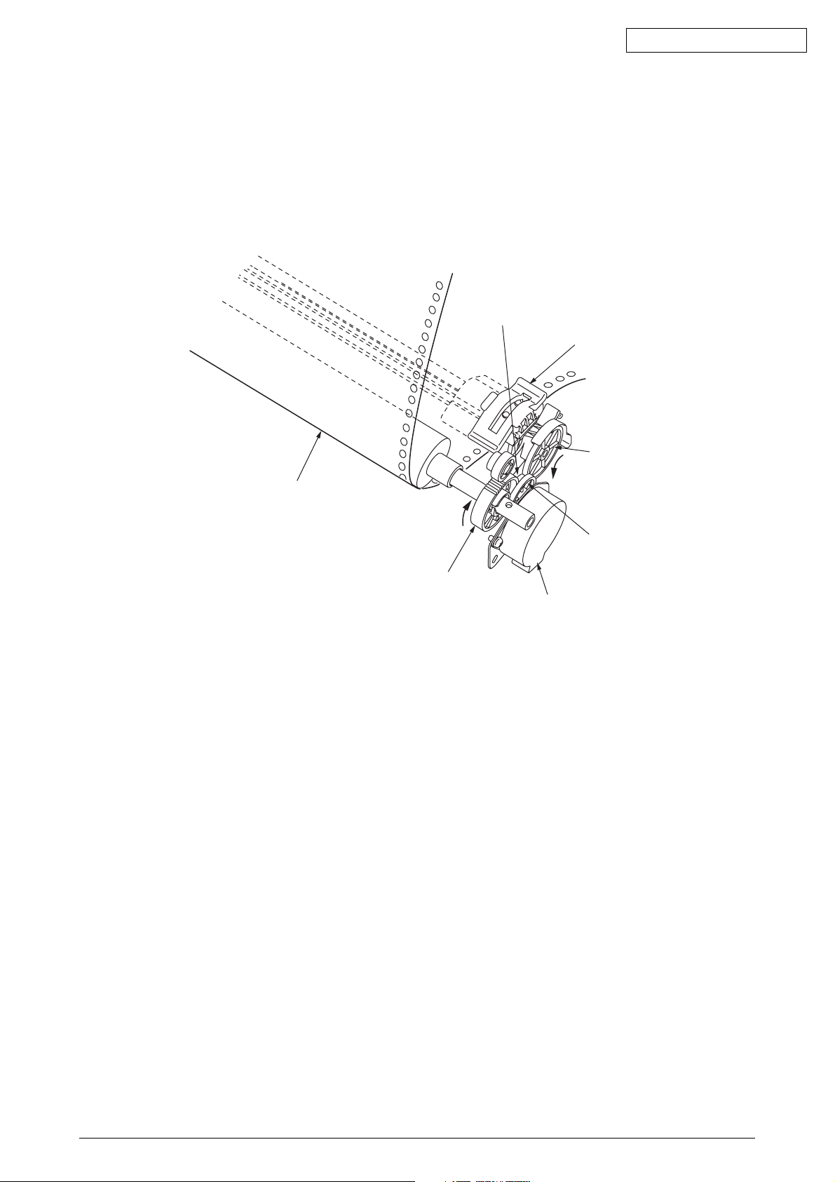
(3) Continuous paper feed operation (Rear) (See Figure 8.)
The force transmitted to the platen, rotates the tractor gear through platen gear, the idler
gear and the change gear. The rotation of the tractor gear makes the pin tractor belt rotate
through a sheet feeder shaft, feeding the continuous paper.
Change gear
Tractor
Paper
Tractor gear
Idle gear
Platen gear
LF motor
Figure 8
43471801TH Rev.1 20 /
Oki Data CONFIDENTIAL
(4) Bottom push feed operation (See Figure 9.)
Remove the pull-up assy.
By removing the tractor assy. installed in the rear and installing it above the platen, the
assy. is used for bottom pull feed.
The rotation of the LF motor is transmitted via the platen gear and the pull-up gear and
rotates the tractor gear.
The rotation of the tractor gear rotates the tractor shaft, which in turn feeds the continuous
form set in the tractor assy. into the print start position.
Platen
Platen gear
Figure 9
Tractor gear
pull gear
Idle gear
LF motor
43471801TH Rev.1 21 /
Oki Data CONFIDENTIAL
(5) Paper clamp mechanism (See Figure 10.)
When setting the change lever to the TOP or REAR , BOTTOM position, the operation
of the front release gear arm changes according to the position of the release cam. And
at the same time, the position of the cam installed to the front release gear shaft changes,
and the open and close of the pressure roller.
TOP
Position of
change lever
BOTTOM/REAR OPEN OPEN
TOP CLOSE CLOSE
Platen
Front roller
Open or close of
front pressure roller
Open or close of
rear pressure roller
Change lever
REAR/BOTTOM
Rerizu shaft
Figure 10
43471801TH Rev.1 22 /
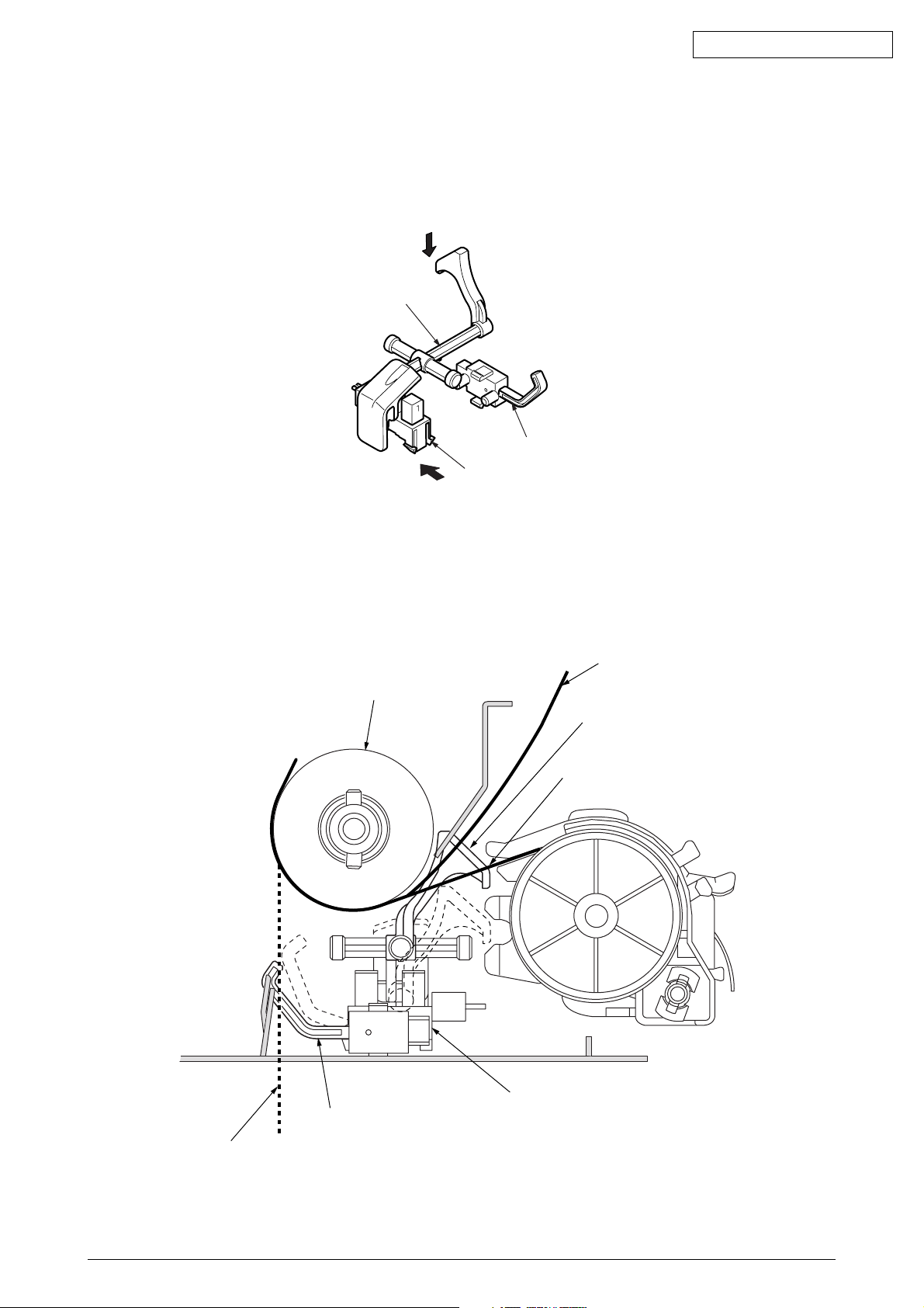
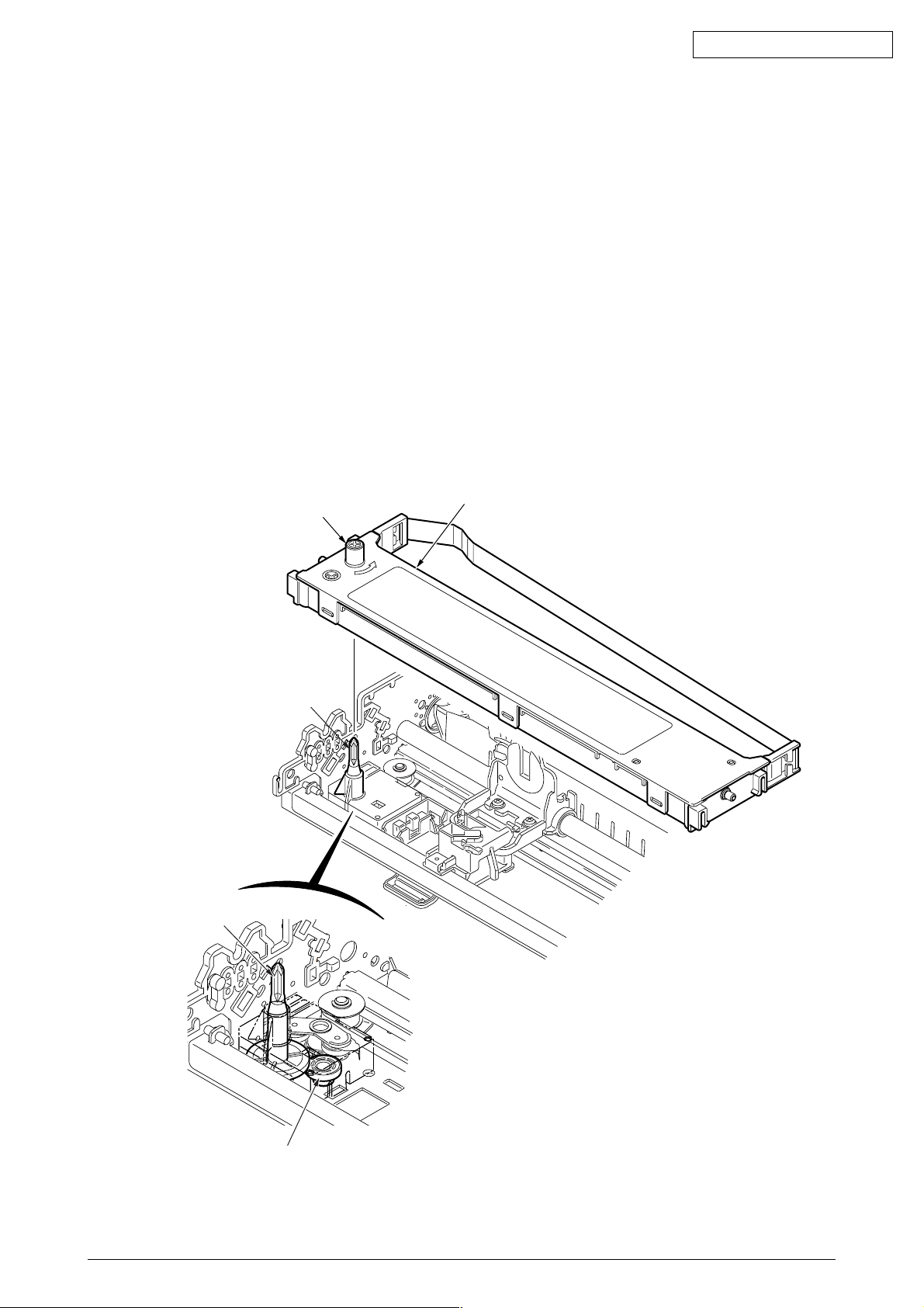
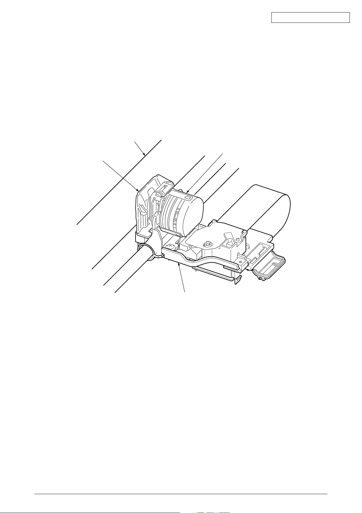
2.3.6 Paper Detection Mechanism
(1) Cut sheet detection/Rear feed detection(See Figure 11.)
When a cut sheet is inserted or a continuous form is fed by the tractor, the sensor arm
is pushed down by the paper and rotated. This moves the end of the sensor arm away
from the paper sensor that it has blocked, and the paper sensor detects “ON.”
Sensor arm
Oki Data CONFIDENTIAL
Bottom sensor
Paper end sensor
Figure 11
(2) Bottom feed detection(See Figure 12.)
When paper is fed from the bottom, the bottom sensor lever is pushed down by the paper
and the bottom sensor detects “ON.”
When the tail end of paper has passed the bottom sensor, the sensor lever returns into
position and the bottom sensor detects “OFF.”
Paper
Platen
(Cut shwwt feed)
Sensor arm
Paper
(Rear paper feed)
Peper end sensor
Bottom sensor lever
Paper
(bottom paper feed)
Figure 12
43471801TH Rev.1 23 /
Oki Data CONFIDENTIAL
(3) Top line print mechanism (See Figure 13.)
The front edge of the sheet is protected by the ribbon protector so that it can stop at a
position just near to the print head (0 tear off position) to start printing at the front end
of the sheet, without causing the sheet to crumple or curl up.
The printing starts at the front end of the sheet, and continues uni-directionally until the
front end of the sheet gets to the inside of the pull up roller cover.
After that, that printing continues bi-directionally.
Platen
Print head
Ribbon protector
Carriage frame assy
Figure 13
43471801TH Rev.1 24 /
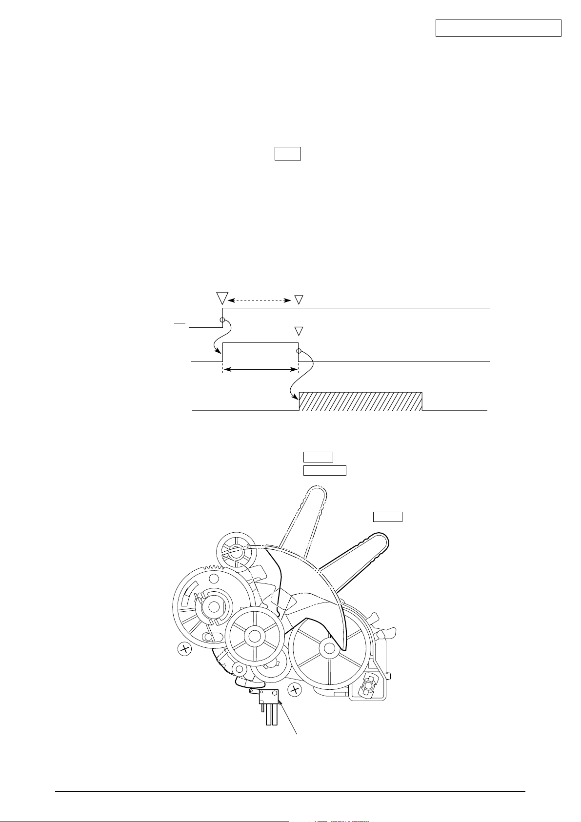
2.3.7 Automatic Sheet Feed (See Figure 14.)
This function is used to feed in the sheet automatically up to the print start position when the
cut sheet or the continuous sheet is used.
[Operational procedure]
(1) When using the cut sheet
1) Set the change lever to the TOP position. (See Figure 2-16.)
2) Insert a sheet of paper between the platen and the paper shoot.
3) After the lapse of time selected by the “wait time” in the menu, the LF motor starts
its operation to feed the sheet of paper up to the print position.
4) When the default is selected, the sheet of paper is feed in up to the position 0.85
inches (first dot position) from the upper end of the sheet. However, the 0 tear off
mechanism allows the printing at the front end of the sheet by changing the TOF
position.
Sheet setting
Oki Data CONFIDENTIAL
PE
Detection timer
LF action
Time out
Time selected
on the menu
REAR
BOTTOM
TOP
Top-Rear chang switch
Figure 14
43471801TH Rev.1 25 /
 Loading...