

Page 1
Page: 1
Service Guide OF1000
Chapter 0 About This Manual
OKIFAX 1000
Facsimile Product
Adobe Acrobat printable reference
copy of the OKIDATA Service Training Manual.
09/17/97
Note: This Adobe Acrobat version of the Okidata Service Training Manual was built with the
pictures rendered at 300 dpi, which is ideal for printing, but does not view on most
displays well.
Copyright 1997, Okidata, Division of OKI America, Inc. All rights reserved. See the OKIDATA Business
Partner Exchange (BPX) for any updates to this material. (http://bpx.okidata.com)
Page 2

Table of Contents Page
Service Guide OF1000
0 About This Manual
Front Cover 1
Manual Copyright 2
1 Product Specifications
1.1.01 General Information 3
1.2 General Facsimile Specifications 4
1.3 Communications 5
1.4 Printer Specifications 6
1.5 User Functions 7
1.6 Scanner Specifications 8
1.7 Consumable Items 9
1.8 Options 10
1.9 Agency Approvals 11
1.10 Reliability Data 12
2 Principles of Operation
2.1 Principles Of Operation 13
....2.1.01 Compatibility 14
....2.1.02 Communications Mode 15
....2.1.03 Modem Operation 16
....2.1.04 Automatic Fall-Back Mode 17
....2.1.05 Telephone Line Connection 18
....2.1.06 Error Correction Mode (ECM) 19
....2.1.07 Major Assemblies 20
........Okifax 1000 Cross-Sectional View 21
........Copy Function Block Diagram 22
........Report Print Function Block Diagram 23
2.2 Transmitter Theory Of Operation - Typical Transmission 24
....300 bps Transmit Handshake Operation Diagram 25
....300 bps Receive Handshake Procedure Diagram 26
....G3 Transmit Functional Block Diagram 27
....2.2.02 Operator Panel 28
....2.2.03 Automatic Document Feeder (ADF) 29
....2.2.04 Scanner Assembly 30
....2.2.05 Encoder 31
....2.2.06 Modem 32
....2.2.07 Network Control Board (NCU) 33
....2.2.08 Line Board 34
2.3 Receiver Theory Of Operation 35
....G3 Receive Operation Block Diagram 36
2.4 LED Printer - Principal Components 37
....2.4.02 Printer Control Board (PCNT-150) 38
....2.4.03 Power Supply Board (PWU-150) 39
Page 3

Table of Contents Page
........Power Supply Block Diagram 40
....2.4.04 Sub-Power Supply Board (PSUB-150) 41
........Sub-Power Supply Board Block Diagram 42
....2.4.05 Fuser Unit 43
....2.4.06 Main Motor (Drum Motor) 44
....2.4.07 LED Array 45
....2.4.08 DC Fan 46
....2.4.09 Registration Motor 47
2.5 Printing Process - General Information 48
........Printing Process Diagram 49
....2.5.02 Hopping 50
....2.5.03 Feeding 51
....2.5.04 Charging 52
....2.5.05 Exposing 53
....2.5.06 Developing 54
....2.5.07 Transfer 55
....2.5.08 Fusing 56
....2.5.09 Cleaning 57
....2.5.10 Printing 58
2.6 Sensors And Switches 59
....Sensor Location Diagram (Top View) 60
........Detail of Sensor / Lever 61
........Paper Inlet Jam 62
........Paper Feed Jam 63
....2.6.02 Toner Low Sensor 64
3 Maintenance & Disassembly
3.1 Maintenance - General Information 65
3.2 Disassembly/Assembly Procedures 66
....3.2.01 Preliminary Items 67
....3.2.02 LED Head 68
....3.2.03 Terminal Cover Cap, Rear Cover, and Fan 69
....3.2.04 Line Board (LINE-JU) 70
....3.2.05 Package Shelf Assembly 71
....3.2.06 Network Control Unit (NCU-U) 72
....3.2.07 Main Control Board (MCNT-150) 73
....3.2.08 Printer Control Board (PCNT-150) 74
....3.2.09 Left Side Cover 75
....3.2.10 Hook Switch Board (Hook-SW) 76
....3.2.11 Power Supply Unit (PWU) 77
....3.2.12 Gear Frame Assembly 78
....3.2.13 Transmit Stepper Motor 79
....3.2.14 Gear Frame and Gears 80
....3.2.15 Memory Card (Option) 81
....3.2.16 Right Side Cover 82
Page 4

Table of Contents Page
....3.2.17 Document Guide Assembly 83
....3.2.18 Speaker 84
....3.2.19 Separation Rubber Assembly 85
....3.2.20 Control Panel Assembly 86
....3.2.21 Upper Paper Guide Assembly 87
....3.2.22 Upper Feed Roller Assembly 88
....3.2.23 Pinch Roller 89
....3.2.24 Sub Pinch Roller Guide Assembly 90
....3.2.25 Paper Table Guide 91
....3.2.26 Sensor Roller Assembly 92
....3.2.27 Sub Roller Assembly 93
....3.2.28 ADF Roller Assembly 94
....3.2.29 Pinch Roller 95
....3.2.30 Document Detect Assembly (PC1) 96
....3.2.31 Read Station Sensor Assembly (PC2) 97
....3.2.32 Exit Guide 98
....3.2.33 Lower Feed Roller Assembly 99
....3.2.34 Image Sensor Assembly 100
....3.2.35 ADF Idle Gear 101
....3.2.36 Scanner Frame Assembly 102
....3.2.37 Release Guide Assembly 103
....3.2.38 Second Tray Interface Board 104
....3.2.39 Registration and Main Stepper Motors 105
....3.2.40 Eject Roller Assembly 106
....3.2.41 Manual Feed Guide Assembly 107
....3.2.42 Face-Down Stacker Cover Assembly 108
....3.2.43 Fuser Unit Assembly 109
....3.2.44 Lower Base Assembly 110
....3.2.45 Reduction and Stepper Motor Idle Gears 111
....3.2.46 Reset Levers and Pressure Roller 112
....3.2.47 Transfer Roller 113
....3.2.48 Registration Roller 114
....3.2.49 Hopping Roller Assembly 115
....3.2.50 Inlet Sensor Plates 116
....3.2.51 Outlet Sensor Plate 117
....3.2.52 Toner Sensor Plate 118
....3.2.53 Contact Assembly and Sub-Power Supply Board
(PSUB)
....3.2.54 Left and Right Cassette Guides and Base Assembly 120
....3.2.55 Paper Supply and Cassette Sensor Plates 121
3.3 Adjustments And Service Settings 122
........LED Intensity Rating / Dip Switch Settings Table 123
3.4 Cleaning 124
3.5 Lubrication 125
119
Page 5

Table of Contents Page
4 Failure & Repair Analysis
4.1 Failure & Repair Analysis - Introduction 126
4.2 Troubleshooting Updates 127
4.3 Reporting Problems 128
4.4 Troubleshooting Tips 129
4.5 Repair Analysis Procedures 130
....4.5.02 RAP Index 131
........RAP 01: No LCD Display 132
........RAP 02: Alarm LED is Lit 133
........RAP 03: Local Copy Problem 134
........RAP 04: Auto-Dial Problem 135
........RAP 05: Data Transmission Problem 136
........RAP 06: Auto Reception Problem 137
........RAP 07: Reception Problem 138
........RAP 08: Self-Diagnosis Failure 139
........RAP 09: Scan Operation Test Failure 140
........RAP 10: LED Test Failure 141
........RAP 11: Tone Test Failure 142
........RAP 12: High-Speed Modem Test Failure 143
........RAP 13: Multi-Frequency Tone Test Failure 144
........RAP 14: Printer Unit Print Test Failure 145
........RAP 15: Voice Message Test Failure 146
........RAP 16: No Acoustic Line Monitor 147
........RAP 17: Document Does Not Feed 148
........RAP 18: Multiple Documents Feed 149
........RAP 19: Document Skews 150
........RAP 20: Document Jams 151
........RAP 21: Printer Unit Problems Shown On LCD Display 152
............RAP 21A: Cover Open 153
............RAP 21B: Printer Alarm 1 154
............RAP 21C: Printer Alarm 2 155
............RAP 21D: Printer Alarm 3 156
............RAP 21E: Printer Alarm 4 157
............RAP 21F: Paper Jam - Confirm and Stop 158
............RAP 21G: No Paper 159
........RAP 22: Image Problems 160
............RAP 22A: Poor Print Quality (Images Light or Blurred
as a Whole)
............RAP 22B: Dark Background Density 162
............RAP 22C: Printed Output is Blank 163
............RAP 22D: Vertical Black Stripes on Printed Output 164
............RAP 22E: Repetitive Spaced Marks on Printed Output 165
............RAP 22F: Vertical White Streaks on Printed Output 166
............RAP 22G: Areas Missing From Printed Output 167
161
Page 6

Table of Contents Page
............RAP 22H: Poor Fusing 168
4.6 Local Diagnostic Testing 169
....4.6.01 Self-Diagnosis 170
....4.6.02 Scan Operation Test / CIS Calibration 171
....4.6.03 LED Test 172
....4.6.04 Tone Test 173
....4.6.05 High-Speed Modem Transmit Test 174
....4.6.06 High-Speed Modem Receive Test 175
....4.6.07 Multi-Frequency Tone Test 176
....4.6.08 Printer Unit Print Test 177
....4.6.09 Voice Message Test 178
4.7 Reports - Activity Report 179
....Service Codes List 180
....4.7.02 Protocol Dump 181
........Sample Analysis of Protocol Dump Data 182
........Facsimile Control Field Conversion Table 183
4.8 Resets 184
....4.8.01 Toner Counter Reset 185
....4.8.02 Drum Counter Reset 186
....4.8.03 Fuser Counter Reset 187
4.9 Clearing The Random Access Memory (RAM) 188
....4.10 Accessing the Technical Function Settings 189
........Technical Function (TF) Listing 190
....4.11 Telephone Answering Device (TAD) Interface 191
A Reference Charts
General Information 192
A.2 Index To Charts 193
....A.2.01 Main Control Board (MCNT-150) 194
....A.2.02 Printer Control Board (PCNT-150) 195
....A.2.03 Power Supply Board (PWU-150) 196
....A.2.04 Network Control Unit (NCU-U) 197
....A.2.05 Line Board (LINE-JU) 198
....A.2.06 Hook Switch (HOOK -150) 199
....A.2.07 Operator Panel Board (OPE-150) 200
....A.2.08 Sub-Power Supply Board (PSUB- 150) 201
....A.2.09 Second Tray Interface Board 202
B Illustrated Parts Listing
General Information & Parts Overview Diagram 203
....B.1.02 Definition of Terms 204
....B.1.03 Parts Ordering Information 205
B.2 CHARTS 206
....B.2.01 Cabinet Assembly (1 of 2) 207
....B.2.02 Cabinet Assembly (2 of 2) 208
....B.2.03 Control Panel Assembly 209
Page 7

Table of Contents Page
....B.2.04 Printer Assembly (1 of 3) 210
....B.2.05 Printer Assembly (2 of 3) 211
....B.2.06 Printer Assembly (3 of 3) 212
....B.2.07 Base Assembly (1 of 2) 213
....B.2.08 Base Assembly (2 of 2) 214
....B.2.09 Scan Assembly (1 of 2) 215
....B.2.10 Scan Assembly (2 of 2) 216
....B.2.11 Scan Unit (1 of 3) 217
....B.2.12 Scan Unit (2 of 3) 218
....B.2.13 Scan Unit (3 of 3) 219
....B.2.14 Upper Paper Guide Assembly (1 of 2) 220
....B.2.15 Upper Paper Guide Assembly (2 of 2) 221
....B.2.16 Cables (1 of 2) 222
....B.2.17 Cables (2 of 2) 223
....B.2.18 Options 224
....B.2.19 Packaging 225
....B.2.20 Consumables 226
....B.2.21 Documentation 227
Page 8

Service Guide OF1000
Chapter 0 About This Manual
This document may not be reproduced without written permission of the Okidata® Technical
Training Group. Every effort has been made to ensure the accuracy of the information contained
in this training course. Okidata is not responsible for errors beyond its control.
© 1994 by Okidata All rights reserved.
P/N 59261201 First Edition August, 1993
P/N 59261202 First Edition July, 1994
Written and produced by the Okidata Technical Training Group
Please address any comments on this publication to:
Okidata
Technical Training Group
Page: 2
532 Fellowship Road
Mount Laurel, NJ 08054-3499
Facsimile Number: (609) 235-2600, ext. 7034
Okilink Login Name: Technical Training
OKIDATA® is a registered trademark of Oki Electric Industry Company, Ltd.; marques deposee
de Oki Electric Industry Company, Ltd.; marca registrada, Oki Electric Industry Company, Ltd.
OKIFAX® is a registered trademark of Oki Electric Industry Company, Ltd.
Touch-Tone® is a registered trademark of American Telephone and Telegraph
Copyright 1997, Okidata, Division of OKI America, Inc. All rights reserved. See the OKIDATA Business
Partner Exchange (BPX) for any updates to this material. (http://bpx.okidata.com)
Page 9

Page: 3
Service Guide OF1000
Chapter 1 Product Specifications
1.1.01 General Information
The Okifax 1000 is a Group 3 facsimile unit which utilizes an LED page printer engine to produce a plain
paper, permanent copy of received data. The unit can store 85 auto dial locations and has 15 one touch
programmable keys. Scanning is accomplished by the direct contact image sensor method. The image
sensor consists of 1,728 elements. The Okifax 1000 has a scanning width of up to 8.5 inches.
Copyright 1997, Okidata, Division of OKI America, Inc. All rights reserved. See the OKIDATA Business
Partner Exchange (BPX) for any updates to this material. (http://bpx.okidata.com)
Page 10

1.2 GENERAL FACSIMILE SPECIFICATIONS
1.2.01 Style
· Desktop
1.2.02 Compatibility
· CCITT Group 3
1.2.03 Physical Dimensions
· Width
16.1 inches ( Approximately 410 mm)
· Depth
16.4 inches (Approximately 417 mm )
· Height
8.38 inches (Approximately 212.8 mm)
· Weight
26.5 pounds (Approximately 12 kg)
ONLY
Page: 4
Service Guide OF1000
Chapter 1 Product Specifications
1.2.04 Ambient Temperature and Relative Humidity (RH)
· Operation
50° to 90° F
10° to 30° C
20 to 80% RH
· Storage
-20° to 43° C
-4° to 109° F
Temperature Conversion Formulas
F° to C°:
C°= (F°-32) * .5556
C° to F°:
F°= (C°* 1.8) +32
1.2.05 Power Requirement
· 115 vac
1.2.06 Power Consumption
Mode
Transmit 40W
Receive 120W
Local Copy (All black) 118W (580W**)
Local Copy 125W
Standby 35W
Typical Power
Peak Power when the input voltage is 120V.
**
Page 11

1.2.07 LCD Display
· 2-line by 20 digit display
1.2.08 Memory
· Standard Memory
256 Kbytes (up to 14 pages of CCITT No.1 Sample Document)
· Optional Expansion Memory
1 Mbyte (up to 64 pages of CCITT No.1 Sample Document)
1.2.09 Copy Mode Resolution
· Fixed at 200 lines per inch
1.2.10 Warm-up Time
· From power On until printer is ready
Maximum of 120 seconds
1.2.11 Receive Options
· Auto Receive
· Manual Receive
· Tel/Fax Receive
· Telephone Answering Device (TAD) Mode
· No Paper Receive
· No Toner Receive
1.2.12 Transmit Document Specifications
· Document Width
Minimum 5.8 inches
Maximum 8.5 inches
· Document Length
Minimum 5 inches (single page), 5.8 inches (multi-page document)
Maximum 14 inches, or unlimited length for 1 hour
· Document Weight Range
16 pounds to 24 pounds
· Desired opacity
Less than 40 % of the scanner source light should be able to pass
through the paper.
1.2.13 Automatic Document Feeder (ADF) Capacity
· 30 sheets (20 pound bond)
Copyright 1997, Okidata, Division of OKI America, Inc. All rights reserved. See the OKIDATA Business
Partner Exchange (BPX) for any updates to this material. (http://bpx.okidata.com)
Page 12

1.3 COMMUNICATIONS
1.3.01 Telephone Line Compatibility
· PSTN (public switched telephone network)
· PBX (private branch exchange)
1.3.02 Communication Mode
· Half Duplex
1.3.03 Protocol
· CCITT Recommendation T.30
· Oki Special Protocol
In multi-document reception, the local unit can start transmitting
the modem training bits immediately after transmitting end of
message (EOM) and upon reception of message confirmation (MCF)
from the remote unit, instead of repeating all procedures (which takes
about six seconds).
· Oki Special High Speed
The T.30 handshake is conducted at message transmission speed
(instead of 300 bps) during multi-page transmission.
Page: 5
Service Guide OF1000
Chapter 1 Product Specifications
1.3.04 Line Interface
· Impedance
600 ohms balanced
· Send Power Level
0 dbm to -15 dbm (can be adjusted in 1 dbm steps by modifying TF #21)
1.3.05 Ring Signal Detection Sensitivity
· Voltage Range
25 to 150 r.m.s.
· Frequency Range
15 to 68 Hz (with 44 to 56 volts superimposed)
· Ring Signal Detection Time
One Ring Signal
or
Adjustable between 5 and 30 seconds, in 5 second increments
Refer to User Function 24 (optional second tray installed)
Refer to User Function 23 (optional second tray NOT installed)
· Ring Signal Voltage Duration
Longer than 180 milliseconds (inoperative if duration is
90 milliseconds or less)
1.3.06 Coding Schemes
· Modified Huffman (MH)
· Modified-Modified Read (MMR)
· Modified Huffman (MH)
Only
Page 13

1.3.07 Error Correction Methods
· CCITT Error Correction Mode (ECM)
· Page Re-transmission (Memory Mode / ECM Off)
1.3.08 High Speed Modem
· CCITT Recommendation V.29 (9600/7200 bps)
· CCITT Recommendation V.27 Ter. (4800/2400 bps)
1.3.09 Low Speed Modem
· CCITT Recommendation V.21 Channel 2 (300 bps)
1.3.10 Transmission Time
· 10 seconds
CCITT No. 1 sample document at 9600 bps
1.3.11 Transmit Resolution
· Horizontal
8 PELs per mm
(PEL = Picture ELement)
· Vertical
STD
3.85 lines per mm or 98 lines per inch
FINE
7.7 lines per mm or 196 lines per inch
Ex.FINE
15.4 lines per mm or 392 lines per inch
1.3.12 Photo/Half Tone Transmit Resolution
· 32 Levels (using error diffusion)
1.3.13 Ringer Equivalent Number
· 0.68
1.3.14 Transmit Dialing Methods
· Auto Dialing
70 two-digit auto dial codes
· One Touch Dialing
15 one-touch keys)
· Off Hook Dialing
· On Hook Dialing
· Broadcasting
Group Dial
1.3.15 Receive Mode
· Auto Receive
Dedicated fax machine
· Manual Receive
Telephone manual switch to fax mode
· Tel\Fax Auto Switching
Telephone will auto switch to fax mode
· TAD Interface
Page 14

1.3.16 Broadcast Transmit Capabilities
· Maximum: 85 locations in one session
1.3.17 TSI/CSI
· Maximum: 20 characters are displayed. If the function is enabled, the
received TSI is marked at the top of the first reproduced copy.
NOTE:
FEDERAL COMMUNICATIONS COMMISSION
TELEPHONE CONSUMER PROTECTION ACT
Part 68 Implementation of the Telephone Consumer Protection Act states:
" The Telephone Consumer Protection Act of 1991 makes it unlawful for any person to use a
computer or other electronic device to send any message via a telephone fax machine unless
such message clearly contains in a margin at the top or the bottom of each transmitted page, or
on the first page of the transmission, the date and time it is sent and an identification of the
business, other entity, or individual sending the message and the telephone number of the
sending machine of such business, other entity or individual."
To comply with this law, the End-User must:
1. Enter the DATE and TIME into the Okifax 1000
2. Enter the NAME and TELEPHONE NUMBER to identify the source
of their facsimile transmission.
Copyright 1997, Okidata, Division of OKI America, Inc. All rights reserved. See the OKIDATA Business
Partner Exchange (BPX) for any updates to this material. (http://bpx.okidata.com)
Page 15

1.4 PRINTER SPECIFICATIONS
1.4.01 Print Method
· Development
Dry electro-photography
· Exposure
Stationary LED head
1.4.02 Print Speed
· Continuous Print
4 sheets per minute (letter size)
· Warm-up Time
Power-ON (Cold): approximately 120 seconds
Idle: approximately 15 seconds
1.4.03 Receive Paper Sizes
· Letter
8.5 inches x 11.0 inches
Page: 6
Service Guide OF1000
Chapter 1 Product Specifications
· Legal (Option)
8.5 inches x 14.0 inches
1.4.04 Receive Paper Types
· 20 pound Bond Paper
1.4.05 Copy Stacking
· The Okifax 1000 stacks the printed output printed side down.
Face-down Stacker Capacity: 100 sheets
1.4.06 Paper Cassette Capacity
· First Cassette
100 sheets
· Second Cassette (Option)
250 sheets
1.4.07 One-Line Minimum Print Time
· Standard Resolution
10 milliseconds per line
· Fine Resolution
5 milliseconds per line
1.4.08 Contrast Selection
· Normal
· Light
· Dark
Page 16

Copyright 1997, Okidata, Division of OKI America, Inc. All rights reserved. See the OKIDATA Business
Partner Exchange (BPX) for any updates to this material. (http://bpx.okidata.com)
Page 17

1.5 USER FUNCTIONS
1.5.0l Transmit Mode
· Auto transmit mode
The Okifax 1000 begins sending messages after detecting
the remote stations answer.
· Manual transmit mode
The operator presses the Start Key after an answer tone has been
heard.
1.5.02 Receive Mode
· Auto Receive Mode
· Manual Receive Mode
· Telephone / Fax Automatic Switch
· TAD Interface
1.5.03 Absent Mode Auto Timer
· This feature enables switching to the auto receive mode at a specified time.
Page: 7
Service Guide OF1000
Chapter 1 Product Specifications
1.5.04 Group Dial
· One group of up to 85 locations
1.5.05 Telephone Directory and Location ID
· In addition to telephone numbers, an alphanumeric name can be assigned to
each of the numbers. This alphanumeric name is called the Location ID and can
contain up to 15 characters.
1.5.06 Voice Request
· A voice request from the transmitter is available only upon completion of the
total message transmission.
Copyright 1997, Okidata, Division of OKI America, Inc. All rights reserved. See the OKIDATA Business
Partner Exchange (BPX) for any updates to this material. (http://bpx.okidata.com)
Page 18

1.6 SCANNER SPECIFICATIONS
1.6.01 Scanning Method
· 1728 bit contact image sensor
1.6.02 Effective Reading Width
· Maximum: 8.5 inches
1.6.03 Scanning Resolution
· Horizontal
8 PELs per mm (PEL= Picture ELement) - approximately 200 PELs
per inch
· Vertical
3.85 lines per mm or 98 lines per inch (STD)
7.7 lines per mm or 196 lines per inch (FINE)
15.4 lines per mm or 392 lines per inch (Ex.FINE)
Page: 8
Service Guide OF1000
Chapter 1 Product Specifications
1.6.04 Automatic Document Feeder
· Maximum 30 sheets of 8.5 x 11 inch, 20 pounds bond paper
NOTE:
Documents must be placed face down on the ADF document guide.
Copyright 1997, Okidata, Division of OKI America, Inc. All rights reserved. See the OKIDATA Business
Partner Exchange (BPX) for any updates to this material. (http://bpx.okidata.com)
Page 19

Page: 9
Service Guide OF1000
Chapter 1 Product Specifications
1.7 CONSUMABLE ITEMS
1.7.01 Toner Cartridge Kit
· Toner Cartridge
· LED Lens Cleaner Pad
1.7.02 Image Drum Cartridge Kit
· Image drum
Copyright 1997, Okidata, Division of OKI America, Inc. All rights reserved. See the OKIDATA Business
Partner Exchange (BPX) for any updates to this material. (http://bpx.okidata.com)
Page 20

Page: 10
Service Guide OF1000
Chapter 1 Product Specifications
1.8 OPTIONS
1.8.01 Letter / Legal / Universal Paper Tray
· 100 sheet capacity
· Adjustable sizing capability (letter, legal, universal)
1.8.02 Second Tray Unit (ST-250)
· 250 sheet capacity
1.8.03 Memory Expansion Kit
· 1 MByte Memory Card
Copyright 1997, Okidata, Division of OKI America, Inc. All rights reserved. See the OKIDATA Business
Partner Exchange (BPX) for any updates to this material. (http://bpx.okidata.com)
Page 21

Page: 11
Service Guide OF1000
Chapter 1 Product Specifications
1.9 AGENCY APPROVALS
· FCC Class A
· UL 478 Ver. 5
· CSA 22.2 220
Copyright 1997, Okidata, Division of OKI America, Inc. All rights reserved. See the OKIDATA Business
Partner Exchange (BPX) for any updates to this material. (http://bpx.okidata.com)
Page 22

1.10 RELIABILITY DATA
1.10.01 Automatic Document Feeder Jam Rate
· Approximately one for every 500 operations
1.10.02 Separation Rubber Life
· Approximately 10,000 document feeds
1.10.03 Lithium Battery Life
· Approximately 5 years
1.10.04 Image Drum Life
· One page print jobs
Up to 11,000 pages
· Continuous print
Up to 20,000 pages
Page: 12
Service Guide OF1000
Chapter 1 Product Specifications
1.10.05 Toner Cartridge Life
· First toner cartridge in image drum
Up to 1,250 pages
· Subsequent toner cartridges
Up to 2,500 pages
1.10.06 Estimated Fuser Life
· Approximately 180,000 pages
1.10.07 Facsimile Mean Time Between Failure (MTBF)
· Approximately 3,000 hours
1.10.08 Printer Duty Cycle
· Approximately 6,000 pages per month
1.10.09 Estimated Printer Life
· Approximately 180,000 pages
1.10.10 Mean Time To Repair (MTTR)
· Approximately 30 minutes
Copyright 1997, Okidata, Division of OKI America, Inc. All rights reserved. See the OKIDATA Business
Partner Exchange (BPX) for any updates to this material. (http://bpx.okidata.com)
Page 23

Page: 13
Service Guide OF1000
Chapter 2 Principles of Operation
2.1 PRINCIPLES OF OPERATION
The Okifax 1000 Principles of Operation section is comprised of three sub-sections.
· Transmitter Theory of Operation
· Receiver Theory of Operation
· LED Printer Theory of Operation
Copyright 1997, Okidata, Division of OKI America, Inc. All rights reserved. See the OKIDATA Business
Partner Exchange (BPX) for any updates to this material. (http://bpx.okidata.com)
Page 24

Page: 14
Service Guide OF1000
Chapter 2 Principles of Operation
2.1.01 Compatibility
The Okifax 1000 facsimile machine operates as a Group 3 (G3) facsimile device.
Copyright 1997, Okidata, Division of OKI America, Inc. All rights reserved. See the OKIDATA Business
Partner Exchange (BPX) for any updates to this material. (http://bpx.okidata.com)
Page 25

Page: 15
Service Guide OF1000
Chapter 2 Principles of Operation
2.1.02 Communications Mode
The Okifax 1000 operates as a half-duplex facsimile transceiver. Transmit and receive operations
cannot take place at the same time. However, documents can be prepared for transmission while
the Okifax 1000 is engaged in message reception. These documents will be automatically
transmitted upon completion of the receiving operation.
Copyright 1997, Okidata, Division of OKI America, Inc. All rights reserved. See the OKIDATA Business
Partner Exchange (BPX) for any updates to this material. (http://bpx.okidata.com)
Page 26

Page: 16
Service Guide OF1000
Chapter 2 Principles of Operation
2.1.03 Modem Operation
The high-speed modem conforms to CCITT Standard V.29 for 9600/7200 bps (bits per second)
operation and to CCITT Standard V.27 ter. for 4800/2400 bps operation.
The low-speed (300 bps) modem, which is used for handshaking, conforms to CCITT standard
V.21 channel 2 or equivalent.
Copyright 1997, Okidata, Division of OKI America, Inc. All rights reserved. See the OKIDATA Business
Partner Exchange (BPX) for any updates to this material. (http://bpx.okidata.com)
Page 27

Page: 17
Service Guide OF1000
Chapter 2 Principles of Operation
2.1.04 Automatic Fall-back Mode
The Okifax 1000 will change the message transmitting speed according to the following fall-back
plan. The Okifax 1000 will first transmit a page of the message at 9600 bps. The receiving station
will continuously monitor the received data. If the receiving station detects six or more consecutive
error lines during reception of a single page, or if the total number of errors detected during the
reception of a single page exceeds 10% of the data on the transmitted page, it will return an RTN
(Retrain Negative) signal to the transmitting station upon termination of the page reception. With
an RTN signal received, the transmitting station will downgrade its speed by one level (to 7200
bps in this case) and continue transmission of the next page. Similarly, should the transmitting
station again receive an RTN signal from the receiving station, it will downgrade speed another
level.
Copyright 1997, Okidata, Division of OKI America, Inc. All rights reserved. See the OKIDATA Business
Partner Exchange (BPX) for any updates to this material. (http://bpx.okidata.com)
Page 28

Page: 18
Service Guide OF1000
Chapter 2 Principles of Operation
2.1.05 Telephone Line Connection
The Okifax 1000 is connected to the telephone line via the LINE-JU Board. Two RJ-11 connectors
are provided; one for connection to the phone line, and the other for an external telephone. A
separate modular jack is provided for connection of the Okifax 1000s handset.
The Okifax 1000 will control the switching between the handset (or the external telephone) and
the telephone line to permit use of the handset or telephone for voice communication.
Copyright 1997, Okidata, Division of OKI America, Inc. All rights reserved. See the OKIDATA Business
Partner Exchange (BPX) for any updates to this material. (http://bpx.okidata.com)
Page 29

Service Guide OF1000
Chapter 2 Principles of Operation
2.1.06 Error Correction Mode (ECM)
The Okifax 1000 features Error Correction Mode (ECM). When communicating with a remote unit
that also has ECM, this feature provides error-free transmission.
What follows is an explanation of how ECM works.
· The transmit machine groups image data into blocks and transmits one block
of data at a time to the receive machine. At the end of each block, a PPS (Partial Page
Signal) is transmitted.
· The receive machine stores the data block in memory and checks each frame within that block
for errors.
- Modified Huffman assigns a binary code to consecutive recurring bits of white or black.
The codes must add up to a total of 1728 bits, which is the Main Scan Rate established
by CCITT.
Page: 19
- Modified Read uses a comparison technique. The line being coded is compared to
the previous line and differences are noted. Codes are then assigned to reflect the
differences between the two lines.
· If no errors are detected, the receiver sends MCF (Message Confirmation) which requests the
transmit machine to transmit the next data block.
· If an error is detected by the receive machine, it transmits the frame number of the defective
frame back to the transmit machine in a signal called PPR (Partial Page Request).
· The transmit machine will then re-transmit the frame to the receive machine as a Partial Page.
· The receive machine rechecks the Partial Page, and (if all frames are correct) the receive
machine transmits MCF (Message Confirmation).
· The next data block is then transmitted.
Copyright 1997, Okidata, Division of OKI America, Inc. All rights reserved. See the OKIDATA Business
Partner Exchange (BPX) for any updates to this material. (http://bpx.okidata.com)
Page 30

Service Guide OF1000
Chapter 2 Principles of Operation
2.1.07 Major Assemblies
The following major assemblies make up the Okifax 1000 facsimile machine.
· Main Control Board MCNT-150
· Printer Interface Board PCNT-150
· Network Control Unit Board NCU-U
· Operation Panel Assembly OPE-150
· Power Supply Board (FXLA) PWU-150
· Sub-Power Supply Board (FXHA) PSUB-150
· Line Board LINE-JU
Page: 20
· Hook Switch Board HOOK SW
· Printer Unit
· Scan Unit
Copyright 1997, Okidata, Division of OKI America, Inc. All rights reserved. See the OKIDATA Business
Partner Exchange (BPX) for any updates to this material. (http://bpx.okidata.com)
Page 31
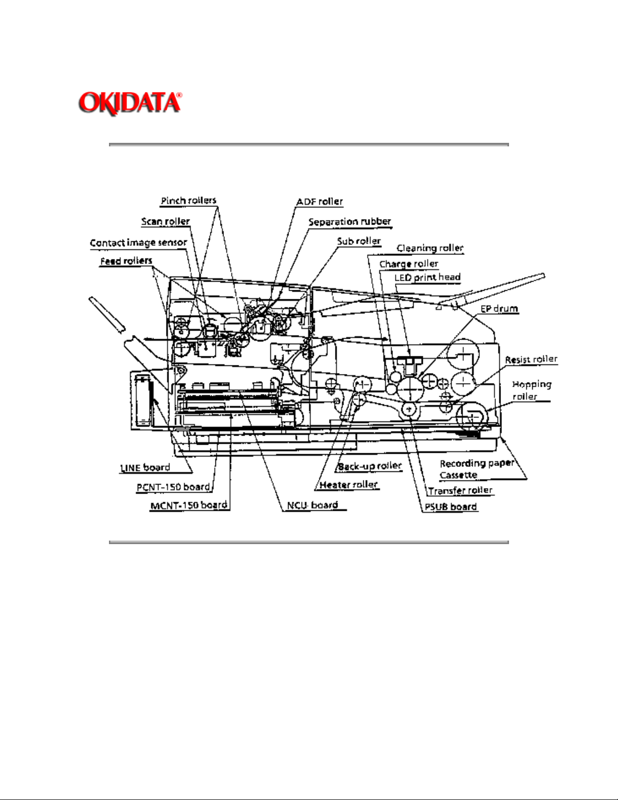
Okifax 1000 Cross-Sectional View
Page: 21
Service Guide OF1000
Chapter 2 Principles of Operation
Copyright 1997, Okidata, Division of OKI America, Inc. All rights reserved. See the OKIDATA Business
Partner Exchange (BPX) for any updates to this material. (http://bpx.okidata.com)
Page 32
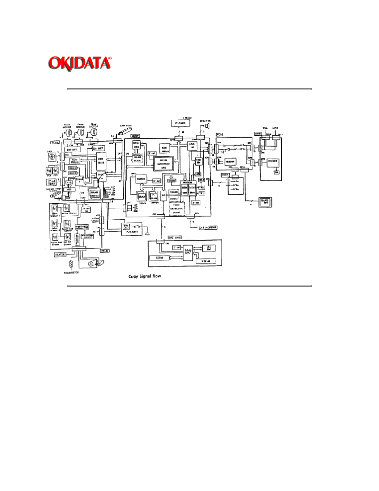
Copy Function Block Diagram
Page: 22
Service Guide OF1000
Chapter 2 Principles of Operation
Copyright 1997, Okidata, Division of OKI America, Inc. All rights reserved. See the OKIDATA Business
Partner Exchange (BPX) for any updates to this material. (http://bpx.okidata.com)
Page 33
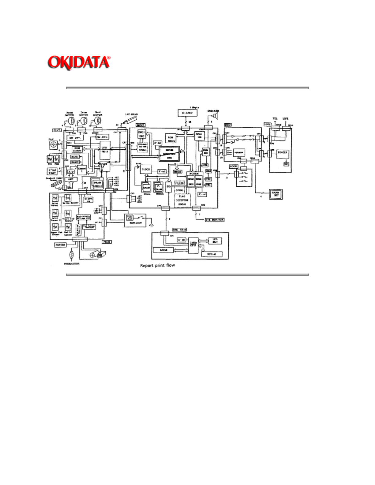
Report Print Function Block Diagram
Page: 23
Service Guide OF1000
Chapter 2 Principles of Operation
Copyright 1997, Okidata, Division of OKI America, Inc. All rights reserved. See the OKIDATA Business
Partner Exchange (BPX) for any updates to this material. (http://bpx.okidata.com)
Page 34

Page: 24
Service Guide OF1000
Chapter 2 Principles of Operation
2.2 TRANSMITTER THEORY OF OPERATION
2.2.01 Typical Transmission
When a telephone number is dialed through the Okifax 1000 (either manually or through auto-dial), a
connection will be established with the receiving station through the Public Switched Telephone Network
(PSTN). When the call is answered, the operator will hear the Called Equipment Device (CED) tone from
the receiving station. With CED received, the transmit machine acknowledges that the connection is
established and proceeds to the CCITT T.30 300 bps handshake procedure.
NOTE:
Refer to the Receive
overviews of 300 bps handshaking.
Refer to the Transmit Block Diagram for an overview of G3 Transmit Operations.
When the DIS (Digital Identification Signal) is received, G3 mode transmission is possible and the Okifax
1000 starts scanning the document, page by page. The image data is temporarily stored in FIFO (First In
First Out) memory until it becomes valid for transmission. In about 3 seconds, the machine will receive
CSI (Called Subscriber Identification) from the distant station. After reading the document pages and
storing the image data in memory, the machine begins the handshake with the distant station. If the 9600
bps training is successfully completed, the machine will start transmitting the image data in digital, coded
form. Training is a high speed data pattern transmitted to the receive modem. This training data pattern
causes the receive modem to synchronize with the transmit modem. If the training fails due to the line
condition, an automatic fallback to a lower rate will occur. The result will be indicated on the LCD display.
As the machine transmits each page of image data, the page count on the LCD display will increment.
and Transmit Handshake Procedure Block Diagrams for functional
Training is used :
· To test the line condition for valid transmissions at a particular data rate.
The TCF consists of 100 binary 0s transmitted in a burst. At least 98% accuracy
must be achieved before transmission can take place at that data rate.
· By the receiving station in setting preliminary equalization for the current line conditions.
Copyright 1997, Okidata, Division of OKI America, Inc. All rights reserved. See the OKIDATA Business
Partner Exchange (BPX) for any updates to this material. (http://bpx.okidata.com)
Page 35
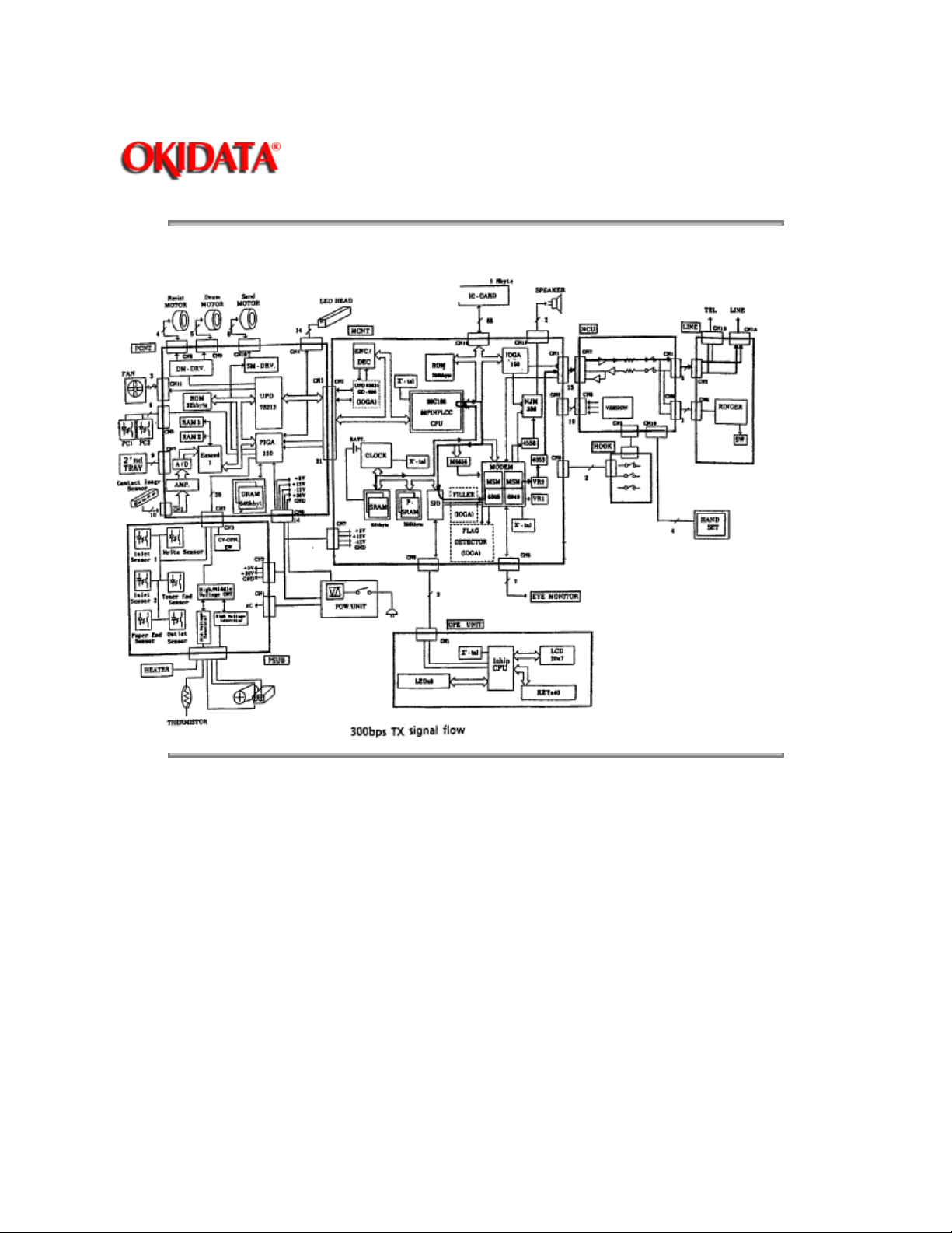
300 bps Transmit Handshake Operation Diagram
Page: 25
Service Guide OF1000
Chapter 2 Principles of Operation
Copyright 1997, Okidata, Division of OKI America, Inc. All rights reserved. See the OKIDATA Business
Partner Exchange (BPX) for any updates to this material. (http://bpx.okidata.com)
Page 36
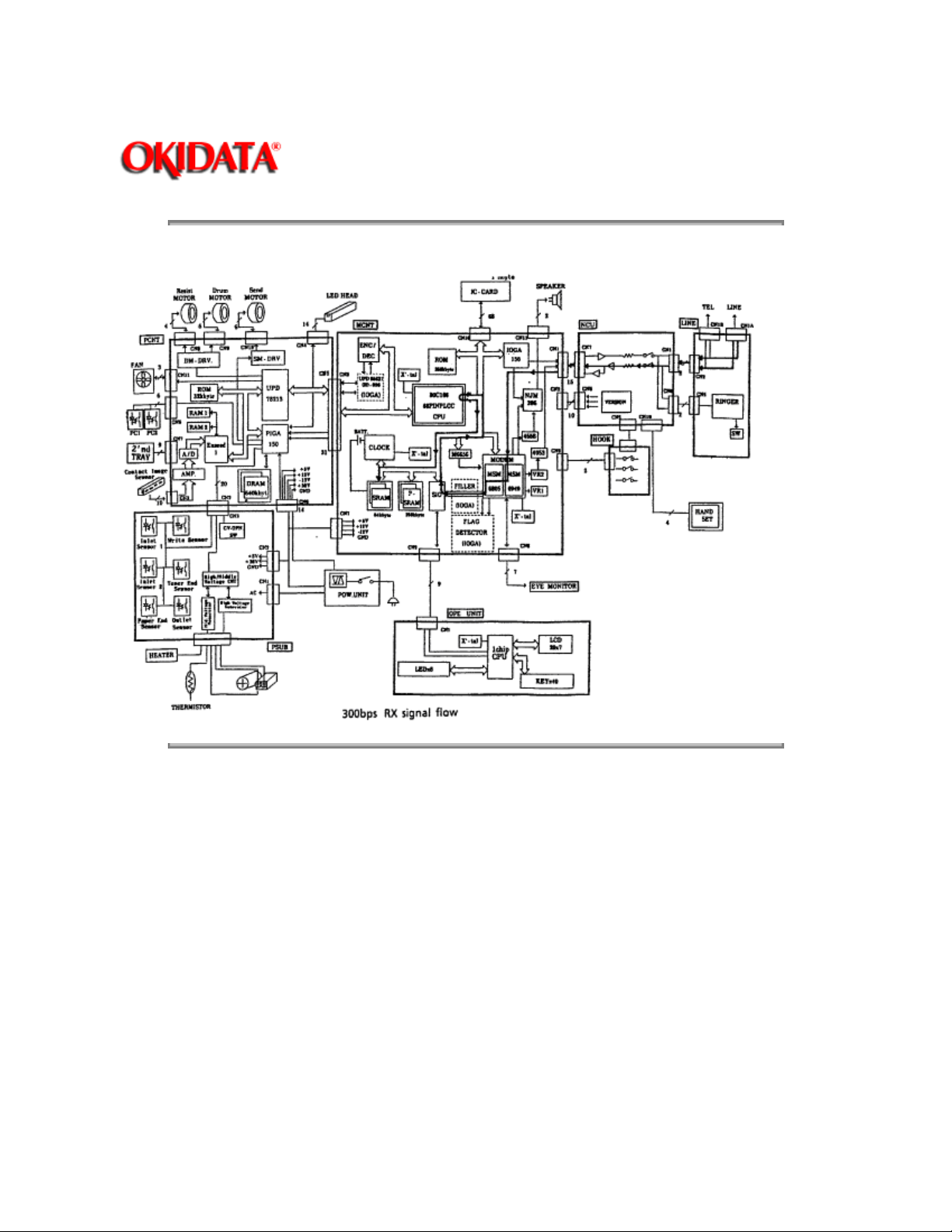
300 bps Receive Handshake Procedure Diagram
Page: 26
Service Guide OF1000
Chapter 2 Principles of Operation
Copyright 1997, Okidata, Division of OKI America, Inc. All rights reserved. See the OKIDATA Business
Partner Exchange (BPX) for any updates to this material. (http://bpx.okidata.com)
Page 37
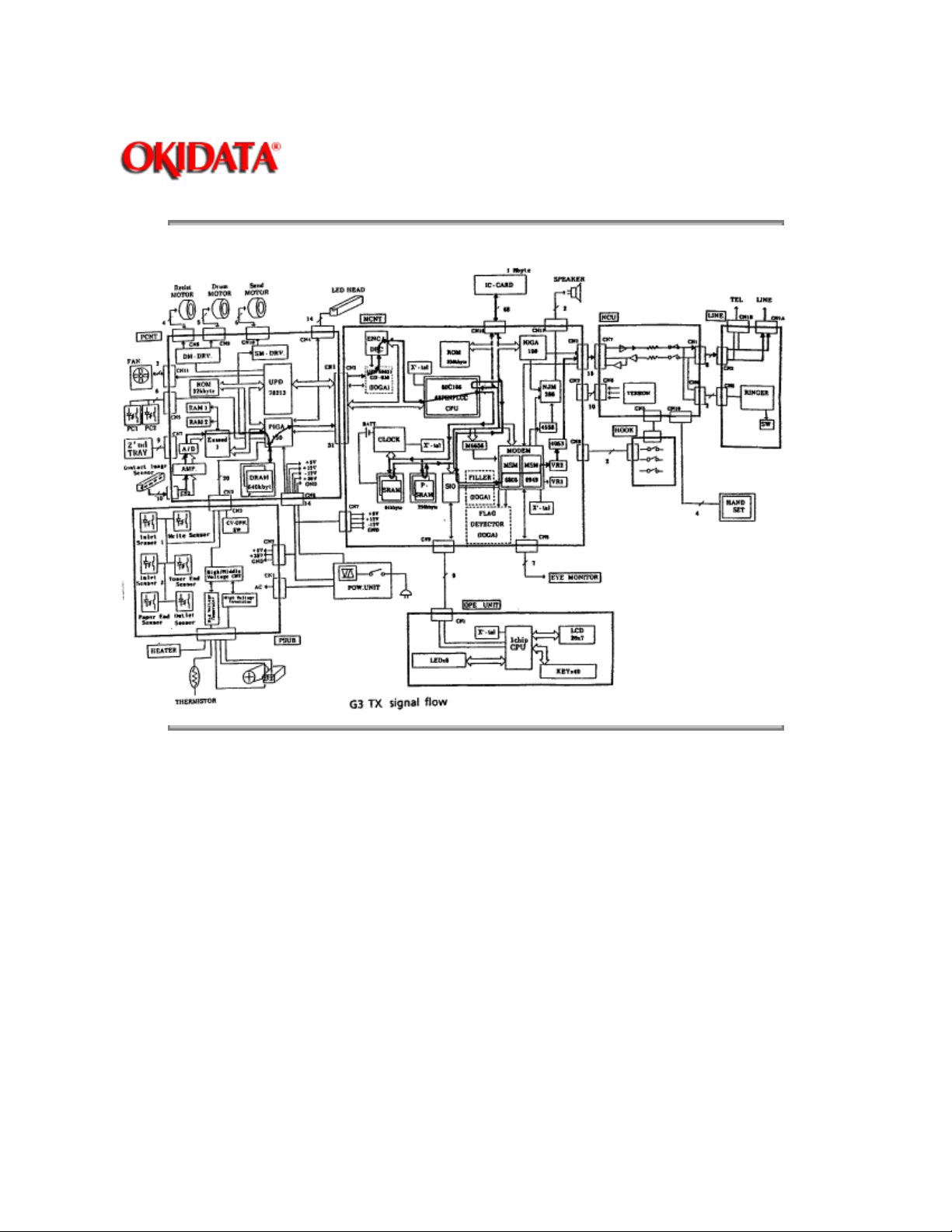
G3 Transmit Functional Block Diagram
Page: 27
Service Guide OF1000
Chapter 2 Principles of Operation
Copyright 1997, Okidata, Division of OKI America, Inc. All rights reserved. See the OKIDATA Business
Partner Exchange (BPX) for any updates to this material. (http://bpx.okidata.com)
Page 38

Page: 28
Service Guide OF1000
Chapter 2 Principles of Operation
2.2.02 Operator Panel
Through the operator panel (OPE-150), the end user initiates transmit and receive operations,
sets desired options, programs telephone numbers and other data, and interfaces in all facets of
the operation of the machine. The panel consists of an LCD display (two rows of 20 characters), a
numeric key pad, 8 LED indicators, and function keys. The functions of the keys and indicators
are described in the Okifax 1000 Users Documentation.
Copyright 1997, Okidata, Division of OKI America, Inc. All rights reserved. See the OKIDATA Business
Partner Exchange (BPX) for any updates to this material. (http://bpx.okidata.com)
Page 39
Service Guide OF1000
Chapter 2 Principles of Operation
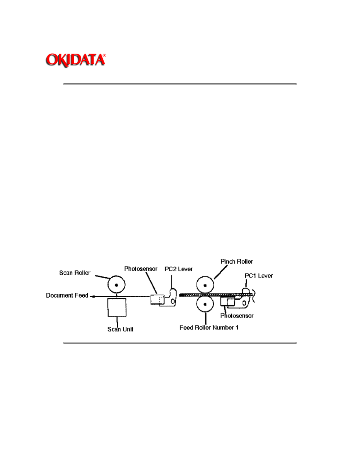
2.2.03 Automatic Document Feeder (ADF)
The automatic document feeder transfers document sheets to the scan unit automatically, one at
a time. The following diagram shows the mechanism used for detecting the leading and trailing
edges of a document.
When a document is placed on the feeder, it is sensed by PC1. This causes the feed rollers to
activate, feeding the document. The document is fed to the PC2 lever, where the leading edge of
the document is detected. When transmit (or copy) begins, the document is fed by the transmit
stepper motor to the start scan position where reading start. The documents trailing edge is
detected when the PC2 lever is released. If another document is on the feeder, the process is
repeated.
The separation rubber holds back the top originals and allows only one document to be fed into
the scanner area. The separation rubber and ADF rollers should be cleaned or replaced according
to the cleaning schedule (in Section 3 of this manual) to assure proper operation.
The ADF capacity is 30 pages of 20 lb. bond. Documents are placed on the feeder image face
side down. When feeding multiple pages, the bottom page is fed first, working toward the top.
Page: 29
Document Leading/Trailing Edge Detection Diagram
Copyright 1997, Okidata, Division of OKI America, Inc. All rights reserved. See the OKIDATA Business
Partner Exchange (BPX) for any updates to this material. (http://bpx.okidata.com)
Page 40

Service Guide OF1000
Chapter 2 Principles of Operation
2.2.04 Scanner Assembly
The Okifax 1000 uses a 1728-element direct contact type image scanning sensor. LEDs are
located at the bottom of the scan glass and image sensors are located at the top of the glass.
When the document reaches the scanning unit, it passes directly in front of the image sensor. The
LEDs illuminate the document and the light reflects back to the image sensors. This image data is
sent to the printer control board (PCNT-150). The transmitted document length is limited to 14
inches; however, the machine can be modified for longer transmissions. (See Transmitting Long
Documents
Transmission will stop and a line disconnect will occur if the end of the document is not detected
within 14 inches after scanning begins (unless the unit is set for unlimited transmission.) The
message
in the Users Documentation).
RE-LOAD DOCUMENT
CONFIRM AND "STOP"
Page: 30
will be displayed if the document does not reach the scanning position within 5 seconds after the
start of a document feed.
NOTE:
When a jam condition is displayed on the operator panel during message transmission, the
machine will stop
Copyright 1997, Okidata, Division of OKI America, Inc. All rights reserved. See the OKIDATA Business
Partner Exchange (BPX) for any updates to this material. (http://bpx.okidata.com)
, but its receiving capability will remain active.
Page 41

Page: 31
Service Guide OF1000
Chapter 2 Principles of Operation
2.2.05 Encoder
Scanned image data received by the PCNT is sent to the encoder/decoder (ENC/DEC) on the
MCNT-150 board. The image data is compressed by the ENC/DEC according to the Modified
Huffman (MH) and Modified Read (MR) encoding scheme, or MH only. The use of MH only or
both MH and MR is determined by a function setting. Data is then stored in the FIFO area in one
byte units. Fill bits are inserted if the length of one encoded line is less than the minimum scan
time of the remote unit. Data is transferred to the NCU board, then sent to the line board for
transmission over the phone line.
Copyright 1997, Okidata, Division of OKI America, Inc. All rights reserved. See the OKIDATA Business
Partner Exchange (BPX) for any updates to this material. (http://bpx.okidata.com)
Page 42

Page: 32
Service Guide OF1000
Chapter 2 Principles of Operation
2.2.06 Modem
The modem, located on the MCNT-150 board, modulates the data in the correct G3 (9.6, 7.2, 4.8,
or 2.4K bps) data rate that was determined during handshaking between the local machine and
the remote receiver. Modulation is the process of converting the digital output of the scanner into
an analog signal that can be transmitted over the telephone system.
Copyright 1997, Okidata, Division of OKI America, Inc. All rights reserved. See the OKIDATA Business
Partner Exchange (BPX) for any updates to this material. (http://bpx.okidata.com)
Page 43

Service Guide OF1000
Chapter 2 Principles of Operation
2.2.07 Network Control Board (NCU)
The NCU-U board receives the modulated data from the MCNT-150 board and transfers the data
to the line board.
The NCU board performs the following functions during the transmit operation.
· Unit connection / disconnection to the telephone line via the CML Relay
· Dial pulse generation
· The PIS Tone detection
· Off-Hook Detection (Line Current Detector)
· Tx Output Signal Attenuation (normally 9 db output)
Page: 33
· Separation of the TX and RX signals (performed by the Hybrid Transformer)
· Impedance matching (the 600 ohm impedance of the telephone line)
Copyright 1997, Okidata, Division of OKI America, Inc. All rights reserved. See the OKIDATA Business
Partner Exchange (BPX) for any updates to this material. (http://bpx.okidata.com)
Page 44

Page: 34
Service Guide OF1000
Chapter 2 Principles of Operation
2.2.08 Line Board
The line board provides the RJ-11 connection used to transmit data to the PSTN or PBX.
Copyright 1997, Okidata, Division of OKI America, Inc. All rights reserved. See the OKIDATA Business
Partner Exchange (BPX) for any updates to this material. (http://bpx.okidata.com)
Page 45

Service Guide OF1000
Chapter 2 Principles of Operation
2.3 RECEIVER THEORY OF OPERATION
NOTE:
Refer to the G3 Receive Operation Block Diagram
2.3.01 Operator Panel
Through the operator panel, the user initiates manual receive operations and sets auto-answer
options.
2.3.02 Line Board
The line board provides the RJ-11 connection used to receive data from the PSTN or PBX.
2.3.03 Network Control Board (NCU)
The NCU receives the modulated data from the line board and sends it to the modem (located on
the MCNT board). The operation of the NCU in the receive mode is very similar to the transmit
mode. However, during receive operations, the NCU also functions as an amplifier for the
received signal.
.
Page: 35
2.3.04 Modem
The modem demodulates the data from the G3 (9.6, 7.2, 4.8, or 2.4K bps) scheme that was
determined during handshaking. The data is then sent to the read-only memory for temporary
storage. The storage time is dependent on whether the machine is printing real-time or from
memory.
2.3.05 Decoder
The decoder decodes the MH, MR, or MMR data from the RAM into lines of picture data that are
1,728 bits in length. After the data has been received, demodulated, and decoded, it is transferred
to the PCNT board.
2.3.06 Document Size
Since the available printing area of the printer is smaller than the paper size, document contents
may be missed on both sides of the paper, or a document image having the same length as the
printing paper may be split into separate pages during printing. To prevent this, the Okifax 1000
automatically sets the proper reduction ratio within the range of 90 to 100% if the RX
REDUCTION function has been set ON. If a received document image is longer than the available
printing length, the excess part of the image is eliminated. If the SPLIT PRINT function has been
set ON, the excess image will be printed on the next page.
Copyright 1997, Okidata, Division of OKI America, Inc. All rights reserved. See the OKIDATA Business
Partner Exchange (BPX) for any updates to this material. (http://bpx.okidata.com)
Page 46
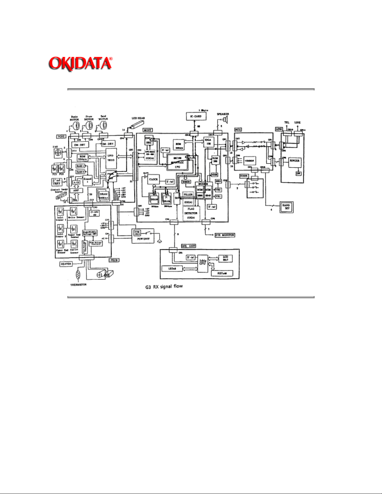
G3 Receive Operation Block Diagram
Page: 36
Service Guide OF1000
Chapter 2 Principles of Operation
Copyright 1997, Okidata, Division of OKI America, Inc. All rights reserved. See the OKIDATA Business
Partner Exchange (BPX) for any updates to this material. (http://bpx.okidata.com)
Page 47

Service Guide OF1000
Chapter 2 Principles of Operation
2.4 LED PRINTER
2.4.01 Principal Components
The principal hardware components of the printer unit are listed below.
· Printer Control Board (PCNT-150)
· Power Supply Board (PWU-150)
· Sub-Power Board (PSUB-150)
· Fuser Unit
· Main Motor
· LED Head
Page: 37
· Registration Motor
· DC Fan
· Second Paper Tray Mechanism (option)
Copyright 1997, Okidata, Division of OKI America, Inc. All rights reserved. See the OKIDATA Business
Partner Exchange (BPX) for any updates to this material. (http://bpx.okidata.com)
Page 48

Page: 38
Service Guide OF1000
Chapter 2 Principles of Operation
2.4.02 Printer Control Board (PCNT-150)
The printer control board (PCNT-150) contains a microprocessor, an EPROM which stores the
printer control program, and 640 Kbytes of dynamic RAM.
This board controls the paper feed and paper transport functions. This board also activates the
LED array diodes, which leave a latent electrostatic image on the photosensitive drum. This latent
image is printed by fusing toner to the paper.
Copyright 1997, Okidata, Division of OKI America, Inc. All rights reserved. See the OKIDATA Business
Partner Exchange (BPX) for any updates to this material. (http://bpx.okidata.com)
Page 49

Page: 39
Service Guide OF1000
Chapter 2 Principles of Operation
2.4.03 Power Supply Board (PWU-150)
The power supply is a switching-type unit, which generates the following voltages from the AC
input voltage.
· + 5 vdc : Printer Logic
· + / - 12 vdc: Interface Signal Levels
· + 38 vdc: Transmit Stepper Motor, Registration / Drum Motor Drive,
Fan Drive, high-voltage source.
When the PCNT-150 board enables the HEATON signal, the power supply provides the AC
voltage to the fuser lamp via the PSUB-150 board.
Copyright 1997, Okidata, Division of OKI America, Inc. All rights reserved. See the OKIDATA Business
Partner Exchange (BPX) for any updates to this material. (http://bpx.okidata.com)
Page 50
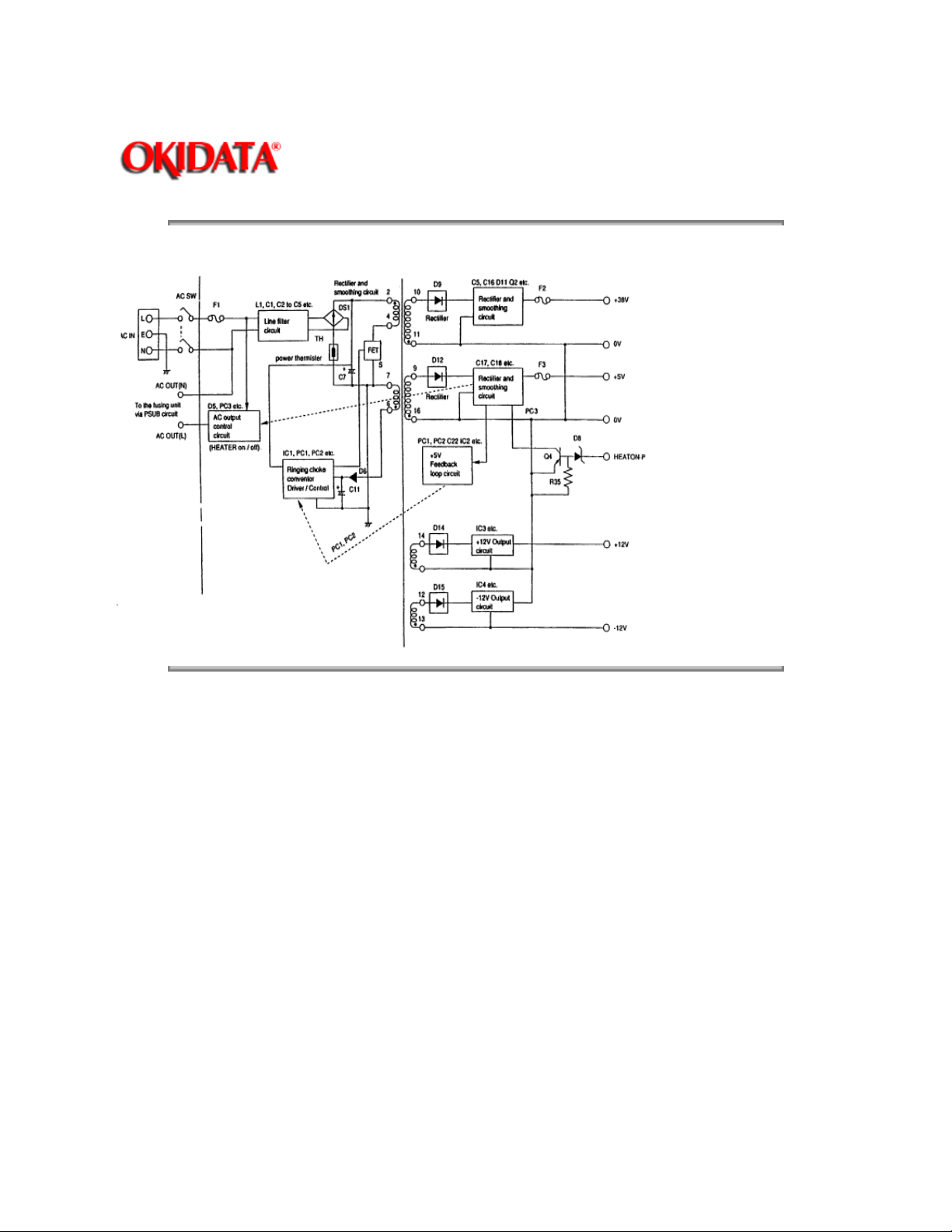
Power Supply Block Diagram
Page: 40
Service Guide OF1000
Chapter 2 Principles of Operation
Copyright 1997, Okidata, Division of OKI America, Inc. All rights reserved. See the OKIDATA Business
Partner Exchange (BPX) for any updates to this material. (http://bpx.okidata.com)
Page 51
Page: 41
Service Guide OF1000
Chapter 2 Principles of Operation
2.4.04 Sub-Power Supply Board (PSUB-150)
The PSUB-150 consists of IC1 (a one-chip CPU), a cover-open switch, the high voltage generation circuit
and the photo-sensors.
Photosensors
· PS1 - Outlet Sensor
- Detects paper jams at the paper exit path.
· PS2 - Paper Sensor
- Along with the outlet sensor, is used to monitor paper feed and paper length.
· PS3 - Inlet Sensor 1
- Detects the leading edge of the paper. Used in the determination of when to
switch from the hopping to feeding operation.
· PS4 - Paper-end Sensor
- Detects the presence of paper in the cassette. (ON: Paper is present)
· PS5 - Inlet Sensor 2
- Detects the width of the receive paper (ON: A4 or larger)
· PS6 - Toner-low Sensor
- Detects a lack of toner
Cover Open Switch
Whenever the stacker cover is opened, the cover open switch is turned OFF. This removes the + 38 vdc
source voltage from the high-voltage generation circuit. As a result, all high-voltage outputs are disabled.
The CVOPN signal is sent to the MCNT-150 and the cover open routine is performed. The message
COVER OPEN will be displayed on the operator panel.
High-Voltage Circuits
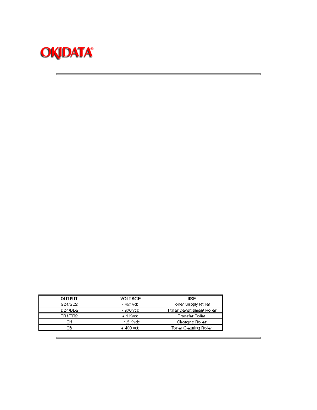
The following voltages are generated for use in the electro-static printing process.
Copyright 1997, Okidata, Division of OKI America, Inc. All rights reserved. See the OKIDATA Business
Partner Exchange (BPX) for any updates to this material. (http://bpx.okidata.com)
Page 52
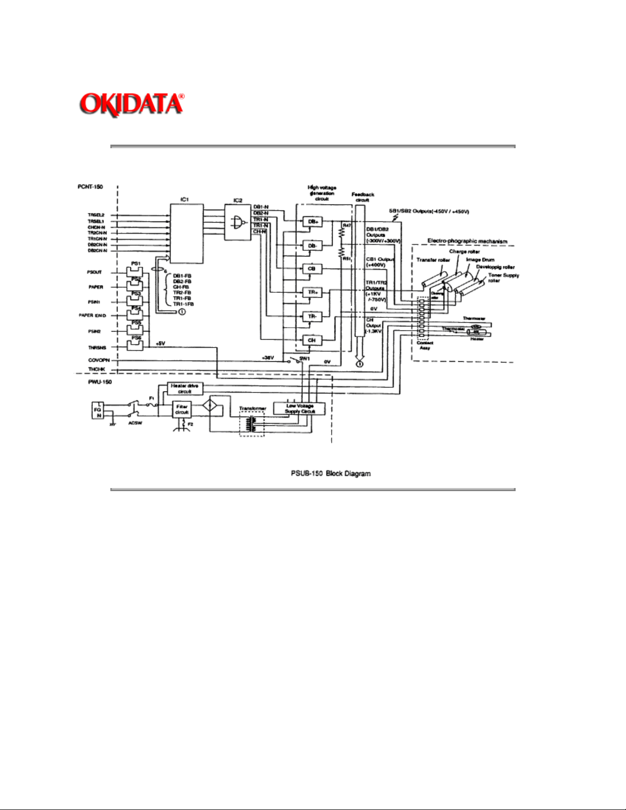
Sub-Power Supply Board Block Diagram
Page: 42
Service Guide OF1000
Chapter 2 Principles of Operation
Copyright 1997, Okidata, Division of OKI America, Inc. All rights reserved. See the OKIDATA Business
Partner Exchange (BPX) for any updates to this material. (http://bpx.okidata.com)
Page 53

Page: 43
Service Guide OF1000
Chapter 2 Principles of Operation
2.4.05 Fuser Unit
The fuser unit is controlled by a thermistor, the printer interface gate array, an LSI and the CPU to
keep the heat roller surface temperature within a predetermined range (about 150 degrees
Celsius). A thermal fuse within the fuser unit prevents abnormal temperature rises in case the
thermistor fails.
NOTE:
The CPU checks for an open circuit in the thermistor at power -on, setting a fuser alarm if this
error is detected.
The CPU also sets a fuser alarm if the proper temperature is not attained within a specified period
of time after power-on.
Upon detecting a fuser alarm, the CPU will halt (after printing the current page).
Copyright 1997, Okidata, Division of OKI America, Inc. All rights reserved. See the OKIDATA Business
Partner Exchange (BPX) for any updates to this material. (http://bpx.okidata.com)
Page 54

Page: 44
Service Guide OF1000
Chapter 2 Principles of Operation
2.4.06 Main Motor (Drum Motor)
The main motor is controlled by the motor control LSI, on the PCNT-150 board. The motor used is
a four-phase motor, driven by the two phase excited signal generated by the LSI.
Copyright 1997, Okidata, Division of OKI America, Inc. All rights reserved. See the OKIDATA Business
Partner Exchange (BPX) for any updates to this material. (http://bpx.okidata.com)
Page 55

Page: 45
Service Guide OF1000
Chapter 2 Principles of Operation
2.4.07 LED Array
Data for the 1,728 LEDs in the LED array is placed in the shift register by the HD CLK signal. The
data is loaded in the latch circuit by the HD LD signal.
Copyright 1997, Okidata, Division of OKI America, Inc. All rights reserved. See the OKIDATA Business
Partner Exchange (BPX) for any updates to this material. (http://bpx.okidata.com)
Page 56

Page: 46
Service Guide OF1000
Chapter 2 Principles of Operation
2.4.08 DC Fan
The fan is controlled by the FAN ON-P signal from the PCNT-150 board. In order for the
facsimiles printer to operate, the signal FAN SENSE-N must be active.
NOTE:
The fuser and the fan are not enabled when the cover is open. If the fan fails to run, the fuser will
turn off and the message
Copyright 1997, Okidata, Division of OKI America, Inc. All rights reserved. See the OKIDATA Business
Partner Exchange (BPX) for any updates to this material. (http://bpx.okidata.com)
PRINTER ALARM 4
will be displayed. Printing is disabled.
Page 57

Page: 47
Service Guide OF1000
Chapter 2 Principles of Operation
2.4.09 Registration Motor
The registration motor is driven clockwise for initial receive paper loading, then counterclockwise
for paper feeding. The motor is controlled by the motor drive IC on the PCNT-150 board.
Copyright 1997, Okidata, Division of OKI America, Inc. All rights reserved. See the OKIDATA Business
Partner Exchange (BPX) for any updates to this material. (http://bpx.okidata.com)
Page 58
Service Guide OF1000
Chapter 2 Principles of Operation
2.5 PRINTING PROCESS
2.5.01 General Information
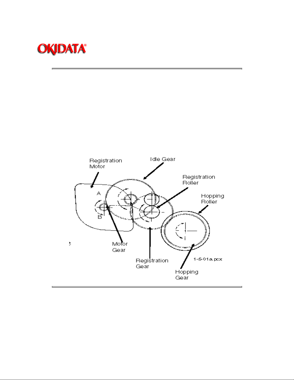
Hopping and feeding are controlled by a single registration motor.
Turning the registration motor in the "A" direction drives the hopping roller.
Turning the registration motor in the "B" direction drives the registration roller.
The registration gear and hopping gear contain one-way bearings. Turning each of these gears in
NOT
the reverse direction will
turn the corresponding roller.
Page: 48
Copyright 1997, Okidata, Division of OKI America, Inc. All rights reserved. See the OKIDATA Business
Partner Exchange (BPX) for any updates to this material. (http://bpx.okidata.com)
Page 59
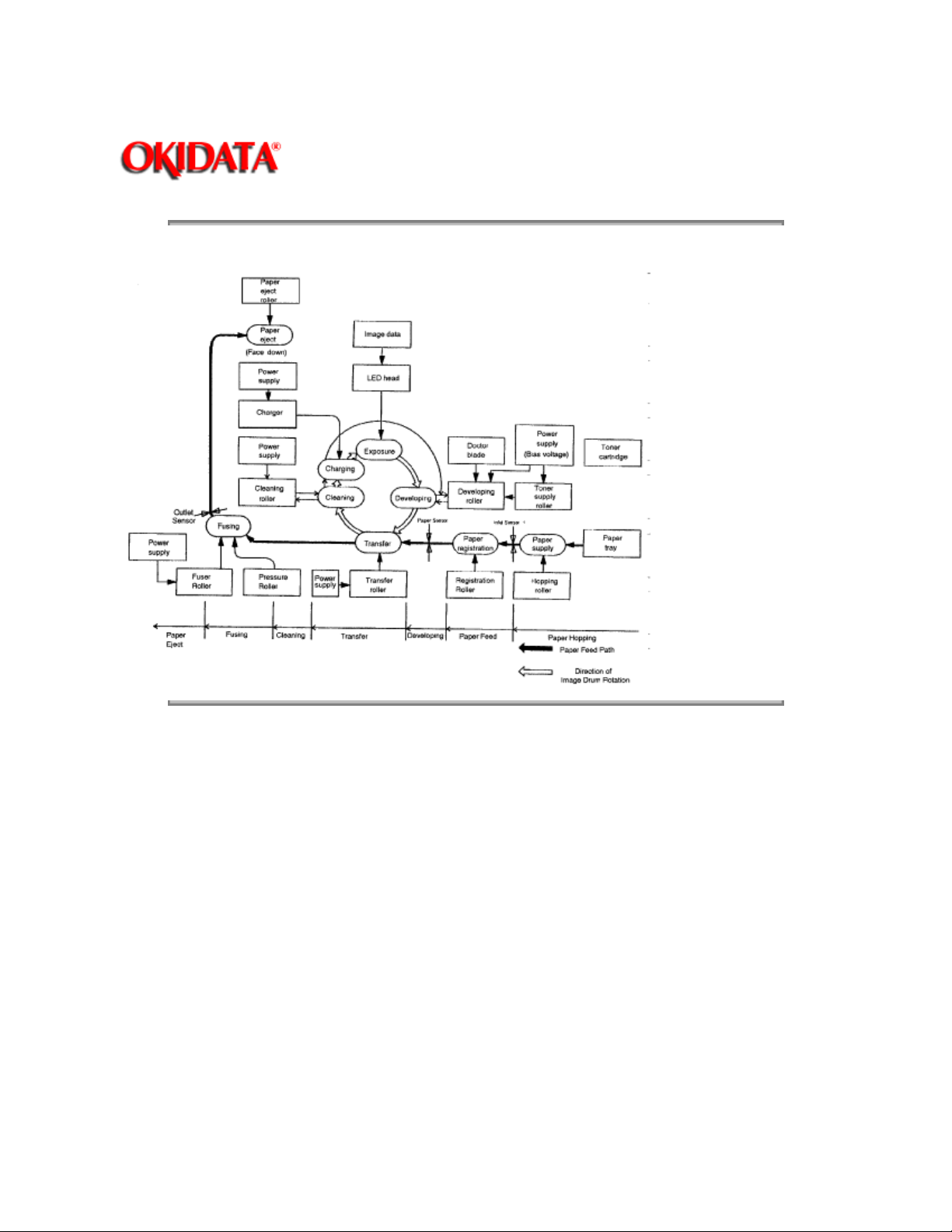
Printing Process Diagram
Page: 49
Service Guide OF1000
Chapter 2 Principles of Operation
Copyright 1997, Okidata, Division of OKI America, Inc. All rights reserved. See the OKIDATA Business
Partner Exchange (BPX) for any updates to this material. (http://bpx.okidata.com)
Page 60
Service Guide OF1000
Chapter 2 Principles of Operation
2.5.02 Hopping
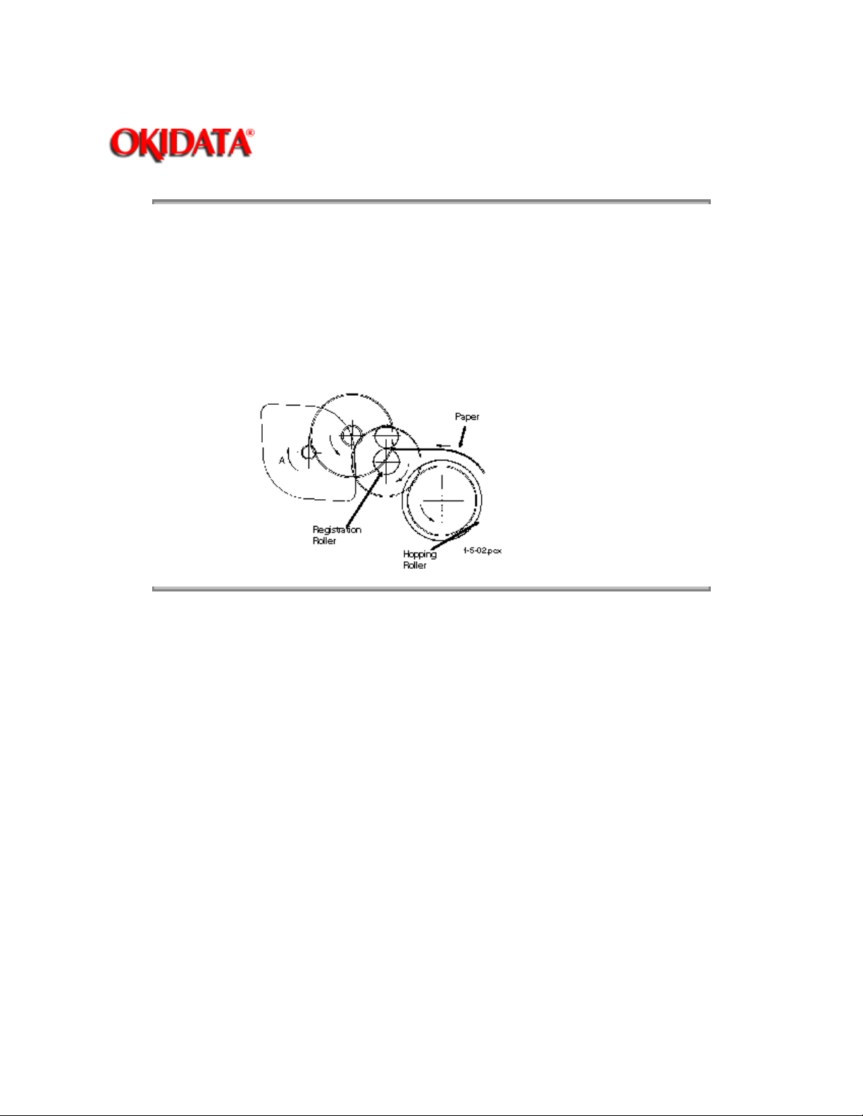
Hopping loads paper from the paper cassette.
During the hopping operation, the registration motor turns in a clockwise direction. This motor
drives the hopping roller, which in turn advances the paper until the inlet sensor 1 switches ON.
The registration gear turns, but the one-way bearing does not allow the registration roller to turn.
After inlet sensor 1 switches ON, the paper is advanced a predetermined length (until the paper
reaches the registration roller).
Page: 50
Copyright 1997, Okidata, Division of OKI America, Inc. All rights reserved. See the OKIDATA Business
Partner Exchange (BPX) for any updates to this material. (http://bpx.okidata.com)
Page 61
Service Guide OF1000
Chapter 2 Principles of Operation
2.5.03 Feeding
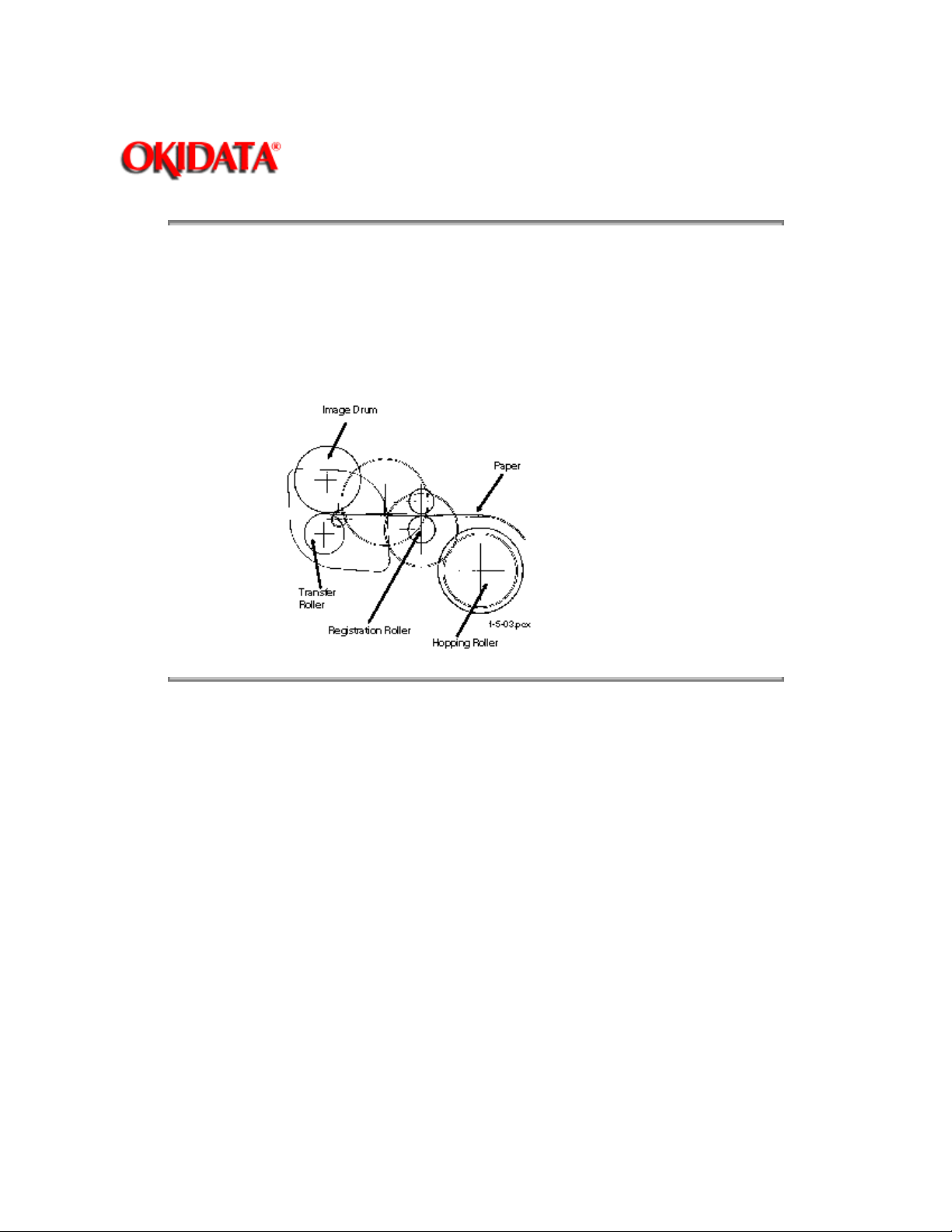
Feeding transports paper through the printer.
After the completion of hopping, the registration motor turns in a counter-clockwise direction. This
counter-clockwise motion drives the registration roller and advances the paper. The hopping gear
turns, but the one-way bearing does not allow the hopping roller to turn.
Page: 51
Copyright 1997, Okidata, Division of OKI America, Inc. All rights reserved. See the OKIDATA Business
Partner Exchange (BPX) for any updates to this material. (http://bpx.okidata.com)
Page 62
Service Guide OF1000
Chapter 2 Principles of Operation
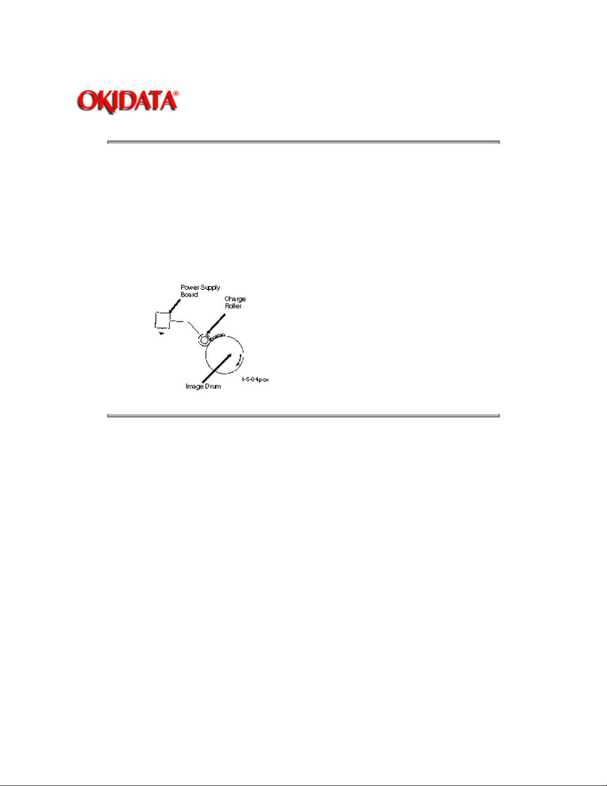
2.5.04 Charging
Charging applies -1.3 Kvdc to the charge roller. The charge roller contacts the image drum
surface.
The charge roller has two layers: a conductive layer and a surface protective layer. The surface
layer is flexible, which assures proper contact with the photosensitive drum.
The drum surface charges to approximately -750 vdc.
Page: 52
Copyright 1997, Okidata, Division of OKI America, Inc. All rights reserved. See the OKIDATA Business
Partner Exchange (BPX) for any updates to this material. (http://bpx.okidata.com)
Page 63
Page: 53
Service Guide OF1000
Chapter 2 Principles of Operation
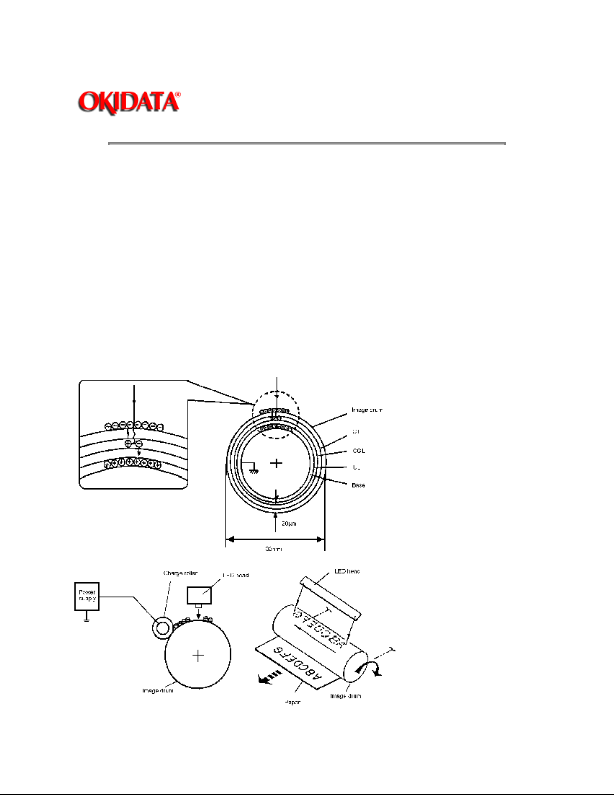
2.5.05 Exposing
The image drum has four layers.
· Carrier Transfer Layer (CTL)
· Carrier Generation Layer (CGL)
· Underlayer (UL)
· Aluminum Base
The CTL and CGL make up the organic photo conductor layer (OPC), which is about 20 micrometers (m
m) thick.
When light from the LED head irradiates the image drum surface, the light energy generates positive and
negative carriers in the CGL. The positive carriers are moved to the CTL by an electrical field acting on the
image drum. The negative carriers flow into the aluminum layer (ground).
The positive carriers moved to the CTL combine with the negative charges on the image surface
Page 64
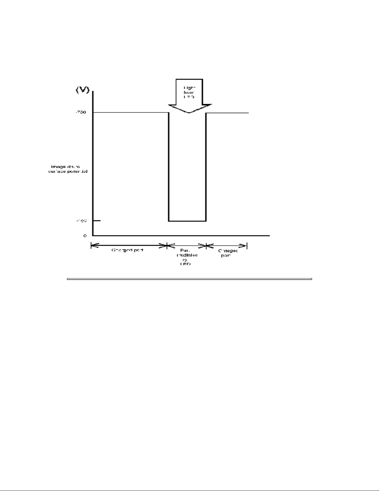
(accumulated by the contact charge of the charge roller), lowering the potential on the image drum
surface. The resultant drop in the potential of the irradiated part of the image drum surface forms an
electrostatic latent image on it. The surface potential on this irradiated part of the image drum is
approximately -100 vdc.
Copyright 1997, Okidata, Division of OKI America, Inc. All rights reserved. See the OKIDATA Business
Partner Exchange (BPX) for any updates to this material. (http://bpx.okidata.com)
Page 65
Service Guide OF1000
Chapter 2 Principles of Operation
2.5.06 Developing
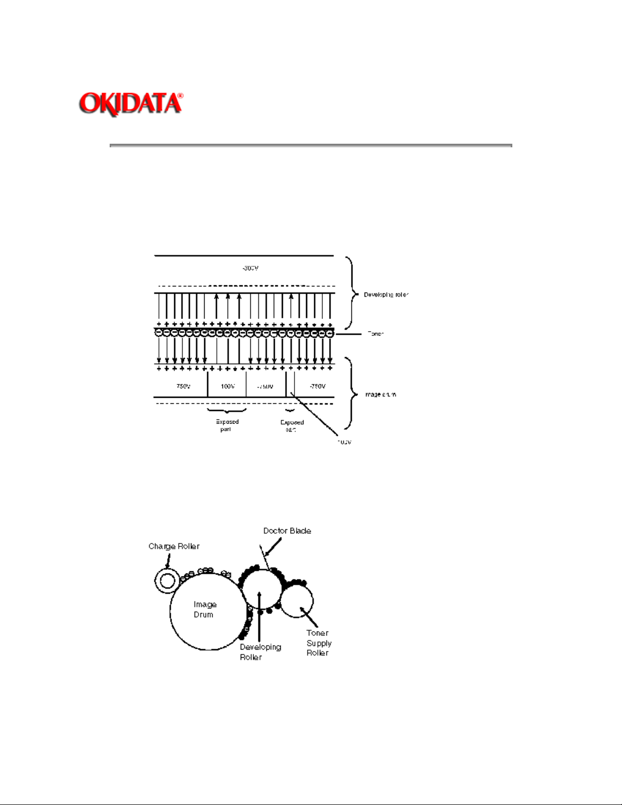
The electrostatic latent image formed on the image drum surface is developed into a visible image.
Developing takes place when contact is made between the image drum and the developing roller.
As the toner supply roller rotates, toner is absorbed into the sponge type roller material.
Page: 54
A charged particle will be attracted to a particle having a MORE POSITIVE charge than its own.
The developing roller surface is charged to -300 vdc and the toner supply roller is charged to -450 vdc.
Since the development roller is charged more positive than the toner supply roller, the toner on the toner
supply roller is attracted to the developing roller. The toner on the developing roller contacts the doctor
blade, forming a thin coat of toner on the developing roller surface.
The exposed portion of the image drum contains a more positive charge than the development roller (-100
vdc vs -300 vdc). Therefore, toner is attracted to the exposed areas of the image drum, making the
electrostatic latent image visible.
Page 66
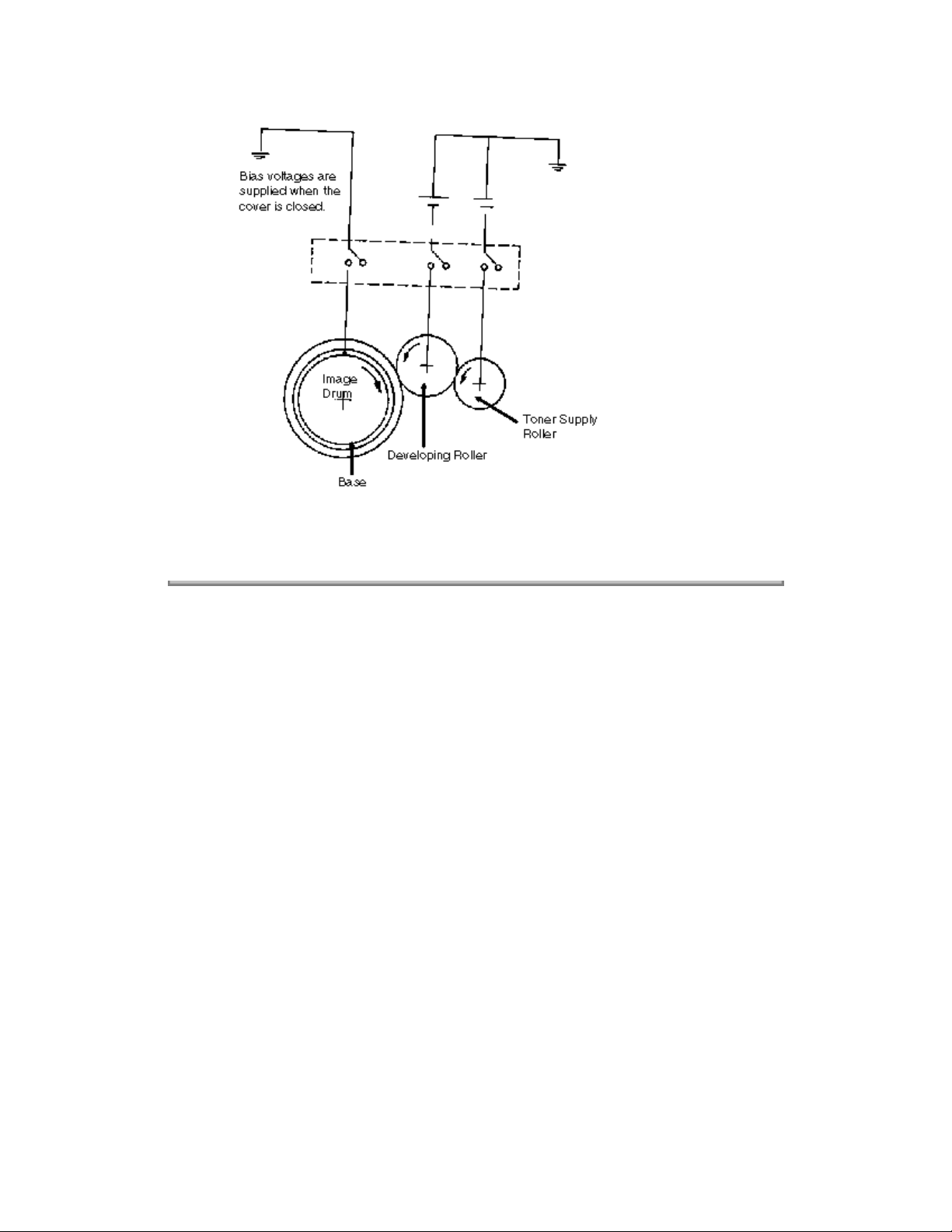
NOTE:
The toner supply roller and the developing roller are supplied with the bias voltages required
during the developing process. The toner supply roller is charged to -450 vdc. The developing
roller is charged to -300 vdc.
Copyright 1997, Okidata, Division of OKI America, Inc. All rights reserved. See the OKIDATA Business
Partner Exchange (BPX) for any updates to this material. (http://bpx.okidata.com)
Page 67
Service Guide OF1000
Chapter 2 Principles of Operation
2.5.07 Transfer
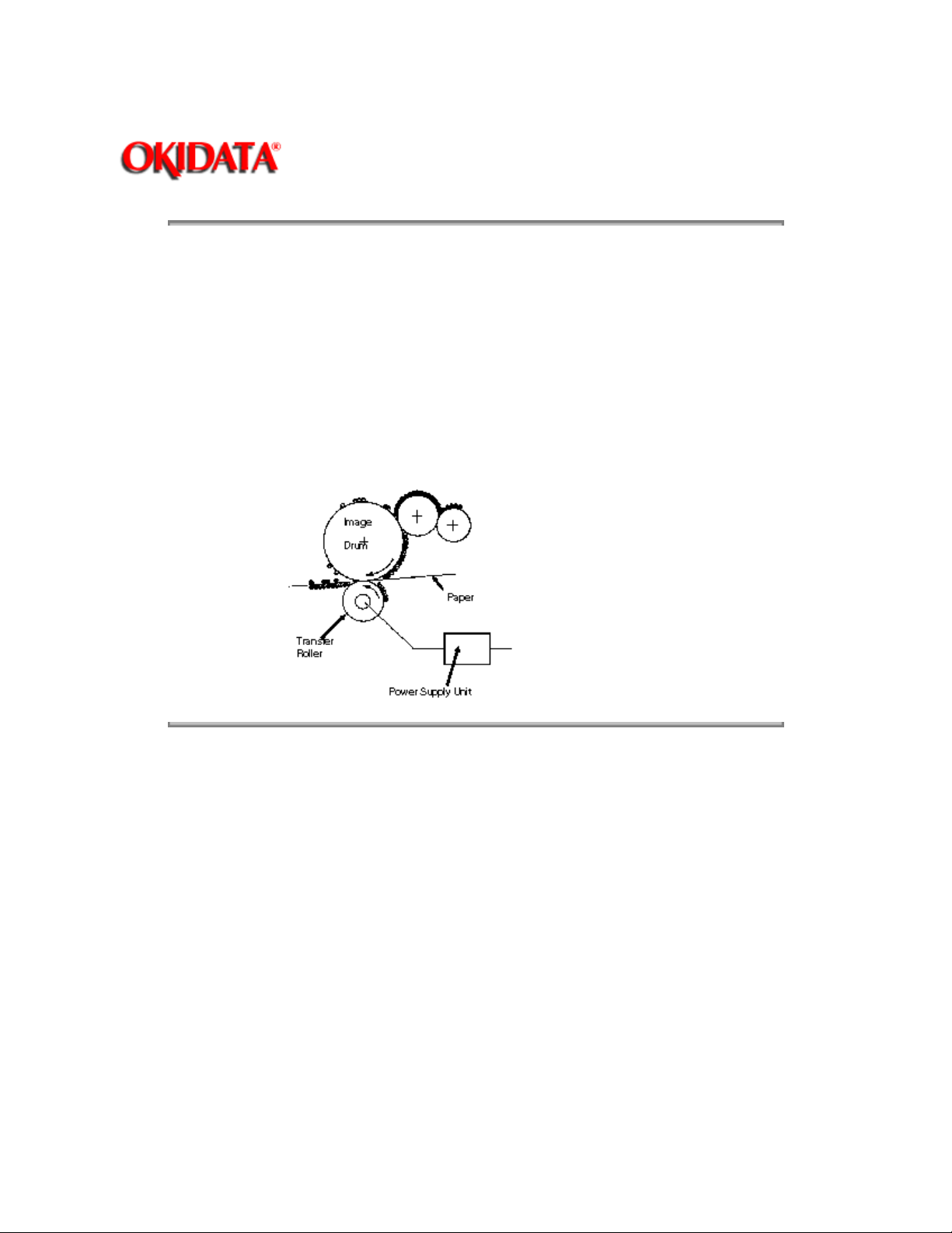
The transfer roller is made of a conductive sponge material. The roller keeps the paper in constant
contact with the image drum. Paper is placed over the image drum surface. A positive charge
(opposite in polarity to the toner) is applied to the paper from the reverse side.
A charged particle will be attracted to a particle having a MORE POSITIVE charge than its own.
A high positive charge is applied to the transfer roller by the power supply board. This induced
charge (on the surface of the transfer roller) is transferred to the paper when contact is made
between the transfer roller and the paper. The lower side of the paper is positively charged. The
negatively charged toner (on the photosensitive drum) is transferred to the upper side of the paper
because of the positive charge on the lower side of the paper.
Page: 55
Copyright 1997, Okidata, Division of OKI America, Inc. All rights reserved. See the OKIDATA Business
Partner Exchange (BPX) for any updates to this material. (http://bpx.okidata.com)
Page 68
Service Guide OF1000
Chapter 2 Principles of Operation
2.5.08 Fusing
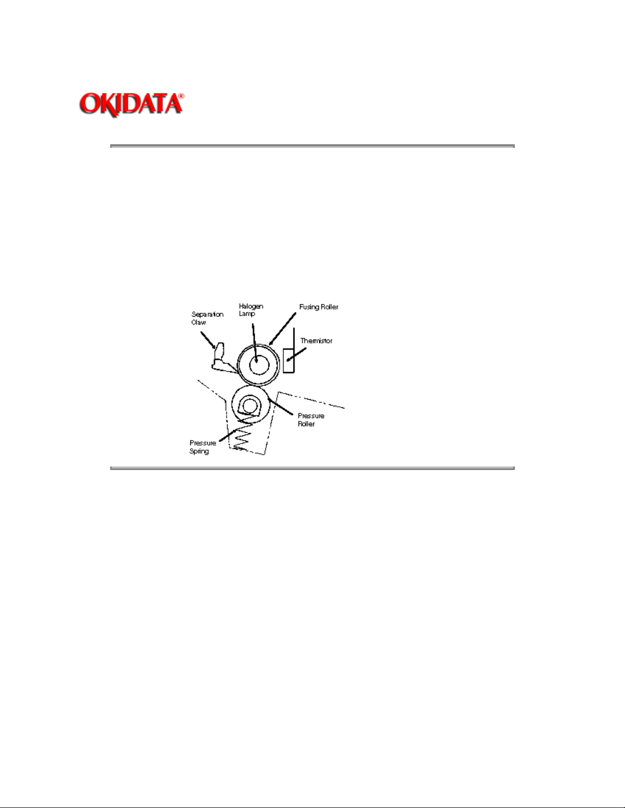
After transfer, the toner image is fused to the paper by heat and pressure. The paper passes
between the fusing roller and the pressure roller. The fusing roller has a teflon coating and
contains a 400 watt halogen lamp. A thermistor (which contacts the fusing roller) maintains the
fusing roller temperature at approximately 150 degrees Celsius. A thermostat cuts off the voltage
supply to the lamp if there is an abnormal temperature rise.
The pressure roller provides 2.5 Kg of pressure. This is generated by the pressure springs at each
side of the roller.
Page: 56
Copyright 1997, Okidata, Division of OKI America, Inc. All rights reserved. See the OKIDATA Business
Partner Exchange (BPX) for any updates to this material. (http://bpx.okidata.com)
Page 69
Page: 57
Service Guide OF1000
Chapter 2 Principles of Operation
2.5.09 Cleaning
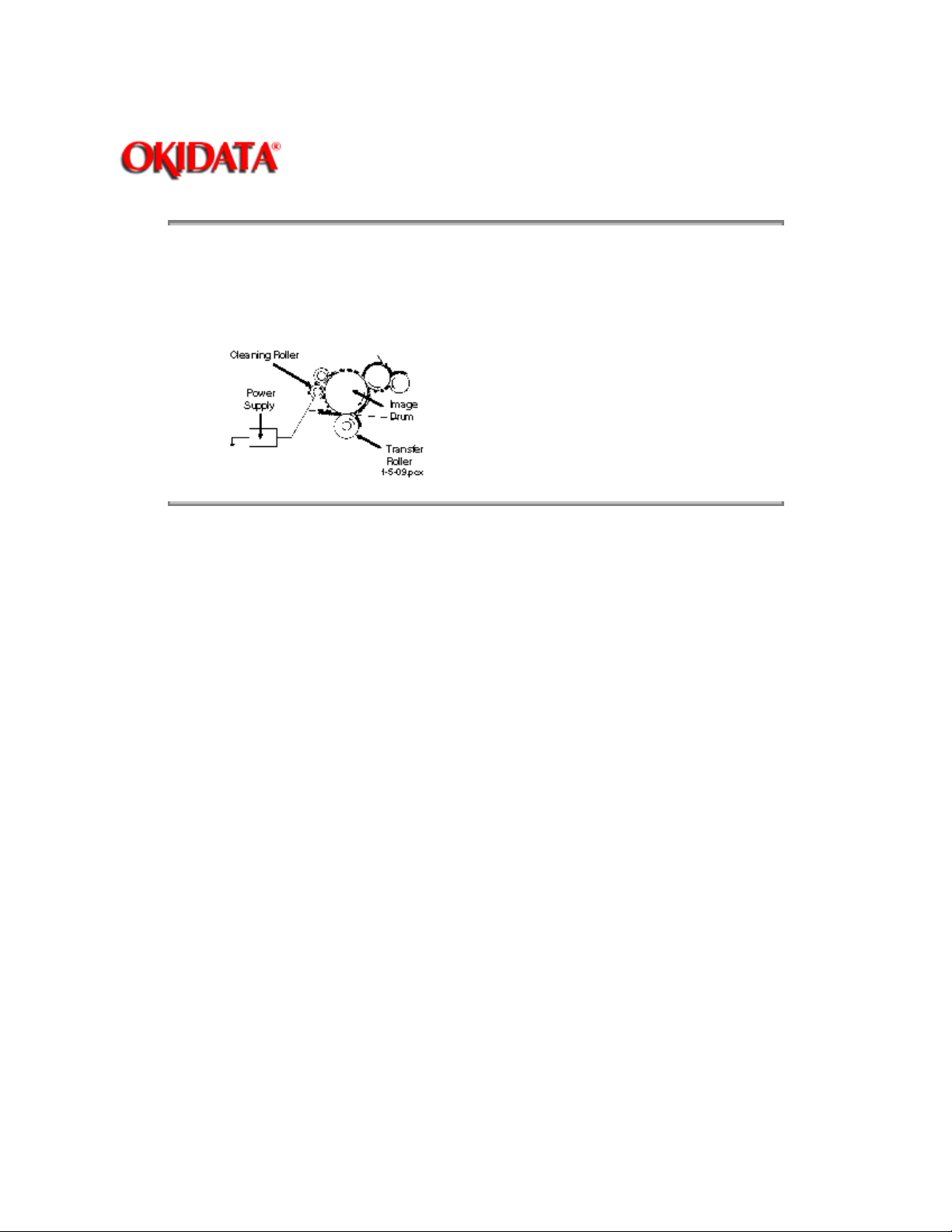
The image drum is cleaned at the end of transfer. The residual toner on the image drum is
attracted to the cleaning roller, which has a + 400 vdc static charge.
Copyright 1997, Okidata, Division of OKI America, Inc. All rights reserved. See the OKIDATA Business
Partner Exchange (BPX) for any updates to this material. (http://bpx.okidata.com)
Page 70
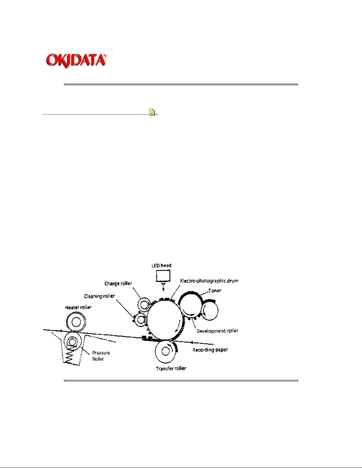
2.5.10 Printing
Page: 58
Service Guide OF1000
Chapter 2 Principles of Operation
Refer to the Printing Process Diagram
Printing is accomplished as follows.
· Approximately - 1.3 Kvdc is supplied to the charge roller. This causes the drum to charge to
approximately - 750 vdc.
· The LED head is turned ON in accordance with signals from the printer control board. This
causes a latent electrostatic image to be formed on the surface of the drum.
· Through the development process, a toner image replaces the electrostatic image.
· A + 1 Kvdc charge is applied to the transfer roller. This causes the toner image to be transferred
to the receive paper.
· Heat and pressure cause the toner image to become fused to the receive paper. The 150 degree
Centigrade fusing temperature is attained by turning a 400 watt halogen lamp ON. The fusing
temperature is controlled by a thermistor. In the event of a thermistor failure, a temperature fuse
will OPEN, turning off the quartz lamp, and preventing equipment damage.
· The residual toner is removed from the drum.
.
Copyright 1997, Okidata, Division of OKI America, Inc. All rights reserved. See the OKIDATA Business
Partner Exchange (BPX) for any updates to this material. (http://bpx.okidata.com)
Page 71

Page: 59
Service Guide OF1000
Chapter 2 Principles of Operation
2.6 SENSORS AND SWITCHES
2.6.01 Paper Jam Detection
Paper jam detection monitors the location of paper when the printer is powered ON and during printing. If
any of the following jams are present, the printing process is interrupted and the message PAPER JAM
will be displayed on the LCD.
To return to the printing process, the paper jam condition MUST be cleared. This is accomplished by
opening the upper cover, clearing the jam, and closing the cover.
Paper Outlet Jam
This jam occurs if,
NOT
· The paper does
period of time, however, the paper has already passed over the paper sensor.
Paper Size Error
The time interval between when the paper contacts the paper sensor and the outlet sensor determines
which size (length) paper is being used.
This error occurs if,
· The paper size of the loaded paper differs by + 45 mm or more from the paper
size set by the menu.
pass over the outlet sensor within a pre-determined
Cover Open Switch
When the stacker cover is opened, the cover open microswitch on the sub-power supply board
(PSUB-150) is deactivated. This disables the + 38 vdc and the high voltage power supply circuit. As a
result, all high voltage outputs are interrupted. At the same time, the CVOPN signal is sent to the main
control board (MCNT-150) to notify it of the OFF state of the microswitch. The MCNT-150 executes the
cover open routine. The operation panel displays the message COVER OPEN.
Copyright 1997, Okidata, Division of OKI America, Inc. All rights reserved. See the OKIDATA Business
Partner Exchange (BPX) for any updates to this material. (http://bpx.okidata.com)
Page 72
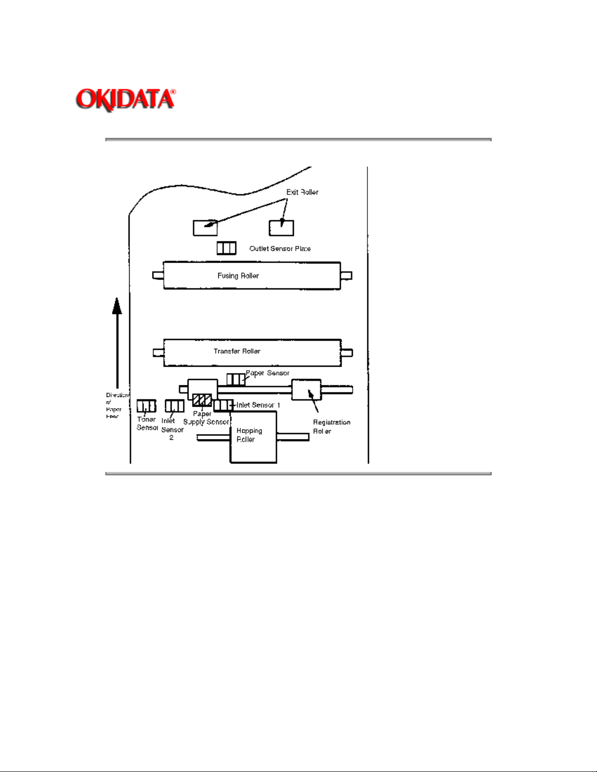
Sensor Location Diagram (Top View)
Page: 60
Service Guide OF1000
Chapter 2 Principles of Operation
Copyright 1997, Okidata, Division of OKI America, Inc. All rights reserved. See the OKIDATA Business
Partner Exchange (BPX) for any updates to this material. (http://bpx.okidata.com)
Page 73
Page: 61
Service Guide OF1000
Chapter 2 Principles of Operation
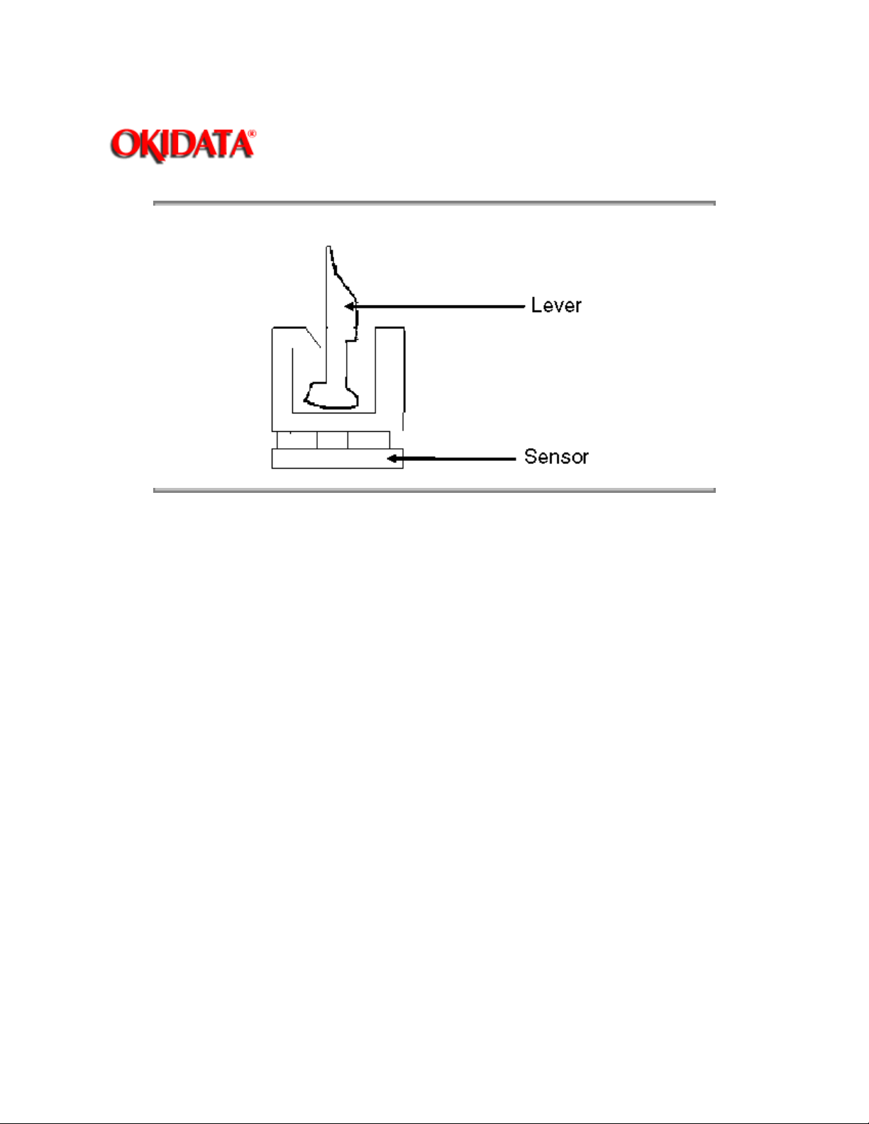
Detail of Sensor / Lever
`
Copyright 1997, Okidata, Division of OKI America, Inc. All rights reserved. See the OKIDATA Business
Partner Exchange (BPX) for any updates to this material. (http://bpx.okidata.com)
Page 74
Service Guide OF1000
Chapter 2 Principles of Operation
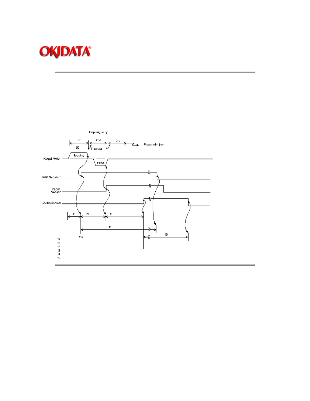
Paper Inlet Jam
This jam occurs when either of the following conditions occur.
· When the printer is powered ON, paper is at inlet sensor 1.
Page: 62
· After the hopping operation is attempted three times, the leading edge of the paper does
reach inlet sensor 1.
NOT
Copyright 1997, Okidata, Division of OKI America, Inc. All rights reserved. See the OKIDATA Business
Partner Exchange (BPX) for any updates to this material. (http://bpx.okidata.com)
Page 75
Service Guide OF1000
Chapter 2 Principles of Operation
Paper Feed Jam
This jam occurs when either of the following conditions occur.
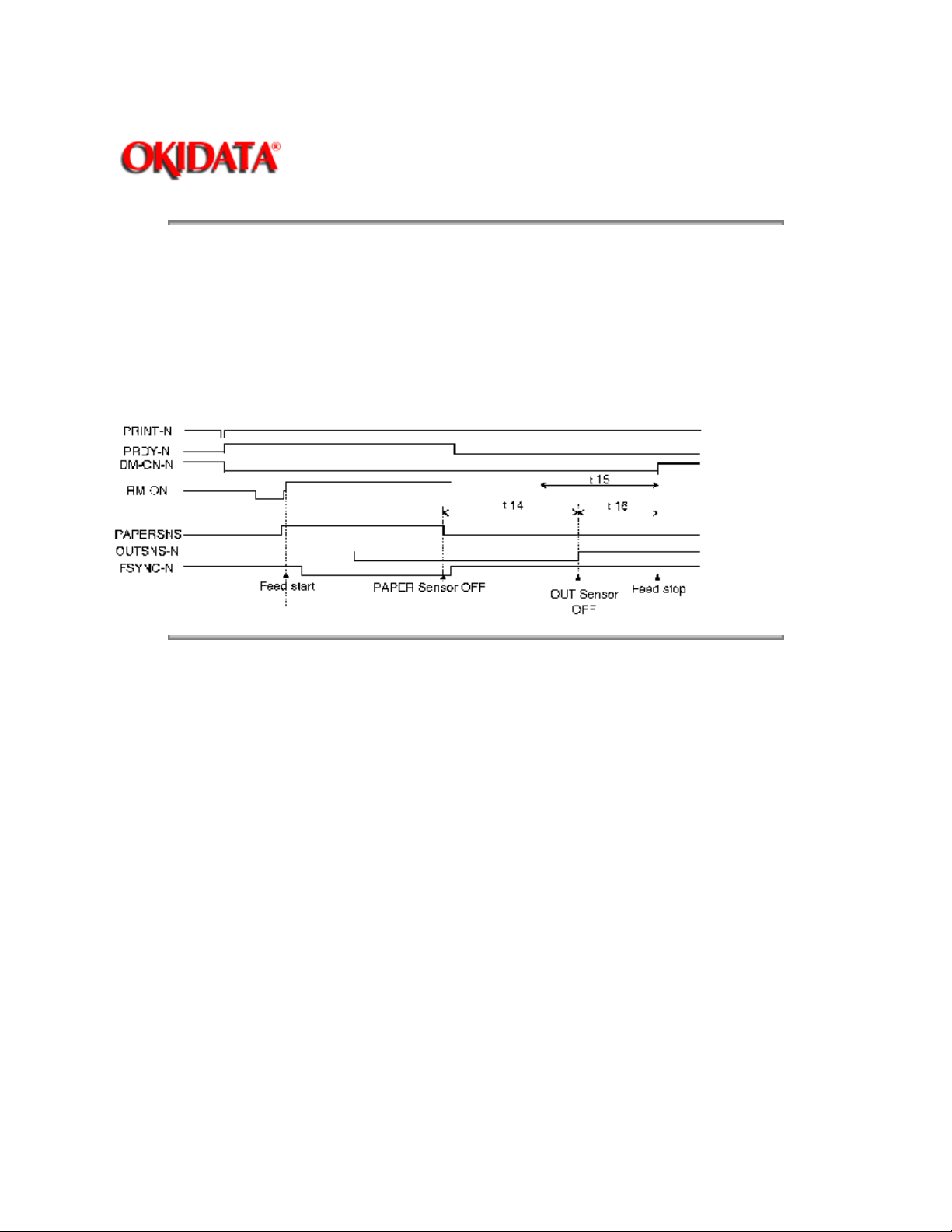
· The paper does not pass over the paper sensor within a pre-determined period of time.
· The leading part of the paper does not reach the outlet sensor within a pre-determined period of
time after the paper has passed over the paper sensor.
Page: 63
Copyright 1997, Okidata, Division of OKI America, Inc. All rights reserved. See the OKIDATA Business
Partner Exchange (BPX) for any updates to this material. (http://bpx.okidata.com)
Page 76

Service Guide OF1000
Chapter 2 Principles of Operation
2.6.02 Toner Low Sensor
The toner well of the image drum cartridge contains a toner agitator. Whenever the image drum
rotates, the toner agitator attempts to turn. A spring clip in the bottom of the toner well (along with
the proper amount of toner) holds the agitator at the bottom of the well. However, when toner is
distributed unevenly or an insufficient amount of toner is in the well, the toner agitator will rotate.
Therefore, as long as the toner well contains an adequate supply of evenly distributed toner, the
toner agitator will not rotate.
The toner sensor lever has a magnet embedded in it. Whenever the toner agitator is positioned at
the bottom of the toner well, the toner sensor lever is magnetically attracted to the toner agitator.
This causes the toner sensor lever to be lifted from the path of the toner sensor.
During a low toner condition (less than 20 grams of toner remaining), the toner agitator will rotate
continuously
operator panel will then display the TONER LOW message.
. This causes the toner sensor to turn ON / OFF as the image drum rotates. The
Page: 64
During an unevenly distributed toner condition, the toner agitator will rotate
distributed sufficiently
drum rotations. The operator panel will not display an error message since this is normal printer
operation.
If the toner sensor remains in an ON condition, the operator panel will display the TONER SNS
message.
Copyright 1997, Okidata, Division of OKI America, Inc. All rights reserved. See the OKIDATA Business
Partner Exchange (BPX) for any updates to this material. (http://bpx.okidata.com)
. This causes the toner sensor to turn ON / OFF for only a few image
until the toner is
Page 77

Page: 65
Service Guide OF1000
Chapter 3 Maintenance & Disassembly
3.1 MAINTENANCE
3.1.01 General Information
This section lists the parts replacement, adjustment, cleaning, and lubrication procedures.
Disassembly should not be performed unless absolutely necessary.
malfunctioning unit until you have followed the failure analysis procedures in Section Four of this Service
Handbook.
NEVER
perform disassembly on a
Follow the procedures listed in
adjustments may be required when either consumables or parts are replaced. Failure to perform these
procedures could result in unnecessary service calls.
The Okifax 1000 is a xerographic device. Cleaning procedures must be performed correctly if high print
quality is to be achieved.
3.1.02 Maintenance Tools
The following tools are required to service the unit.
· #2 Phillips screwdriver (with magnetic tip)
· Straight-slot screwdriver
· Needle nose pliers (4 inch)
· 5.5 mm wrench
· Digital multimeter
· Shop vacuum with toner filter
· Soft, lint-free cloth
· All-purpose cleaner
Adjustments and Service Settings
Counters may have to be reset and
.
· Dow Corning Molycoat BR-2 or Molycoat EM-30L or equivalent
3.1.03 Maintenance Precautions
· Do not disassemble the unit if it is operating normally.
· Before starting disassembly and assembly, always power OFF
the unit and detach the AC power cord.
· Detach the interface cable, if installed.
· Do not remove parts unnecessarily: try to keep disassembly to a minimum.
Page 78

· Use the recommended maintenance tools.
· When disassembling, follow the listed sequence.
Failure to follow the correct sequence may result in damaged parts.
· Since screws, collars and other small parts are easily lost, they
should be temporarily attached to the original positions.
· When handling circuit boards use extreme care.
Integrated circuits (microprocessors, ROM, and RAM) can be destroyed
by static electricity.
· Do not place printed circuit boards directly on conductive surfaces.
· Follow the recommended procedures when replacing assemblies and units.
Copyright 1997, Okidata, Division of OKI America, Inc. All rights reserved. See the OKIDATA Business
Partner Exchange (BPX) for any updates to this material. (http://bpx.okidata.com)
Page 79

Service Guide OF1000
Chapter 3 Maintenance & Disassembly
3.2 DISASSEMBLY/ASSEMBLY PROCEDURES
General Information
This section contains the disassembly procedures. Only the removal procedures are explained
here. Reverse the procedure for the installation.
At the bottom of each procedure is a listing of Okidata part numbers, item descriptions, and
cross-references to Appendix B. Items included in the Recommended Spare Parts List are
designated by the acronym RSPL. N/A will appear where a part number is not available.
This Service Handbook lists the disassembly procedures for major components of the unit. If you
decide to perform disassembly during this training, Okidata recommends that you perform
the disassembly procedures for RSPL items. All other procedures are provided to assist you in
identifying parts. It is not likely that you will perform these procedures while servicing the unit.
Be sure to read all notes, cautions, and warnings, as they contain important information regarding
disassembly / assembly.
only
Page: 66
Copyright 1997, Okidata, Division of OKI America, Inc. All rights reserved. See the OKIDATA Business
Partner Exchange (BPX) for any updates to this material. (http://bpx.okidata.com)
Page 80

Service Guide OF1000
Chapter 3 Maintenance & Disassembly
3.2.01 Preliminary Items
NOTES:
Refer to Section 3.4 of this Service Handbook for cleaning details.
Refer to Section 4.8 of this Service Handbook for Toner and Drum Counter Information.
1. Press the AC switch and power OFF the unit.
2. Detach the AC power cord.
3. Detach the modular telephone cord.
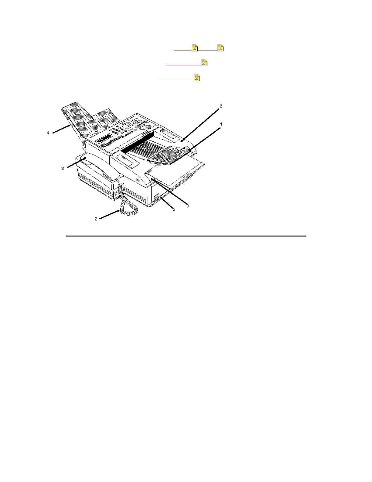
4. Remove the document support tray (1).
5. Remove the handset cord (2) and handset (3).
Page: 67
6. Remove the document stacker tray (4).
7. Remove the paper cassette assembly (5).
8. Raise the document table (6).
9. Press the buttons and raise the copy stacker (7).
10. Remove the image drum with toner cartridge.
P/N 56618901 Cord: AC Power
P/N 56621001 Cord: Modular Telephone
P/N 50103401 Tray: Document Support
P/N 56628101 Cord: Handset
P/N 53549709 Handset
P/N 50102001 Tray: Document Stacker
P/N 50101901 Cassette: Paper Assembly
RSPL B.2.01
RSPL B.2.16
RSPL B.2.01
RSPL B.2.01
RSPL B.2.01
RSPL B.2.16
, B2.16
RSPL B.2.01
P/N 70026101 Tray: Legal/Universal Paper Option (100 Sheet Capacity)
P/N 56116901 Kit: Image Drum Consumable
B.2.04
, B.2.20
B.2.18
Page 81
P/N 52106701 Kit: Toner Cartridge Consumable B.2.04 ,B.2.20
P/N 53571901 Cassette Separator Assembly
P/N 50925801 Spring: Cassette Separator
RSPL B.2.07
RSPL B.2.07
Copyright 1997, Okidata, Division of OKI America, Inc. All rights reserved. See the OKIDATA Business
Partner Exchange (BPX) for any updates to this material. (http://bpx.okidata.com)
Page 82

Service Guide OF1000
Chapter 3 Maintenance & Disassembly
3.2.02 LED Head
CAUTION
Do NOT touch the LEDs.
1. Perform this procedure:
3.2.01
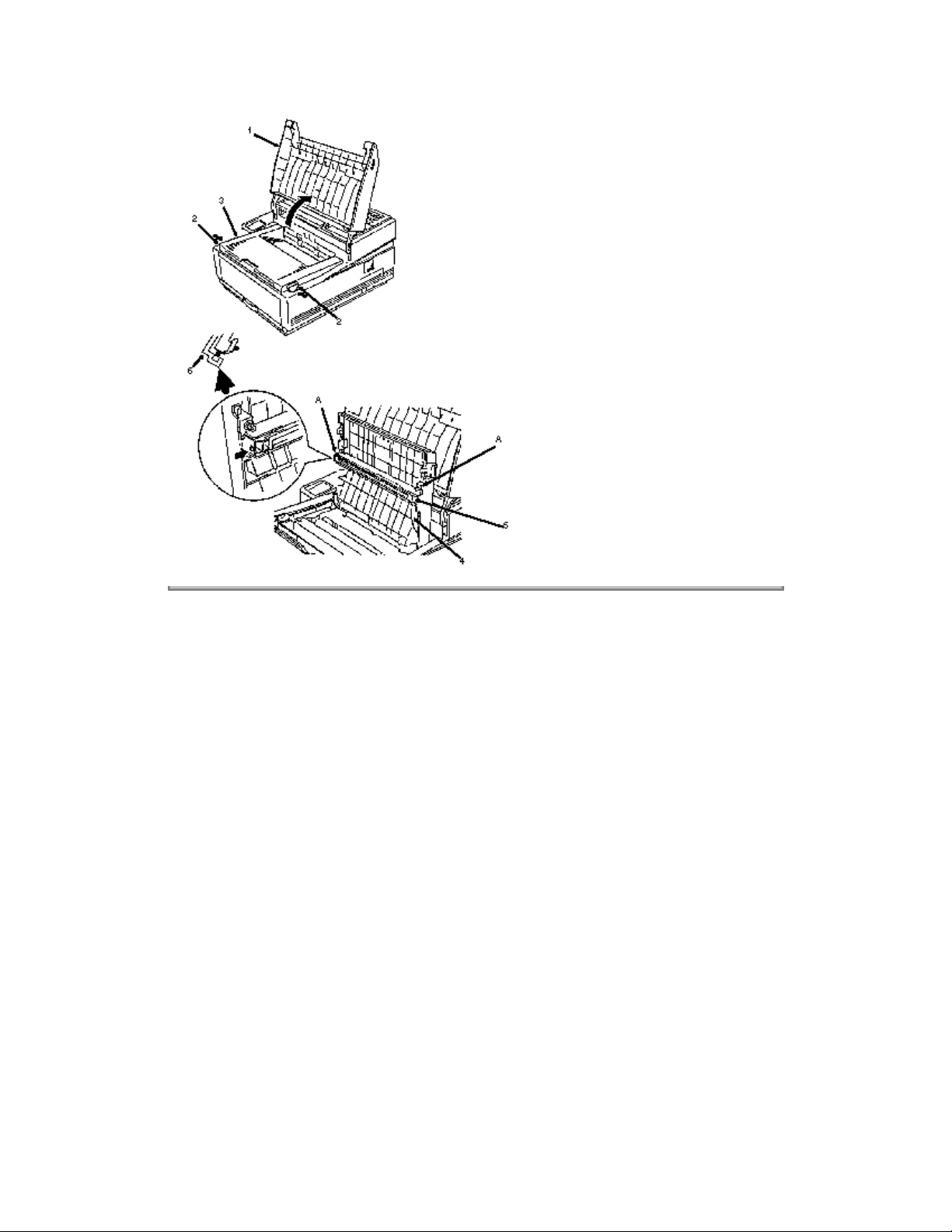
2. Raise the document table (1).
3. Press the buttons (2) and raise the copy stacker (3).
4. Detach the cable (4).
5. Press the copy stacker out at positions (A) and release the tabs of the LED head (5).
6. Remove the LED head, being careful not to lose the ground clip (6).
.
Page: 68
NOTES:
The Cable: LED-PCNT runs from the LED Head to connector CN4 of the PCNT board. This is a
flat white cable.
INSTALLATION
The blue strip of the cable faces the top of the unit.
When installing a new LED head, set the LED Head Drive Time.
Service Handbook for details .
Clean the LED head using the LED lens cleaner provided in the toner cartridge kit or use a lens
cleaning tissue and ethyl alcohol.
details .
P/N 56110801 LED Head
Refer to Section 3.4 of this Service Handbook for cleaning
RSPL B.2.04
Refer to Section 3.3 of this
Page 83
Copyright 1997, Okidata, Division of OKI America, Inc. All rights reserved. See the OKIDATA Business
Partner Exchange (BPX) for any updates to this material. (http://bpx.okidata.com)
Page 84

Service Guide OF1000
Chapter 3 Maintenance & Disassembly
3.2.03 Terminal Cover Cap, Rear Cover, and Fan
1. Perform this procedure:
3.2.01
2. Remove the screw (1).
3. Remove the terminal cap cover (2).
NOTE:
You do not have to remove the terminal cover cap to remove the rear cover and fan.
4. Remove the two screws (3).
5. Detach the rear cover (4) and tilt it out to access the fan cable (5).
6. Detach the fan cable from connector CN11 (6) from the board (PCNT) (7).
Page: 69
7. Release the latches (8) and remove the fan (9).
8. Remove the rear cover.
NOTES:
The fan connector cable goes to CN11 of the PCNT board. This is a 3 pin connector.
When installing the rear cover, be careful not to damage the ring volume switch cover.
When installing the fan, be careful not to leave the cable in front of the fan. Be sure to place the
cable on the side of the fan. If you do not, it may cause excessive vibration noise or prevent the
fan from operating. If fan motion is stopped completely, a PRINT ALARM 3 will be displayed on
the operator panel.
P/N N/A Screw
P/N 53070206 Cover: Terminal Cap
P/N 53070002 Cover: Rear
P/N 56510902 Fan
B.2.01
RSPL B.2.01
RSPL B.2.01
RSPL B.2.01
, B.2.16
Page 85
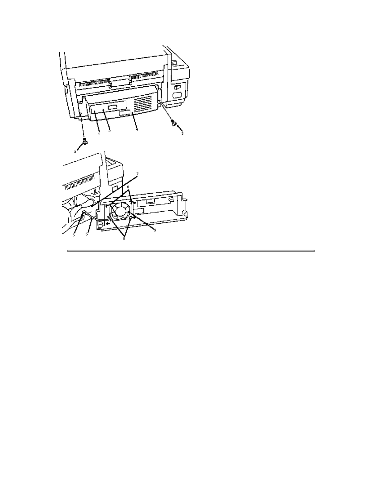
Copyright 1997, Okidata, Division of OKI America, Inc. All rights reserved. See the OKIDATA Business
Partner Exchange (BPX) for any updates to this material. (http://bpx.okidata.com)
Page 86
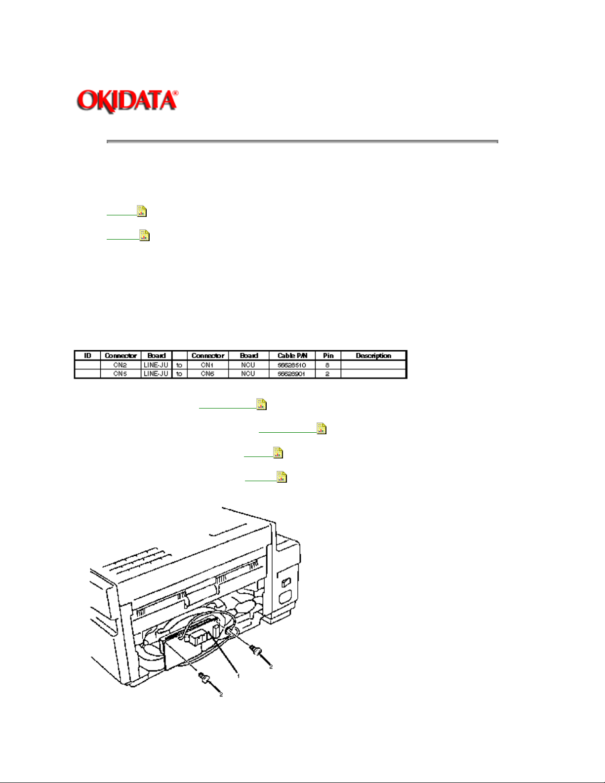
Service Guide OF1000
Chapter 3 Maintenance & Disassembly
3.2.04 Line Board (LINE-JU)
1. Perform these procedures:
3.2.01
3.2.03
2. Detach the cable to connector CN2 of the line board (LINE-JU) (1).
3. Detach the cable to connector CN5 of the board.
4. Remove the two screws (2).
5. Remove the board.
Page: 70
P/N 55073401 PCB: Line-JU
P/N 53070901 Cover: Ring Volume Switch
P/N 56628510 Cable: NCU-Line (8 pin)
P/N 56628901 Cable: NCU-Line (2 Pin)
RSPL B.2.07
B.2.16
B.2.16
RSPL B.2.07
Page 87

Copyright 1997, Okidata, Division of OKI America, Inc. All rights reserved. See the OKIDATA Business
Partner Exchange (BPX) for any updates to this material. (http://bpx.okidata.com)
Page 88
Service Guide OF1000
Chapter 3 Maintenance & Disassembly
3.2.05 Package Shelf Assembly
1. Perform these procedures:
3.2.01
3.2.03
3.2.04
2. Remove the four screws (1).
3. Pull the package shelf (2) out slightly.
4. Remove the three screws (3) holding the tie wraps down.
5. Detach the cables from the thirteen connectors (Not identified).
Page: 71
6. Remove the package shelf assembly, with boards.
P/N N/A Package Shelf Assembly
P/N N/A Bracket: Line
P/N N/A Guide: Package
P/N N/A Insulator (2)
P/N N/A Plate: Shield (L)
P/N N/A Screw
B.2.07
B.2.07
B.2.07
, B.2.08
, B.2.08
B.2.07
, B.2.08
B.2.07
B.2.07
, B.2.08
, B.2.08
, B.2.08
Page 89
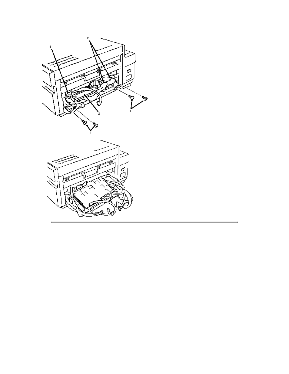
Copyright 1997, Okidata, Division of OKI America, Inc. All rights reserved. See the OKIDATA Business
Partner Exchange (BPX) for any updates to this material. (http://bpx.okidata.com)
Page 90
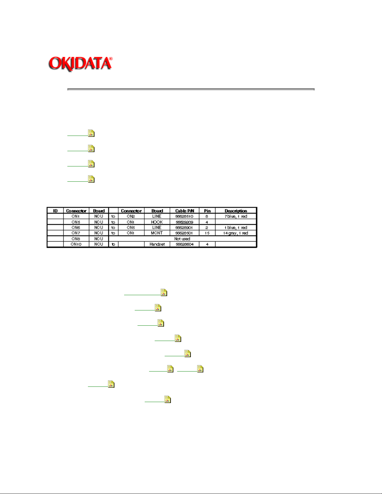
Service Guide OF1000
Chapter 3 Maintenance & Disassembly
3.2.06 Network Control Unit (NCU-U)
1. Perform these procedures:
3.2.01
3.2.03
3.2.04
3.2.05
2. Disconnect the cables from the connectors (see below).
Page: 72
3. Remove the three screws (1).
4. Remove the network control unit (NCU) (2).
P/N 55073501 PCB: NCU-U
P/N 56628510 Cable: NCU-Line
P/N 56629209 Cable: NCU-Hook
P/N 56628901 Cable: NCU-Line (2 Pin)
P/N 56628501 Cable: MCNT-NCU (15 Pin)
P/N 56628604 Cable: NCU-Hand Set
P/N N/A Screw
P/N 56628801 Cable: MCNT-PCNT
B.2.07
RSPL B.2.07
B.2.16
B.2.16
B.2.16
B.2.16
B.2.07, B.2.16
B.2.16
Page 91
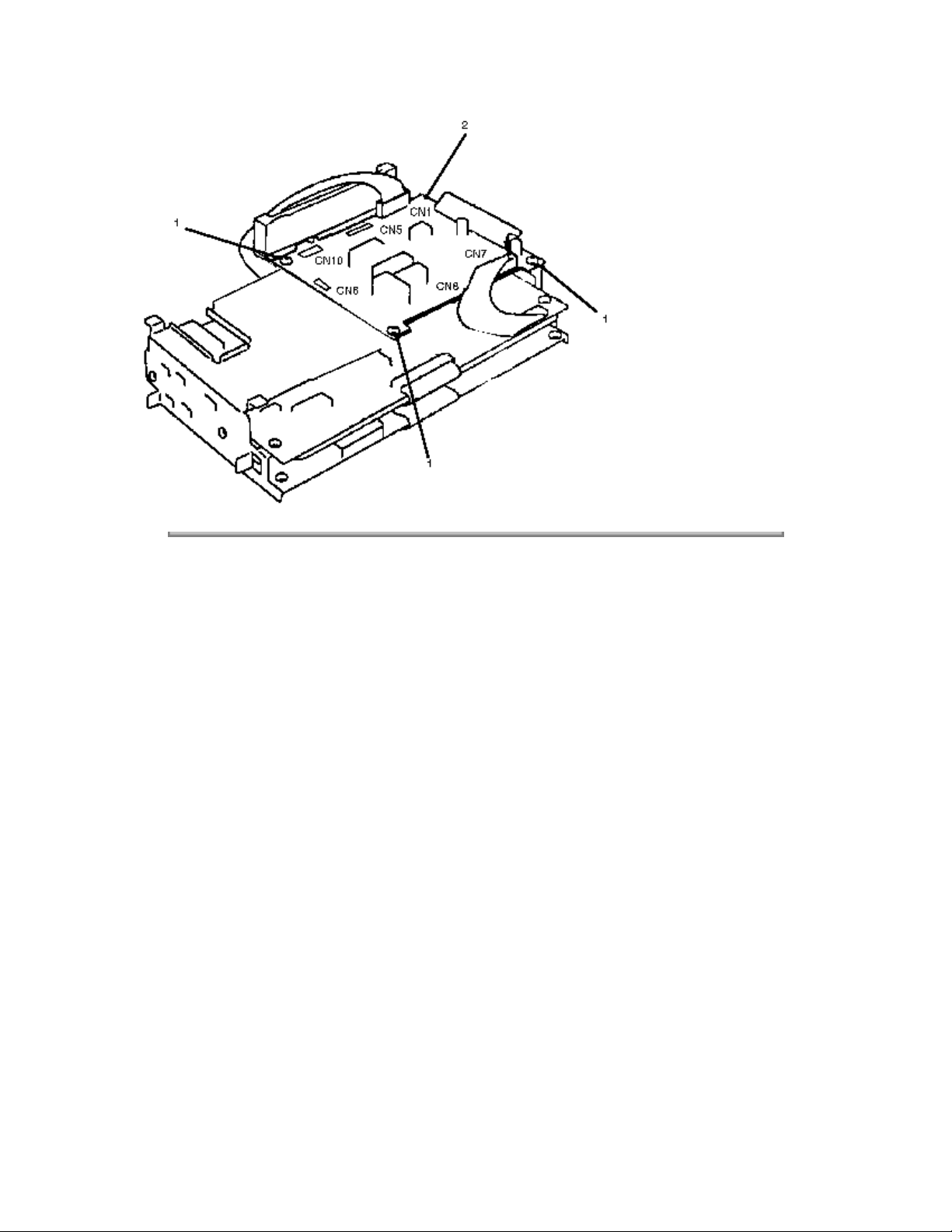
Copyright 1997, Okidata, Division of OKI America, Inc. All rights reserved. See the OKIDATA Business
Partner Exchange (BPX) for any updates to this material. (http://bpx.okidata.com)
Page 92
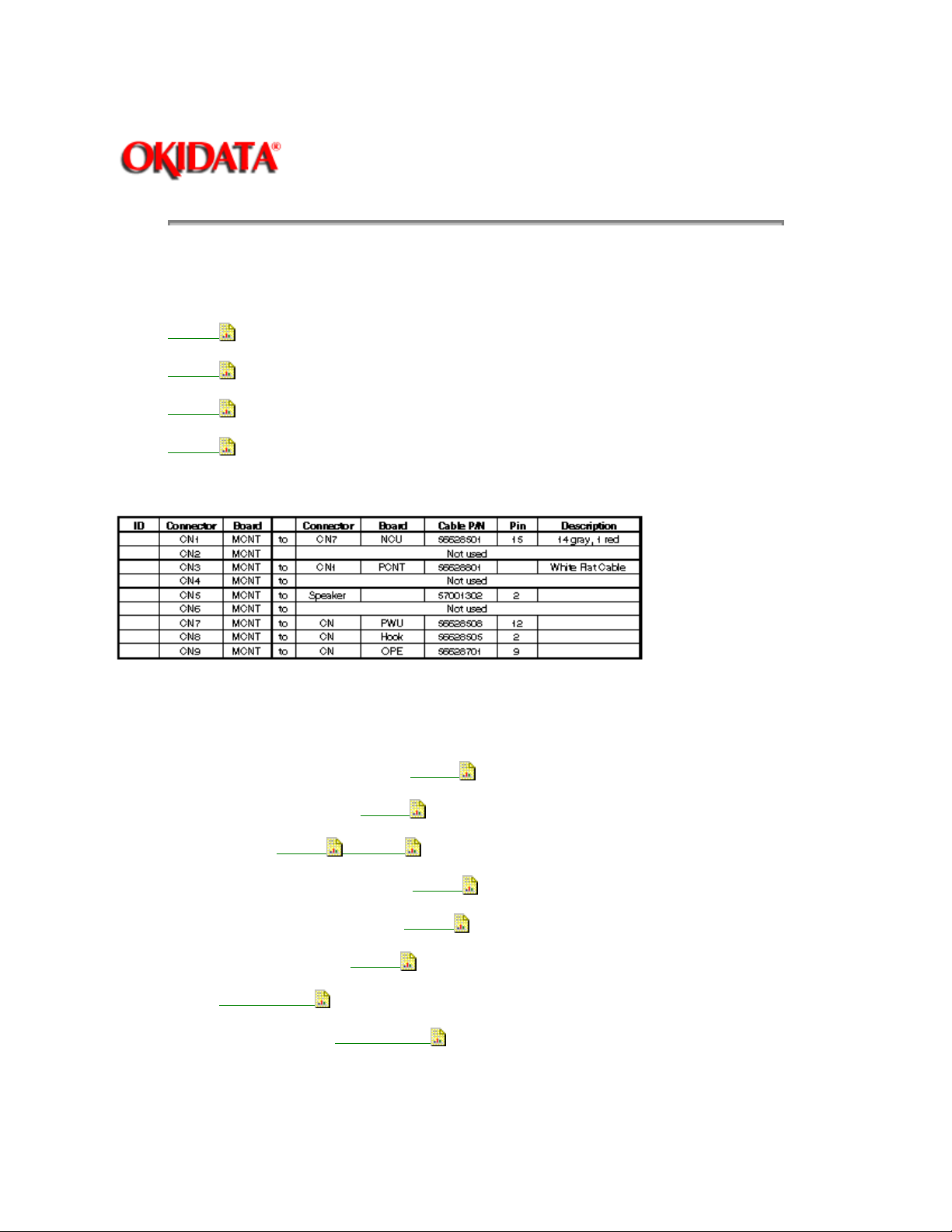
3.2.07 Main Control Board (MCNT-150)
1. Perform these procedures:
3.2.01
3.2.03
3.2.04
3.2.05
2. Detach the cables from connectors (see below).
Page: 73
Service Guide OF1000
Chapter 3 Maintenance & Disassembly
3. Remove the two screws (1).
4. Remove the main control board (2).
P/N 56628501 Cable: MCNT-NCU (15 Pin)
P/N 56628801 Cable: MCNT-PCNT
P/N 57001302 Speaker
P/N 56628508 Cable: MCNT-PWU (12 Pin)
P/N 56628505 Cable: MCNT-Hook (2 Pin)
P/N 56628701 Cable: OPE-MCNT
P/N N/A Screw
P/N 55073701 PCB: MCNT-150
RSPL B.2.07
B.2.02
B.2.16
, B.2.16
B.2.16
RSPL B.2.07
B.2.16
B.2.16
B.2.16
Page 93
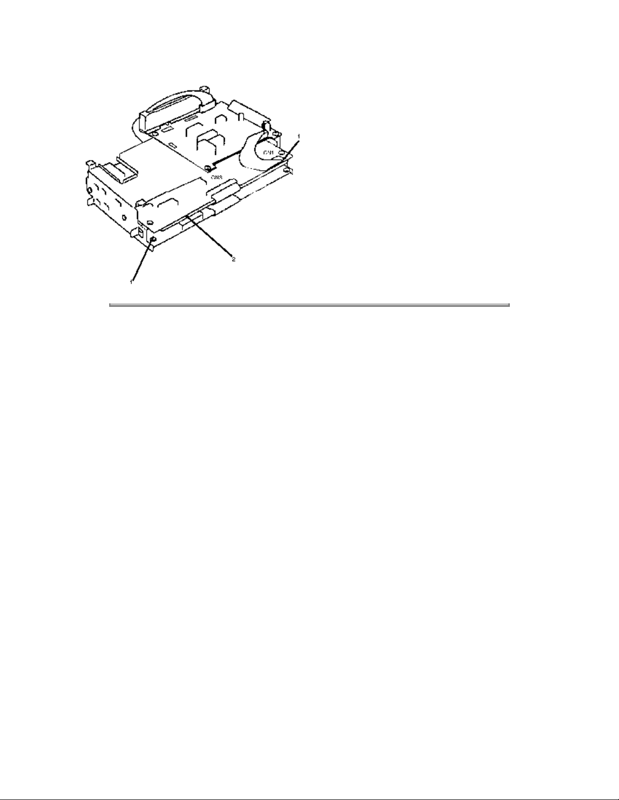
Copyright 1997, Okidata, Division of OKI America, Inc. All rights reserved. See the OKIDATA Business
Partner Exchange (BPX) for any updates to this material. (http://bpx.okidata.com)
Page 94
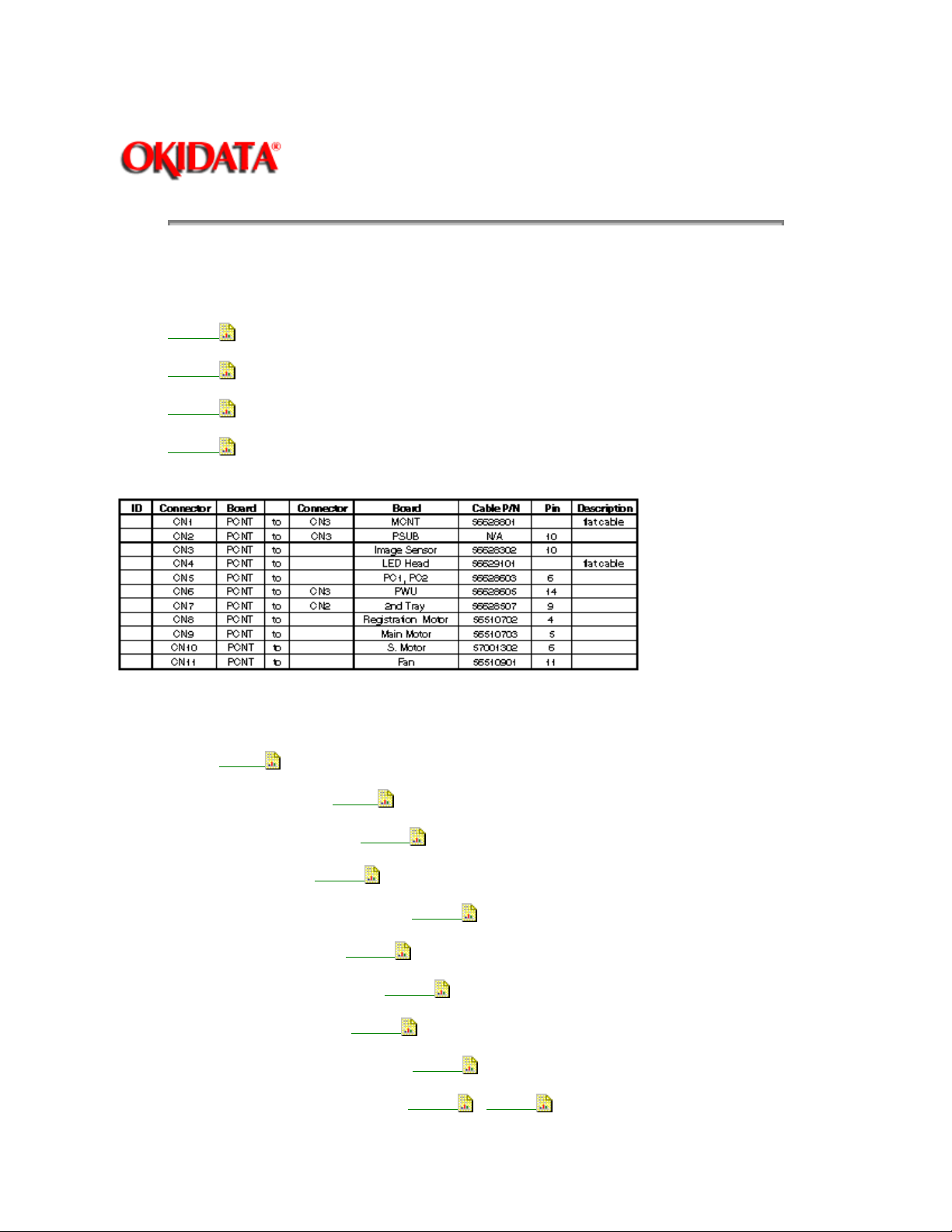
Chapter 3 Maintenance & Disassembly
3.2.08 Printer Control Board (PCNT-150)
1. Perform these procedures:
3.2.01
3.2.03
3.2.04
3.2.05
2. Detach the cables from the connectors (see below).
Page: 74
Service Guide OF1000
3. Remove the two screws (1).
4. Remove the printer control board (2).
P/N N/A Screw
P/N 55073601 PCB: PCNT-150
P/N 56628801 Cable: MCNT-PCNT
P/N N/A Cable: PCNT-PSUB
P/N 56628302 Cable: PCNT-Image Sensor
P/N 56629101 Cable: LED-PCNT
P/N 56628603 Cable: PC1+PC2-PCNT
P/N 56628605 Cable: PCNT-PWU
P/N 56628507 Cable: PCNT-2nd Tray PCB
P/N 56510702 Motor: Registration Stepper
B.2.07
B.2.07
B.2.16
B.2.17
B.2.17
B.2.17
B.2.17
B.2.17
B.2.17
B.2.05
B.2.17
,
Page 95
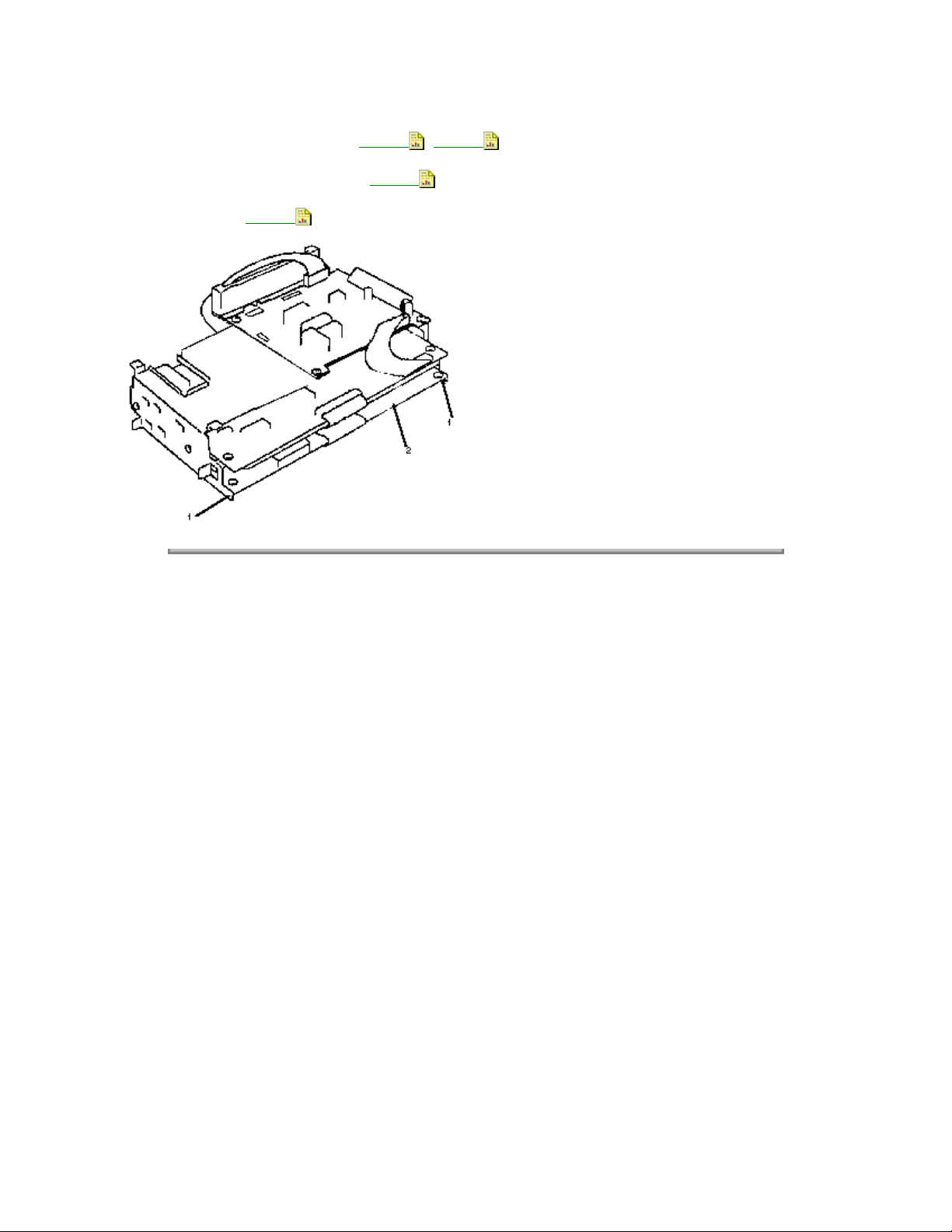
P/N 56510703 Motor: Main Stepper B.2.05 , B.2.17
P/N 57001301 Cable: PCNT-S Motor
P/N 56510902 Fan B.2.16
Copyright 1997, Okidata, Division of OKI America, Inc. All rights reserved. See the OKIDATA Business
Partner Exchange (BPX) for any updates to this material. (http://bpx.okidata.com)
B.2.17
Page 96
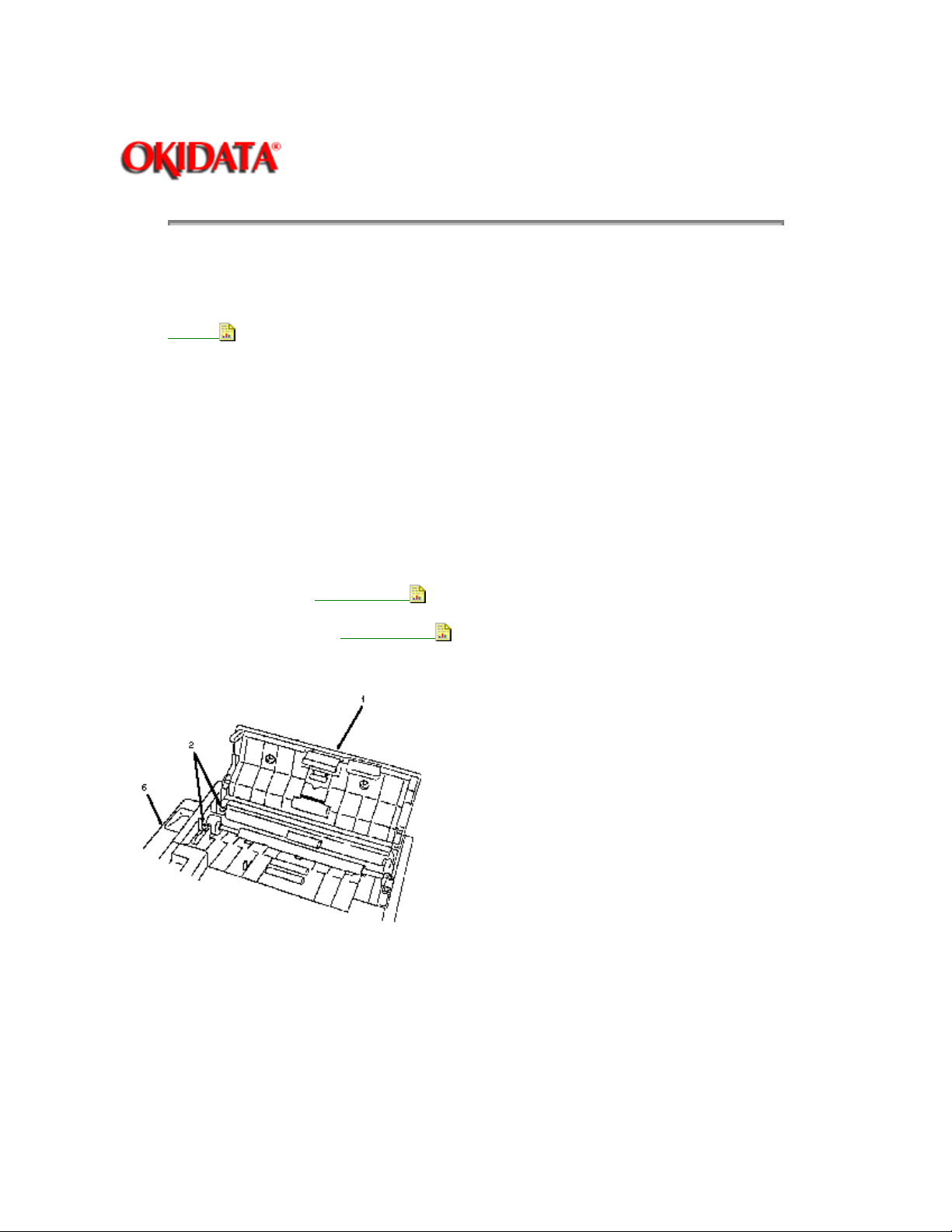
3.2.09 Left Side Cover
1. Perform this procedure:
3.2.01
2. Open the control panel unit (1).
3. Remove the two screws (2).
4. Open the document guide assembly (3).
5. Open the copy stacker (4).
6. Remove the screw (5).
7. Remove the left side cover (6).
Page: 75
Service Guide OF1000
Chapter 3 Maintenance & Disassembly
P/N 50317201 Cover: Cradle
P/N 53069901 Cover: Side (Left)
RSPL B.2.01
RSPL B.2.01
Page 97
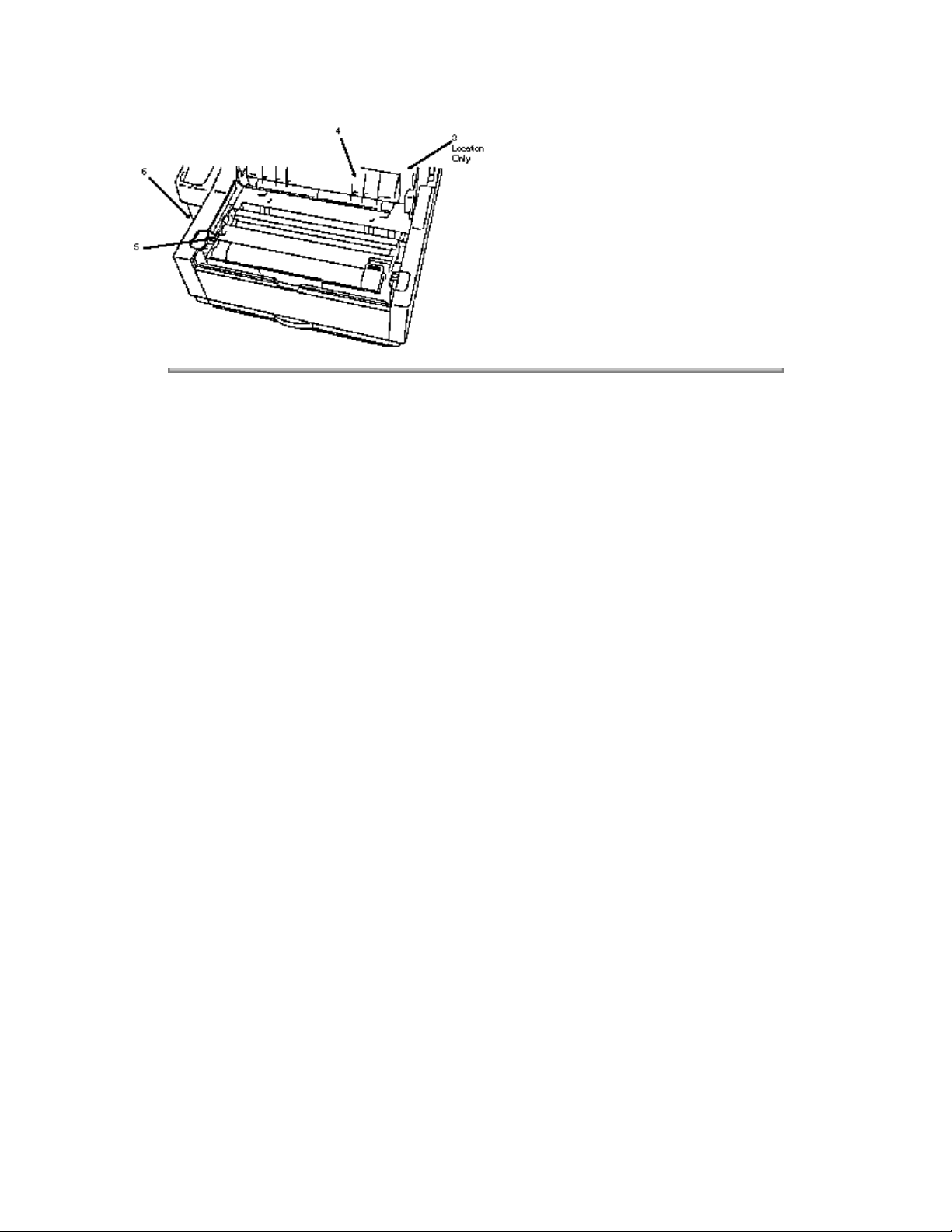
Copyright 1997, Okidata, Division of OKI America, Inc. All rights reserved. See the OKIDATA Business
Partner Exchange (BPX) for any updates to this material. (http://bpx.okidata.com)
Page 98
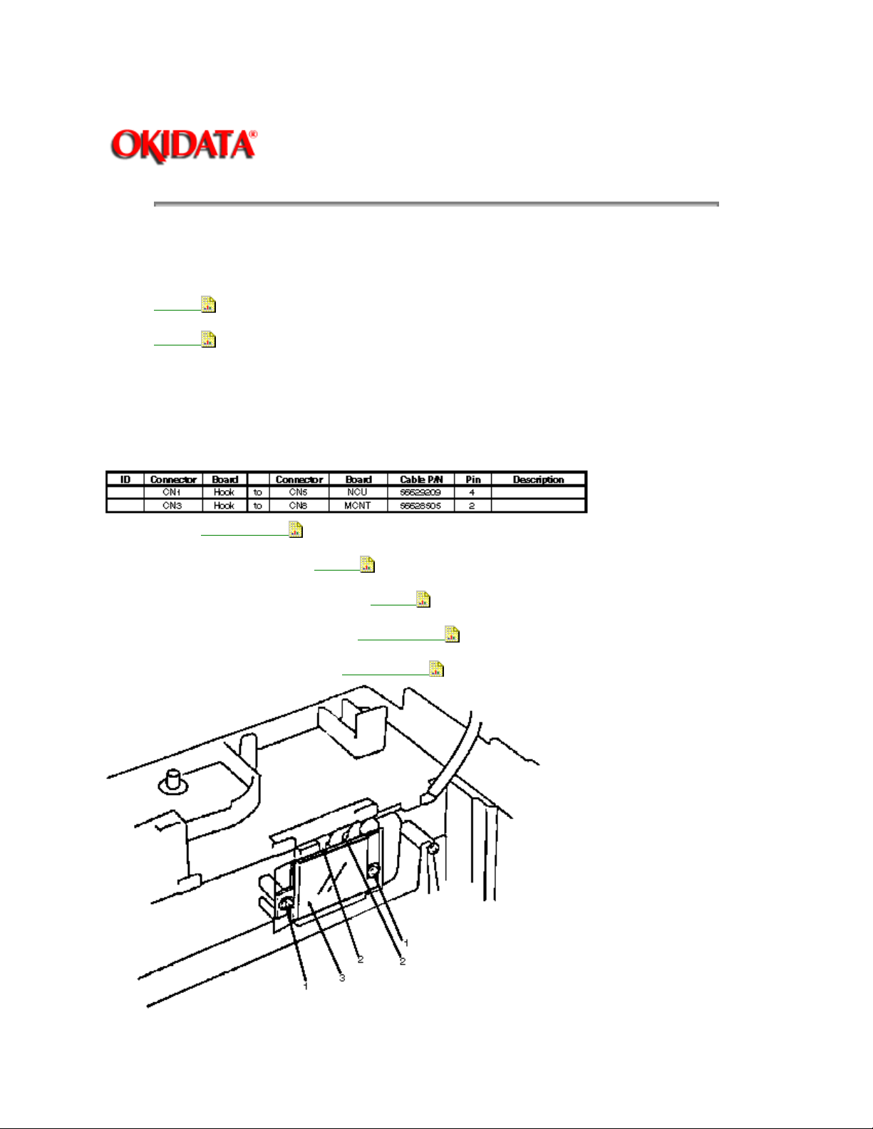
3.2.10 Hook Switch Board (Hook-SW)
1. Perform these procedures:
3.2.01
3.2.09
2. Remove the two screws (1).
3. Detach the two cables (2).
4. Remove the hook switch board (3).
Page: 76
Service Guide OF1000
Chapter 3 Maintenance & Disassembly
P/N N/A Screw
P/N 56629209 Cable: NCU-Hook
P/N 56628505 Cable: MCNT-Hook (2 Pin)
P/N 55074002 PCB: Hook Switch RSPL
P/N 51709801 Insulator: Hook Switch
RSPL B.2.01
B.2.16
RSPL B.2.01
RSPL B.2.01
B.2.16
Page 99

Copyright 1997, Okidata, Division of OKI America, Inc. All rights reserved. See the OKIDATA Business
Partner Exchange (BPX) for any updates to this material. (http://bpx.okidata.com)
Page 100
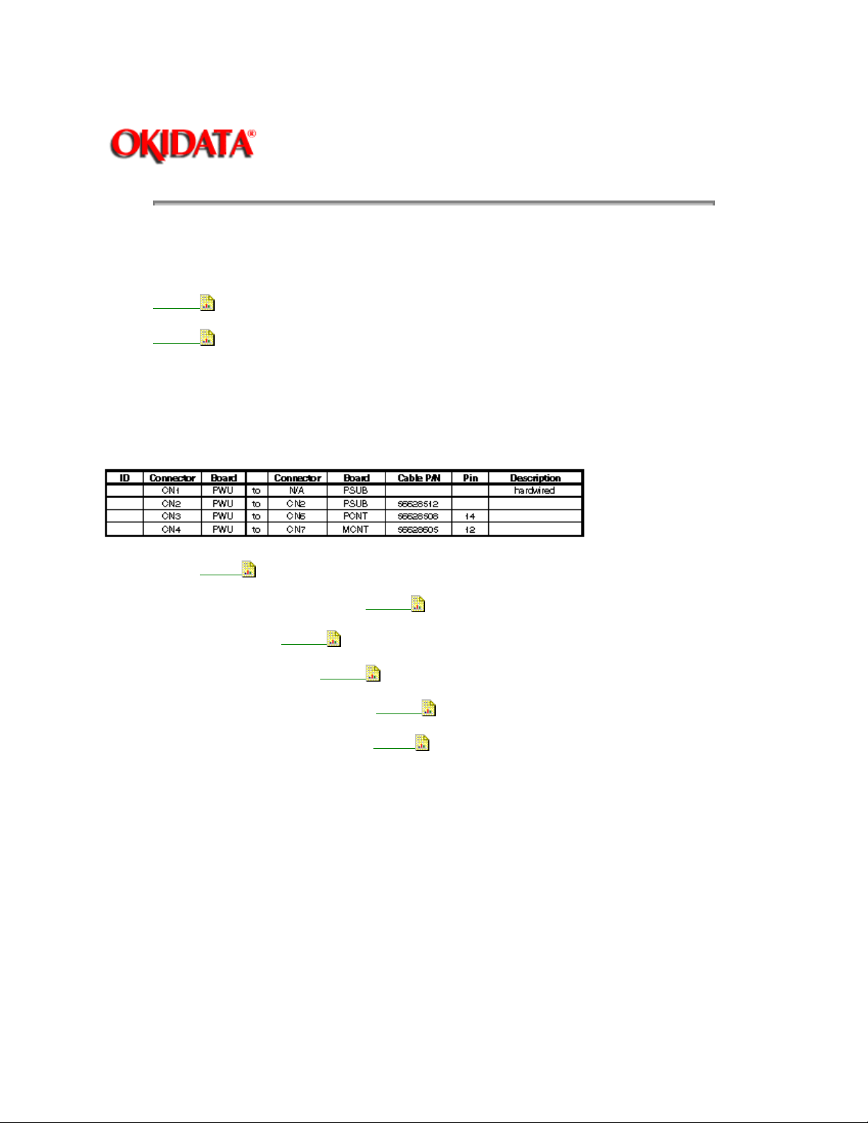
3.2.11 Power Supply Unit (PWU)
1. Perform these procedures:
3.2.01
3.2.09
2. Remove the two screws (1).
3. Disconnect the four connectors (see below).
4. Remove the power supply unit (2).
Page: 77
Service Guide OF1000
Chapter 3 Maintenance & Disassembly
P/N N/A Screw
P/N 56628512 Cable: PSUB-PWU (7 Pin)
P/N N/A Cable: PSUB-PWU
P/N 56628605 Cable: PCNT-PWU
P/N 56628508 Cable: MCNT-PWU (12 Pin)
P/N 56413101 Power Supply (120V) RSPL
B.2.07
B.2.17
B.2.17
B.2.16
B.2.16
B.2.07
 Loading...