

Page 1
Page: 1
Service Guide OF1050/2350/2450
Chapter 0 About This Manual
OKIFAX 1050 // 2350 // 2450
FACSIMILE PRODUCTS
Adobe Acrobat printable reference
copy of the OKIDATA Service Training Manual.
09/17/97
Note: This Adobe Acrobat version of the Okidata Service Training Manual was built with the
pictures rendered at 300 dpi, which is ideal for printing, but does not view on most
displays well.
Copyright 1997, Okidata, Division of OKI America, Inc. All rights reserved. See the OKIDATA Business
Partner Exchange (BPX) for any updates to this material. (http://bpx.okidata.com)
Page 2

Table of Contents Page
Service Guide OF1050/2350/2450
0 About This Manual
Front Cover 1
Federal Communications Commission Requirements for End
Users
FCC Telephone Consumer Protection Act 3
Canadian Department of Communications Requirements for
End Users
Federal Communications Commission Radio Frequency
Statement
Canadian Department of Communications Radio Interference
Statement
1 General Information
1.1 General Performance 7
1.2 General User's Function 8
1.3 General Maintenance Functions 9
1.4 General Appearance 10
....Figure 1.4.2 OKIFAX 1050 Control Panel 11
....Figure 1.4.3 OKIFAX 2350 Control Panel 12
....Figure 1.4.4 OKIFAX 2450 Control Panel 13
1.5 Basic Performance Specifications 14
1.6 Reports and Lists 15
....Reports and Lists - Continued 16
........Telephone Directory for OKIFAX 1050 (1/2): (Example) 17
........Telephone Directory for OKIFAX 1050 (2/2): (Example) 18
........Telephone Directory for OKIFAX 2350 (1/4): (Example) 19
........Telephone Directory for OKIFAX 2350 (2/4): (Example) 20
........Telephone Directory for OKIFAX 2350 (3/4): (Example) 21
........Telephone Directory for OKIFAX 2350 (4/4): (Example) 22
........Telephone Directory for OKIFAX 2450 (1/6): (Example) 23
........Telephone Directory for OKIFAX 2450 (2/6): (Example) 24
........Telephone Directory for OKIFAX 2450 (3/6): (Example) 25
........Telephone Directory for OKIFAX 2450 (4/6): (Example) 26
........Telephone Directory for OKIFAX 2450 (5/6): (Example) 27
........Telephone Directory for OKIFAX 2450 (6/6): (Example) 28
....Reports and Lists - Continued 29
2 Setup Information
2A-Setup Information 30
2.2 Site Selection 31
2.3 Unpacking 32
2.4 Check of Contents 33
2.5 Installation of Attachments 34
....Toner cartridge 35
2
4
5
6
Page 3

Table of Contents Page
....Recording paper 36
....Document stacker 37
2.6 AC Cord Connection 38
2.7 Telephone and Line Connections 39
2.8 Packing for Shipment 40
2B. Programming and Initial Settings 41
....2.9.2 Technical Functions 42
....2.9.2.02 TEL/FAX automatic switching 43
....2.9.2.03 TAD mode 44
........TEL/FAX mode flow chart 45
........TAD mode flow chart 46
........TAD mode flow chart 47
....2.9.3 Technical Functions Example 48
....2.9.3.02 Technical functions 49
........Table 2.9.2 (1/3) Technical Functions 50
........Table 2.9.2 (2/3) Technical Functions 51
........Table 2.9.2 (3/3) Technical Functions 52
....2.9.4 Users Functions 53
........Table 2.9.3 (1/6) Feature Specifications 54
........Table 2.9.3 (2/6) Feature Specifications 55
........Table 2.9.3 (3/6) Feature Specifications 56
........Table 2.9.3 (4/6) Feature Specifications 57
........Table 2.9.3 (5/6) Feature Specifications 58
........Table 2.9.3 (6/6) Feature Specifications 59
........Users Initial Settings 60
........Table 2.9.4 (1/3) One-touch key Program Settings 61
........Table 2.9.4 (2/3) One-touch key Program Settings 62
........Table 2.9.4 (3/3) One-touch key Program Settings 63
........Table 2.9.4 User Function Program Settings 64
....2.9.5 User's Functions Example 65
........Table 2.9.5 User's Functions 66
........2.9.5.02 Ring response time 67
........2.9.5.03 Dial parameters (In case the service bit is "OFF".) 68
....2.9.6 Clock Adjustment 69
....2.9.7 Dual Access Operation (for OKIFAX 2350/2450) 70
....2.9.8 System Data Programming 71
....2.9.9 One-Touch Key Programming 72
....2.9.10 Two-digit Auto Dial Programming 73
....2.9.11 Group setting 74
....2.9.12 Dial Parameters Settings 75
........2.9.12.02 Procedure 76
........Table 2.9.6 Dial Parameters Settings 77
....2.9.13 Programming Mail Box Password 78
....2.9.14 Memory Operations 79
Page 4

Table of Contents Page
........2.9.14.02 CONF. RX MSG. PRINT 80
....2.9.15 Off-line Tests 81
....2.9.16 On-line Tests 82
........2.9.16.02 Reception 83
............Fig. 2.9.5 Typical Transmission Flow 84
............Fig. 2.9.6 Typical Reception Flow 85
2C. Installation of Optional Units 86
....2.10.02 Procedure 87
........Installation of the memory board 88
........Installation of PCIU (PC interface) board 89
3 Board Description/Printer Operation
Section 1: Board Description - 3.1 Unit Configuration and Block
Diagram
....3.1.02 The unit configuration of the OKIFAX 2350/2450 is as
follows:
3.2 Overall Dimension and Mechanical Structure of OKIFAX
1050
3.3 Overall Dimension and Mechanical Structure of OKIFAX
2350/2450
3.4 Boards and Units 94
3.5 Function of Each Board 95
....3.5.02 Operation panel unit: YOPE (OKIFAX 1050)/YOPE-2
(OKIFAX 2350/2450) board
....3.5.03 NCUU board 97
....3.5.04 Power supply unit: FXVE (120V)/FXVH (230V) board 98
....3.5.05 MEMO (memory) board (Option) 99
....3.5.06 P050 board (Optional PC Interface) 100
....3.5.07 HOOK board (Optional handset) 101
....3.5.08 TELU board (Option): For US and Canada 102
....3.5.09 TQSB board (installed within second paper cassette
option)
........OKIFAX 1050 Block Diagram 104
........Figure 3.5.2 OKIFAX 2350/2450 Block Diagram 105
3.6 Explanation of Signal Flow for OKIFAX 1050/2350/2450 106
....3.7 Signal Flow by Mode of operation (OKIFAX 1050) 107
....Okifax 1050 300 bps Send Signal 108
....Okifax 1050 300 bps Receive Signal 109
....Okifax 1050 G3 Send Picture Signal 110
....Okifax 1050 G3 Receive Picture Signal 111
....Okifax 1050 Report Print Signal 112
3.8 Signal Flow by Mode of Operation (OKIFAX 2350/2450) 113
....Okifax 2350/2450 300 bps Send 114
....Okifax 2350/2450 300 bps Receive Signal 115
....Okifax 2350/2450 G3 Send Picture Signal 116
90
91
92
93
96
103
Page 5

Table of Contents Page
....Okifax 2350/2450 G3 Receive Picture Signal 117
....Okifax 2350/2450 Report Print Signal 118
3.9 Power Supply Unit 119
....General functional description 120
....3.9.02 Power Supply Unit (FXVE/FXVH) 121
....3.9.03 FXVE (for 120 V)/FXVH (for 230 V) Circuit Diagram
(2/2)
3.10 NCU Board 123
3.11 TELU Circuit Diagram (option) 124
....Block Diagram of TEL-U (option) 125
....Relationship between NCUU and TEL-U 126
3.12 MEMO (memory) Circuit Diagram (option) 127
3.13 P050 (PC interface unit) Circuit Diagram (option) 128
3.14 TQSB (Second tray) Circuit Diagram: option 129
Section 2: Print Operation - 3.15 Mechanical Components 130
....Layout of Print Station Components 131
3.16 Process Operations 132
....3.16.02 Charging 133
....3.16.03 Exposure 134
....3.16.4 Developing 135
....3.16.05 Transfer 136
....3.16.06 Fusing 137
....3.16.07 Cleaning 138
....3.16.08 Cleaning of rollers 139
3.17 Actual Electo-photographic Process 140
3.18 Errors List 141
3.19 Major Trouble Errors 142
3.20 Cleaning 143
3.21 Sensors and Switches 144
....3.21.02. Sensors and switch control 145
4 Mechanical Disassembly and Reassembly
4.1 General 146
....4.1.2 Tools 147
4.2 How to Disassemble and Reassemble 148
....4.2.1 LED Print Head 149
....4.2.2 Image Drum, Rear Cover, NCU Cover, Main Cover,
Separation Plate, NCU Board, Modem Board
....4.2.3 Control Panel Assembly, Paper Guide (U) Assembly. 151
....4.2.4 Sub-roller, ADF Roller Assembly, Pinch Roller, Contact
Image Sensor, Document Detectors (PC1 and PC2).
....4.2.5 Registration Stepper Motor, Main Stepper Motor,
release Guide Assembly, Eject Roller Assembly, Manual Guide
Assembly (only for OKIFAX 2350/2450), Stack Cover, Fusing
Unit
122
150
152
153
Page 6

Table of Contents Page
....4.2.6 Lower Base, Motor Assembly, Back-up Roller, Transfer
Roller, Reset Levers
....4.2.7 Registration Roller, Hopping Roller, Sensor Plates 155
....4.2.8 MCNT Board, Power Supply Unit, Contact Assembly,
Transformer
5 Adjustments
5.1 Setting of LED Print Head Drive Time 157
5.2 Power Voltage (Confirmation) 158
5.3 Contact Image Sensor Output Check (Confirmation) 159
6 Cleaning and Maintenance
6.1 Replacement of Consumable Parts 160
6.2 Preventative Maintenance 161
6.3 Printer Counter Display/Clear 162
6.4 Printer Counter Display/Clear 163
6.5 Self-diagnosis Test 164
6.6 Sensor Calibration Test 165
6.7 LED Test 166
6.8 Tone Send Test 167
6.9 High-speed Modem Send Test 168
6.10 High-speed Modem Receive Test 169
6.11 MF Send Test 170
6.12 Tone (TEL/FAX) 171
6.13 Printer Cleaning 172
6.14 Protocol Dump Data Printing 173
....6.14.02 Procedure 174
....6.14.03 Dump data description 175
....6.14.04 Analysis from the data 176
....6.14.05 FCF (Facsimile Control Field) conversion table 177
6.15 System Reset 178
6.16 Service Code 179
7 Troubleshooting and Repair
General 180
7.1 Overall Troubleshooting Flow Chart 181
7.2 No LCD Operation 182
7.3 ALARM LED ON 183
7.4 Printing Test Failure 184
7.5 No Local Copy 185
7.6 Auto Dial Failure 186
7.7 Transmission Problem 187
7.8 Auto Reception Failure 188
7.9 Reception Problem 189
7.10 Scan Calibration Test Failure 190
7.11 LED Test 191
7.12 Tone Send Test 192
154
156
Page 7

Table of Contents Page
7.13 High-speed Modem Test 193
7.14 MF Send Test 194
7.15 Tone (TEL/FAX) Send Test 195
7.16 No Acoustic Line Monitor 196
7.17 Power Supply Unit 197
7.18 No Document Feeding 198
7.19 Multiple Document Feeding 199
7.20 Document Skew 200
7.21 Document Jam 201
7.22 Printer Unit 202
....7.22.2 Troubleshooting Flow Chart of Printer Unit 203
........Troubleshooting flow chart 1: 204
........Troubleshooting flow chart 2: 205
........Troubleshooting flow chart 3: 206
........Troubleshooting flow chart 4: 207
........Troubleshooting flow chart 5: 208
........Troubleshooting flow chart 6: 209
........Troubleshooting flow chart 7: 210
........Troubleshooting flow chart 8: 211
........Troubleshooting flow chart 9: 212
........Troubleshooting flow chart 10: 213
........Troubleshooting flow chart 11: 214
........Troubleshooting flow chart 12: 215
........Troubleshooting flow chart 13: 216
........Troubleshooting flow chart 14: Troubleshooting flow chart
15:
8 Drawings and Parts List
ASSEMBLY - OKIFAX 1050 218
ASSEMBLY - OKIFAX 2350/2450 219
SECTION 1 CABINET ASSEMBLY - OKIFAX 1050 220
SECTION 1 CABINET ASSEMBLY - OKIFAX 2350/2450 221
SECTION 2 CONTROL ASSEMBLY - OKIFAX 1050 222
SECTION 2 CONTROL ASSEMBLY - OKIFAX 2350 223
SECTION 2 CONTROL ASSEMBLY - OKIFAX 2450 224
SECTION 3 PRINTER ASSEMBLY - OKIFAX 2350/2450 225
SECTION 3 PRINTER ASSEMBLY - OKIFAX 1050 226
SECTION 4 BASE ASSEMBLY - OKIFAX 1050 227
SECTION 4 BASE ASSEMBLY - OKIFAX 2350/2450 228
SECTION 5 SCAN UNIT - OKIFAX 1050/2350/2450 229
SECTION 6 PAPER ASSEMBLY - OKIFAX 1050/2350/2450 230
SECTION 7 CABLES - OKIFAX 1050 231
SECTION 7 CABLES - OKIFAX 2350/2450 232
Section 8: Packaging 233
9 High Capacity Second Paper Feeder Maintenance
217
Page 8

Table of Contents Page
PREFACE 234
9.1 Outline 235
9.2 Mechanism Description 236
9.3 PARTS REPLACEMENT 237
....9.3.2 Parts Layout 238
....9.3.3 Parts Replacement Methods 239
........9.3.3.1. Pulse Motor (Hopping) 240
........9.3.3.2. TQSB-PCB 241
9.4 Troubleshooting 242
9.5 Connection Diagram 243
....9.5.2 PCB Layout 244
9.6 Parts List 245
Page 9

Page: 2
Service Guide OF1050/2350/2450
Chapter 0 About This Manual
Federal Communications Commission Requirements for End Users
This device has been granted a registration number by the Federal Communications Commission, under
Part 68 rules and regulations for direct connection to the telephone lines. In order to comply with these
FCC rules, the following instructions must be carefully read and applicable portions followed completely.
1. This equipment complies with Part 68 of FCC rules. On the bottom of the equipment is a label that
contains, among other information, the FCC registration number and ringer equivalence number (REN) for
this equipment. If requested, this information must be provided to the telephone company.
2. The following USOC jacks may be used with this equipment: RJ11C.
3. The REN is used to determine the quantity of devices which may be connected to the telephone line.
Excessive RENs on the telephone line may result in the devices not ringing in response to an emergency
call. In most, but not all areas, the sum of the RENs should not exceed five (5.0). To be certain of the
number of devices that may be connected to the line, as determined by the total RENs, contact the
tele-phone company to determine the maximum REN for your calling area.
4. If the equipment causes harm to the telephone network, the telephone company will notify you in
advance. But if advance notice isn't practical, the telephone company will notify the customer as soon as
possible. Also, you will be advised of your right to file a complaint with the FCC if you believe it is
necessary.
5. The telephone company may make changes in its facilities, equipment, operations, or procedures that
could affect the operation of the equipment. If this happens, the telephone company will provide advance
notice in order for you to make the necessary modifications to maintain uninterrupted service.
6. If trouble is experienced with this equipment, please contact the following for repair and/or warranty
information:
OKIDATA 532 Fellowship Rd. Mount Laurel, NJ 08054-3405 Telephone: (609) 235-2600 or
1-(800)-OKIDATA
If the trouble is causing harm to the telephone network, the telephone company may request that you
remove the equipment from the network until the problem is resolved.
7. This equipment contains no user serviceable parts. Please contact OKIDATA for service.
8. This equipment cannot be used on public coin service provided by the telephone company. Connection
to Party Line Service is subject to state tariffs. Contact your state Public Utility Commission, Public Service
Commission, or Corporate Commission for information.
9. This equipment is hearing-aid compatible.
Copyright 1997, Okidata, Division of OKI America, Inc. All rights reserved. See the OKIDATA Business
Partner Exchange (BPX) for any updates to this material. (http://bpx.okidata.com)
Page 10

Page: 3
Service Guide OF1050/2350/2450
Chapter 0 About This Manual
FCC Telephone Consumer Protection Act
The Federal Communications Commission Telephone Consumer Protection Act of 1991 makes it unlawful
for any person to use a computer or other electronic device to send any message via a telephone fax
machine unless such message clearly contains, in a margin at the top or bottom of each transmitted page
or on the first page of the transmission, the date and time it is sent and an identification of the business or
other entity, or other individual sending the message, and the telephone number of the sending machine
or such business, other entity, or individual.
To comply with this law, you must enter the following information in your fax unit:
• Date and time • Name and telephone number which identify the source of your fax transmission
Copyright 1997, Okidata, Division of OKI America, Inc. All rights reserved. See the OKIDATA Business
Partner Exchange (BPX) for any updates to this material. (http://bpx.okidata.com)
Page 11

Page: 4
Service Guide OF1050/2350/2450
Chapter 0 About This Manual
Canadian Department of Communications Requirements for End Users
The Canadian Department of Communications label identifies certified equipment. This certification
means that the equipment meets certain telecommunications network protective, operational and safety
requirements. The Department does not guarantee the equipment will operate to the users satisfaction.
Before installing this equipment, users should ensure that it is permissible to be connected to the facilities
of the local telecommunications company. The equipment must also be installed using an acceptable
method of connection. In some cases, the company's inside wiring associated with a single line individual
service may be extended by means of a certified connector assembly (telephone extension cord). The
customer should be aware that compliance with the above conditions may not prevent degradation of
service in some situations. Repairs to certified equipment should be made by an authorized Canadian
maintenance facility designated by the supplier.
Any repairs or alterations made by the user to this equipment, or equipment malfunctions, may give the
telecommunications company cause to request the user to disconnect the equipment. Users should
ensure for their own protection that the electrical ground connections of the power utility, telephone lines
and internal metallic water pipe system, if present, are connected together. This precaution may be
particularly important in rural areas.
Users should not attempt to make such connections themselves, but should contact the appropriate
electric inspection authority, or electrician, as appropriate. The Load Number assigned to each terminal
device denotes the percentage of the total load to be connected to a telephone loop which is used by the
device, to prevent overloading. The termination of a loop may consist of any combination of devices
subject only to the requirement that the total of the Load Numbers of all the devices does not exceed 100.
Letiquette du Ministere des Communications du Canada identifie le materiel homologue. Cette etiquette
certifie que le materiel est conforme a certaines normes de protection, dexploitation et de securite des
reseaux de telecommunications. Le Ministere nassure toutfois pas que le materiel fonctionnera a la
satisfaction de lutilisateur.
Avant dinstaller ce materiel, lutilisateur doit sassurer qull est permis de le raccorder aux installations de
lentreprise locale de telecommunication. Le materiel doit egalement etre installe en suivant une method
acceptee de raccordement. Dans certains cas, les fils interieurs de lentreprise utilises pour un service
individuel a ligne unique peuvent etre prolonges au moyen dun dispositif homologue de raccordement
(cordon prologateur telephonique interne). Labonne ne doit pas oublier quil est possible que la conformite
aux conditions enoncees ci-dessus nempechent pas la degradation du service dans certaines situations.
Actuellement, les entreprises de telecommunication ne permettent pas que lon raccorde leur materiel a
des jacks dabonne, sauf dans les cas precis prevus par les tarrifs particuliers de ces entreprises.
Les reparations de materiel homologue doivent etre effectuees par un centre dentretien canadien autorise
designe par le fournisseur. La compagnie de telecommunications peut demander a lutilisateur de
debrancher un appareil a la suite de reparations ou de modifications effectuses par lutilisateur ou a cause
de mauvais fonctionnement.
Pour sa propre protection, lutilisateur doit sassurer que tous les fils de mise a la terre de la source
denergie electrique, des lignes telephoniques et des canalisations deau metalliques, sil y en a, sont
raccordes ensemble. Cette precaution est particulierement importante dans les regions rurales.
Avertissement: Lutilisateur ne doit pas tenter de faire ces raccordements lui-meme; il doit avoir recoursa
un service dinspection des installations electriques, ou a electricien, selon le cas.
Page 12

Lindice de charge (IC) assigne a chaque dispositif terminal indique, pour eviter toute surcharge, le
pourcentage de la charge totale qui peut etre raccordee a un circuit telephonique boucle utilise par ce
dispositif. La terminaison du circuit boucle peut etre constituee de nimport quelle combinaison de
dispositifs, pourvu que la somme des indices de charge de lensemble des dispositifs ne depasse pas 100.
Copyright 1997, Okidata, Division of OKI America, Inc. All rights reserved. See the OKIDATA Business
Partner Exchange (BPX) for any updates to this material. (http://bpx.okidata.com)
Page 13

Page: 5
Service Guide OF1050/2350/2450
Chapter 0 About This Manual
Federal Communications Commission Radio Frequency Statement
This equipment has been tested and found to comply with the limits for a Class B digital device, pursuant
to Part 15 of the FCC Rules. These limits are designed to provide reasonable protection against harmful
interfer-ence in a residential installation. This equipment generates, uses, and can radiate radio frequency
energy and, if not installed and used in accordance with the instructions, may cause harmful interference
to radio communica-tions. However, there is no guarantee that interference will not occur in a particular
installation. If this equip-ment does cause harmful interference to radio or television reception, which can
be determined by turning the equipment off and on, the user is encouraged to try to correct the
interference by one or more of the following measures:
• Reorient or relocate the receiving antenna.
• Increase the separation between the equipment and receiver.
• Connect the equipment into an outlet on a circuit different from that to which the receiver is connected.
• Consult the dealer or an experienced radio/TV technician for help.
Changes or modifications not expressly approved by Okidata may void your authority to operate this
device.
Copyright 1997, Okidata, Division of OKI America, Inc. All rights reserved. See the OKIDATA Business
Partner Exchange (BPX) for any updates to this material. (http://bpx.okidata.com)
Page 14

Page: 6
Service Guide OF1050/2350/2450
Chapter 0 About This Manual
Canadian Department of Communications Radio Interference Statement
This apparatus complies with the Class A limits for radio interference as specified in the Canadian
Department of Communications Radio Interference Regulations.
Cet appareil est conforme aux normes Class A dinterference radio tel que specifier par le Ministere
Canadien des Communications dans les Reglements DInterference Radio.
Copyright 1997, Okidata, Division of OKI America, Inc. All rights reserved. See the OKIDATA Business
Partner Exchange (BPX) for any updates to this material. (http://bpx.okidata.com)
Page 15

1.1 General Performance
1.1.01 Style
Desktop
1.1.02 Applicable lines
General switched telephone network (GSTN)
Private branch exchange (PBX)
1.1.03 Compatibility
ITU-T Group 3 facsimile transceiver
1.1.04 Document width
Max. 8.5" (216 mm) (NA Letter)
Min. 5.8" (148 mm) (ISO A5 size)
1.1.05 Effective reading width
Max. 8.46" (215 mm )
Page: 7
Service Guide OF1050/2350/2450
Chapter 1 General Information
1.1.06 Scanning length
5" (128 mm) to 14" (356 mm)
(Length setting: Infinite is also available.)
1.1.07 Automatic document feeder (ADF)
30 sheets (NA Letter/A4-size: 20-1b bond. OKIDATA recommended paper)
15 sheets (NA Letter/A4-size: 13 to 28-1b bond)
Note:
NA is North America
1.1.08 Recording paper or sheet
First cassette: NA Letter/NA Legal/A4-size plain paper cut 250 sheets capacity (20-1b bond*)
Second cassette (Option): NA Letter/NA Legal/A4-size plain paper cut (OKIFAX
2350/2450) 500 sheets capacity (20-1b bond*) Manual loading feeder: Transparency for overhead
projector, applicable. (OKIFAX 2350/2450) Sheet size: NA Letter/NA Legal/A4-size
* OKIDATA recommended paper
1.1.09 Printable width
NA Letter: 8.2" (208 mm) (8.0" (203.2 mm) for assured quality)
NA Legal: 8.2" (208 mm) (8.0" (203.2 mm) for assured quality)
ISO A4: 8.1" (206 mm) (7.77" (197.3 mm) for assured quality)
1.1.10 Printable length
NA Letter: 10.76" (273.3 mm) (10.5" (266.7 mm) for assured quality)
NA Legal: 13.76" (349.5 mm) (13.5" (342.9 mm) for assured quality)
ISO A4: 11.46" (291 mm) (11.19" (284.3 mm) for assured quality)
1.1.11 Copy stacker
Max. 100 sheets (20-lb bond)
Page 16

* Okidata recommended paper
1.1.12 Scanning resolution
Horizontal: 8 pel/mm
Vertical: Transmission mode: 3.85 line/mm (STD) (200 x 100 LPI) 7.7 line/mm (FINE) (200
x 200 LPI) 15.4 line/mm (EX. FINE) (200 x 400 LPI) COPY mode: 7.7 line/mm (200 x 200 LPI)
1.1.13 Scanning method
NA Letter (1728-bit) contact image sensor
1.1.14 Recording resolution
Horizontal: 8 pel/mm
Vertical:
Variable: Automatically adjusted to the paper length. STD mode: 3.85 to 5.06 line/mm FINE,
COPY mode: 7.7 to 10.13 line/mm Fixed: 3.85 line/mm (STD) 7.7 line/mm (FINE, COPY)
1.1.15 Recording method
NA Letter size (1728-bit) LED print head
1.1.16 Minimum scan line time for receiving
When receiving from OKIFAX: 0 ms
When receiving from non-OKIFAX: 10 ms at 3.85 line/mm 5 ms at 7.7 line/mm
1.1.17 Print speed Max.
4 sheets per minute (OKIFAX 1050)
Max. 8 sheets per minute (OKIFAX 2350/2450)
1.1.18 Pre-heating time
No pre-heating mode
1.1.19 Coding scheme
Modified Huffman (MH)
Modified READ (MR)
Modified Modified READ (MMR)
1.1.20 Modem
ITU-T Rec. V.29: 9600/7200 bps (OKIFAX 1050/2350/2450)
ITU-T Rec. V.27 ter: 4800/2400 bps (OKIFAX 1050/2350/2450)
ITU-T Rec. V.21 channel 2: 300 bps (OKIFAX 1050/2350/2450)
ITU-T Rec. V.17: 14400/12000 bps (OKIFAX 2350/2450; option)
ITU-T Rec. V.33: 14400/12000 bps (OKIFAX 2350/2450; option)
1.1.21 Transmission speed
9 sec. per sheet of ITU-T No. 1 sample document
6 sec. per sheet of ITU-T No. 1 sample document
Note: This is Phase C time at STD/Resolution and 14400 bps for 6 sec. and 9600 bps for 9 sec. in MMR
code transmission.
1.1.22 Protocol
ITU-T Rec. T.30
OKI special protocols: High-speed protocol
1.1.23 Error correction mode (ECM)
1.1.24 Communication mode
Page 17

Half duplex
1.1.25 Memory capacity
Basic model: 256 k-byte (OKIFAX 1050/2350) 512 k-byte (OKIFAX 2450)
Optional memory: One of 512 k-byte or 1 M-byte memory board can be added. (OKIFAX 1050)
One of 512 k-byte, 1M-byte or 2 M-byte memory board can be added. (OKIFAX 2350/2450)
Note: For OKIFAX 1050, choose either memory board or PC I/F board.
1.1.26 Liquid crystal display (LCD)
Two rows of 20 characters for operation guidance, check and various kinds of information
1.1.27 Power source
Nominal input voltage 120 VAC
Copyright 1997, Okidata, Division of OKI America, Inc. All rights reserved. See the OKIDATA Business
Partner Exchange (BPX) for any updates to this material. (http://bpx.okidata.com)
Page 18

1.2 General User's Function
1.2.01 Transmit mode
Automatic transmit mode
Manual transmit mode
1.2.02 Receive mode
Automatic receive mode
Manual receive mode
TEL/FAX automatic switchover mode
TAD mode
PC-I/F mode (option)
1.2.03 Dual access (OKIFAX 2350/2450)
1.2.04 Voice request
1.2.05 Automatic redial
Page: 8
Service Guide OF1050/2350/2450
Chapter 1 General Information
1.2.06 Last number redial (Manual redial)
1.2.07 Local copy including multiple copies
1.2.08 Sender identification (Sender ID)
1.2.09 Personal identification (Personal ID)
1.2.10 Polling transmission
1.2.11 Polling reception
1.2.12 Acoustic line monitor
1.2.13 Telephone handset (option)
1.2.14 Automatic alternate call selecting (FAX No. + an alternate FAX No. can be registered in one-touch
keys).
1.2.15 Delayed transmission (Max. 3 days)
Delayed broadcast (OKIFAX 2350/2450)
Delayed transmission OKIFAX 1050: 5 specified times
OKIFAX 2350/2450: 5 specified times
1.2.16 Relay broadcast initiate
1.2.17 Confidential message transmission (Hopper (FEEDER TRANSMIT), 1 station)
1.2.18 Confidential message reception (Memory)
OKIFAX 1050: 1 mail box
Page 19

OKIFAX 2350: 8 mail boxes
OKIFAX 2450: 16 mail boxes
1.2.19 PHOTO mode
OKIFAX 1050: 16 scale gradations
OKIFAX 2350: 32 scale gradations
OKIFAX 2450: 64 scale gradations
1.2.20 G3 sequential broadcast (Memory)
Broadcast mode
OKIFAX 1050 (55 stations at maximum)
OKIFAX 2350 (84 stations at maximum)
OKIFAX 2450 (134 stations at maximum)
Delayed broadcast mode
1.2.21 No paper/no toner reception
1.2.22 Memory-only reception (OKIFAX 2350/2450)
(Memory reception even if paper does not run out)
1.2.23 Automatic image/text separation (PHOTO mode)
1.2.24 Page re-transmission (Only in memory TX mode)
1.2.25 Automatic variable reduction printing (Reduction rate is from 100% to 75%.) (Legal to Letter)
1.2.26 Image Smoothing printing (In STANDARD and FINE resolutions)
1.2.27 Programmed key operation ("F" key + "OT" key)
1.2.28 Auto dialing
One-touch dialing OKIFAX 1050: 10 locations
OKIFAX 2350: 15 locations
OKIFAX 2450: 30 locations
Two-digit automatic dialing
OKIFAX 1050: 40 locations
OKIFAX 2350: 64 locations
OKIFAX 2450: 99 locations
Manual Dialing in Broadcast: Up to 5 locations
Keypad dialing
Chain dialing
Mixed dialing
Group dialing OKIFAX 1050: 5 dialing groups
OKIFAX 2350: 10 dialing groups
OKIFAX 2450: 20 dialing groups
1.2.29 Realtime dialing
1.2.30 Automatic pause signal insertion
1.2.31 Manual feeder local copy (OKIFAX 2350/2450)
1.2.32 Telephone directory (Alpha search) dialing
1.2.33 TEL/FAX automatic switching
Page 20

1.2.34 Time and date printing (RX mode)
1.2.35 Closed user group (Direct mail rejection)
1.2.36 Transmission contrast and resolution control
1.2.37 Key touch tone
1.2.38 Printer counter display (For drum, toner, total print)
1.2.39 Total page counter (scan)
1.2.40 Quick scanning (OKIFAX 2350/2450) 6 sec. minimum ® A4 size, STANDARD resolution
Note: Not available in OKIFAX 1050.
1.2.41 Date and clock adjustment
1.2.42 PC interface (option)
1.2.43 Language selection 2 languages (LCD)
1.2.44 Reports
Activity report
Protocol report (Technical Function)
Message confirmation report (Single or multiple addresses)
Memory entry report (Broadcast)
Transmission error report
Confidential reception report (Personal mailbox RX report)
Configuration report
Telephone directory
Power off report
Copyright 1997, Okidata, Division of OKI America, Inc. All rights reserved. See the OKIDATA Business
Partner Exchange (BPX) for any updates to this material. (http://bpx.okidata.com)
Page 21

Page: 9
Service Guide OF1050/2350/2450
Chapter 1 General Information
1.3 General Maintenance Functions
1.3.01 Self-diagnosis FLASH memory check RAM check RAM check (MEMORY board: option) Print test
1.3.02 Scan calibration (Adjustment of scanning level)
1.3.03 LED test
1.3.04 Tone send test
1.3.05 Multi-frequency (MF) send test
1.3.06 High-speed modem send test
1.3.07 High-speed modem receive test
1.3.08 Tone (TEL/FAX) test
1.3.09 Printer cleaning function
1.3.10 Remote diagnosis (using RMCS software)
1.3.11 System reset
1.3.12 Service default report (Technical function settings for service engineer)
Copyright 1997, Okidata, Division of OKI America, Inc. All rights reserved. See the OKIDATA Business
Partner Exchange (BPX) for any updates to this material. (http://bpx.okidata.com)
Page 22
Service Guide OF1050/2350/2450
Chapter 1 General Information
1.4 General Appearance
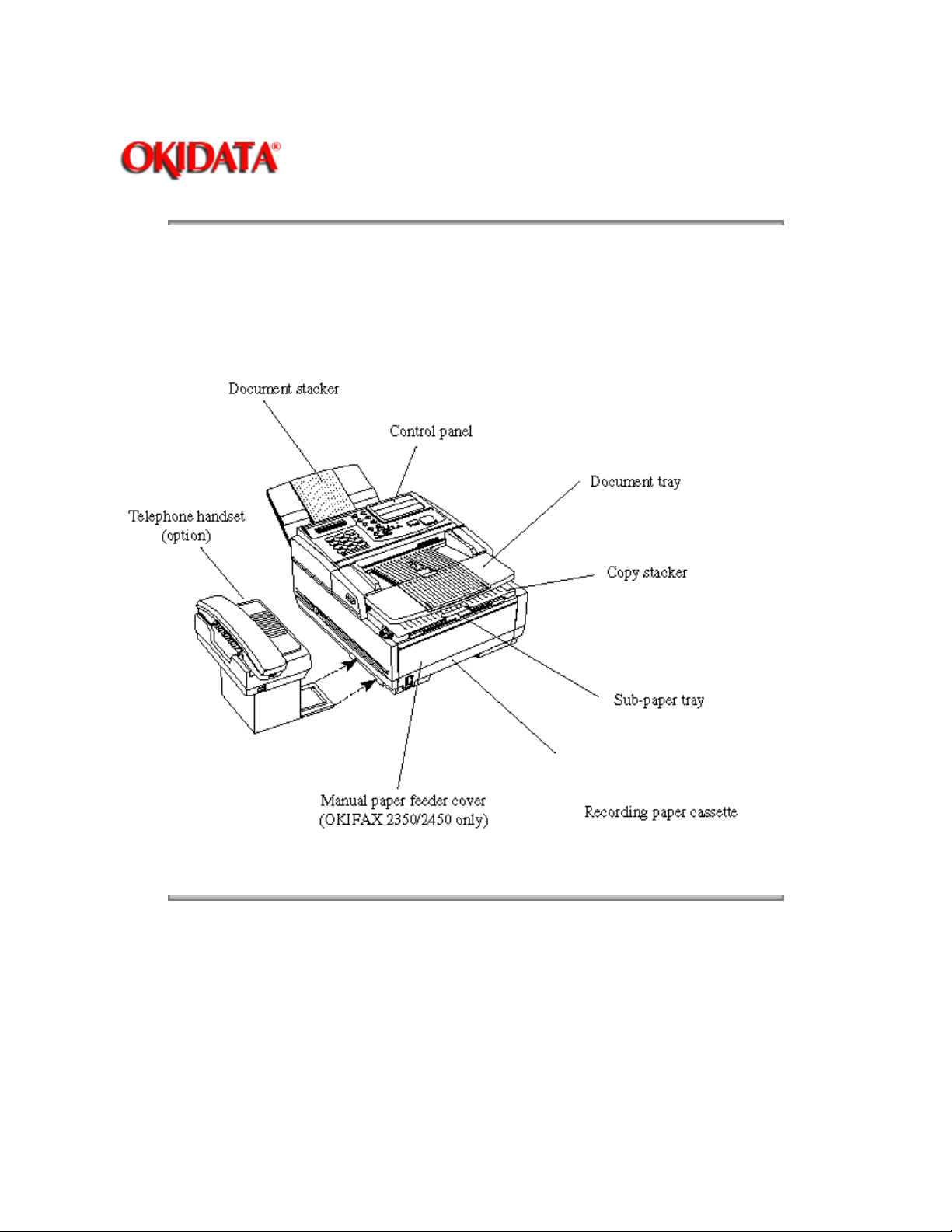
Figure 1.4.1 shows the general appearance of the OKIFAX 1050/2350/2450.
Figure 1.4.2 shows the control panel of the OKIFAX 1050.
Figure 1.4.3 shows the control panel of the OKIFAX 2350.
Figure 1.4.3 shows the control panel of the OKIFAX 2450.
Page: 10
Figure 1.4.1 General Appearance of OKIFAX 1050/2350/2450
Copyright 1997, Okidata, Division of OKI America, Inc. All rights reserved. See the OKIDATA Business
Partner Exchange (BPX) for any updates to this material. (http://bpx.okidata.com)
Page 23
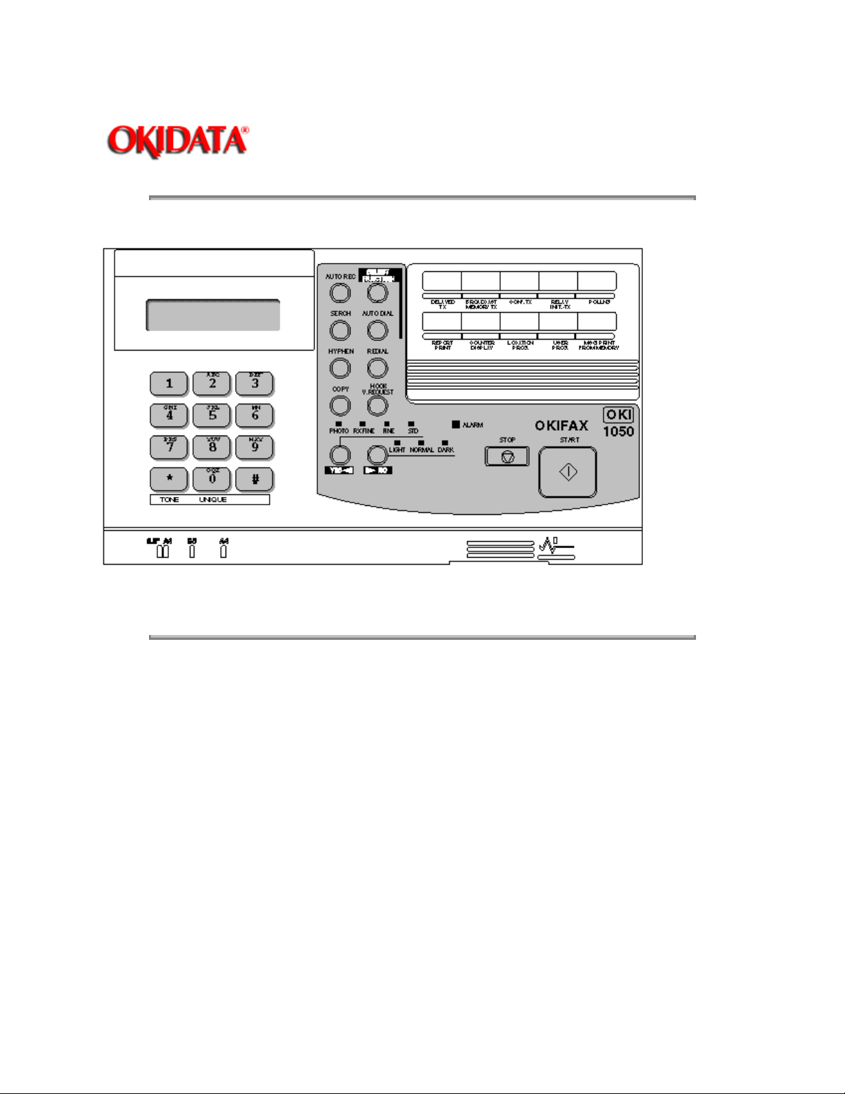
Figure 1.4.2 OKIFAX 1050 Control Panel
Page: 11
Service Guide OF1050/2350/2450
Chapter 1 General Information
Copyright 1997, Okidata, Division of OKI America, Inc. All rights reserved. See the OKIDATA Business
Partner Exchange (BPX) for any updates to this material. (http://bpx.okidata.com)
Page 24
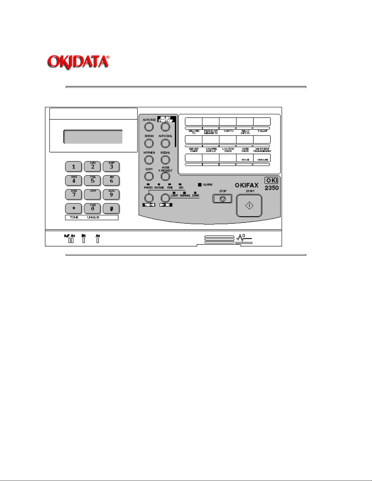
Figure 1.4.3 OKIFAX 2350 Control Panel
Page: 12
Service Guide OF1050/2350/2450
Chapter 1 General Information
Copyright 1997, Okidata, Division of OKI America, Inc. All rights reserved. See the OKIDATA Business
Partner Exchange (BPX) for any updates to this material. (http://bpx.okidata.com)
Page 25

Figure 1.4.4 OKIFAX 2450 Control Panel
Page: 13
Service Guide OF1050/2350/2450
Chapter 1 General Information
Copyright 1997, Okidata, Division of OKI America, Inc. All rights reserved. See the OKIDATA Business
Partner Exchange (BPX) for any updates to this material. (http://bpx.okidata.com)
Page 26

Page: 14
Service Guide OF1050/2350/2450
Chapter 1 General Information
1.5 Basic Performance Specifications
Table 1.5.1 shows basic performance specifications.
Note:
TF:
Technical function setting
FP:
Function program setting
OT:
One-touch key pressed
F:
SELECT FUNCTION key pressed
Table 1.5.1 (1/10) Basic Performance Specifications
No. No. Item Specifications
_________________________________________________________________________________
Applicable line 1) General switched telephone network (GSTN)
2) Private branch exchange (PBX) (OT9+2)
2 Line interface
1) Impedance 600W balanced
1
3 Type of document to be transmitted
1) Width Max. 8.5" (216 mm) (NA Letter)
mm).
2) Length Min. 5" (128 mm)
minutes
document scanning)
scanning feature on or off for each call in the
operating sequence.
3) Thickness Based on common bond paper,
4) Shape Rectangular
5) Opacity Documents allowing less than 40% of the
scanner source light to pass through them.
Min. 148 mm (ISO A5 size)
Note
: Effective reading width is NA Letter (215
Max. 14" (356 mm)
Long document detection: 14" (356 mm), or 60
*TF + 06 (To enable or disable the long
An operator can turn the long document
a) 0.08 to 0.13 mm for multiple page feeding
b) 0.06 to 0.15 mm for single page feeding
4 Effective reading width
Page 27

Document
width
Communication
Mode/Paper width
Effective reading
width
Copy size
ISO A4 (210 mm)
[INT'L/FTZ]
NA letter (216 mm)
[US/CANADA]
NA legal (216 mm)
[US/CANADA]
5 Automatic document feeder (ADF) Up to 11.7" (297 mm) in length. Max. 30
stacker. The first sheet will be fed first in the
6 Document skew Max. 2.6 mm skew over a document of 11.7"
11.7" (A4) length is 0.5% or less.
7 Document jam detection 1) Transmission will stop and line disconnection
detected within 14" (356 mm) after scanning
begins (except for the long document scanning. TF + 06)
G3/A4 8.2" (208 mm) A4
G3/A4 8.46" (215 mm) Letter
G3/A4 8.46" (215 mm) Legal
documents:
NA Letter or A4 (20-1b) Max. 15 documents:
NA Letter or A4 (13-28lb bond paper)
Documents shall be placed facedown on ADF
feeder and will exit facedown in the document
stacker.
(A4) length.
For a document longer than 11.7" (A4) length,
occurrence of skew exceeding 2.6 mm over any
will occur when the end of a document is not
2) A jam will also be declared if the document
does not reach the scanning position within 5.5
seconds (OKIFAX 2350/2450)/10 seconds
(OKIFAX1050) after the start of a document feed.
Note: When a jam is detected during message
transmission from the feeder, the machine will
stop scanning and disconnect the line, but its
receiving capability will remain valid.
8 Manual release
9 Recording paper or sheet For the first or second recording paper cassette:
1) Type: Plain paper cut (Bond paper)
2) Size: ISO A4 8.26" x 11.7" (210 mm x 297
mm)
NA Letter 8.5" x 11" (215.9 mm x 279.4 mm)
NA Legal 8.5" x 14" (215.9 mm x 355.6 mm)
3) Weight: 16 lbs to 24 lbs/base weight
Page 28
Base weight is defined as the weight of 500
sheets of 17" x 22" (431.8 mm x 558.8 mm).
4) Thickness: 0.08 mm to 0.12 mm
5) Condition: New paper
For the manual loading feeder on the OKIFAX
2350/2450
1) Type: Plain paper, transparency for overhead
projector, colored paper, printed paper
2) Size: A4/NA Letter/NA Legal
3) Weight, thickness and condition: Same as
above
Note: One single sheet only should be loaded
on the manual loading feeder at a time.
For best results use OKI DATA recommended
papers
1) Xerox 4200 (20 - lb/base weight paper)
10 Recording paper cassette
1) First cassette 250 sheets/cassette (Okidata recommended
2) Second cassette (Option) 500 sheets/cassette (Okidata recommended
(For OKIFAX 2350/2450) The fax can discharge printed copies and stack
11 Effective recording area
2) L-type paper for photo-printers
paper)
paper)
them facedown.
Maximum sheets on the copy stacker: 100*
Note: These tables do not include
vertical and horizontal addressing
Page 29
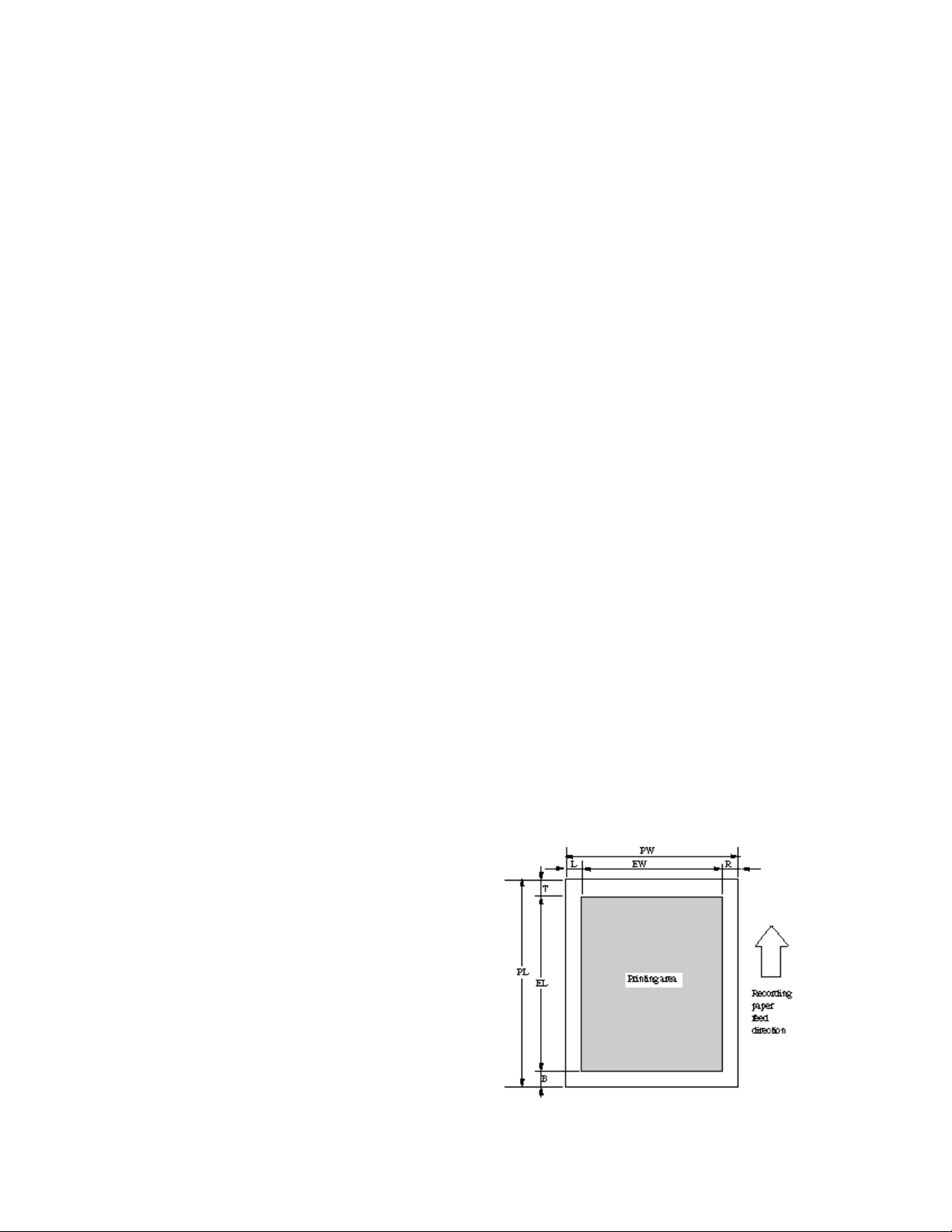
deviations (+ or 2 mm) of recording
paper.feed direction
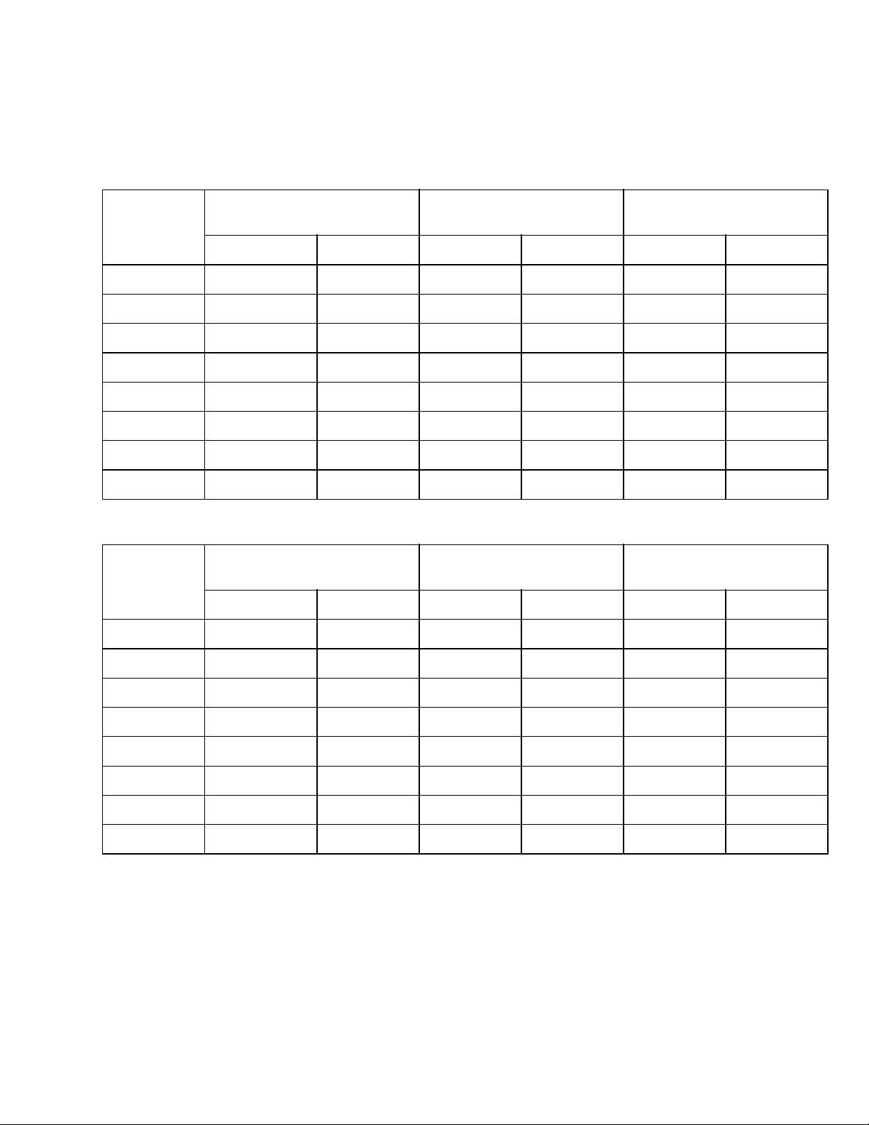
1) Printable area
NA LETTERSIZEISO A4 SIZE NA LEGAL SIZE
inch mm inch mm inch mm
PL 11 279.4 11.7 297 14 355.6
PW 8.5 215.9 8.3 210 8.5 215.9
EL 10.76 273.3 11.46 291 13.76 349.5
EW 8.18 208 8.11 206 8.18 208
T 0.12 3 0.12 3 0.12 3
B 0.12 3 0.12 3 0.12 3
L 0.16 3.95 0.09 2 0.16 3.95
R 0.16 3.95 0.09 2 0.16 3.95
NA LETTERSIZEISO A4 SIZE NA LEGAL SIZE
inch mm inch mm inch mm
PL 11 279.4 11.7 297 14 355.6
PW 8.5 215.9 8.3 210 8.5 215.9
EL 10.5 266.7 11.19 284.3 13.5 342.9
EW 8 203.2 7.77 197.3 8 203.2
T 0.25 6.35 0.25 6.35 0.25 6.35
B 0.25 6.35 0.25 6.35 0.25 6.35
L 0.25 6.35 0.25 6.35 0.25 6.35
R 0.25 6.35 0.25 6.35 0.25 6.35
12 Copy stacking * Okidata recommended paper (20lb)
13 Scanning resolution Horizontal: 8 pel/mm
Vertical:
Transmission mode: 3.85 line/mm (STD),
7.7 line/mm (FINE) or
15.4 line/mm (EX. FINE)
Copy mode: 7.7 line/mm
Page 30

14 Image scanning method NA Letter size (1728-bit) contact image sensor
15 Contrast control 1) Automatic background sensing
A continuous document background of 0.3 OD
(optical density) or less will be transmitted as
white.
2) The LIGHT and DARK contrasts will
automatically be adjusted to improve image
quality.
16 Recording resolution Horizontal: 8 dot/mm
Vertical:
Fixed: 3.85 line/mm (200 x 100 LPI) (STD)
7.7 line/mm (200 x 200 LPI) (FINE, COPY)
17 Recording system Electro-photographic printing
A4 size (1728-bit) LED print head
18 Skew of recording paper Maximum allowable skew is + or - 1 mm over an
advance of 3.93" (100 mm.)
19 Copy darkness 1) Black image: Greater than 1.0 OD
(Optical density)
2) White background: Not greater than 0.2
OD (Optical density)
20 Copy uniformity Printed copies will exhibit a uniform density of
the printed and background area:
1) From edge to edge: 25% unit
2) From copy to the next copy: 30% unit
21 Recording paper running out The fax can detect the no-paper condition by a
photosensor.
When the paper has run out in the local copy
operation, the scanning will stop with "NO
PAPER ... REPLACE PAPER" on the LCD, and
an ALARM LED turns on without an alarm tone.
When the paper has run out while a message is
being received and the no-paper reception is
activated, the LCD display will show "MSG. IN
MEMORY", and the ALARM LED turns on.
22 Minimum scan line time 0 ms, when receiving from an OKIDATA for
receiving facsimile.
5 ms at 7.7 line/mm and 10 ms at 3.85 line/mm
when receiving from a non-OKIDATA facsimile.
23 Coding scheme 1) One-dimensional coding scheme:
Modified Huffman (MH)
2) Two-dimensional coding scheme:
Modified READ (MR)
Page 31

Modified modified READ (MMR)
24 MODEM
1) High-speed MODEM a) ITU-T Rec. V.29 (9600/7200 bps)
b) ITU-T Rec. V.27 ter (4800/2400 bps)
c) ITU-T Rec. V.17 (14400/12000/9600/7200
bps); OKIFAX 2450, OKIFAX 2350 (option)
d) ITU-T Rec. V.33 (14400/12000 bps); OKIFAX
2450, OKIFAX 2350 (option)
2) Low-speed MODEM ITU-T Rec. V.21 channel 2 (300 bps)
25 Fallback Automatic fallback will occur according to the
following sequence by FTT, RTN or PPR.
Fallback
rank
1st 14400 bps 1 1 4 (Note 1) ITU-T V.17
2nd 12000 bps 1 1 4 (Note 1) ITU-T V.17
3rd 9600 bps 1 1 4 (Note 1) ITU-T V.17
4th 7200 bps 1 1 4 (Note 1) ITU-T V.17
5th 4800 bps 2 1 4 (Note 1) ITU-T V.27 ter.
6th 2400 bps 2 1 4 (Note 1) ITU-T V.27 ter.
Transmissio
n
speed
disconnection.
Activated
by FTT
(Times)
sends out a DCN signal to the remote station for
page within each fallback rank.
Activated by
RTN (Times)
When the last trial fails, the transmitting station
Note 1: Continuous PPRs for the same partial
Activated by
PPR (Times)
Protocol
(V.33)
(V.33)
(V.29)
(V.29)
26 Protocol 1) ITU-T Rec. T.30
2) OKIDATA special protocol high-speed
protocol
The T.30 protocol signal from the transmitting
station is sent at message transmission speed
instead of 300 bps.
Note: In high-speed protocol, 14.4 and 12 K-bps
are not applied.
27 Transmission time 6 sec./ITU-T No. 1 sample document (OKIFAX
2350/2450, option)
Page 32
9 sec./ITU-T No. 1 sample document (OKIFAX
1050/2350)
Note: This is Phase C time at 3.85 line/mm and
14400 bps for 6 sec. and 9600 bps for 9 sec. in
MMR code transmission.
28 Error correction ITU-T Error correction mode (ECM)
OKIDATA ITU-T ECM
29 Communication mode Half-duplex
30 Ringing signal detection sensitivity
1) Voltage range 25 to 150 V r.m.s.
Inoperative below 10 V
2) Frequency range 20 to 68 Hz
3) Ring response time One-ringing signal or 5 to 30 seconds.
(Selectable in 5 sec. steps. F + OT9 + ¬ + 15)
31 Image memory
Basic model Optional memory
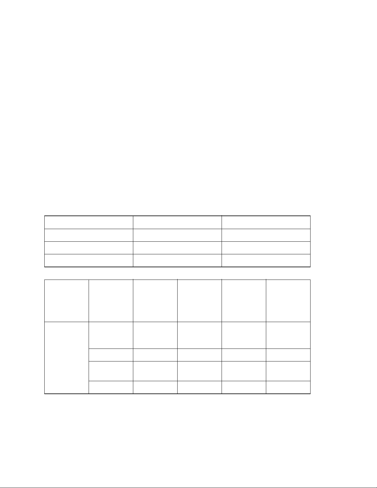
OKIFAX 1050 256K-byte 512K-byte/1M-byte
OKIFAX 2350 256K-byte 512K-byte/1M-byte/2M-byte
OKIFAX 2450 OKIFAX 2450 512K-byte 512K-byte/1M-byte/2M-byte
Memory
condition
With Standard
(without
option)
option 0.5M-byte 56 56 79 70
1M-byte 100 100 120 110
board 2M-byte 180 200 195
OKIFAX
1050
[pages]
17 17 35 27
ITU-T No.1 sample documents are used.
OKIFAX
2350
[pages]
Note: No. of sheets is counted provided that
OKIFAX
2450
A4 Setting
[pages]
OKIFAX
2450
LEGAL
Setting
[pages]
Note: Back-up time on electrical interruption:
Min. one hour (OKIFAX 2450 only)
Page 33

Note: OKIFAX 1050/2350 does not back up the
message received in memory for the power
failure.
32 Telephone handset General telephone function is available while the (option)
power is on.
34 Overheat protection The heat of the fuser unit is controlled within
predetermined temperature range by the
thermistor. If the temperature of the
heater exceeds this range, the LCD displays
"PRINTER ALARM 4".
Furthermore, the built-in thermostat in the fuser
unit prevents the fuser from being overheated
even in the event of the failures in the above
temperature control circuit.
35 PC interface applications (Option) The following four modes are supported:
(Applies to EIA class 1) 1) PC local printer mode
2) PC scanner mode
3) PC transmission mode
4) PC reception mode
36 Power supply unit and power
consumption of the machine
Nominal input
voltage
Input voltage range
Frequency range
Power consumption of the
machine (Typical power)
1) Transmit
2) Receive (*)
3) Local copy(*)
4) Standby
* Chart: ITU-T No. 1 sample document
37 Ambient condition
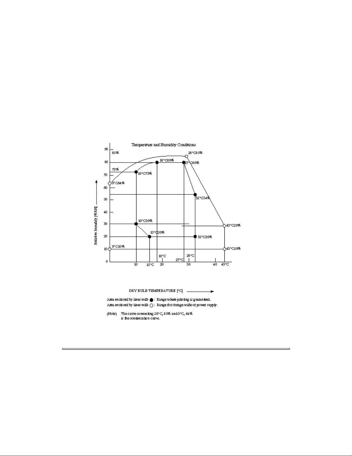
1) Operating condition See Figure 1.5.1
2) Storage condition See Figure 1.5.1
38 Dimension 1) Width: Approx. 13" (330 mm)
(Main body) 2) Depth: Approx. 16.5" (420 mm)
39 Weight Approx. 26.66 lbs (13 kg)
120 VAC
102 to 127 VAC
50/60 Hz ± 2%
FX-050
22 W
183 W
208 W
9 W
FX-175
25 W
227 W
330 W
12.1 W
3) Height: Approx. 9.25" (235 mm)
Page 34
(Main body) Excluding optional units, recording paper and
packing materials.
40 Attachment 1) AC power cord x 1
(to the main body) 2) Image Drum unit x 1 (Already installed)
3) Toner cartridge x 1
4) Telephone handset x 1 (option)
5) Curled cord and Telephone cord for (#4) x 1
(option)
6) Document stacker x 1
7) Telephone Line cord x 1
8) One touch sheet x 1 (Already installed)
9) User's guide x 1
Temperature and Humidity Conditions
Figure 1.5.1 Ambient Condition
Copyright 1997, Okidata, Division of OKI America, Inc. All rights reserved. See the OKIDATA Business
Partner Exchange (BPX) for any updates to this material. (http://bpx.okidata.com)
Page 35
Service Guide OF1050/2350/2450
1.6 Reports and Lists
Table 1.6.1 (1/23) Reports and Lists Specifications
Table 1.6.1 shows Reports and Lists Specifications.
Page: 15
Chapter 1 General Information
Note
No. Item Specifications
______________________________________________________________________
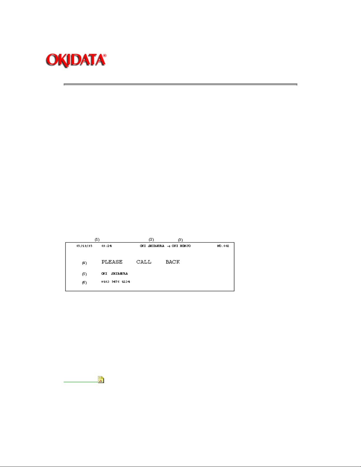
1 Call-back message The transmitter sends a call-back message to
F +OT:
:
FP:
TF:
Press FUNCTION and One-touch key
Function program setting
Technical function setting
respond to voice request of the transmitter
function.
Call-back Message Format: (Example)
the receiver only when the receiver does not
(Feeder Transmit only)
Note :
Number must be programmed to enable this
Sender Id plus Call Back Telephone
2 Sender ID* (1) Date and time
Fax machines use this information (2) Sender ID
to identify themselves during (3) CSI/Personal ID
communications. In the United (4) Letters PLEASE CALL BACK
States and most other countries, (5) Sender ID
programming this information into (6) Senders call back telephone number
your fax machine is a legal
requirement (for more information, The fax can transmit a programmed refer to
the "Federal Communica- alphanumeric message, such as
tions Commission Requirements company's name, consisting of up to 32 for End
Users" at the beginning of characters.
this manual.
* (Outside only)
Sender ID Format: (Example)
Page 36
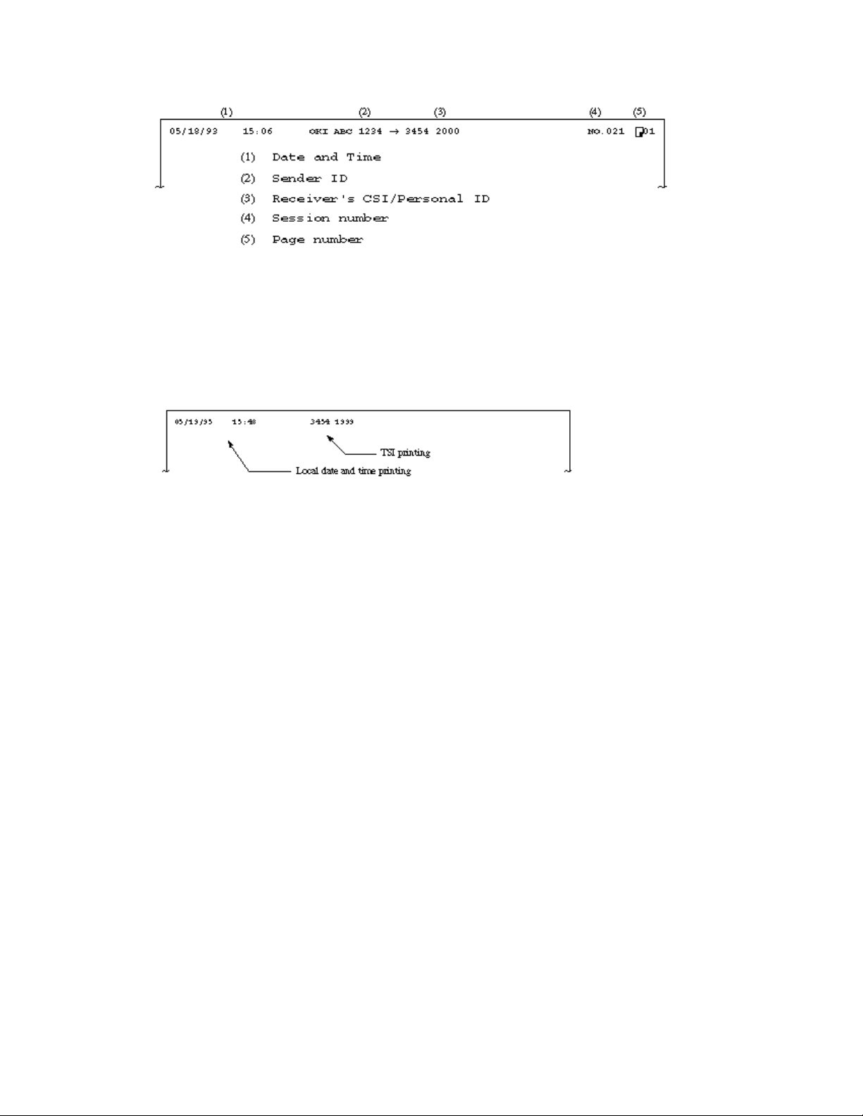
3 Transmitting subscriber
identification (TSI printing Received TSI can be printed at the top of the
received page.
* TF + 10 (To enable or disable this function)
* TF + 09 Local date and time printing
(OFF/ONCE/ALL pages)
TSI Printing and Local Date and Time Printing Format: (Example)
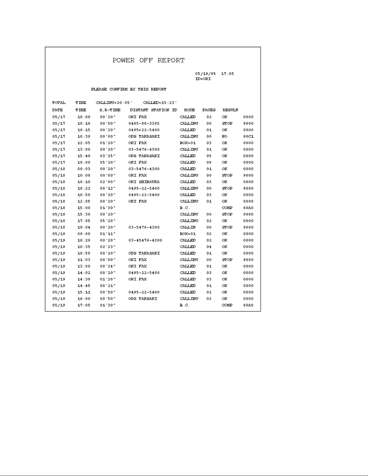
4 Cancel report The fax can automatically print out a power-off
report when the power off condition occurs.
(Power off report)
Cancel Report Format: (Example)
Page 37
5 Activity report The fax can print out an activity report manually,
or automatically when 30 communications are
recorded.
* REPORT PRINTOUT+1(Manual printout)
* TF + 34 (Automatic printout, Default is OFF)
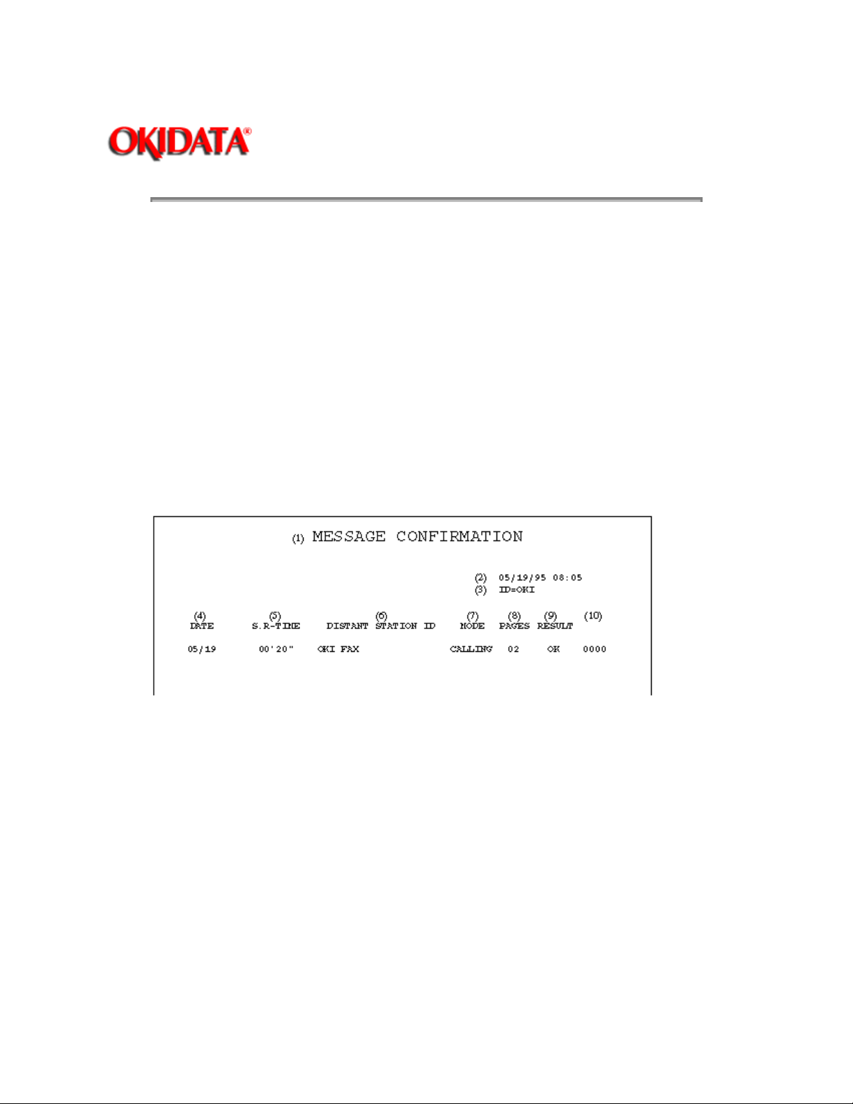
Message Confirmation Report Format: (Example)
Page 38
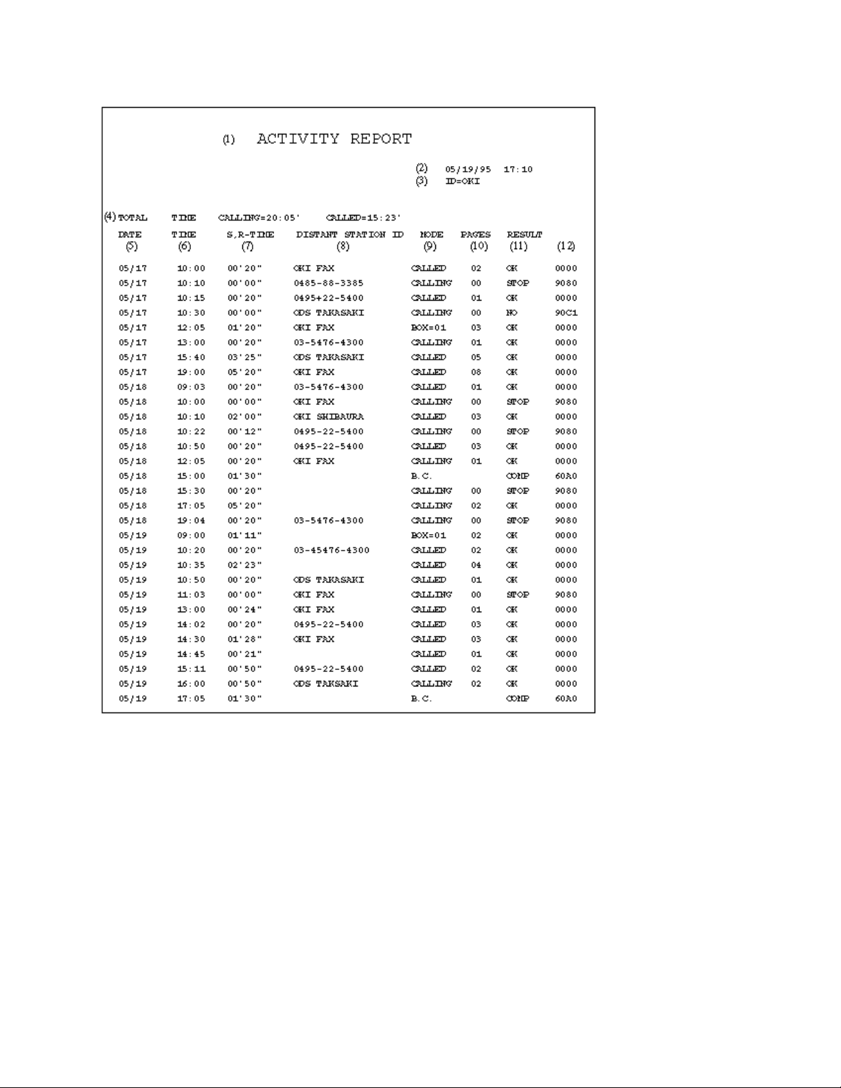
(1) Title of the report
(2) Date and time when the report was printed
(3) Sender ID
(4) Total TX and RX time
(5) Date of transmission or reception
(6) Time when the communication started
(7) Time span of the fax communication.
(8) Identification of the remote station
Personal ID/Location ID/TSI/CSI/Dial number or space
(9) Communication mode:
CALLING (Transmission)
CALLED (Reception NG or MEMORY RX)
B. C. (Broadcast)
BOX=XX (Confidential reception)
(10) Number of transmitted pages or received pages
Page 39

(11) Result code
OK (Note1)/NO/STOP (Note 2)/BUSY/PAPER (Out of recording
paper)/S_JAM (Document
jam)/R_JAM (Recording paper jam)/COVER/COMP (Completion of a
broadcast)/PUNIT
(Printer Alarm)/CANCL (Confidential reception T.O.)
Note 1 The following cases are included:
Unmatched handshaking to the received NSF.
Unmatched password to the received NSC in the polling transmission
mode.
Note 2: The following cases are included:
The STOP key is pressed.
The memory cancellation operation removes the message from the
active memory files.
(12) Service code
Copyright 1997, Okidata, Division of OKI America, Inc. All rights reserved. See the OKIDATA Business
Partner Exchange (BPX) for any updates to this material. (http://bpx.okidata.com)
Page 40
Service Guide OF1050/2350/2450
Chapter 1 General Information
No. Item Specifications
6 Message confirmation report The fax can print out a message confirmation
report manually or automatically depending on
user set-up.
Note
1: When COPY key is pressed
immediately after a single location
transmission, this report can be printed (Manual
printout)
Page: 16
memory.
Note 2:
document will be printed just below the
message confirmation when sending from
Message Confirmation Report Format (1/2): (Example)
Message Confirmation Report Format (2/2): (Example)
A portion of the first page of the TX
Page 41
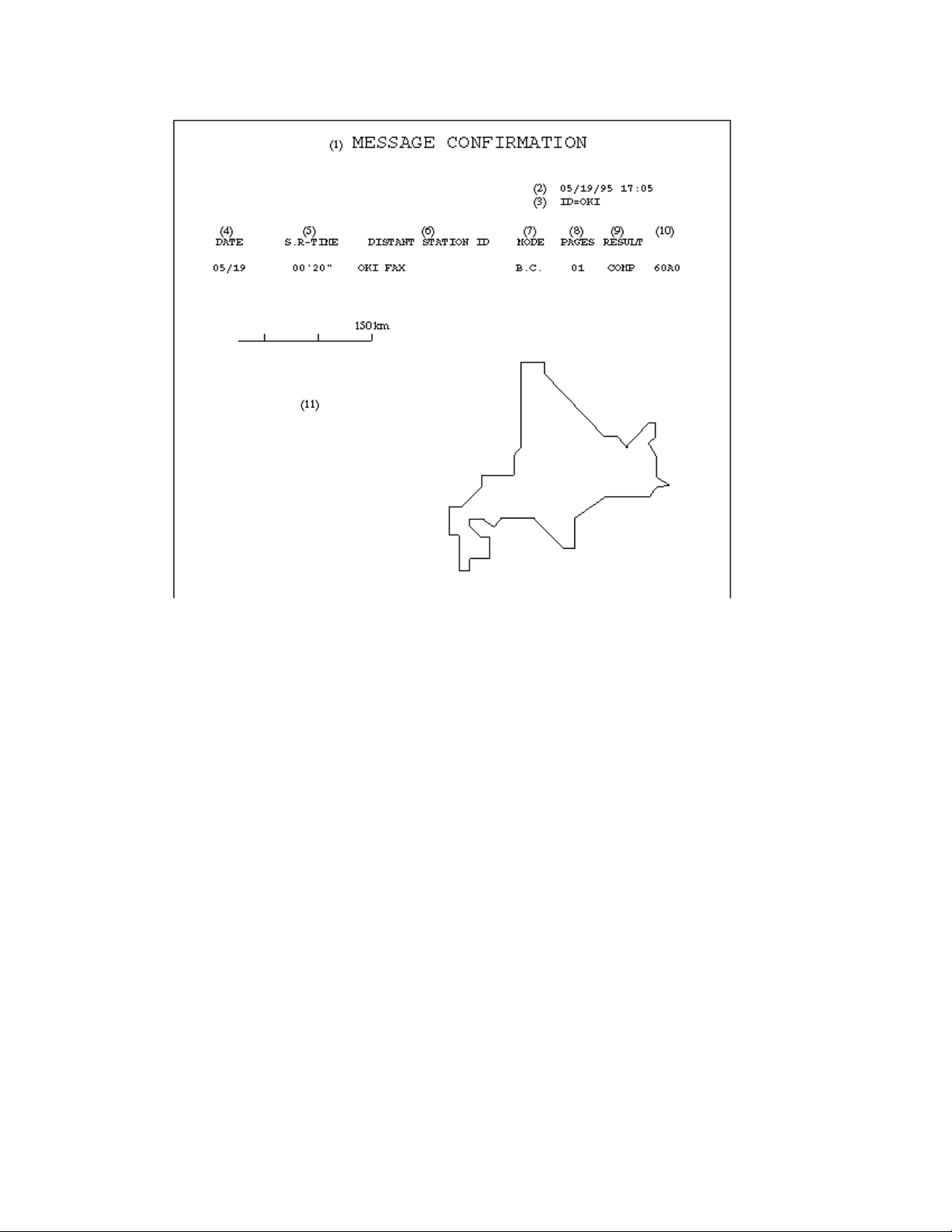
(1) Title of the report
(2) Date and time when the report was printed
(3) Sender ID
(4) Date of transmission or reception
(5) Length of time for which the fax was connected to the line
(6) Identification of the remote station
Personal ID/Location ID/TSI/CSI/Dial number
(7) Communication mode
Reference to ACTIVITY REPORT
(8) Number of transmitted pages or received pages
(9) Result of the communication
Reference to ACTIVITY REPORT
(10) Service code
(11) Portion of the first page transmitted
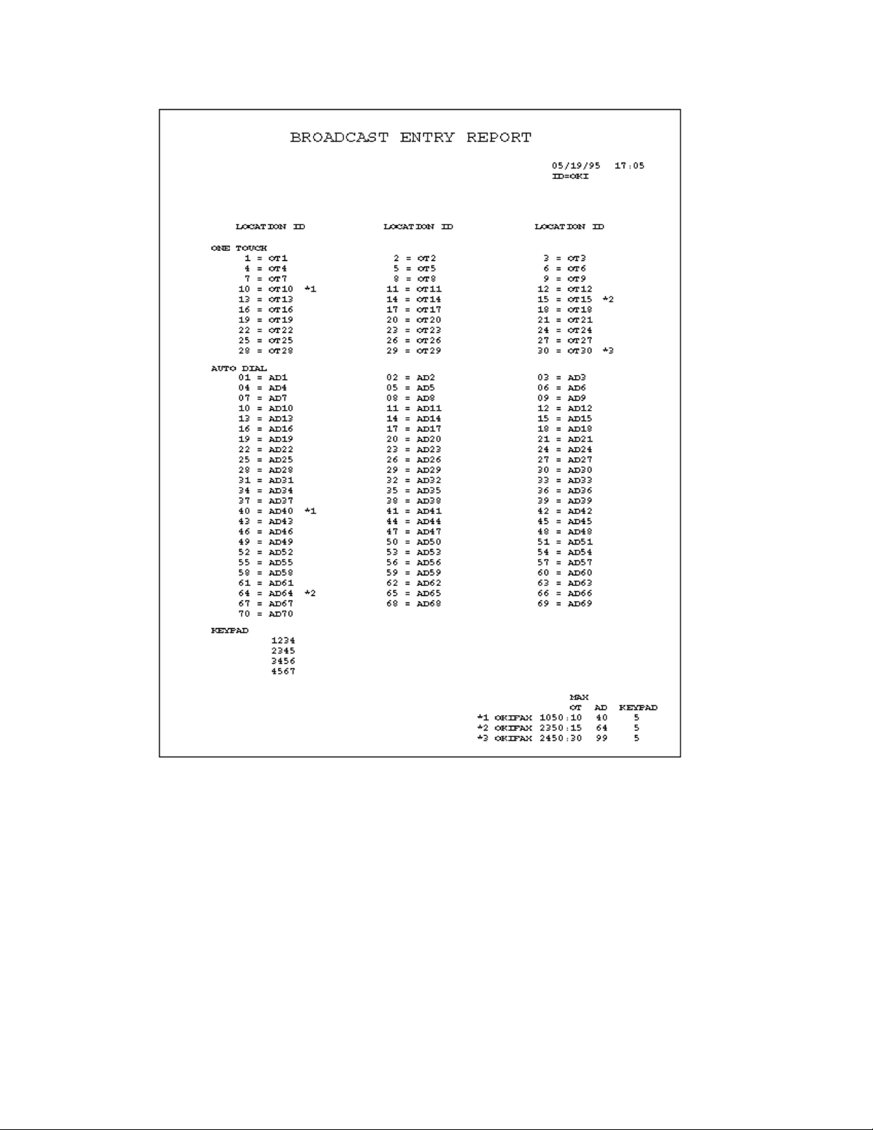
7 Broadcast entry report The fax can print out a broadcast entry report if
specified during programming sequence of a
broadcast.
Broadcast Entry Report Format: (Example)
Page 42
8 Broadcast confirmation report The fax can print out a broadcast confirmation
report manually or automatically, depending on
user set-up.
* COPY key (Manual printout): Pressed
immediately after a broadcast, will enable the
manual printing of a broadcast confirmation
report.
+ REPORT PRINTOUT + 2 (Manual printout)
* FP +02 (To enable or disable automatic
printing)
Broadcast Confirmation Report Format: (Example)
Page 43
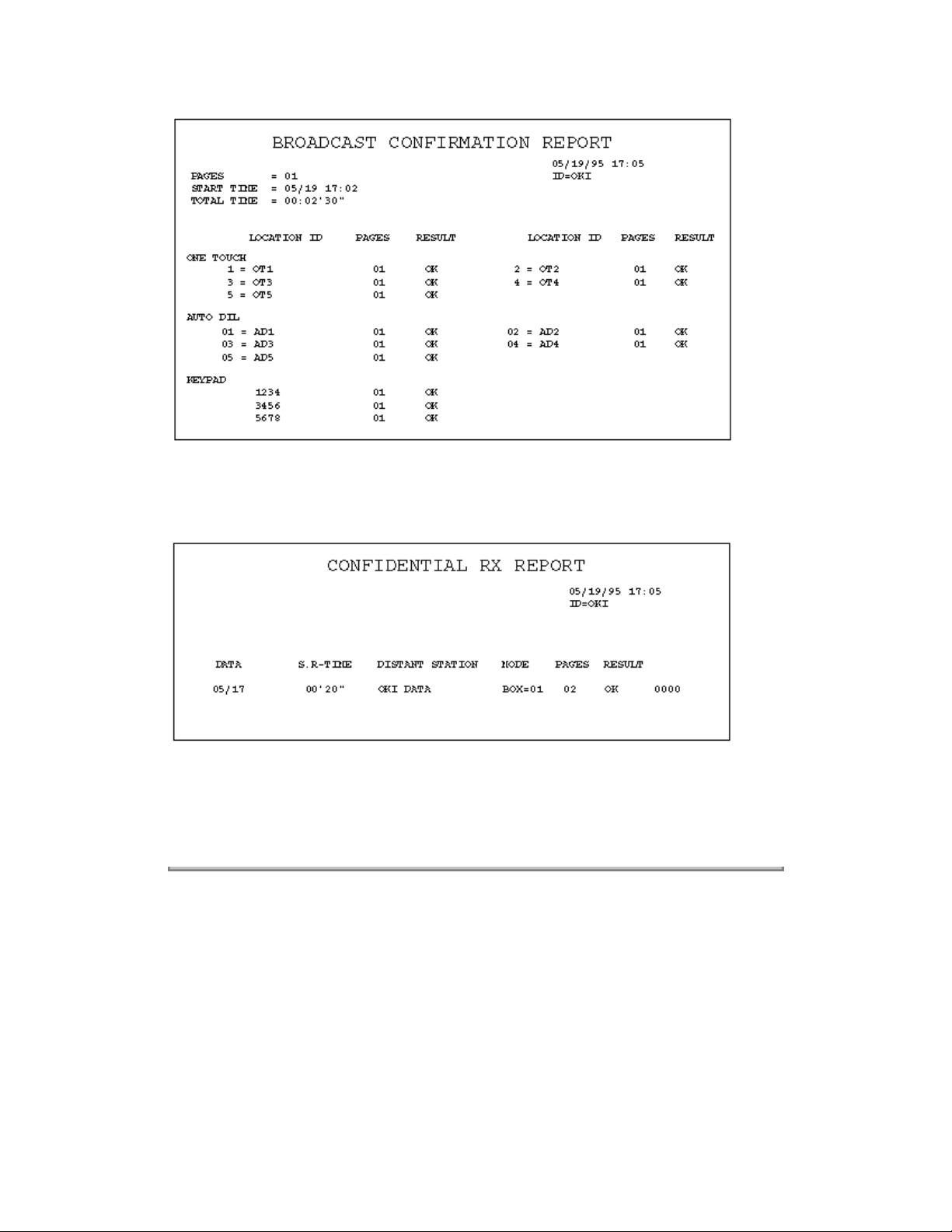
9 Confidential reception report The fax can print out this report automatically on
completion of a confidential reception.
Confidential Reception Report Format: (Example)
10 Telephone directory This directory is printed manually.
(REPORT PRINTING +3)
See following sections for examples.
Copyright 1997, Okidata, Division of OKI America, Inc. All rights reserved. See the OKIDATA Business
Partner Exchange (BPX) for any updates to this material. (http://bpx.okidata.com)
Page 44
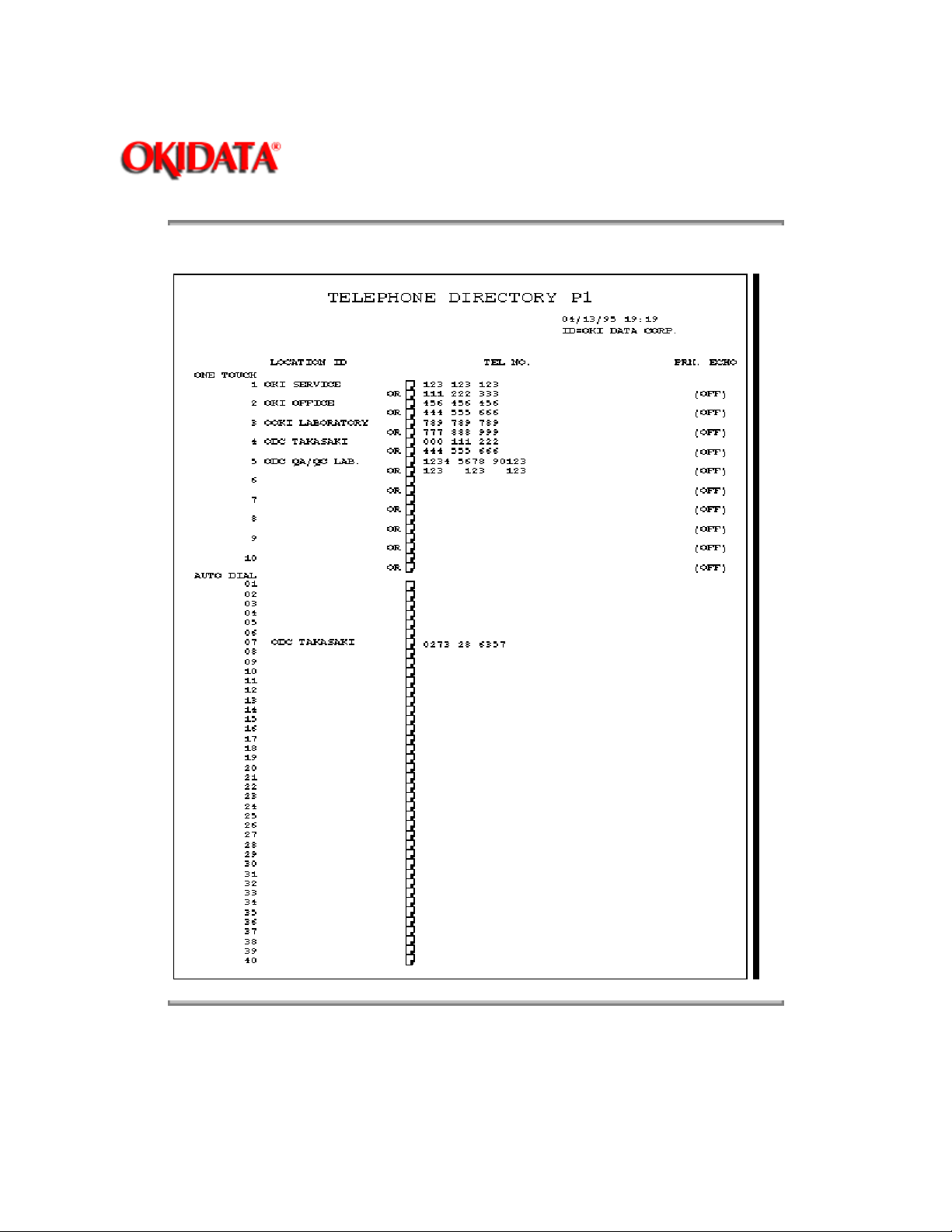
Service Guide OF1050/2350/2450
Chapter 1 General Information
Telephone Directory for OKIFAX 1050 (1/2): (Example)
Page: 17
Copyright 1997, Okidata, Division of OKI America, Inc. All rights reserved. See the OKIDATA Business
Partner Exchange (BPX) for any updates to this material. (http://bpx.okidata.com)
Page 45
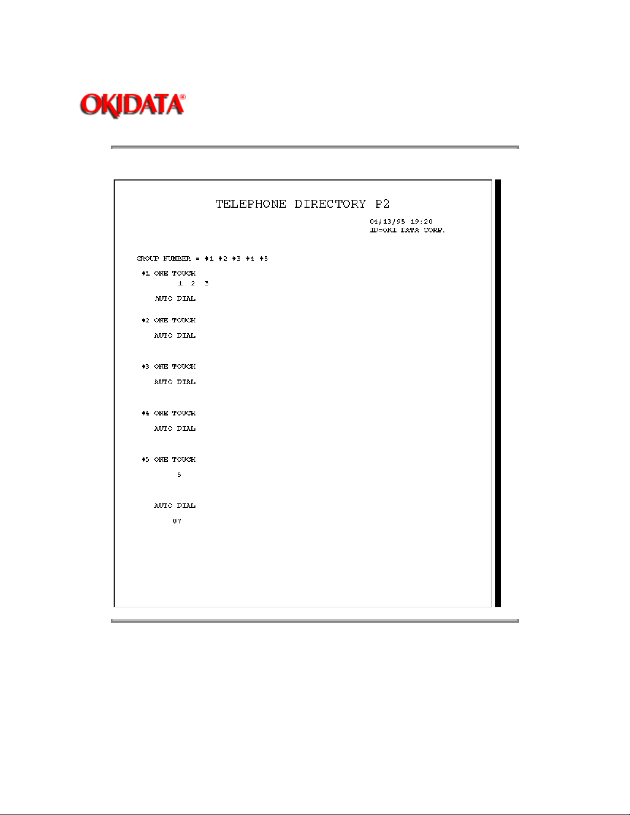
Service Guide OF1050/2350/2450
Chapter 1 General Information
Telephone Directory for OKIFAX 1050 (2/2): (Example)
Page: 18
Copyright 1997, Okidata, Division of OKI America, Inc. All rights reserved. See the OKIDATA Business
Partner Exchange (BPX) for any updates to this material. (http://bpx.okidata.com)
Page 46
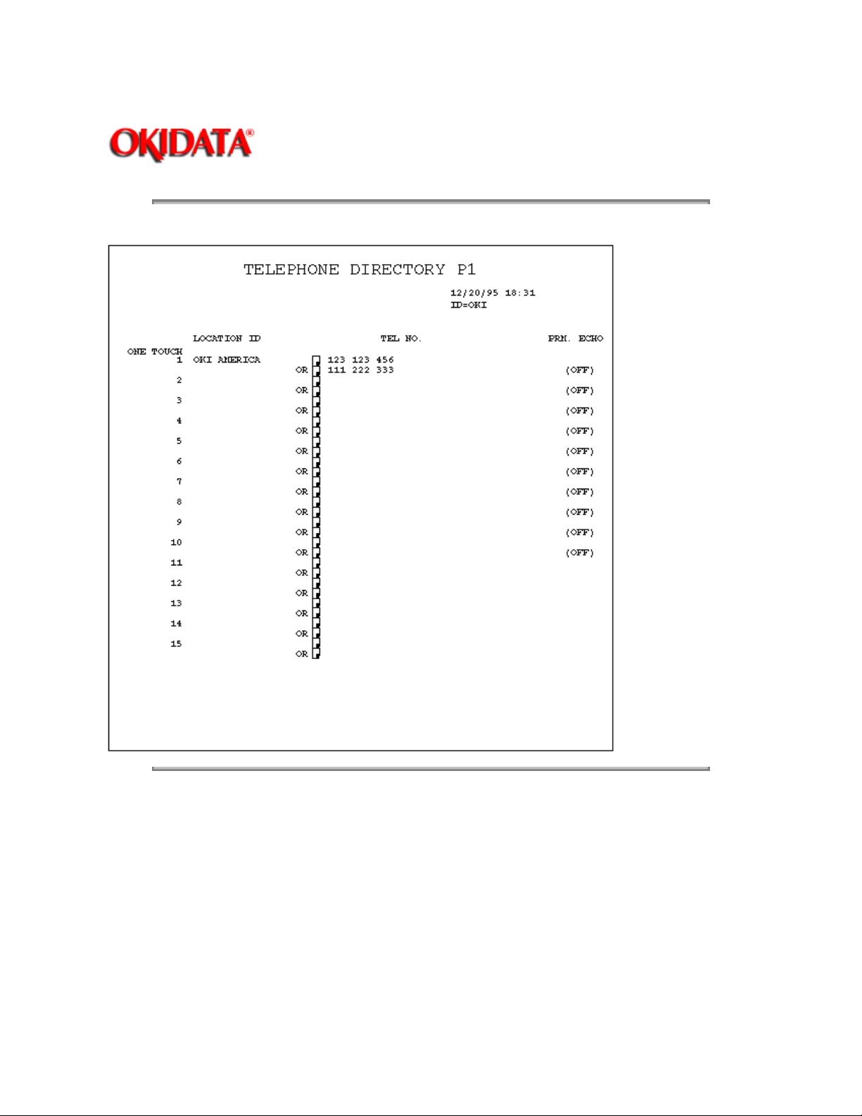
Service Guide OF1050/2350/2450
Chapter 1 General Information
Telephone Directory for OKIFAX 2350 (1/4): (Example)
Page: 19
Copyright 1997, Okidata, Division of OKI America, Inc. All rights reserved. See the OKIDATA Business
Partner Exchange (BPX) for any updates to this material. (http://bpx.okidata.com)
Page 47
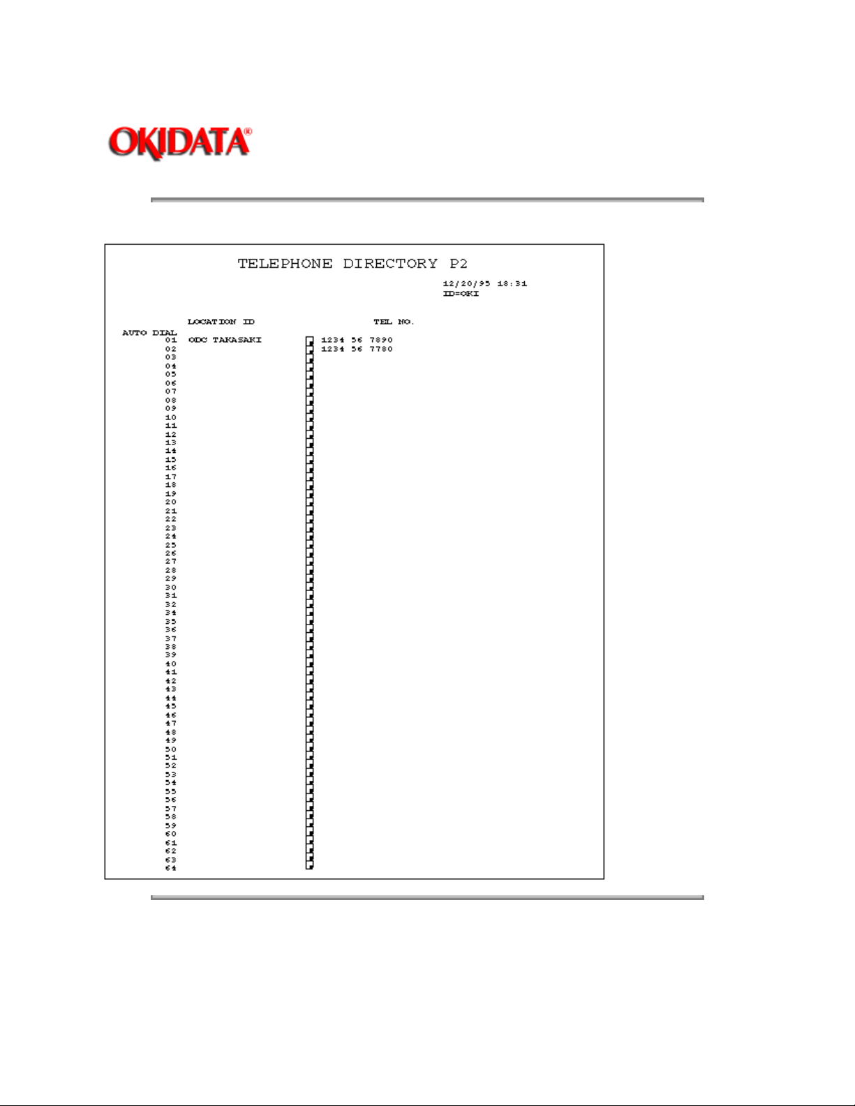
Service Guide OF1050/2350/2450
Chapter 1 General Information
Telephone Directory for OKIFAX 2350 (2/4): (Example)
Page: 20
Copyright 1997, Okidata, Division of OKI America, Inc. All rights reserved. See the OKIDATA Business
Partner Exchange (BPX) for any updates to this material. (http://bpx.okidata.com)
Page 48
Service Guide OF1050/2350/2450
Chapter 1 General Information
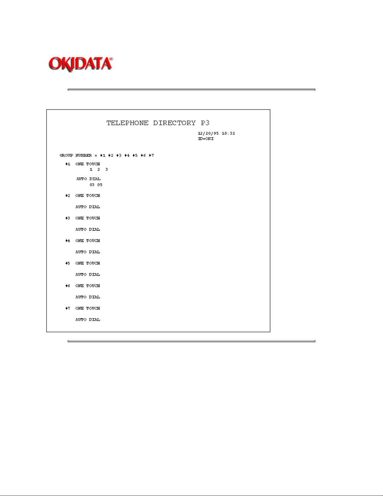
Telephone Directory for OKIFAX 2350 (3/4): (Example)
Page: 21
Copyright 1997, Okidata, Division of OKI America, Inc. All rights reserved. See the OKIDATA Business
Partner Exchange (BPX) for any updates to this material. (http://bpx.okidata.com)
Page 49
Service Guide OF1050/2350/2450
Chapter 1 General Information
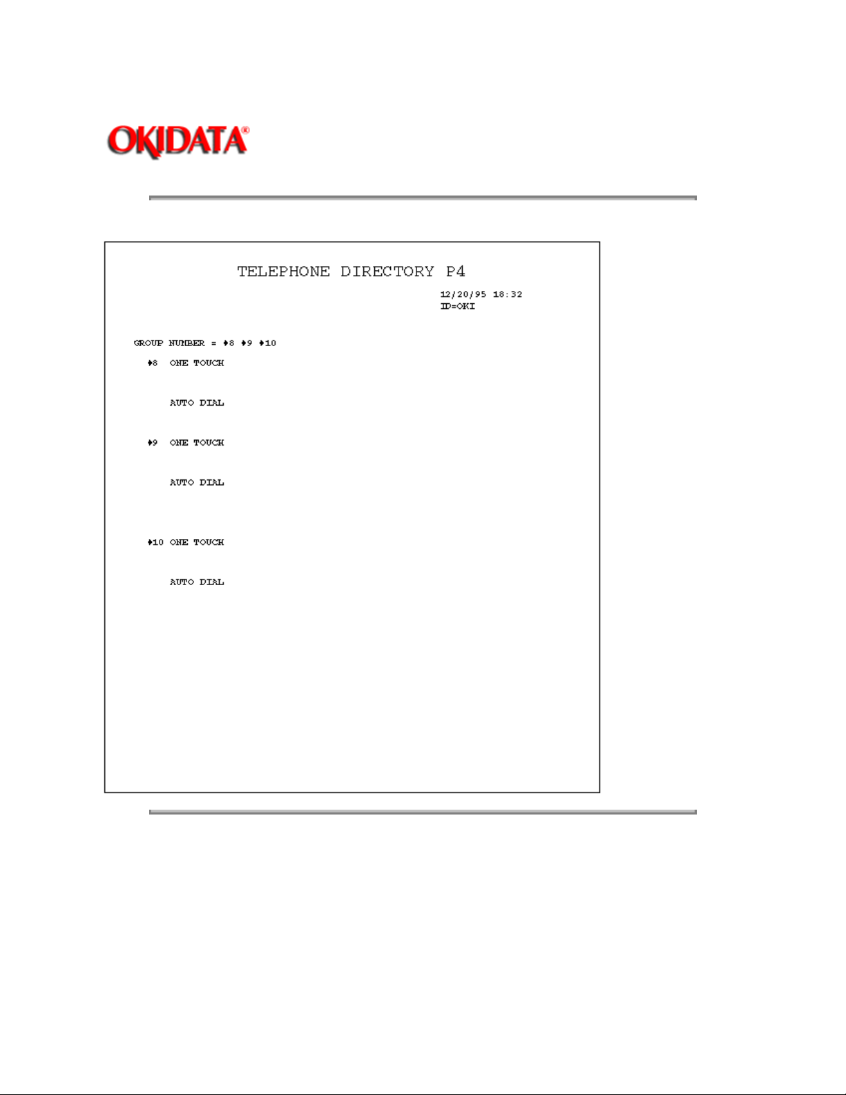
Telephone Directory for OKIFAX 2350 (4/4): (Example)
Page: 22
Copyright 1997, Okidata, Division of OKI America, Inc. All rights reserved. See the OKIDATA Business
Partner Exchange (BPX) for any updates to this material. (http://bpx.okidata.com)
Page 50
Service Guide OF1050/2350/2450
Chapter 1 General Information
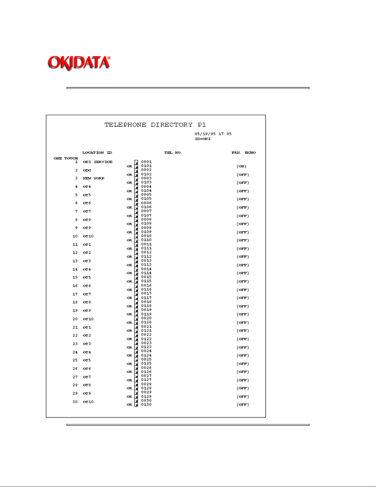
Telephone Directory for OKIFAX 2450 (1/6): (Example)
Page: 23
Copyright 1997, Okidata, Division of OKI America, Inc. All rights reserved. See the OKIDATA Business
Page 51

Partner Exchange (BPX) for any updates to this material. (http://bpx.okidata.com)
Page 52
Service Guide OF1050/2350/2450
Chapter 1 General Information
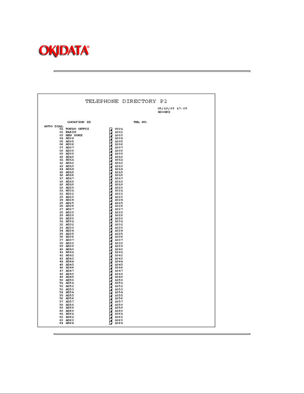
Telephone Directory for OKIFAX 2450 (2/6): (Example)
Page: 24
Copyright 1997, Okidata, Division of OKI America, Inc. All rights reserved. See the OKIDATA Business
Partner Exchange (BPX) for any updates to this material. (http://bpx.okidata.com)
Page 53
Service Guide OF1050/2350/2450
Chapter 1 General Information
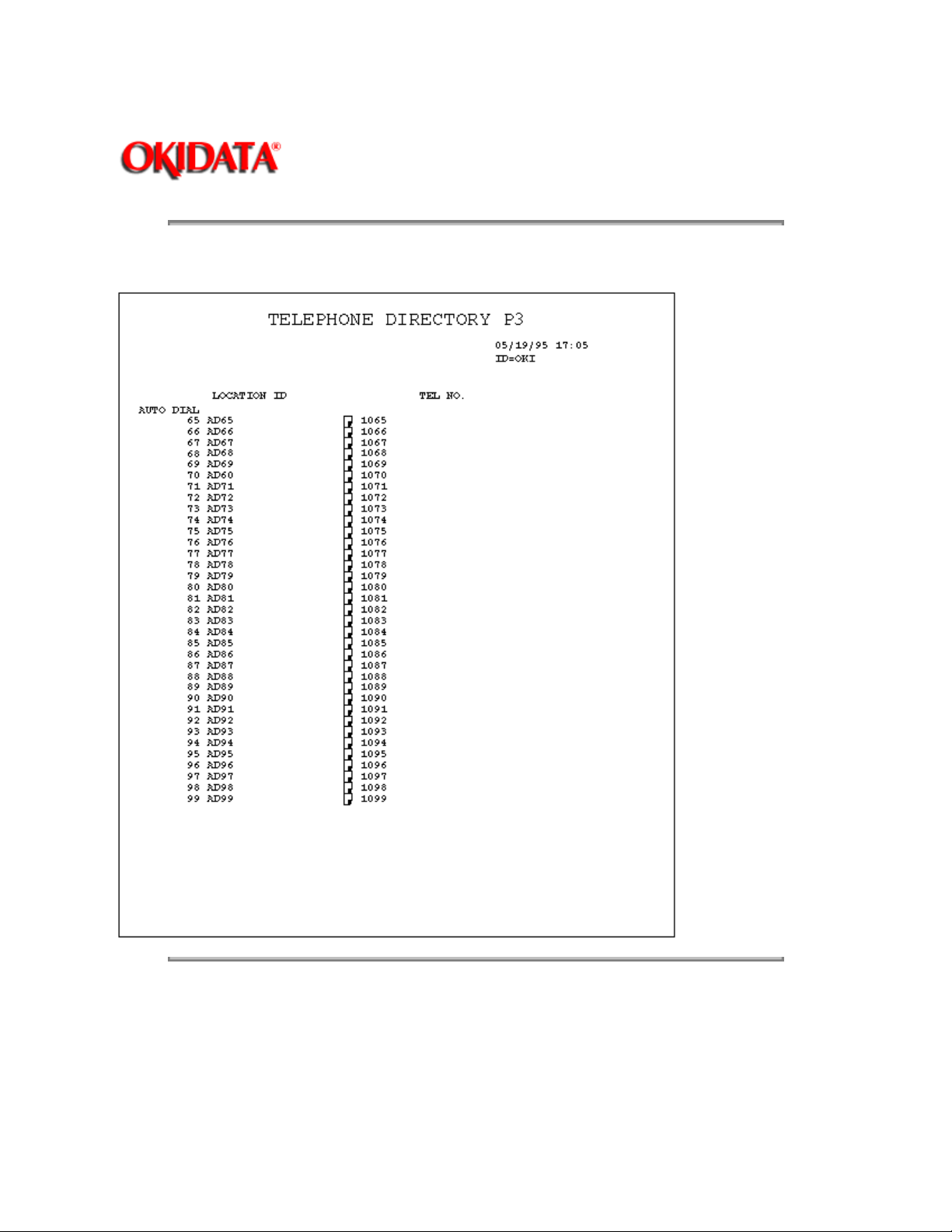
Telephone Directory for OKIFAX 2450 (3/6): (Example)
Page: 25
Copyright 1997, Okidata, Division of OKI America, Inc. All rights reserved. See the OKIDATA Business
Partner Exchange (BPX) for any updates to this material. (http://bpx.okidata.com)
Page 54
Service Guide OF1050/2350/2450
Chapter 1 General Information
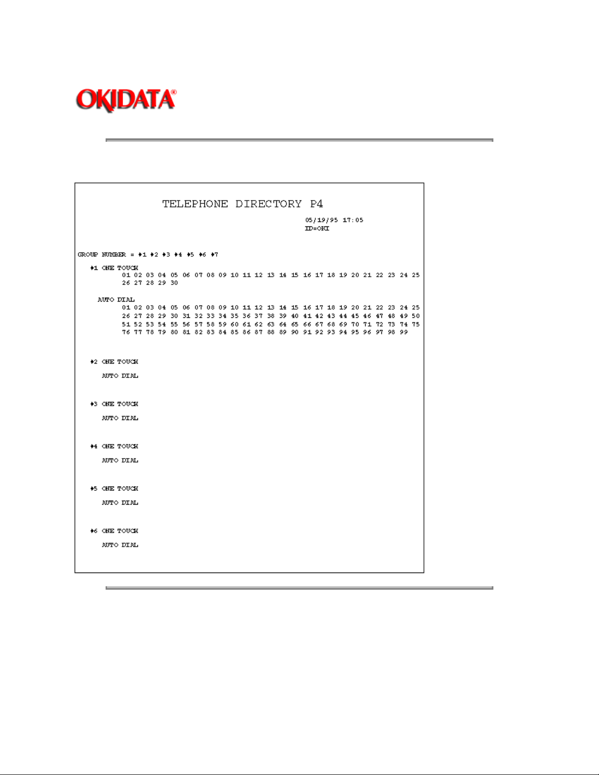
Telephone Directory for OKIFAX 2450 (4/6): (Example)
Page: 26
Copyright 1997, Okidata, Division of OKI America, Inc. All rights reserved. See the OKIDATA Business
Partner Exchange (BPX) for any updates to this material. (http://bpx.okidata.com)
Page 55
Service Guide OF1050/2350/2450
Chapter 1 General Information
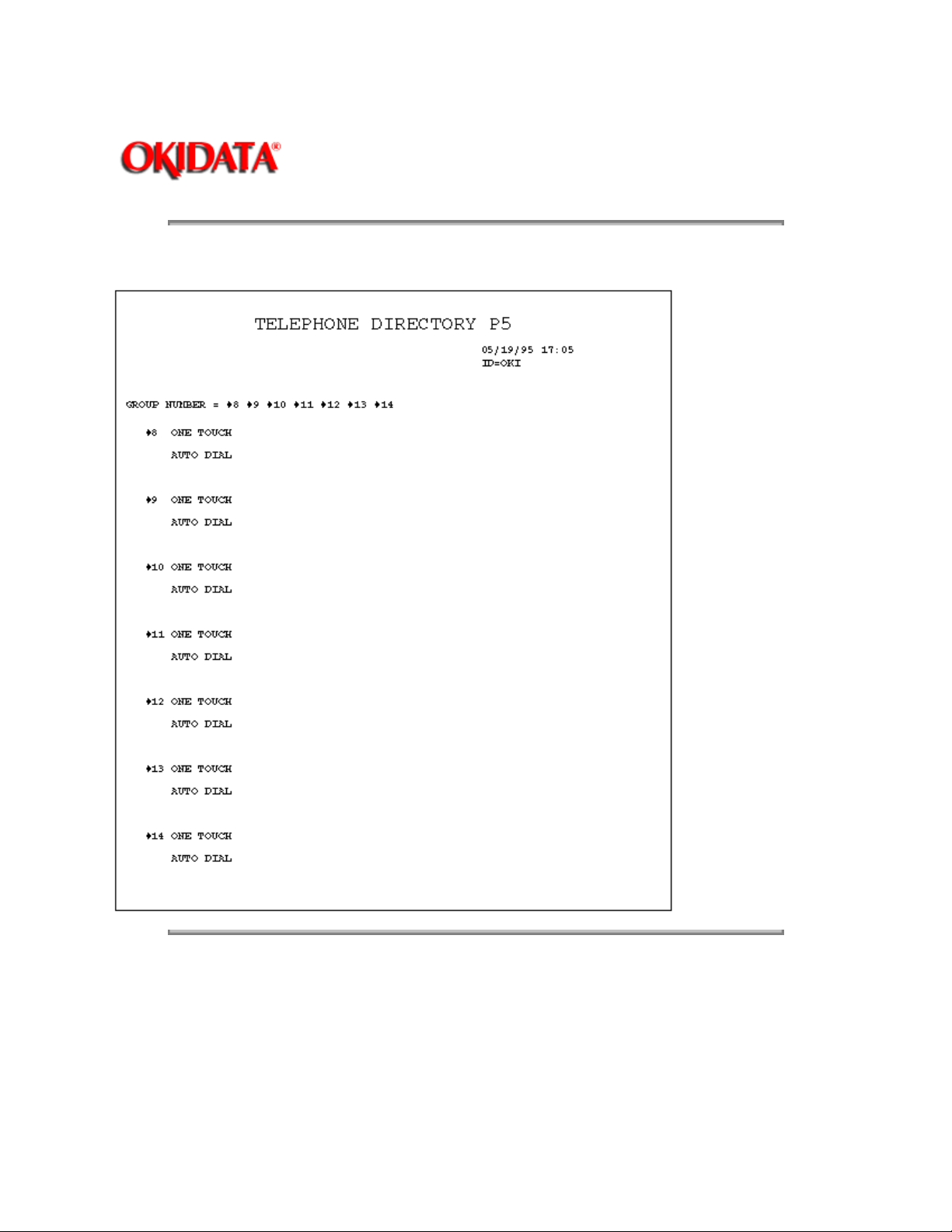
Telephone Directory for OKIFAX 2450 (5/6): (Example)
Page: 27
Copyright 1997, Okidata, Division of OKI America, Inc. All rights reserved. See the OKIDATA Business
Partner Exchange (BPX) for any updates to this material. (http://bpx.okidata.com)
Page 56
Service Guide OF1050/2350/2450
Chapter 1 General Information
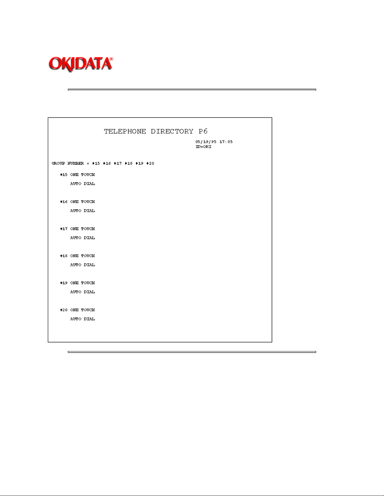
Telephone Directory for OKIFAX 2450 (6/6): (Example)
Page: 28
Copyright 1997, Okidata, Division of OKI America, Inc. All rights reserved. See the OKIDATA Business
Partner Exchange (BPX) for any updates to this material. (http://bpx.okidata.com)
Page 57
Service Guide OF1050/2350/2450
Chapter 1 General Information
No. Item Specifications
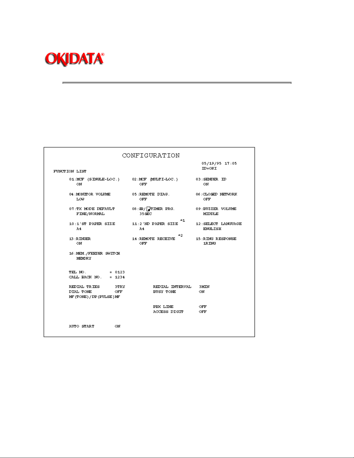
11 Configuration report This report is printed manually.
(REPORT PRINTING +4)
Configuration Report Format:
Configuration Report: Service bit=OFF
Page: 29
*1: When second paper cassette (is installed and paper size is programmed, 2'nd paper size will appear in
No. 11.
*2: OKIFAX 1050/2350 only.
Service Default Report (Configuration Report: Service bit=ON)
Page 58
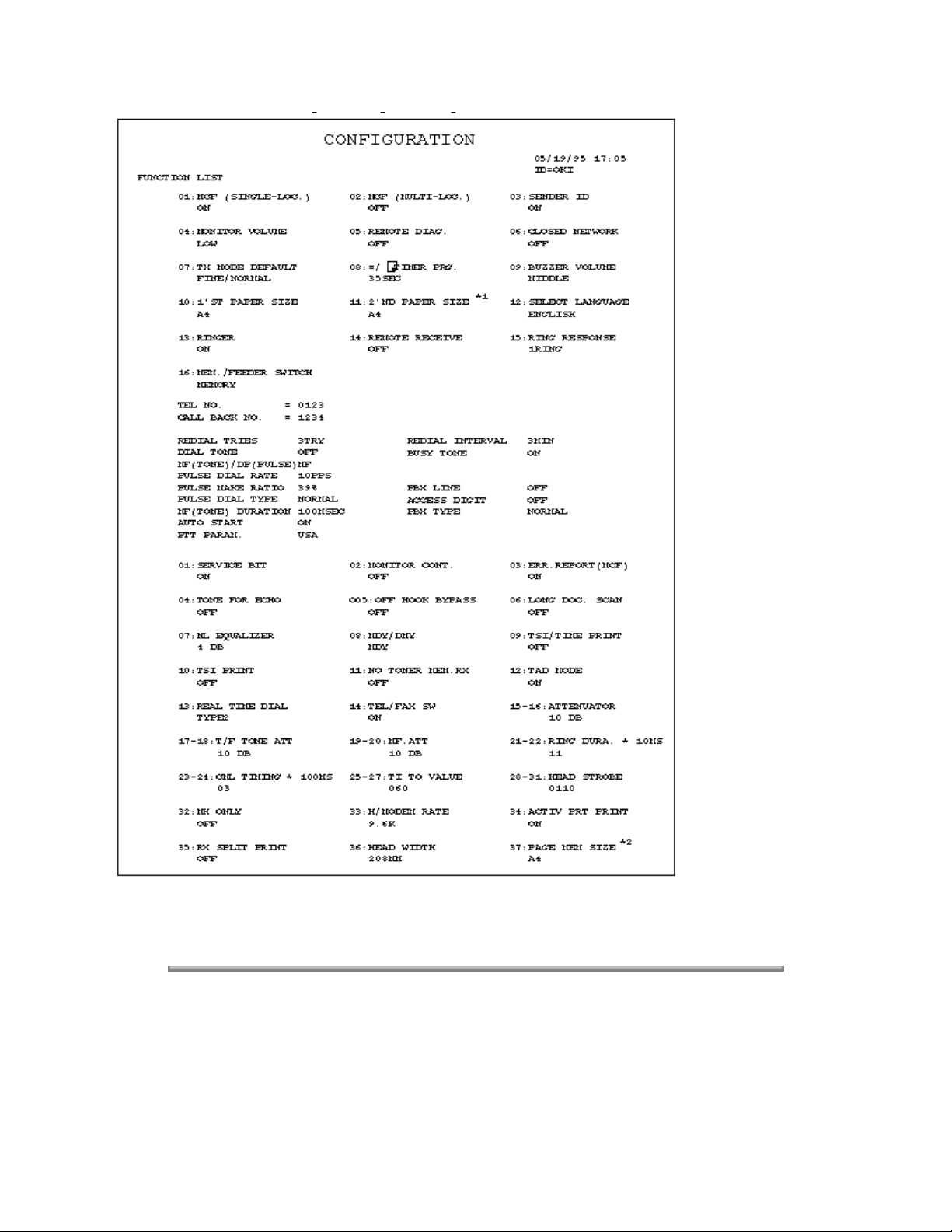
*1: When second paper cassette is installed and paper size is programmed, 2nd paper size will appear in
No.11.
*2: For OKIFAX 2450
Copyright 1997, Okidata, Division of OKI America, Inc. All rights reserved. See the OKIDATA Business
Partner Exchange (BPX) for any updates to this material. (http://bpx.okidata.com)
Page 59
Service Guide OF1050/2350/2450
Chapter 2 Setup Information
A. Setup Information
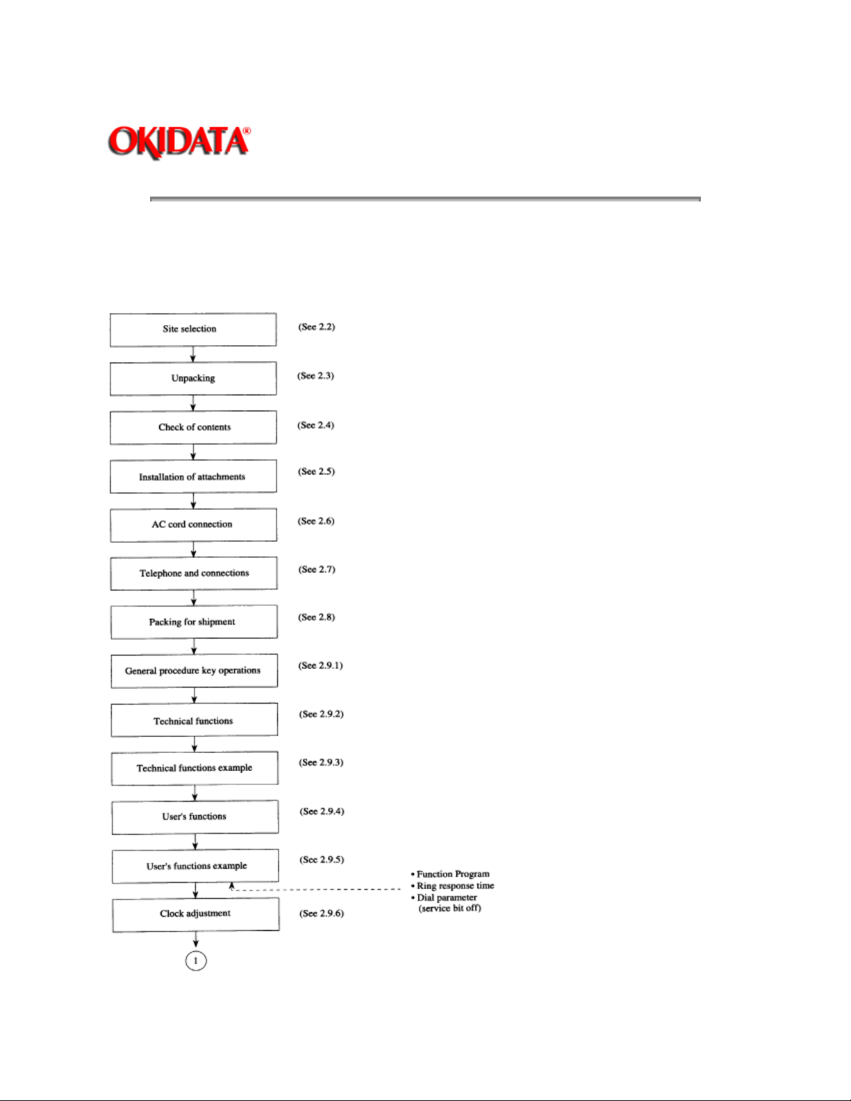
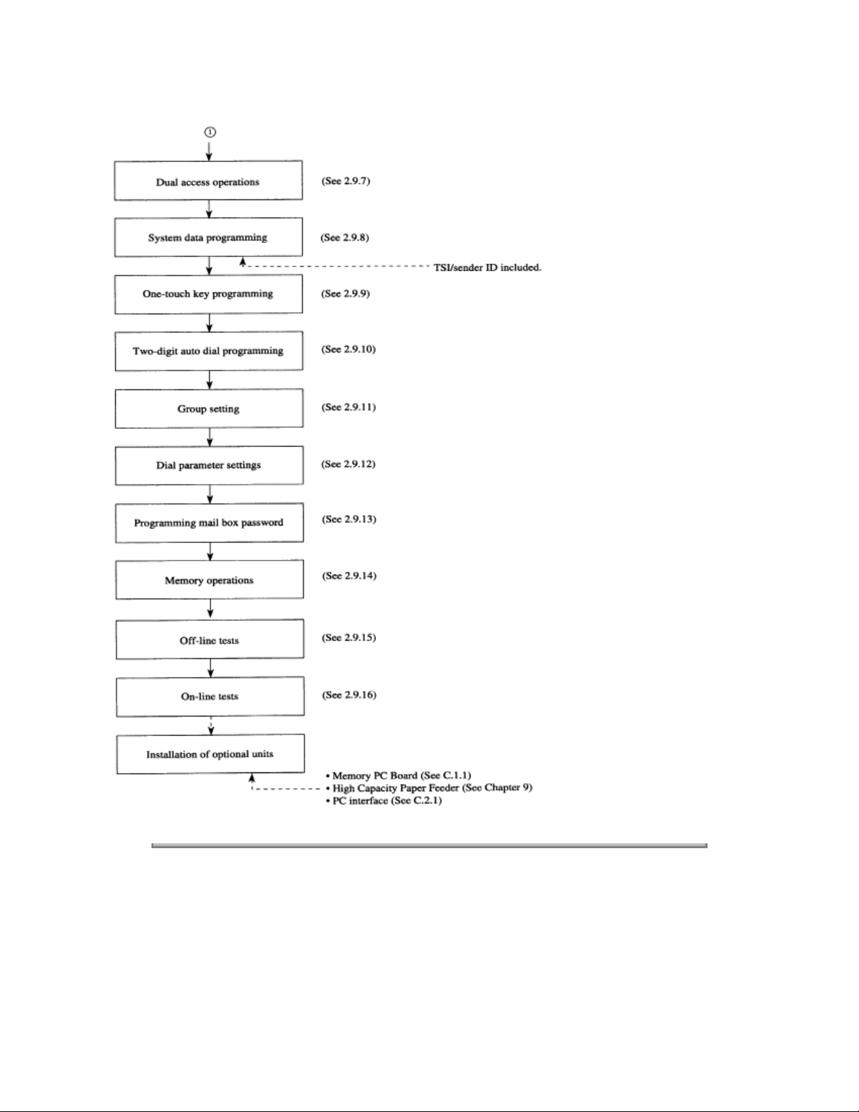
2.1 General
The following flowchart outlines the installation procedure.
Page: 30
Page 60
Copyright 1997, Okidata, Division of OKI America, Inc. All rights reserved. See the OKIDATA Business
Partner Exchange (BPX) for any updates to this material. (http://bpx.okidata.com)
Page 61

2.2 Site Selection
INSTALLATION
Precautions for Installation
2.2.01 Fluctuation in line voltage
120VAC (102V to 127V)
2.2.02 Room temperature
50 to 90°F (10 to 32°C)
2.2.03 Humidity
20 to 80% RH
2.2.04 Operating environment
Pressure: Equivalent of altitude of 8200 feet (2500 m) and below.
Page: 31
Service Guide OF1050/2350/2450
Chapter 2 Setup Information
2.2.05 Exposure
Within five minutes at luminous intensity 2,000 lux (with the stacker cover opened).
2.2.06 Required space for installation
The facsimile requires the space as shown below for safety and good operability.
Page 62
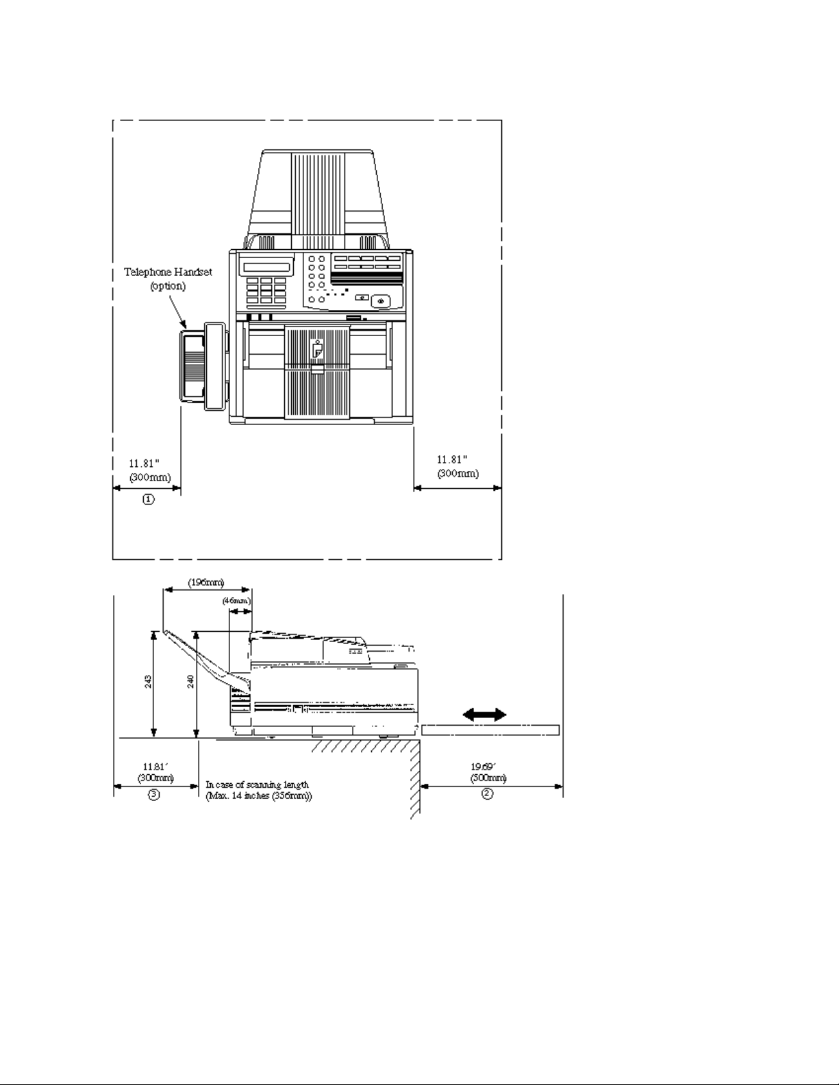
Note:
1 This space is necessary for handling the handset. (option) (page 2-3)
2 This space is necessary for removing the recording paper cassette.
3 This space is necessary for installing the document stacker and to allow space for the fan exhaust.
2.2.07 Levelness of installation surface
1 degree max.
2.2.08 Other requirements
Page 63

Avoid installing in any of the following places:
A location exposed to direct sunlight
A location near a heat source or exposed to vibration
A dusty location
A location with an atmosphere of acid gas, or steam etc.,
A location exposed to quick temperature changes
Copyright 1997, Okidata, Division of OKI America, Inc. All rights reserved. See the OKIDATA Business
Partner Exchange (BPX) for any updates to this material. (http://bpx.okidata.com)
Page 64
Service Guide OF1050/2350/2450
Chapter 2 Setup Information
2.3 Unpacking
Procedure
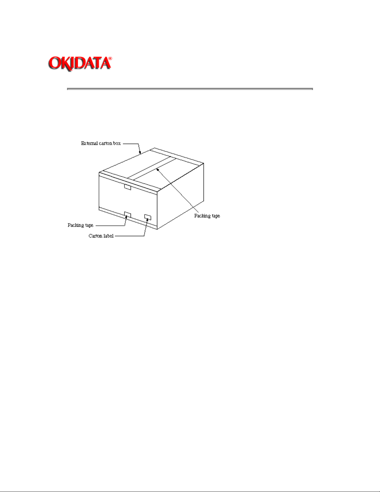
2.3.01 Remove tape on the top of the carton box and open its cover.
Page: 32
Figure 2.3.1 Unpacking Procedure (1)
.
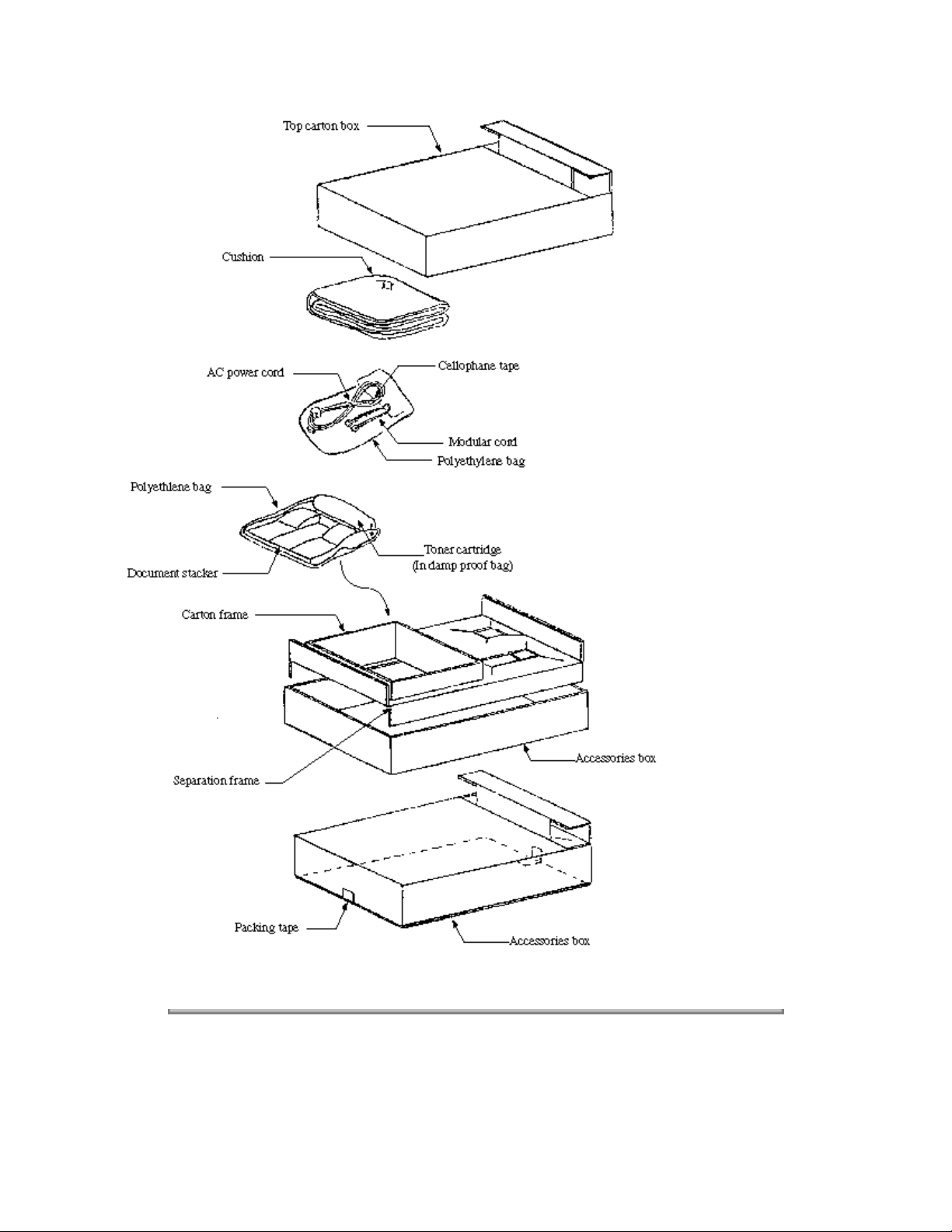
2.3.02 Take out the accessory box from the carton box. (See Figure 2.3.1 below)
2.3.03 Take out the machine with plastic wrapper from the box
Page 65
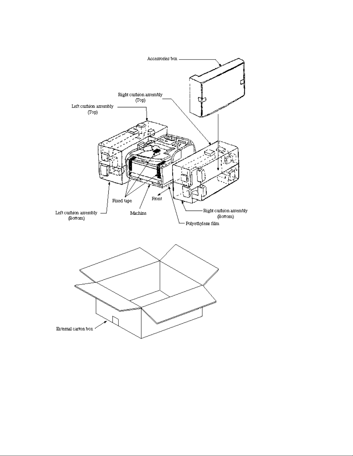
Figure 2.3.1 Unpacking Procedure (2)
Figure 2.3.2 Unpacking Procedure (3)
Page 66
Copyright 1997, Okidata, Division of OKI America, Inc. All rights reserved. See the OKIDATA Business
Partner Exchange (BPX) for any updates to this material. (http://bpx.okidata.com)
Page 67
Page: 33
Service Guide OF1050/2350/2450
Chapter 2 Setup Information
2.4 Check of Contents
After removing the machine and accompanying accessories from the carton box, check the contents
according to the following list:
Table 2.4.1 Contents List
Item No.
1 OKIFAX
2 AC power cord 1
3 I/D unit 1 Already installed.
4 Toner cartridge 1
5 Document stacker 1
6 Line cord 1
7 7 User's guide 1 vol. ODA
Copyright 1997, Okidata, Division of OKI America, Inc. All rights reserved. See the OKIDATA Business
Partner Exchange (BPX) for any updates to this material. (http://bpx.okidata.com)
Name Qty Remarks
1
1050/2350/2450
facsimile
Page 68

Page: 34
Service Guide OF1050/2350/2450
Chapter 2 Setup Information
2.5 Installation of Attachments
2.5.01 Items
Image Drum (ID) Unit (already installed)
Toner cartridge
Recording paper
Document stacker
Copyright 1997, Okidata, Division of OKI America, Inc. All rights reserved. See the OKIDATA Business
Partner Exchange (BPX) for any updates to this material. (http://bpx.okidata.com)
Page 69
Service Guide OF1050/2350/2450
2.5.02 Procedure
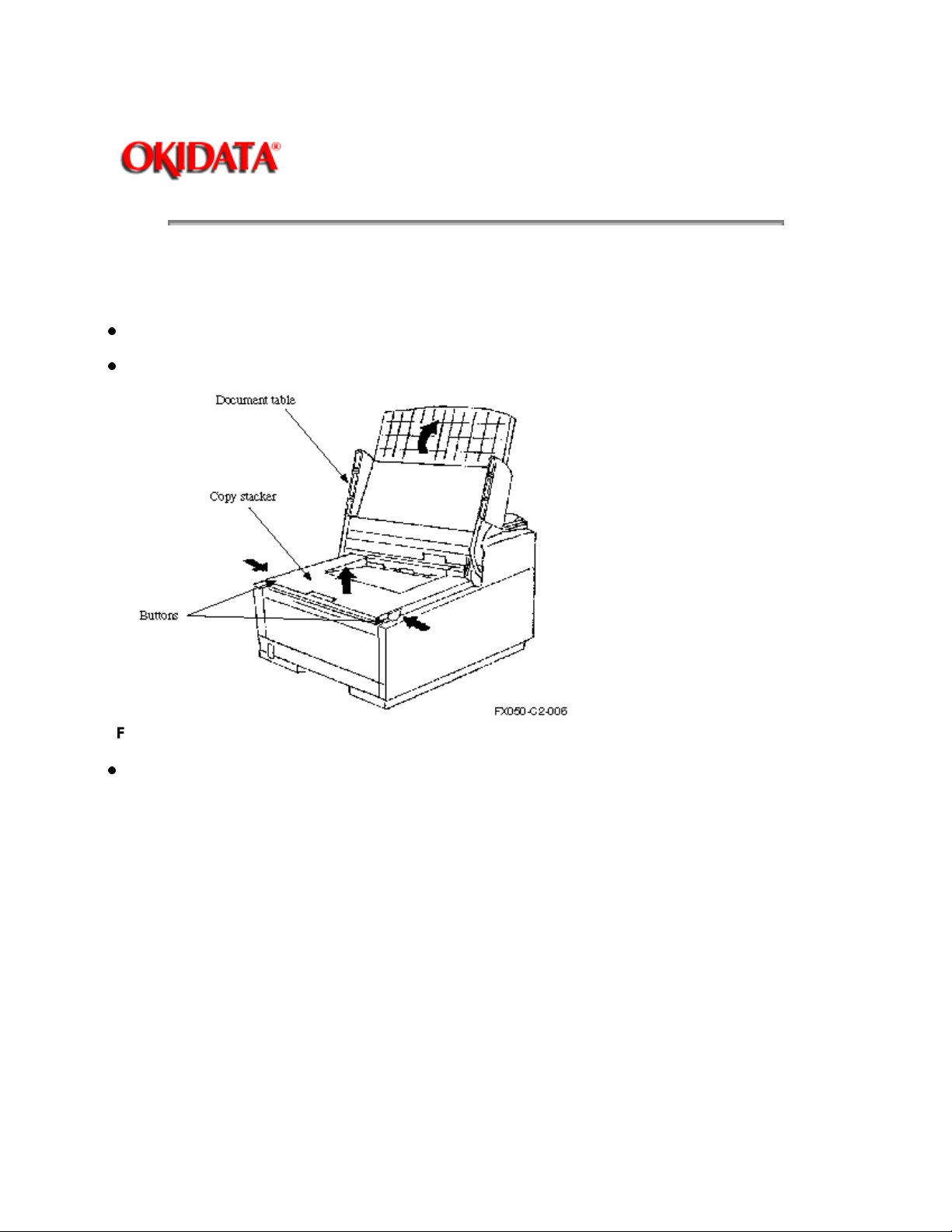
Toner cartridge
Peel off the fixed tape attached on the copy stacker.
Open the document table and copy stacker.
Page: 35
Chapter 2 Setup Information
Figure 2.5.1 Toner Cartridge Installation (1)
.
Take the cushion out of the ID unit
Page 70
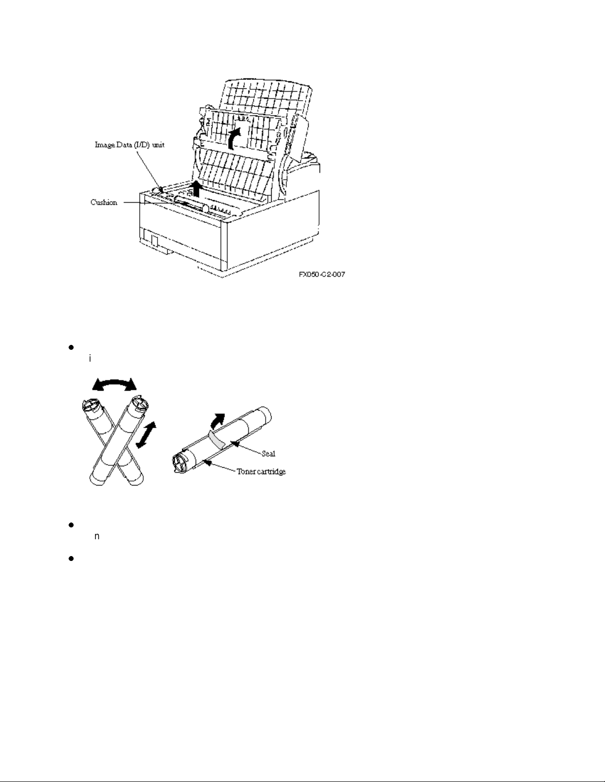
Figure 2.5.2 Toner Cartridge Installation (2)
Installation of Attachments - Continued
Take out the toner cartridge from the damp proof bag, shake it five or six times as shown in the
illustration to eliminate the toner deflection, and peel off the seal gently.
Figure 2.5.3 Toner Cartridge Installation (3)
Ensure that the plastic tab on the right-hand side of the toner cartridge recess lines up with the groove
on the toner cartridge.
Press down on both ends to make sure the cartridge is fully seated.
Page 71
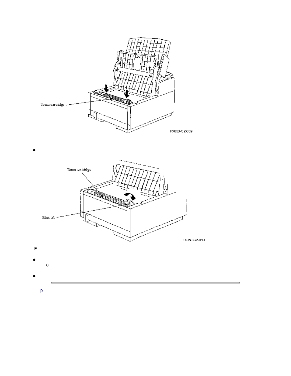
Figure 2.5.4 Toner Cartridge Installation (4)
Push the blue tab forward until it stops.
Figure 2.5.5 Toner Cartridge Installation (5)
Clean the toner scattered in the vicinity of the toner cartridge using a cloth moistened with cold water.
Do not use hot water since it makes the toner stick.
Close the copy stacker so that both latches are locked completely.
Copyright 1997, Okidata, Division of OKI America, Inc. All rights reserved. See the OKIDATA Business
Partner Exchange (BPX) for any updates to this material. (http://bpx.okidata.com)
Page 72
Service Guide OF1050/2350/2450
Chapter 2 Setup Information
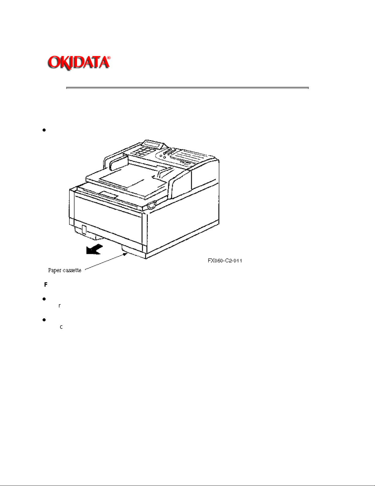
Recording paper
Note:
About 250 sheets of the new paper can be set in the recording paper cassette.
Remove the paper cassette from the facsimile by pulling it straight out.
Page: 36
Figure 2.5.6 Recording Paper Cassette Installation (1)
Sheets must not exceed the paper full marker of the new paper limit indication. If excessive sheets
are loaded, it will cause paper jams.
After loading the new paper, push the cassette forward into the slot at the front of the facsimile until it
locks.
Page 73
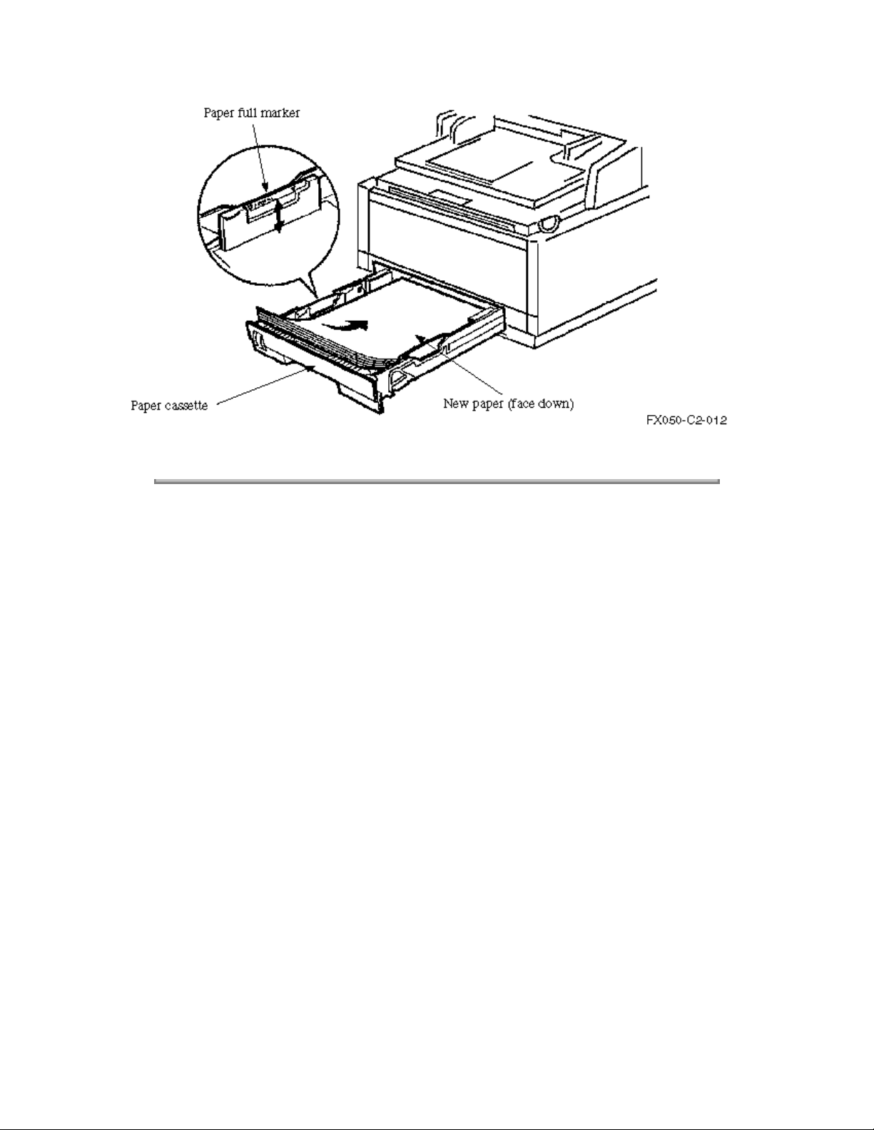
Figure 2.5.7 Recording Paper Cassette Installation (2)
Copyright 1997, Okidata, Division of OKI America, Inc. All rights reserved. See the OKIDATA Business
Partner Exchange (BPX) for any updates to this material. (http://bpx.okidata.com)
Page 74
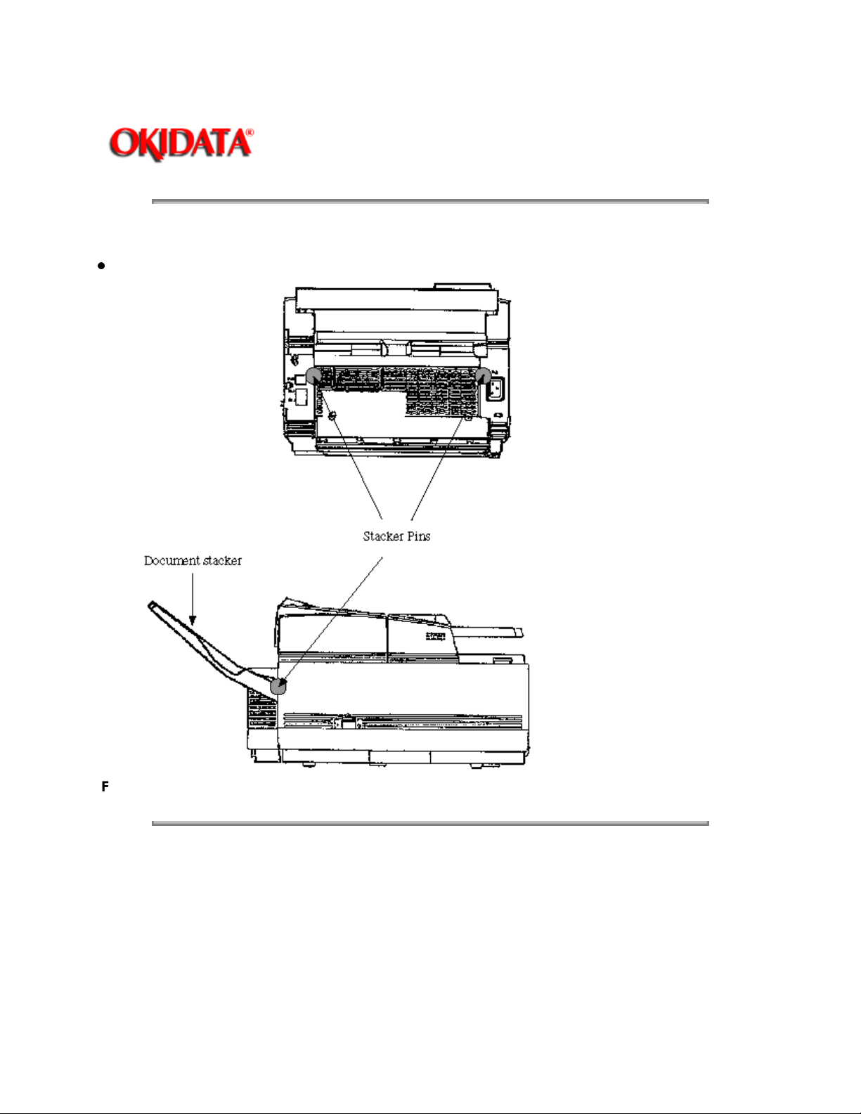
Document stacker
Hang the document stacker onto the stacker pins.
Page: 37
Service Guide OF1050/2350/2450
Chapter 2 Setup Information
Figure 2.5.8 Document Stacker Installation
Copyright 1997, Okidata, Division of OKI America, Inc. All rights reserved. See the OKIDATA Business
Partner Exchange (BPX) for any updates to this material. (http://bpx.okidata.com)
Page 75
Page: 38
Service Guide OF1050/2350/2450
Chapter 2 Setup Information
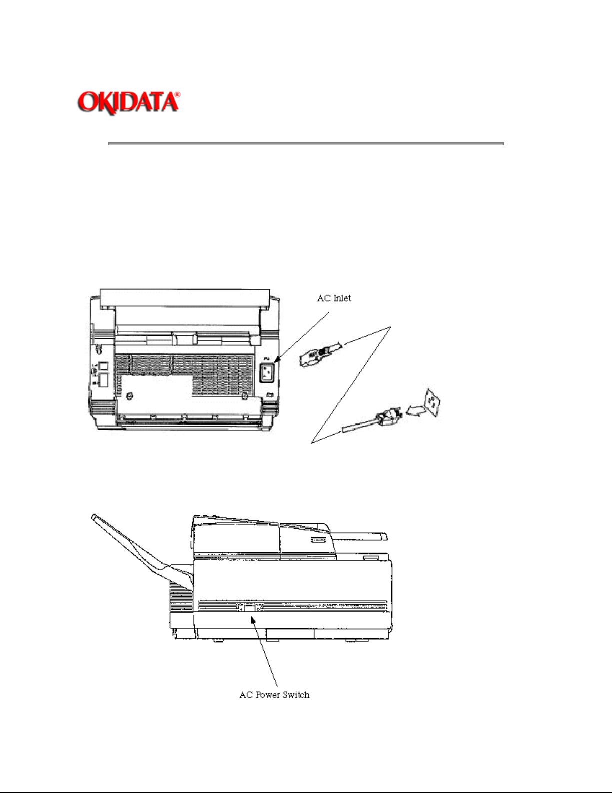
2.6 AC Cord Connection
The power supply is provided as follows.
Nominal input voltage 120VAC (Voltage range 102 to 127VAC)
Check whether the AC voltage of your input is within the above-mentioned voltage range and if so, check
that the power switch is turned OFF. After turning off the power switch, connect the female plug of the AC
cord to the machine and insert the male plug of the AC cord to the inlet receptacle. Turn the power switch
ON and check that the display shows "(Time)" message indicating the standby mode.
Page 76

Copyright 1997, Okidata, Division of OKI America, Inc. All rights reserved. See the OKIDATA Business
Partner Exchange (BPX) for any updates to this material. (http://bpx.okidata.com)
Page 77
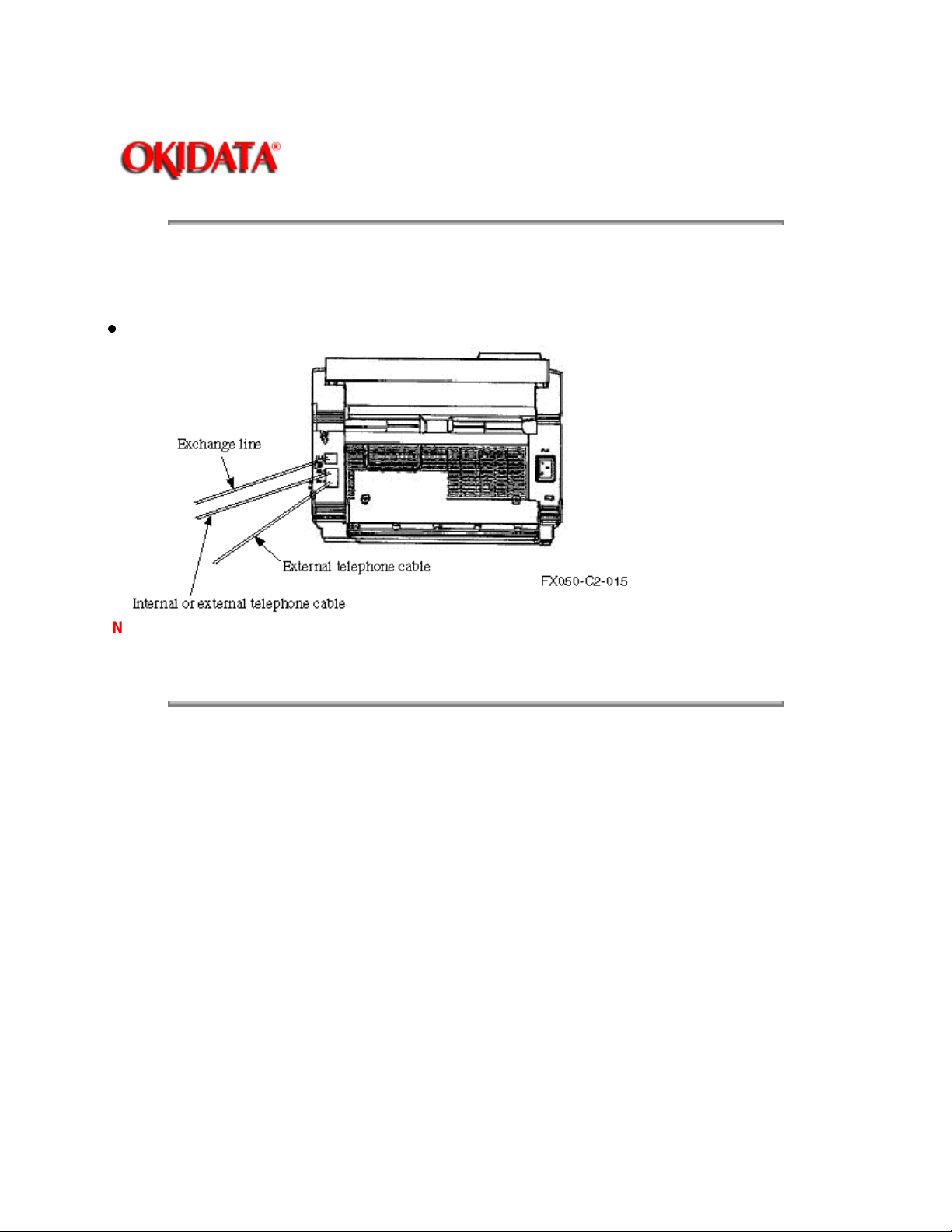
2.7 Telephone and Line Connections
2.7.01 Procedure
Connect the lines.
Page: 39
Service Guide OF1050/2350/2450
Chapter 2 Setup Information
Note:
For US version, telephone cable can be inserted into either upper side or lower side of telephone
terminal.
Figure 2.7.1 Telephone and Line Connections
Copyright 1997, Okidata, Division of OKI America, Inc. All rights reserved. See the OKIDATA Business
Partner Exchange (BPX) for any updates to this material. (http://bpx.okidata.com)
Page 78

2.8 Packing for Shipment
Page: 40
Service Guide OF1050/2350/2450
Chapter 2 Setup Information
CAUTION:
TONER FROM THE UNIT AND SHIP SEPARATELY! Failure to do this will result in damage to the
machine.
Copyright 1997, Okidata, Division of OKI America, Inc. All rights reserved. See the OKIDATA Business
Partner Exchange (BPX) for any updates to this material. (http://bpx.okidata.com)
When packing the OKIFAX 1050/2350/2450 for shipment,
REMOVE THE IMAGE DRUM AND
Page 79

Service Guide OF1050/2350/2450
Chapter 2 Setup Information
B. Programming and Initial Settings
2.9 Initial Settings
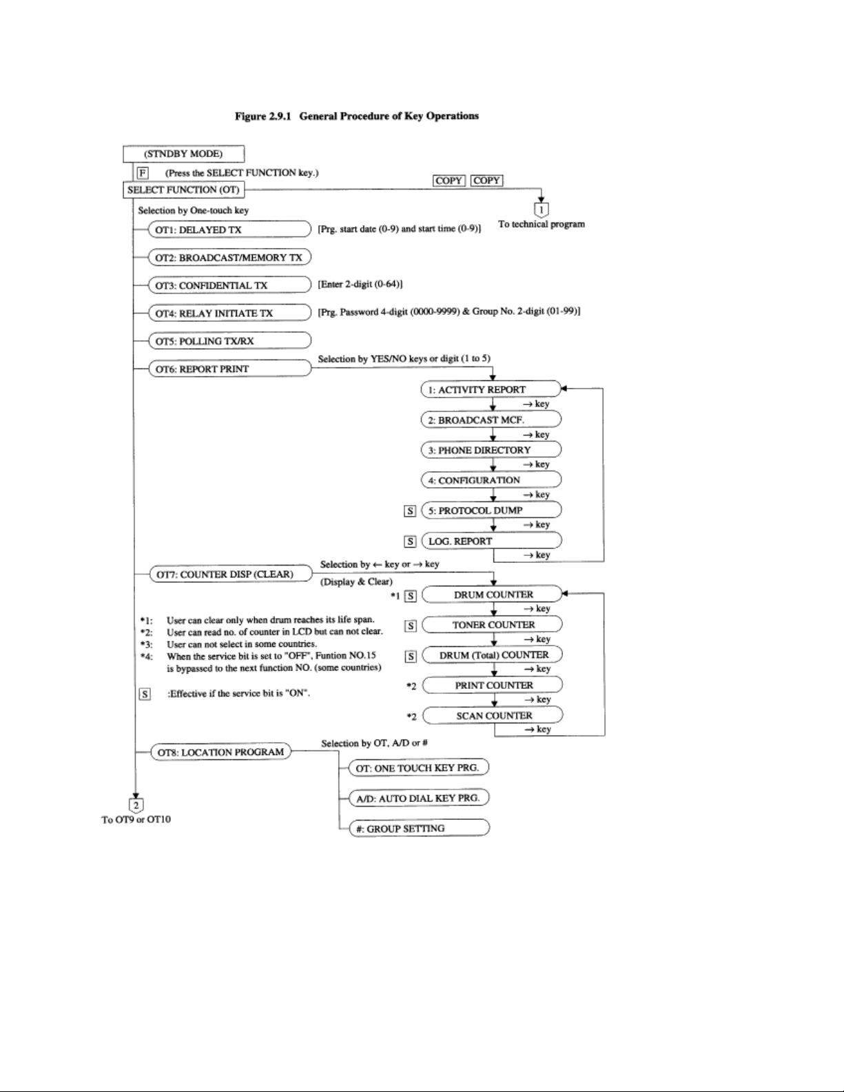
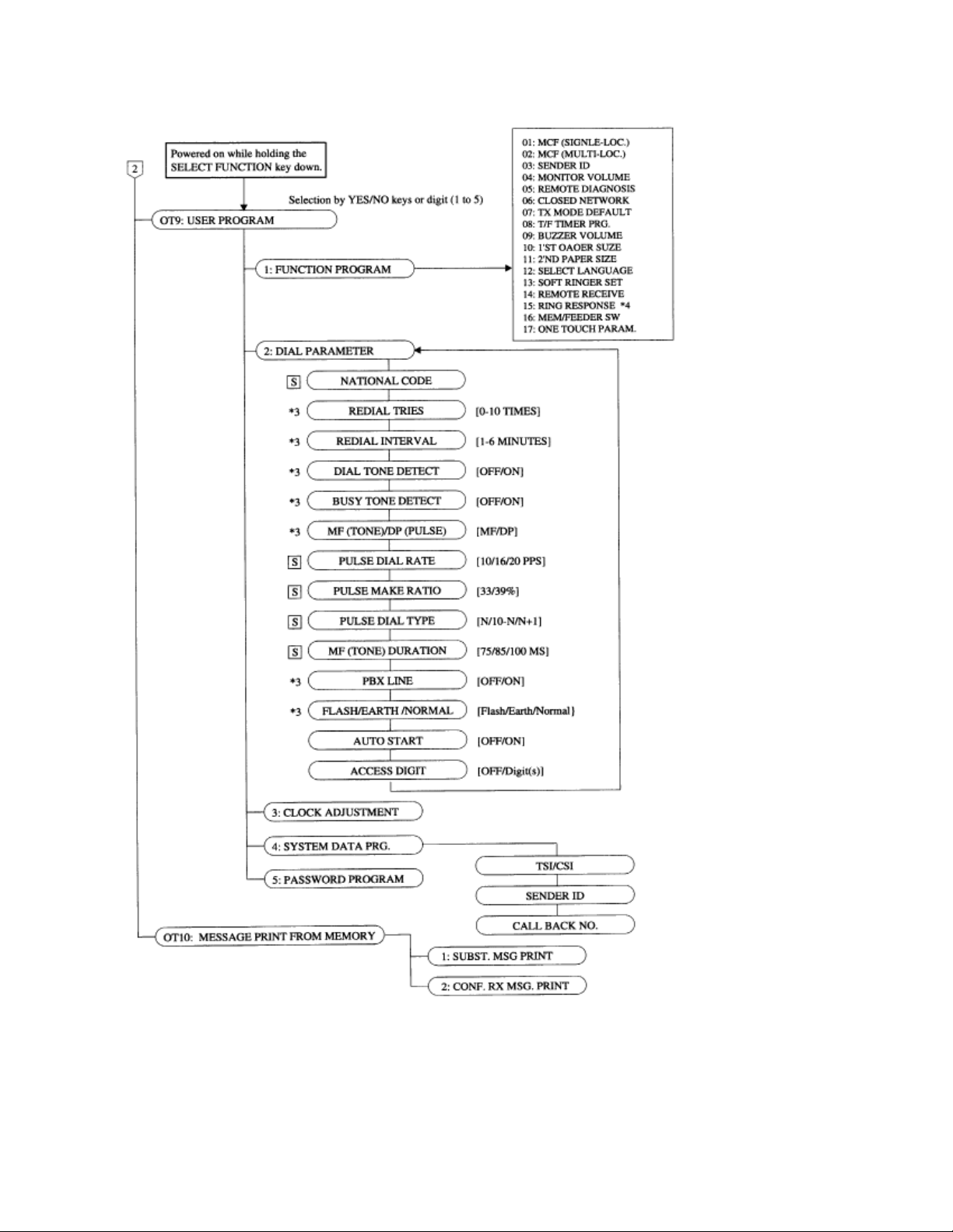
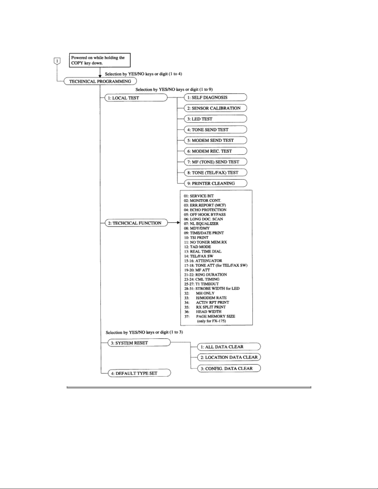
2.9.1 General Procedure of Key Operation
Figure 2.9.1 shows the general procedure of key operation.
Page: 41
Page 80
Page 81
Page 82
Copyright 1997, Okidata, Division of OKI America, Inc. All rights reserved. See the OKIDATA Business
Partner Exchange (BPX) for any updates to this material. (http://bpx.okidata.com)
Page 83
Page: 42
Service Guide OF1050/2350/2450
Chapter 2 Setup Information
2.9.2 Technical Functions
This section explains setting items generally conducted by service personnel, not by users.
Table 2.9.1 shows the initial setting items and their purposes. (The default setting is different by the
individual countries.) Each item can be accessed by entering the corresponding service number on
Technical Function.
The detailed procedures of the initial setting items will be explained on the following pages.
Note:
The display shows:
(For Example)
Note 1:
Note 2:
OFF=0, ON=1
MDY=0, DMY=1
without EQL=0, EQL1=1, EQL2=2, EQL3=3 (for cable EQL)
OFF=0, TYPE1=1, TYPE=2 (for REAL TIME DIAL and TAD MODE)
OFF=0, ONCE=1, ALL=2 (for TIME/DATA PRINT)
0dB~15dB=00~15(ATTENUATOR etc.)
100ms~990ms=10~99 (for RING DURATION: x 10ms)
100ms~1900ms=01~19 (for CML TIMING: x 100ms)
000sec.~255sec.=000~255 (T1 TIMEOUT VALUE: x 1sec.)
14.4k=0, 9.6k=1, 4.8k=2
LEGAL=0, A4=1
208MM=0, 216MM=1
S-ON:
*10
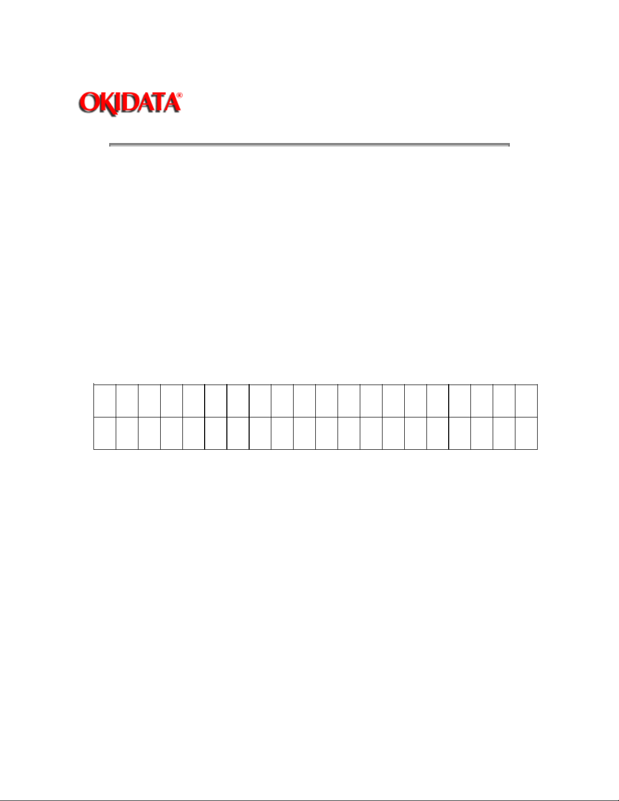
1
*20 1 0 0 0 0 1 0 0 0 0 2 1 5 0 9 0 0 1 1
*31 1 0 3 0 5 9 0 1 1 0 0 1 0 0 0 0
*1212223242526272829303132333435363738394
Effective if the service bit has been set to ON.
FP:
Function program setting
TF:
Technical function setting
0203040506070809101112131415161718192
*1: Technical Function Number.
*2: Function assignment of LCD upper row.
*3 Function assignment of LCD lower row.
0
0
Table 2.9.1 (1/8) Service Personnel Initial Settings
Page 84

TF No. No. Item Specifications Default
_________________________________________________________________________________
01 Service bit Switching serviceman/user operation. OFF
(0)
ON (1): Service personnel's features are available.
OFF (0): Service personnel's features are not available.
To enable or disable the following functions:
• Drum (Total) and toner counter clear
• Protocol dump
• Dial parameters
02 Line monitor control Changing the audible monitoring range. OFF
FP +04 (To select the loudness of monitoring) (0)
ON (1): Enable
OFF (0): Disable
Note: In case of transmission mode, the monitor
will be available during dialing, but the monitor will
be switched off automatically after the elapse of
specified time (about 5 sec.).
03 Error report (MCF) Enables or disables the automatic printing of the OFF
MCF: Message Confirmation message confirmation report upon a (0)
Report communicationerror.
ON (1): Printing the error report. An error report
which is different from FP No. 2 is printed
out for each single location.
OFF (0): Disable
04 Echo protection Enables echo suppression for poor lines with OFF
echo, usually during overseas transmission. (0)
This bit setting controls the following features.
Echo Protection OFF (0) ON (1)
Ignore 1st DIS OFF ON
CED-DIS timer 75 ms 1.5 sec
Tone for echo OFF ON
05 Off-hook bypass Allows two machines to be connected back to OFF
back for testing purposes. (0)
Page 85
ON (1): Enable
OFF (0): Disable
06 Long document SCAN Enables the transmission of long-size document OFF
(more than 14" (356 mm). (0)
ON (1): Unlimited
OFF (0): 14" (356 mm.)
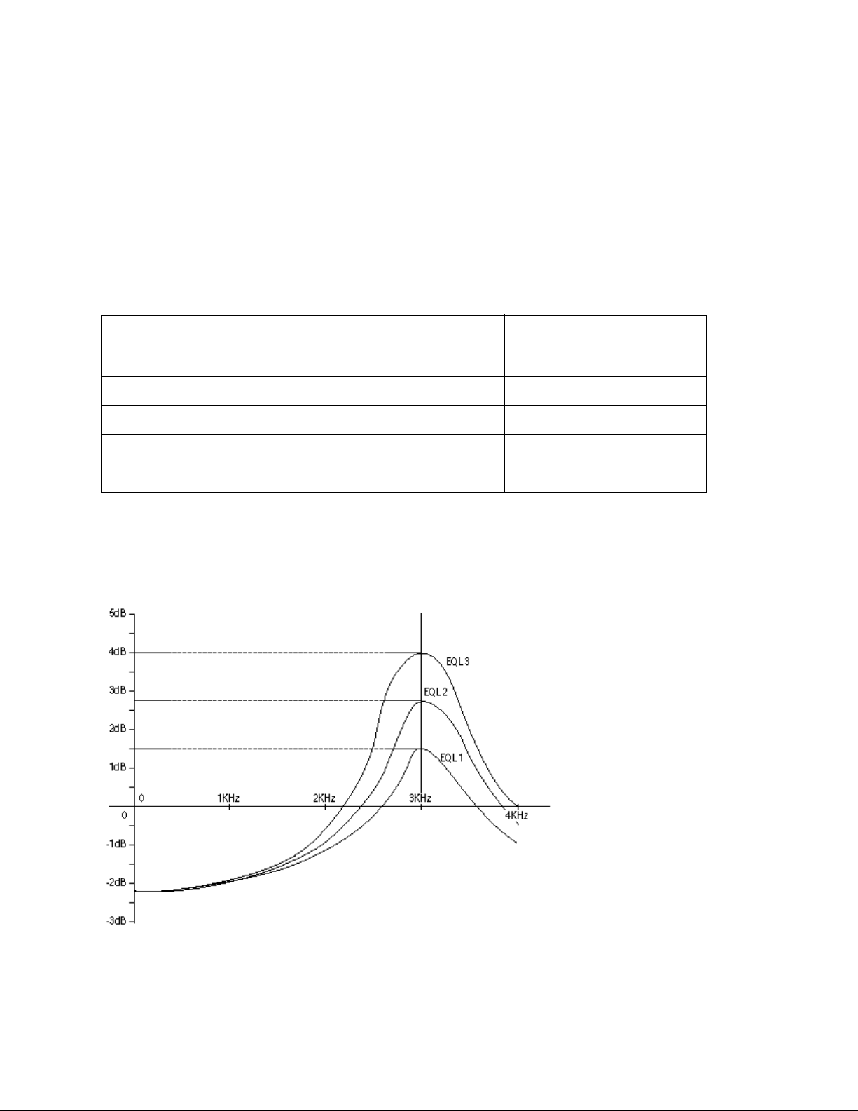
07 Cable equalizer Determining the adequate equalizing level of the
cable. EQL1, EQL2, EQL3 and without EQL are
selectable.
Setting value Setting for OKIFAX 2350 and
OKIFAX 2350 with
14.4 Kbps modem
0 without EQL without EQL
1 EQL1 EQL3 *1
2 EQL2 EQL3 *1
3 EQL3 EQL3 *1
*1: The equalizer is effective for both sending and receiving sides.
Note:
By this adjustment you can tune up your equipment to the inversed characteristic of the cable.
Figure 2.9.2 shows the characteristics of the cable equalizer.
Setting for OKIFAX 1050 and
OKIFAX 2350 with
9.6Kbps modem
Figure 2.9.2 Characteristics of the Cable Equalizer (EQL1, EQL2 and EQL3)
08 MDY/DMY Switches LCD display and report print MDY
Page 86

from month/day/year to day/month/year (0)
or vice versa.
MDY=0, DMY=1
09 Time and date print Enables or disables the function of printing OFF
local date and time at the top of the (0)
received page.
Note: User programming of this function is an
FCC requirement.
Time and date print Setting
OFF 0
ONCE 1
ALL pages 2
Note: Set at receiver.
Except memory reception.
10 TSI print Enables the printing of TSI data ON
from a remote fax onto the received pages. (1)
TSI is printed at the leading edge of first
reproduced copy. (Set at receiver.)
When TF09 is set to "ALL", TSI is printed
for the all received pages.
ON (1): Enable
OFF (0): Disable
(Reference)
TSI; Transmitting Subscriber Identification
11 No-toner memory reception Enables or disables the memory reception ON
when the fax is in no toner condition. (1)
When TF09 is set to "ALL", TSI is printed
for the all received pages.
ON (1): Enable
OFF (0): Disable
(Reference)
TSI; Transmitting Subscriber Identification
11 No-toner memory reception Enables or disables the memory reception ON
when the fax is in no toner condition. (1)
ON (1): The messages are printed when
toner has been newly supplied or an operator
per-forms the memory operation (OT10).
Page 87
OFF (0): The messages are printed in the
print mode. But print quality is not guaranteed.
12 TAD mode Allows the OKIFAX to share a telephone TYP2
(For external telephone line with an answering device. (2)
answering device).
TAD mode is of two types (TYPE1/TYPE2).
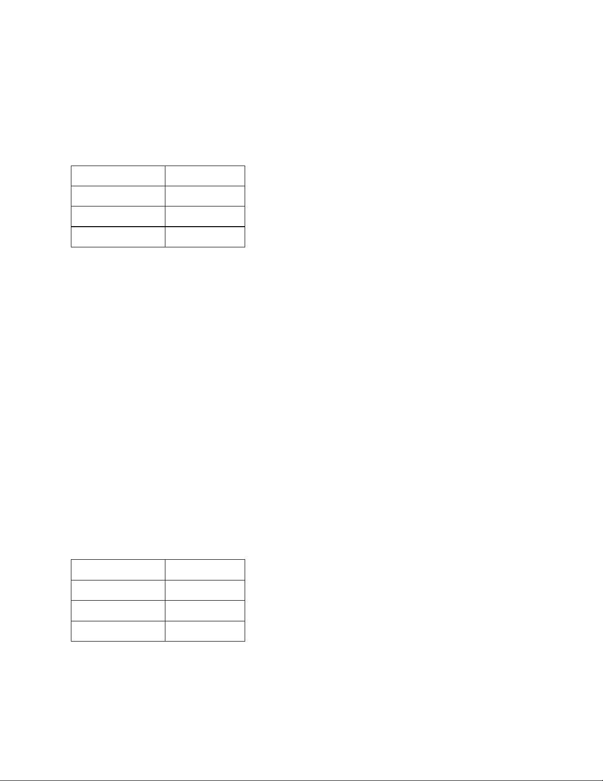
TAD mode Setting
OFF 0
TYPE1 1
TYPE2 2
TYPE1 means:
1. RING comes.
2. The TAD answers, returns the recorded
voice mes-sage in TAD to calling party.
3. The FAX machine will continue to
detect CNG while TAD works.
4. If the FAX machine detects CNG
signal, the fax will go into normal
receiving mode.
5. Even though the fax does not detect
CNG signal, the fax will go to receiving
mode when answering machine
disconnects.
TYPE2 means:
Same as TYPE1 (above) except No. 5 (listed
below).
5. If the fax does not detect CNG signal during
TAD operation, the machine will go to standby
mode.
13 Real time dialing Enables or disables this feature. TYP2
3 types selectable. (2)
Type Setting
OFF 0
TYPE1 1
TYPE2 2
TYPE1: Real-time dialing is available when the
optional telephone handset is OFF-HOOK.
TYPE2: Real-time dialing is available when the
optional telephone handset is OFF-HOOK or
Page 88

HOOK key is pressed.
14 TEL/FAX switching Enables or disables the TEL/FAX automatic ON
switching. If this function is disabled, (1)
TEL/FAX mode will not appear as a
receive option.
ON (1): Enable
OFF (0): Disable
(Related item: FP08, TF17-18)
15 Modem attenuator Adjusts the attenuation (dB) for the message 10 dB
send signal power level.
16 Adjusting value is 0 to 15 dB in one dB steps.
Since the maximum send signal power level
(dB) of the fax is at 0 dB, you can select
0 dB to -15 dB in one dB steps for the send
signal power level.
Note: The send signal power level should meet
your country's regulation. Some countries
may specify the power level at a telephone
exchange.
In that case, you should subtract the
specified level from the line cable attenuation to
determine the send level of your fax.
Bit 15 Bit 16 dB
0 0 0
0 1 1
0 2 2
0 3 3
0 4 4
0 5 5
0 6 6
0 7 7
0 8 8
0 9 9
Bit 15 Bit 16 dB
1 0 10
Page 89
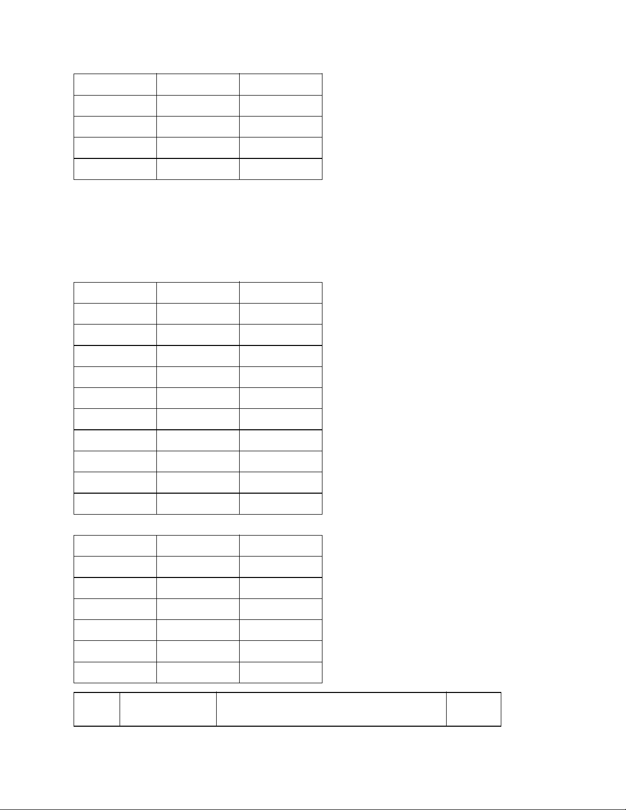
1 1 11
1 2 12
1 3 13
1 4 14
1 5 15
17 T/F tone attenuator Adjusts the attenuation (dB) for the 10 dB
tone send signal
18 (for TEL/FAX SW) for TEL/FAX switching.
Adjusting value is 0 to 15 dB in one dB steps.
Bit 17 Bit 18 dB
0 0 0
0 1 1
0 2 2
0 3 3
0 4 4
0 5 5
0 6 6
0 7 7
0 8 8
0 9 9
Bit 17 Bit 18 dB
1 0 10
1 1 11
1 2 12
1 3 13
1 4 14
1 5 15
T.F.
No.
Item Specifications Default
Page 90
19
20
Bit 19 Bit 20 dB
0 0 0
0 1 1
0 2 2
0 3 3
0 4 4
0 5 5
0 6 6
0 7 7
0 8 8
MF attenuator Adjusts the attenuation (dB) for the send MF
tone power level.
Adjusting value is 0 to 15 dB in one dB
6 dB
0 9 9
Bit 19 Bit 20 dB
1 0 10
1 1 11
1 2 12
1 3 13
1 4 14
1 5 15
T.F.
No.
21
22
Item Specifications Default
Ring duration
detection time
Selects the minimum ring detection time to
meet country's requirements.
Adjusting time is 100 MS to 990 MS in 10 MS
steps.
120
(MS)
Bit 21 Bit 22
1 2
For example: (120 ms)
Page 91

12 x 10 ms = 120 ms
T.F.
No.
23 CML timing Selects the time from end of ring to CML-ON.
24
Bit 23 Bit 24
0 3
T.F.
No.
25
26
27
Item Specifications Default
Adjusting
time is 100 MS to 1900 MS in 100 MS steps.
For example: (300 ms)
03 x 100 ms = 300 ms
Item Specifications Default
T1, timeout value
(XTTO value)
Registers the time duration (in seconds) for which the
fax
waits for the remote station's answer.
This timer starts when the last dial digit has been sent
in the automatic transmission mode. As the special
case, when 000 is selected, the following
predetermined values will be used. * Selects the 3
digit timer (000 to 255 sec)
300
(MS)
59
(Sec)
Bit 25 Bit 26 Bit 27
0 5 9
T.F.
No.
Item Specifications Default
For example: (59 sec)
Page 92
28
29
30
31
Strobe for LED
head
Setting of LED print head strobe signal.
Note 1: When the rank marking of the new re-placed
LED print head (new part) is same as that of the old
used LED print head (old part), you do not always
have to set the LED print head strobe signal.
Note 2: Intensity ranking is determined by the first,
second and third digits from the right on the LED print
head serial number (i. e. in S/N ........056, 056 is the
intensity ranking.)
0110
Rank
Marking
~
056
057 ~
063
064 ~
071
072 ~
080
Tec
hnic
al
Fun
ctio
n
No. 31
No. 30
No. 29
No. 28
0 1 0 1 0 1 0 1 0 1 0 1 0 1 0 1
0 0 1 1 0 0 1 1 0 0 1 1 0 0 1 1
0 0 0 0 1 1 1 1 0 0 0 0 1 1 1 1
0 0 0 0 0 0 0 0 1 1 1 1 1 1 1 1
*
*
*
*
081 ~
090
091 ~
101
102 ~
113
114 ~
127
128 ~
143
*
*
*
*
*
Page 93
144 ~
160
*
161 ~
180
181 ~
202
203 ~
227
228 ~
256
257 ~
287
288 ~ *
T.F.
No.
32 MH only Switches the function of limiting image compres-sion
Item Specifications Default
only to the MH codes.
ON (1): Coding scheme is MH only. When the
receiving image data is affected by noise on the
telephone line. OFF (0): Any of MH, MR and MMR.
*
*
*
*
*
OFF
(0)
33 High-speed
modem rate
Modem Rate Setting
14.4 k 0
9.6 k 1
4.8 k 2
T.F.
No.
Item Specifications Default
Specifies the modem's starting speed, 14.4k, 9.6k, or
4.8kbps.
When 9.6k modem is installed, the default value is set
to "9.6k (1)".
14.4k
(0)
Page 94

34 ACTIV RPT PRINT
(activity report
print)
Enables or disables the automatic printing of the
activity
report when 30 communications have been recorded
in
the internal memory.
ON (1): Automatic printing
OFF (0): Disable
14.4k
(0)
35 RX split print Specifies whether to print a received document longer
than the recording paper size with splitting into the
upper and lower parts or to print it only for the portion
covered by one recording paper sheet without
splitting.
ON (1): Splitting
OFF (0): No splitting.
36 Head width You should confirm the head width by the following
table, and then select it by this setting. (Refer to
4.2.1.)
Head width Head label Setting
8.19" (208
mm)
8.5" (216 mm) A4 200 1
T.F.
No.
Item Specifications Default
1115G2 0
OFF (0)
8.19"
(208
MM) (0)
37 Page memory size
(only for OKIFAX
2450)
Copyright 1997, Okidata, Division of OKI America, Inc. All rights reserved. See the OKIDATA Business
Partner Exchange (BPX) for any updates to this material. (http://bpx.okidata.com)
Selects the page memory size for A4 and LEGAL in
order to use the message memory effectively.
LEGAL (1): Available LEGAL
A4 (0): Not available LEGAL
Note: In OKIFAX 2450, if you print out Legal size
documents, you should select LEGAL setting.
Reduction from LEGAL to LETTER is avail-able
only when Legal size is selected by this function.
LEG
(0)
Page 95

Service Guide OF1050/2350/2450
Chapter 2 Setup Information
2.9.2.02 TEL/FAX automatic switching
This function is used for the purpose of TEL/FAX automatic switching as follows.
If the machine detects a call with a
document receiving operation.
CNG
signal indicating an auto send facsimile call, it starts an automatic
Page: 43
If machine detects a call without a
The calling person can hear a ring back tone for up to 35 seconds.
If the operator at the called side does not lift the handset within 35 seconds, the machine automati-cally
starts a document receiving operation. Voice conversation will automatically be available through the
internal handset by lifting up the handset while the call buzzer is sounding.
Note:
In this mode, following four settings are required.
1: The predetermined time is selectable between 20 or 35 sec. (Function program No. 08)
2: No ringing signal is sent to the external telephone handset.
Copyright 1997, Okidata, Division of OKI America, Inc. All rights reserved. See the OKIDATA Business
Partner Exchange (BPX) for any updates to this material. (http://bpx.okidata.com)
CNG
signal, machine generates the buzzer sounds as a telephone call.
Page 96

Page: 44
Service Guide OF1050/2350/2450
Chapter 2 Setup Information
2.9.2.03 TAD mode
TAD: Telephone Answering Device
TAD can be connected to external telephone terminal to record your messages.
TAD records your speech and switches an automatic voice message response to the calling station.
Note 1:
Note 2:
proper operation)
Note 3:
(Technical function No. 17, 18)
Copyright 1997, Okidata, Division of OKI America, Inc. All rights reserved. See the OKIDATA Business
Partner Exchange (BPX) for any updates to this material. (http://bpx.okidata.com)
A choice of TAD mode is available by Technical Function No. 12.
The predetermined time is selectable between 20 or 35 sec. (35 seconds is recommended for
Choice of message sending level. The level is selectable from 0 to 15 dB in one dB step.
Page 97
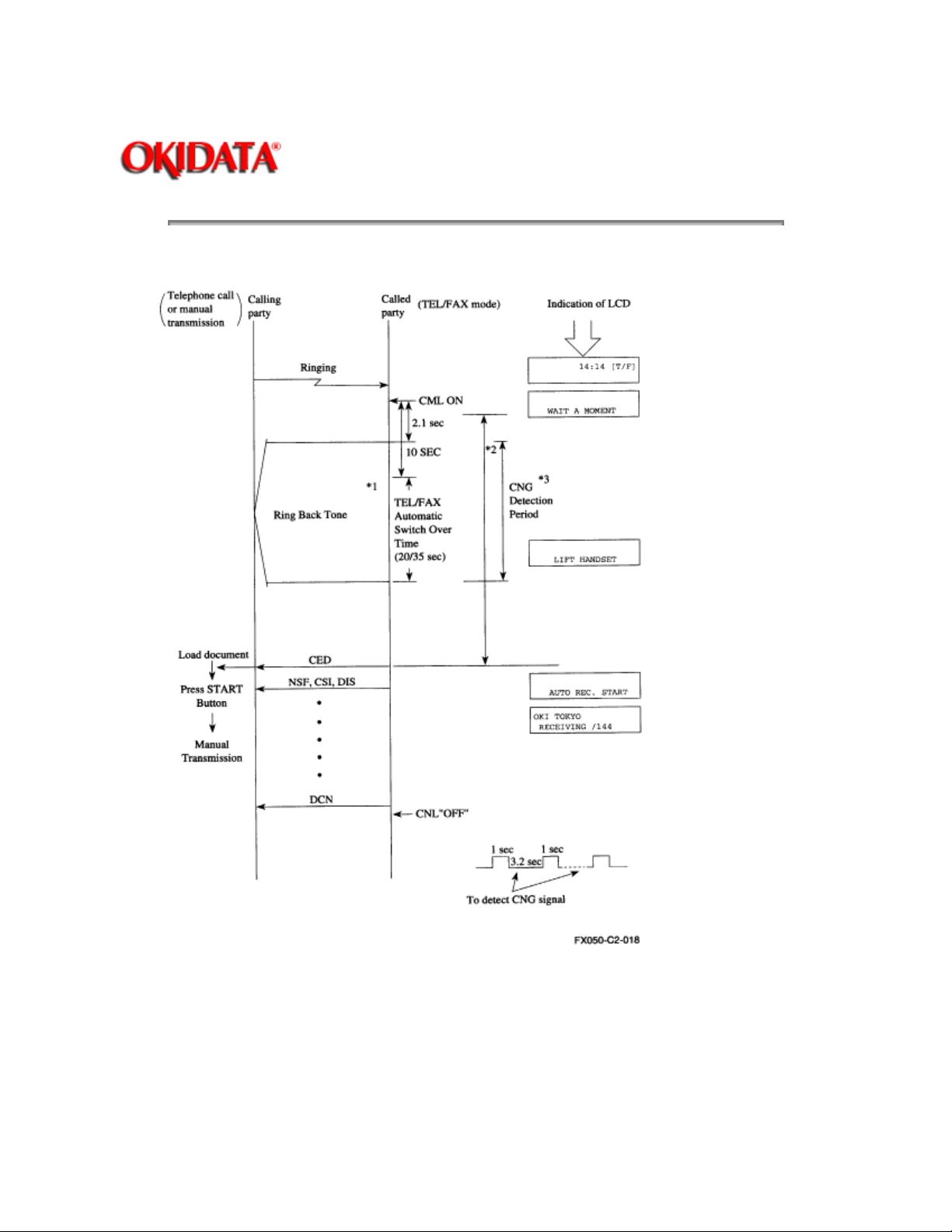
TEL/FAX mode flow chart
Page: 45
Service Guide OF1050/2350/2450
Chapter 2 Setup Information
Notes:
*1: Ring Back Tone 1 sec. ON, 3.2 sec. OFF
*2: When you want to talk by phone, pick up handset.
Page 98

*3: The called party can send CED to the calling party immediately to start FAX communication if the CNG
is detected during the period.
*4: If the fax does not detect CNG signal during working of TEL/FAX mode, LCD display indicates "LIFT
HANDSET".
Copyright 1997, Okidata, Division of OKI America, Inc. All rights reserved. See the OKIDATA Business
Partner Exchange (BPX) for any updates to this material. (http://bpx.okidata.com)
Page 99
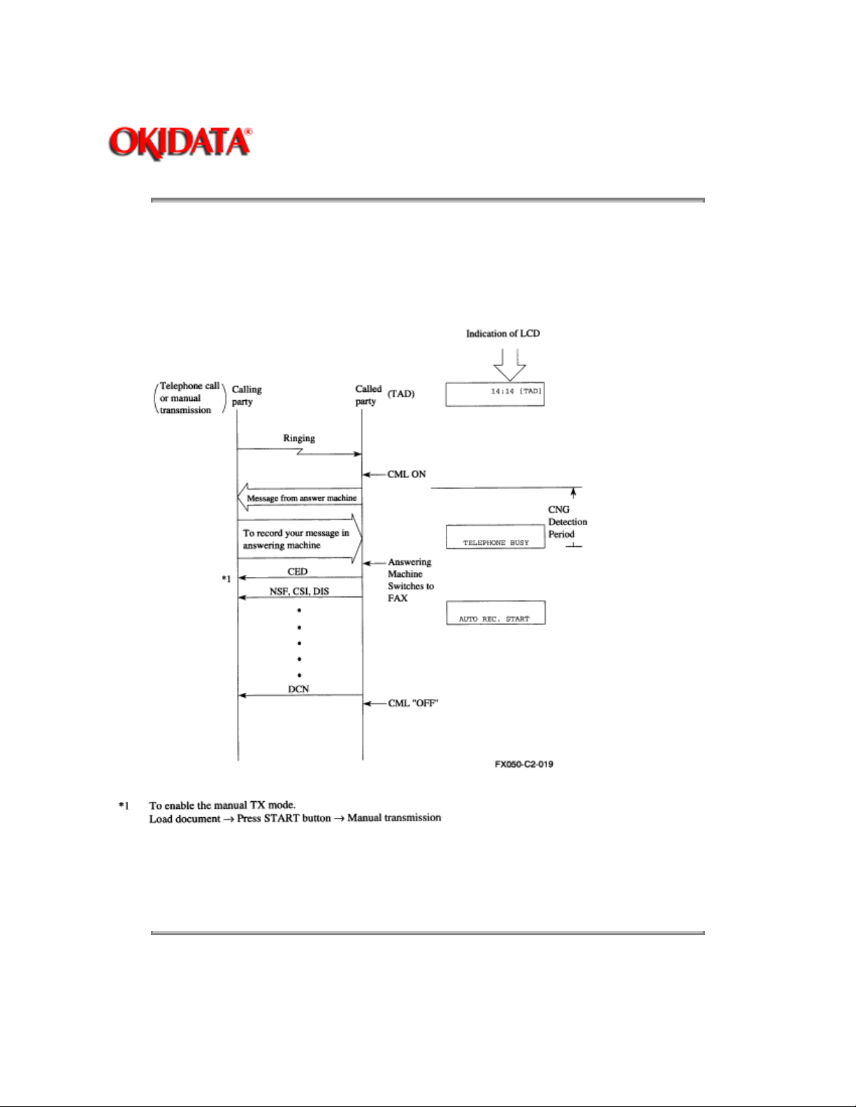
Service Guide OF1050/2350/2450
Chapter 2 Setup Information
TAD mode flow chart
- In case of TYPE 1;
Even though the fax does not detect CNG signal, the fax will go to receiving mode.
Page: 46
*1 To enable the manual TX mode.
Load document ---> Press
Copyright 1997, Okidata, Division of OKI America, Inc. All rights reserved. See the OKIDATA Business
Partner Exchange (BPX) for any updates to this material. (http://bpx.okidata.com)
START
button ---> Manual transmission
Page 100
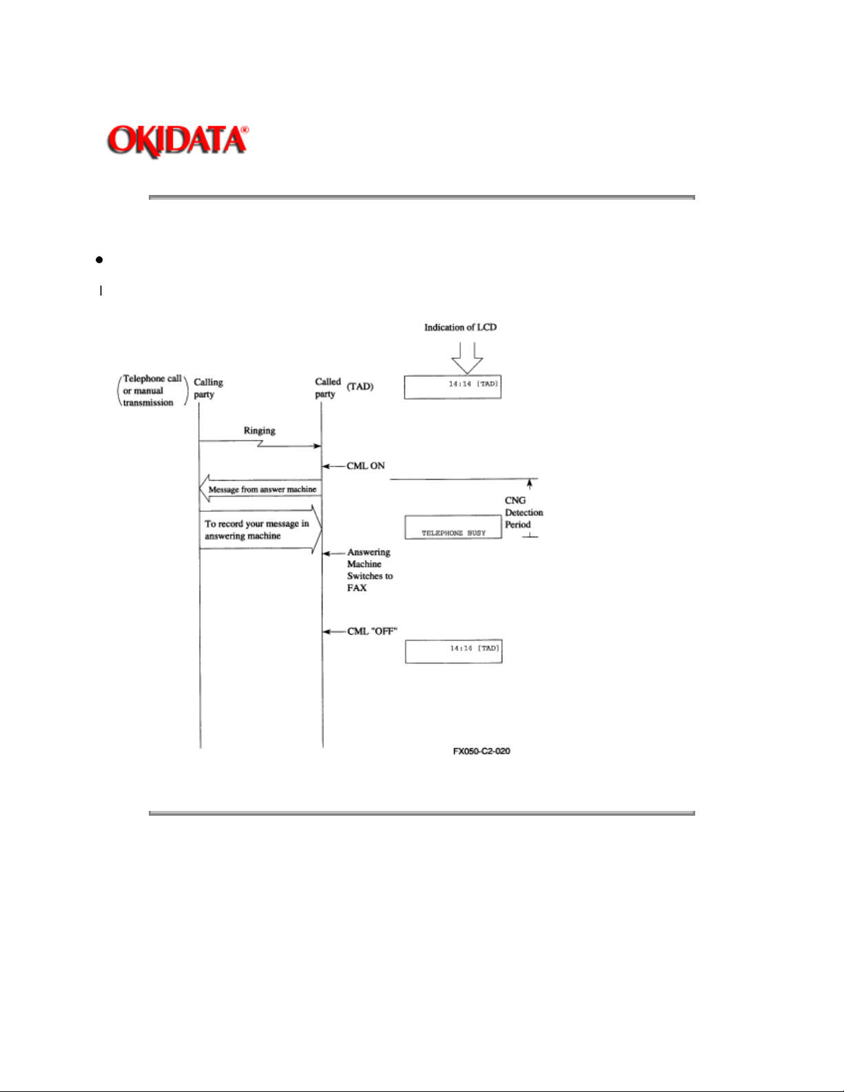
TAD mode flow chart
In case of TYPE 2:
Page: 47
Service Guide OF1050/2350/2450
Chapter 2 Setup Information
If the fax does not detect
CNG
signal during working of TAD, the machine will go to standby mode.
Copyright 1997, Okidata, Division of OKI America, Inc. All rights reserved. See the OKIDATA Business
Partner Exchange (BPX) for any updates to this material. (http://bpx.okidata.com)
 Loading...