

Page 1

C7000 Series
Color LED Page Printer
SERVICE MANUAL
OkiData
01-23-2001 based on Rev.4
41316401TH Rev.4A 1 / 186
Page 2

Document Revision History
Rev.No. Date
1
2000-05-29 ISSUE E4 Yamazaki
No.
Corrected items
Page Description of change
Person in
charge
2 2000-05-31 E4 Murakami
3 2000-12-04 NIP9 Yamazaki
4 2000-12-15 NIP9 Yamazaki
41316401TH Rev.4 2 /
Page 3

PREFACE
This manual describes the procedures for the maintenance of the C7000 Series of printers.
The document is produced for maintenance personnel use. For details on the procedures for handling the
C7000 Series of printers, see its user documentation.
Note!
• The descriptions in this manual are subject to change without prior notice.
• In preparing the document, efforts have been made to ensure that the information in it is accurate.
However, there may be errors in the document. Oki Data assumes no responsibility for any
damage resulting from, or claimed to be the results of, those repairs, adjustments or modifications to the printers which are made by users using the manual.
• The parts used for the printers are electrostatic sensitive and, if handled improperly, may be damaged.
It is strongly recommended that the products be maintained by Oki Data Authorized Repair Centers
Oki Data.
.
41316401TH Rev.4 3 /
Page 4

CONTENTS
1. CONFIGURATIONS ......................................................................................... 7
1.1 System Configuration....................................................................................................... 7
1.2 Printer Configuration ........................................................................................................8
1.3 Option Configuration ........................................................................................................ 9
1.4 Specifications................................................................................................................. 10
2. OPERATION DESCRIPTION ......................................................................... 12
2.1 Main Board (CRM PWB)................................................................................................ 13
13
2.2 Engine Controller Board (K71 PWB).............................................................................. 15
2.3 Power Units.................................................................................................................... 16
2.4 Mechanical Processes .................................................................................................. 17
2.4.1 Electrophotographic process............................................................................ 18
2.4.2 Paper running process ..................................................................................... 23
2.5 Sensor............................................................................................................................ 31
2.5.1 Paper related sensors ...................................................................................... 31
2.5.2 Other sensors................................................................................................... 32
2.6 Color Misalignment Correction....................................................................................... 33
2.7 Transfer Control Responds to Environmental Changes
(Room Temperatures and Relative Humidities)............................................................. 33
2.8 Paper Jam Detection ..................................................................................................... 34
2.9 Cover-Open ...................................................................................................................35
2.10 Toner Low Detection...................................................................................................... 36
2.11 Page Size Detection ...................................................................................................... 37
2.12 Operation at Power-on................................................................................................... 38
2.12.1 Self-diagnostic test........................................................................................... 38
2.13 Color Misalignment Detection ........................................................................................ 39
2.14 Version Read of Units Replaced Periodically ................................................................ 40
2.15 Life Count for Units Replaced Periodically..................................................................... 40
2.16 Toner Consumption Detection ...................................................................................... 40
3. PARTS REPLACEMENT................................................................................ 41
3.1 Precautions in Replacing Parts...................................................................................... 41
3.2 Parts layout .................................................................................................................... 43
3.3 Replacing Parts..............................................................................................................49
3.3.1 Top Cover......................................................................................................... 51
3.3.2 LED Assy/ LED Assy Spring............................................................................. 52
3.3.3 Top Cover Unit ................................................................................................. 53
3.3.4 Control Panel Assy/ Control Panel Bezel/ LED Control PWB/ Toner Sensors/
Stacker Full Sensor/ Control Panel/ Control Panel Tape Harness/ Eject Rollers. 54
3.3.5 Top Cover Handle/ Top Cover Latch/ Top Cover Latch Spring........................ 55
3.3.6 Eject Guide Assy .............................................................................................. 56
3.3.7 Cassette Assy/ Front Cover Assy/ Front Cover Inner Baffle ........................... 57
3.3.8 Retard Pad Assy/ Retard Pad Assy Spring ...................................................... 58
3.3.9 Feed Roller and Nudger Roller......................................................................... 59
3.3.10 Rear Cover....................................................................................................... 60
3.3.11 Face-Up Tray.................................................................................................... 61
3.3.12 Left Side Cover................................................................................................. 62
3.3.13 Right Side Cover .............................................................................................. 63
3.3.14 Multipurpose Tray Assy/ Multipurpose Tray Cover Assy/ Links/
Multipurpose Tray Top Cover/ Multipurpose Tray Drive Gear.......................... 64
3.3.15 Drum Contact Assys .......................................................................................... 65
3.3.16 Registration Roller Assy (A)/ Registration Drive Gear (A)................................ 66
3.3.17 Registration Roller Assy (B) ............................................................................. 67
3.3.18 Registration Clutch and Registration Motor Assy............................................. 68
3.3.19 Main Cooling Fan ............................................................................................. 69
41316401TH Rev.4 4 /
Page 5

3.3.20 Color Registration Sensor Assy........................................................................ 70
3.3.21 Duplex Guide Assy........................................................................................... 71
3.3.22 Electrical Chassis Cooling Fan......................................................................... 72
3.3.23 Printer Engine Controller PWB......................................................................... 73
3.3.24 Printer Unit Chassis.......................................................................................... 74
3.3.25 Entrance Cassette Sensor Actuator................................................................. 75
3.3.26 Entrance Sensor PWB...................................................................................... 76
3.3.27 Entrance MT Sensor Actuator and Entrance Belt Sensor Actuator.................. 77
3.3.28 Fuser Exit Roller............................................................................................... 78
3.3.29 Exit Sensor Assy .............................................................................................. 79
3.3.30 Fuser Latching Handle (L)................................................................................ 80
3.3.31 Belt Motor Assy ................................................................................................ 81
3.3.32 Fuser Latching Handle (R) ............................................................................... 82
3.3.33 Main Motor Assy............................................................................................... 83
3.3.34 Main Feeder Drive Motor.................................................................................. 84
3.3.35 Contact Assy/ Left Plate Assy .......................................................................... 85
3.3.36 Low Voltage Power Supply............................................................................... 86
3.3.37 High voltage power supply ............................................................................... 87
3.3.38 Main Feed Assy................................................................................................ 88
3.3.39 Cassette/ Left Guide Assy................................................................................ 89
3.3.40 Cassette/ Right Guide Assy.............................................................................. 90
3.3.41 Fuser Unit......................................................................................................... 91
3.3.42 Belt Unit............................................................................................................ 92
3.3.43 Duplex Unit....................................................................................................... 93
3.3.44 Guide Rails (L) and (R)..................................................................................... 94
3.3.45 Duplex Transport Assembly ............................................................................. 95
3.3.46 CU Assy............................................................................................................ 97
4. ADJUSTMENTS ............................................................................................. 99
4.1 Maintenance Modes and Their Functions...................................................................... 99
4.1.1 Maintenance menu........................................................................................... 99
4.1.2 Engine maintenance mode............................................................................. 100
4.1.2.1 Operator panel................................................................................... 100
4.1.2.2 General self-diagnosis mode (level 1)............................................. 100
4.1.2.2.1 Entering self-diagnosis mode (level 1) ............................ 100
4.1.2.2.2 Exiting self-diagnosis mode ............................................ 100
4.1.2.3 Switch scan test................................................................................. 101
4.1.2.4 Motor and clutch test ......................................................................... 104
4.1.2.5 Test printing .................................................................................... 106
4.1.2.6 NVM initialization............................................................................ 110
4.1.2.7 Consumable counter display........................................................... 111
4.1.2.8 Consumable counter display - continuous ...................................... 111
4.1.2.9 Error Messages and their Details.................................................... 112
4.1.3 CRM board adjustments................................................................................. 116
4.1.3.1 Short plug settings .......................................................................... 117
4.1.3.2 Printings singly using controller-equipped printer ........................... 117
4.2 Adjustments after Parts Replacement ......................................................................... 118
4.2.1 Precautions in replacing engine controller board ........................................... 118
4.2.2 Precautions in replacing EEPROM................................................................. 118
4.2.3 EEPROM replacement after CRM board replacement................................... 119
4.3 Color Balance Adjustment ........................................................................................... 120
5. PERIODIC MAINTENANCE ......................................................................... 122
5.1 Parts Replaced Periodically ......................................................................................... 122
5.2 Cleaning....................................................................................................................... 122
5.3 Cleaning LED Lens Array ............................................................................................ 122
5.4 Cleaning Pickup Roller................................................................................................. 122
41316401TH Rev.4 5 /
Page 6

6. TROUBLESHOOTING PROCEDURES ....................................................... 123
6.1 Before Troubleshooting................................................................................................ 123
6.2 Checking before Troubleshooting Image Problems..................................................... 123
6.3 Precautions in Troubleshooting Image Problems ........................................................ 123
6.4 Preparation for Troubleshooting .................................................................................. 123
6.5 Troubleshooting ........................................................................................................... 123
6.5.1 LCD messages list.......................................................................................... 124
6.5.2 Preparation for troubleshooting ...................................................................... 129
6.5.3 Troubleshooting image problems ................................................................... 140
7. CONNECTION DIAGRAM............................................................................154
7.1 Resistance Checks ...................................................................................................... 154
7.2 Program/Font ROM Layouts ........................................................................................ 158
8. Parts List......................................................................................................162
APPENDIX A CENTRONICS PARALLEL INTERFACE................................... 178
APPENDIX B 2ND/3RD TRAY MAINTENANCE .............................................. 182
41316401TH Rev.4 6 /
Page 7
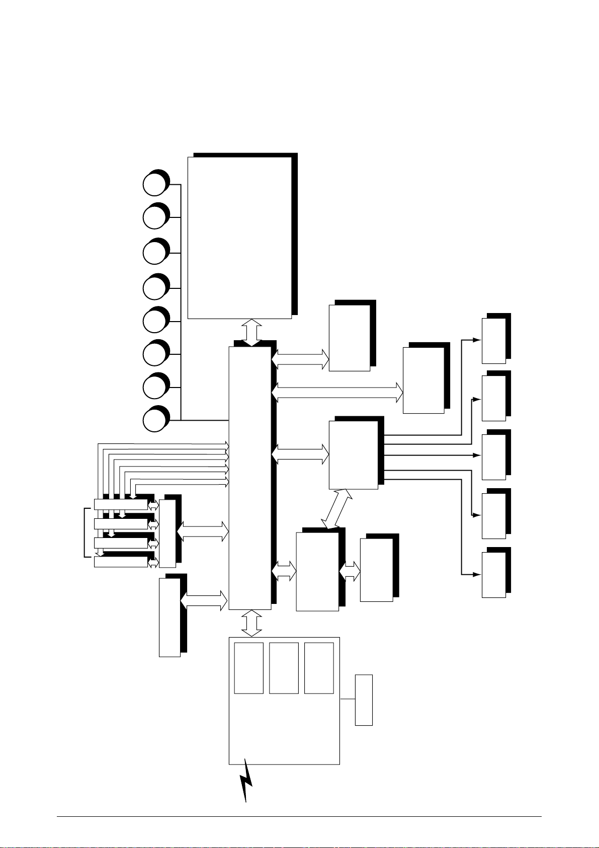
M
M
M
M
M
M
M
M
LED Head
Centronics I/F
USB I/F
2 × Option Slots
Junction Board
Pulse Motor
Engine Control
Low V oltage
Power Unit
Fuser
Unit
High V oltage
Power Unit
2nd/3rd T ra y
Duplex
Unit
Belt
Unit
<Sensors, Switches and Thermistors>
Paper size sensor (4 bits)
Paper empty sensor
Paper near empty sensor
MT paper empty sensor
FF home switch
Loading sensor 1
Loading sensor 2
C-ID
Unit
M-ID
Unit
Y-ID
Unit
K-ID
Unit
C ID M ID Y ID K IDBelt Heat
MT/
Registration
Hopping
Operator Panel
3 × ROM
DIMMs
4 × RAM
DIMM
IDE
I/F(HDD)
DC Fan
Note
Note Option Slot:
LAN Card made by JCI
1. CONFIGURATIONS
1.1 System Configuration
Figure 1-1 shows the system configuration of the C7000 Series of printers.
Figure 1-1
41316401TH Rev.4 7 /
Page 8
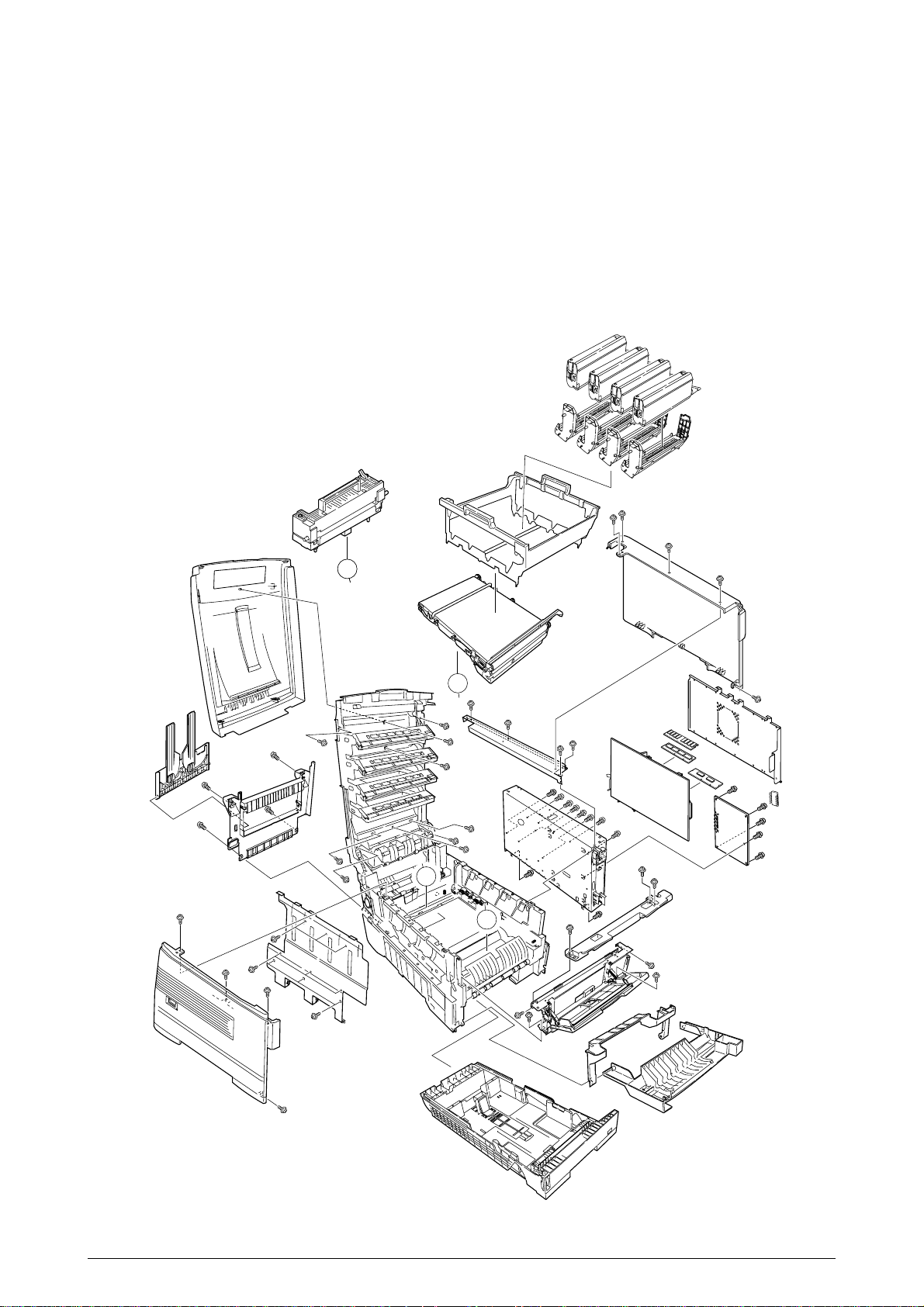
1.2 Printer Configuration
The inside of the printers is composed of the followings:
• Electrophotographic Processor
• Paper Paths
• Controller Block (CU and PU)
• Operator Panel
• Power Units (High Voltage Unit and Low Voltage Unit)
Figure 1-2 shows the printer configuration.
B
B
A
B
B
A
A
Figure 1-2
41316401TH Rev.4 8 /
Page 9
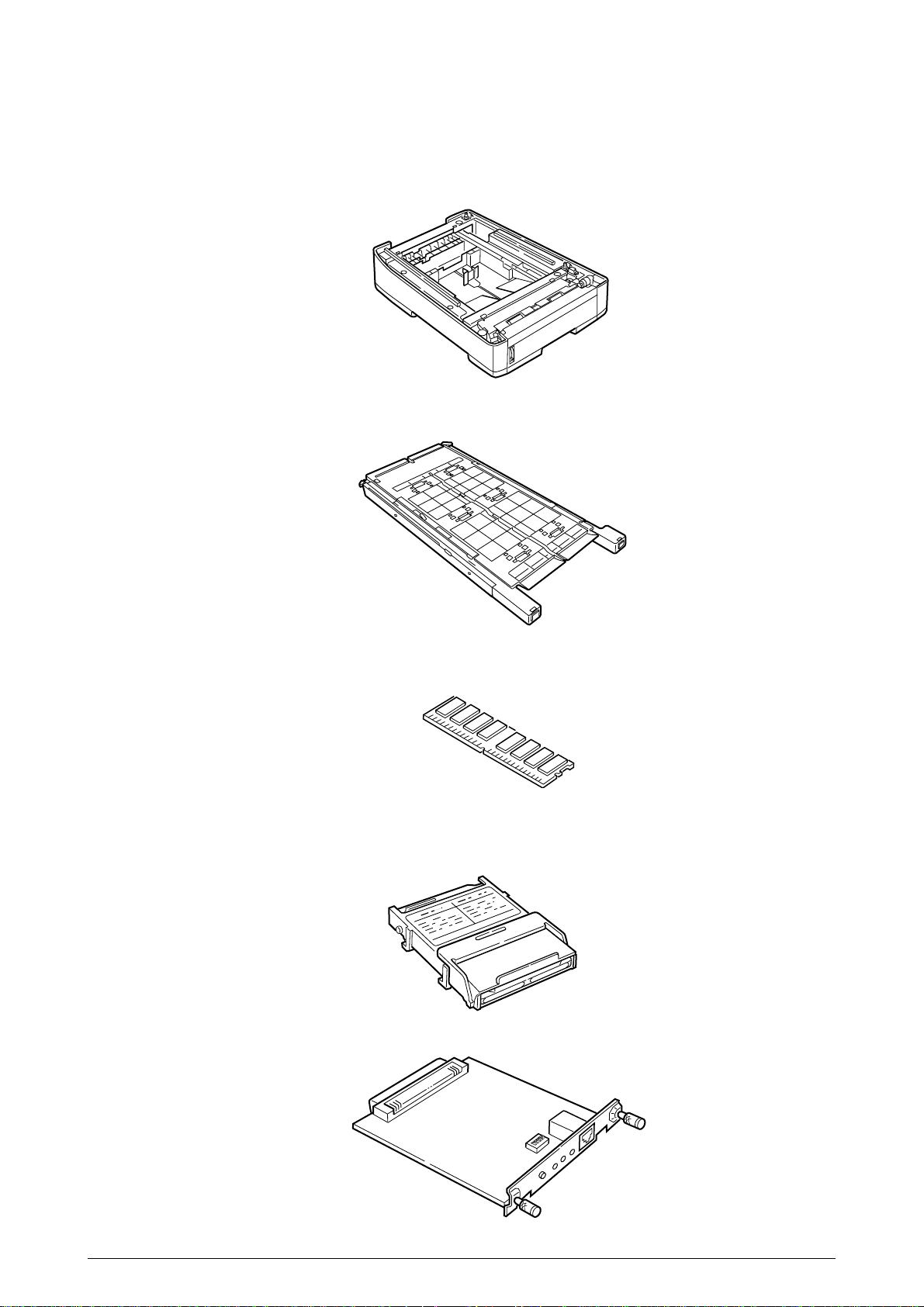
1.3 Option Configuration
The following options are available for the C7000 Series of printers.
(1) 2nd Tray/ 3rd Tray
(2) Duplex Unit
(3) Expansion Memory 64/128/256 MB
(4) Internal Hard Disk
(5) OkiLAN 6200e NIC
41316401TH Rev.4 9 /
Page 10

1.4 Specifications
(1) External Dimensions Height: 16.9 in. Width: 16.9 in. Length: 24.4 in.
(2) Weight 92.5 lbs.
(3) Papers Type: Ordinary paper, Transparencies (Recommended: MLOHP01)
(4) Print Speed Color: 12 pages per minute (Transparency: 5 pages per minute)
(5) Resolution (C7200) = 600 × 600 -//- (C7400) 1200 x 1200 dots per inch
(6) Power Input 100VAC ±10%
(7) Power Consumption Peak:1300W Normal Operation: 400W (5% duty)
Size: Postal card, Legal 13" or 14", Executive, A4, A5, B5, A6 (Only
the 1st tray and the front feeder support A6 and postal-card
sizes.)
Weight:1st tray55 kg to 90 kg (64 to 105g/m2)
Front feeder55 kg to 140 kg (64 to 163g/ m2)
Monochrome: 20 pages per minute (Transparency: 12 pages per minute)
Postal Card, Label, Thick Paper: 8 pages per minute
Idle: 110W Power Saving Mode:45W or less
(8) Frequency 50Hz or 60Hz ±2%
(9) Noise Operation: 54 dB (Without second tray)
Standby: 45 dB
Power Saving:43 dB
(10) Consumable Life Toner Cartridge: 10,000 pages (5% duty) (each of Y, M, C and K)
Image Drum: 30,000 pages (Continuous printing)
(each of Y, M, C and K)
(11) Parts Replaced Periodically Fuser Unit Assy: Every 60,000 pages
Transfer Belt Assy: Equivalent of 60,000 pages (3 pages/job)
41316401TH Rev.4 10 /
Page 11
(12) Temperatures and Relative Humidities
Temperature
Temperature Condition
Temperature (˚F) Temperature (˚C) Remark
Operation 50 to 89.6 10 to 32 17 to 27˚C
(Temperatures to assure full
color print quality)
Non-Operation 32 to 109.4 0 to 43 Power-off
Storage (Max. One Year) -14 to 109.4 -10 to 43 With drum and toner
Transport (Max. One Month) -20 to 122 -29 to 50 With drum and without toner
Transport (Max. One Month) -20 to 122 -29 to 50 With drum and toner
Humidity
Humidity Condition
Relative Humidity Max. Wet-Bulb Remark
(%) Temperature(˚C)
Operation 20 to 80 25 50 to 70% (Humidities to assure full
color print quality)
Non-Operation 10 to 90 26.8 Power-off
Storage 10 to 90 35
Transport 10 to 90 40
(13) Printer Life 600,000 pages (on a A4-size basis) or five years
41316401TH Rev.4 11 /
Page 12
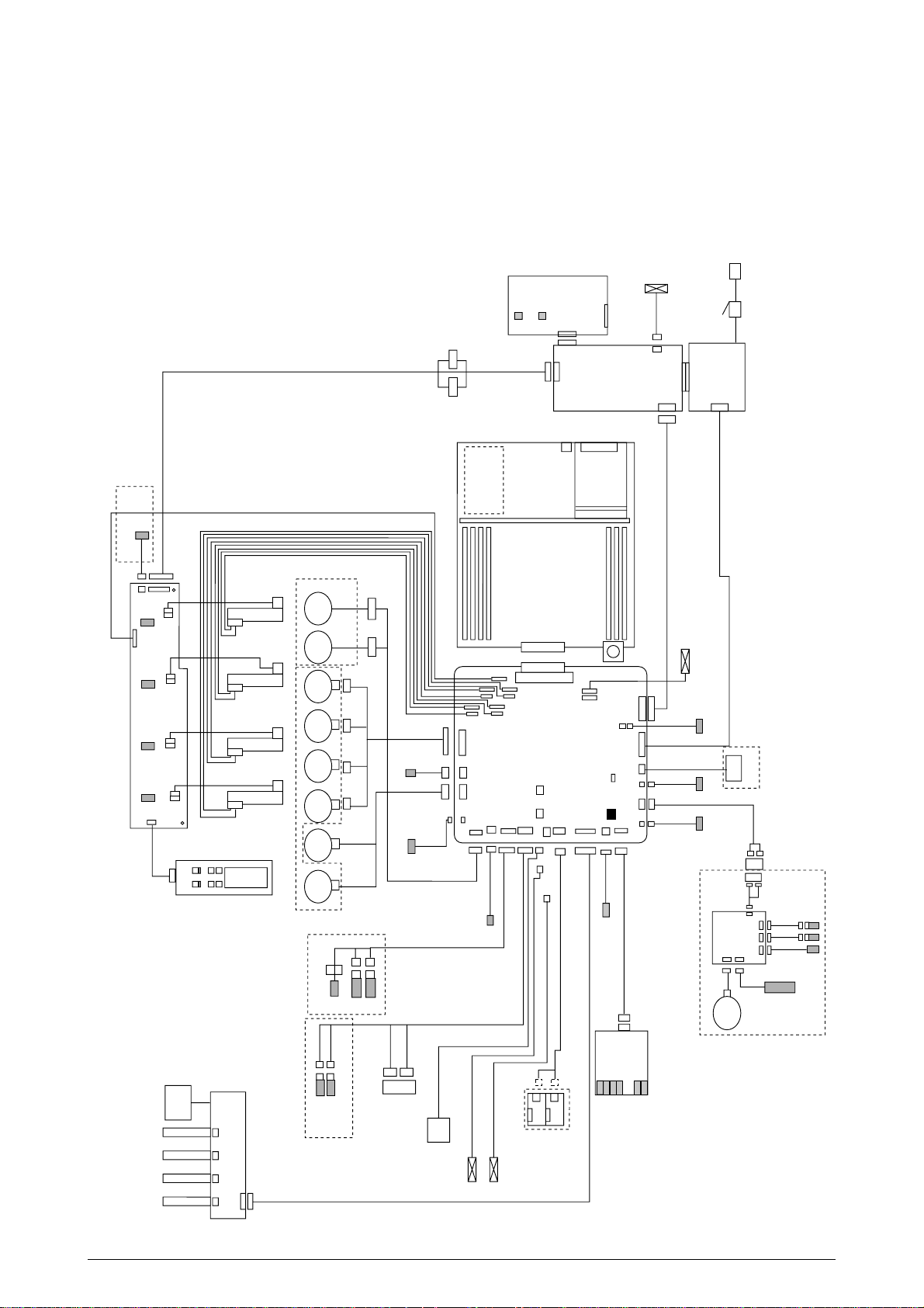
2. OPERATION DESCRIPTION
N71 Board
Belt
Fuse
K Fuse
Y Fuse
M Fuse
C Fuse
JODEN
14P
Paper Tray 1 Paper Empty
Paper Tray 2 Near Empty
3P
3P
WHITE
BLUE
OPTION
7P
7P
BLUE
BLUE
BLUE
WHITE
WHITE
WHITE
RED
9P
10P 14P 14P
4P
3P
22P
11P 2P
8P
YELLOW
YELLOW
FAN1 (Pr)
HUM/
TMP
3P
FAN2 (Pow)
Plate Senosr
Gray
Blue
Z7L
Z7R
9P
R71 Board
Manual Bypass Feeder (MBF)
Hopping
Motor
FF/Regist
Motor
K IDU
Motor
Y IDU
Motor
M IDU
Motor
C IDU
Motor
Belt
Motor
Heat
Motor
MBF Stage
MBF Paper Empty
Duplex Unit
DUP
V71 Board
Motor
Clutch
INSENS
FSENS
RSENS
Main
14P
7P
7P
7P
7P
Front Cover
Open
Microswitch
Duplex Cover
Open Microswitch
Upper Cover
Open Microswitch
COVOPN
71K Board
POWER
FAN
FAN(LEFT)
3P
HVOLT
CPUFL1
PSIZE
DUCOV
FCOVER
DUPLEX
PARTTEMP
JODEN
RSNS
SW1
FSENS
FAN1
HUM/TMP
FAN2
CUIF
FAN4
Cord 18
Cord 19
BLACK
Exit Sns.
WHITE
REG
DCL
BELTHET
TR10P
SHUTTER
HOPFF
RCL ID
CLUTCH3
Main Motor Assy Belt Motor Assy
46
WHITE YELLOW
K LED HEAD
Control Panel
X71 board
Y LED HEAD
M LED HEAD
C LED HEAD
Toner Sensor (Y71-board)
Paper Size
Sensor
PXC-Board
AC Switch
AC
CN1 CN1
CN5
CN2
High -Voltage
Power Supply
Low-Voltage
Power Supply
CN3
CN2
16P
30P
30P
19P6P3P
16P
3P
19P
2P
8P 2P 16P
Cord 20
Cord 7
6P
TNRK
PANEL
STUCK
POWER
4P 4P
4P 4P 4P 4P
RED WHITE
BLACK YELLOW RED BLUE
6P
KPOW2
TNRY
YPOW2
TNRM
MPOW2
TNRC
CPOW2
OPTN
16P
3P
3P
3P3P3P
16P
STUCKFULL
Sns.
RED
RED
BLACK
BLACK
88
THERM1
THERM2
FUSE
NFU
3P
FAN0
Up/Down
OHP Sen.
2
RAM
CRM Board
ROM
HDD
LAN
USB
CENTRO
The C7000 Series of printers, tandem color electrophotographic page printers, adopt technologies
such as an LED array, OPC, dry single-component non-magnetic developing, roller transfer and
heat-compression fusing. A black-writing printing method by shedding light on print areas is used.
41316401TH Rev.4 12 /
Figure 2-1 provides the block diagram of the printers.
Figure 2-1
Page 13
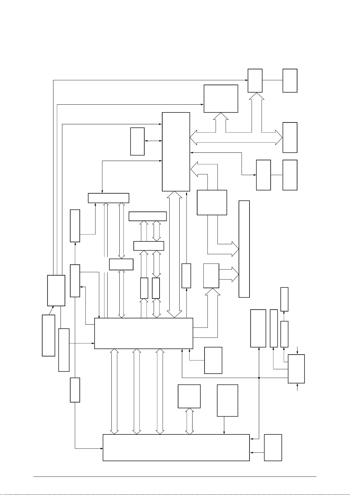
2.1 Main Board (CRM PWB)
14.31818MHz
Crystal Resonator
CY2292
CY2308Delay CDC516
SDRAM DIMM
×
4
ROM DIMM
×
3
FET SW
162212
Flash ROM
IMI530
Fluctuation Circuit
LVC244
LVC245
EEPROM
C2 LSI
MHM2031-002
PCI Bus
LAN Board
L60851
USBCentro IDE HDD
LVC161284
Buf
16244
Buf
16244
Delay
PU Board Connector, 200 Pins
to C2 LSI and
3.3V ICs
to 5V ICs
Inverter RESET-P
3.3V5V
Reset
DS1834
2.0V
Regulator
2.5V
Regulator
C1 LSI
MHM2030
-002
PPC
750
L2
Cache
Internal-CLK-
Adjusting
Resistance
80MHz
80MHz
80MHz
40MHz
80MHz
×
2
80MHz
×
16
33MHz
~
2
48MHz
IF Bus
33MHz
SPD
PU-CU I/F,
Operator Panel
A/D, Cont (SUB Bus)
Y, M, C and K Video Data
D
D
A
D
Cont
D
DD
A, Cont A, Cont A, Cont
A, Cont
A/D, Cont
Figure 2-2 provides the block diagram of the main control board (CRM PWB).
Figure 2-2
41316401TH Rev.4 13 /
Page 14

(1) CPU
The CPU is PowerPC750, a 64-bit bus RISC processor, which inputs an 80-MHz CLK (= BUS
CLK), and operates at 400MHz that is five times the input.
(2) Secondary Cache SRAM
SRAM is included as secondary cache of the CPU on the board.
(3) ROM
ROM is to be inserted into the three 168 pin DIMM slots. The slot A is for program ROM and
the slot B is for Japanese kanji fonts. The slot C is not assigned.
(4) RAM
RAM is to be inserted into the four 168 pin DIMM slots. The DIMMs must be fitted in
descending labeled type No. order into the slots 1, 3, 2 and 4.
SDRAM DIMM Specifications:
Speed: PC100 or more
Capacity: 64/128/256 MB
Configuration: Without parity. Without ECC. SPD information is required. Number
of chips contained = 8 or 16.
(5) EEPROM
EEPROM, an 8-pin DIP package, is to be inserted into the IC socket. The EEPROM is of 16
Kbits for 3.3V power supply, and settings for controlling the controller block are stored in it.
(6) Flash ROM
A 2-Mbyte flash ROM is surface-mounted on the CRM board. The flash ROM is composed
of four 256-k-by-16bit chips, and fonts and macros can be stored in it.
(7) Memory Control LSI (CI)
A 696-pin BGA package ASIC made by NEC, which is equipped with a cooling heat sink and
mainly controls a CPU I/F, memory, video data compression and decompression, and a PUvideo I/F.
(8) Interface Control LSI (C2)
A BGA package ASIC made by Toshiba, which controls a PU command I/F, operator panel
I/F, IDE I/F, Centronics I/F, USB I/F, PCI I/F, EEPROM and a SPD (SDRAM DIMM) I/F.
(9) IDE HDD
An IDE connector is surface-mounted on the board to which an IDE HDD assembled using
exclusive molds will be connected. The IDE HDD is used for storing font data, spooling edited
video data and registering form data.
(10) PCI Bus Option
Two PCI I/F slots are provided for option board use. The bus, which uses an Oki Data original
connector, can accept an Ethernet board.
(11) Host Interface
Standard: Centronics two-way parallel I/F (IEEE-1284-compliant)
USB (USB1.1-compliant)
Additional Board: (connected to PCI BUS)
Ethernet Board
41316401TH Rev.4 14 /
Page 15
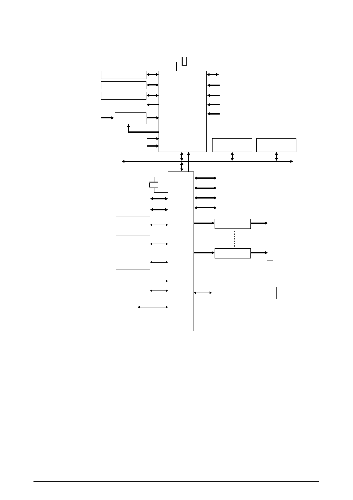
2.2 Engine Controller Board (K71 PWB)
28MHz
(Color registration sensor adjustment)
Analog input
(Temperature variation)
Analog input (Transparencies)
Analog input (Various densities)
CPU BUS
Toner and ID sensors ID checks
Control Panel
Duplex
Cassette 2/3
Analog output
Analog Input
Switch
48MHz
32bit Video I/F
Heater control
Fuse Cut
Driver
EEPROM
D/A
CU I/F
CPU
MSM66Q577
A/D CON
LSI
(VIDEO MEM
Containing
4Mbit DRAM)
Fan control
Cover front/upper open
Stacker full
Test switch
(Power supply cooling)
4Kbit(512KByte)
FLASH
Interruption by motor
Interruption by UART
K Head I/F
Y Head I/F
M Head I/F
C Head I/F
Motor Driver
Motor Driver
High Voltage Power Supply
Serial Interface (2 channels)
256Kbit(32KByte)
SRAM
×
Pulse Motors
8
Paper Feed System Sensors
(Paper Feed, Paper Registration,
Write and Eject Sensors)
MT Sensor (Stage position and paper empty)
Cassette 1 Sensor
(Paper empty and near empty)
Any of Shutter, Clutch, Belt Home and
Transparency Sensors
Belt and Fuser Checks
Cassette Size
Figure 2-3
The engine control block (PU) is controlled by the engine controller board (K71 PWB) which
consists of a CPU (MSM66Q577), general LSI chip, flash ROM, EEPROM, pulse motor drivers and
a video memory (see Figure 2-4).
(1) CPU
This, a 16-bit CPU with an AD converter containing 126-Kbyte ROM (OKI MSM66Q577),
controls the entire system.
(2) General LSI
This LSI (MG63P011-001LA), which is contained in the printer engine control block, has 4
Mbits of video memory, and functions such as controller-engine video interfacing, LED
interfacing, motor control, sensor input, video memory control, main scan color misalignment
correction, skew correction and high voltage power supply control.
41316401TH Rev.4 15 /
Page 16

(3) Flash ROM
The flash ROM (29F400-70) is of 4-Mbits, and PU programs are stored in it.
(4) EEPROM
The EEPROM (NM93C66N-NW) is of 4-Kbits, and mounted on the board with an IC socket.
Correction values are stored in it.
(5) Pulse Motor Driver
The pulse motor driver (A2919SLBTR, A2918SWV) drives the eight pulse motors to revolve
the EP and transport media.
(6) SRAM
This SRAM (62256LFP-7LL) is used as working memory of the CPU.
2.3 Power Units
There are a low voltage power unit consists of an AC filter circuit, low voltage power circuit and
heater driver circuit, and a high voltage power unit organizes a high voltage power circuit.
(1) Low Voltage Power Unit
This circuit generates the following voltages:
Output Voltage Use for
+3.8V CU LSI
+3.8V LED head
+5 V Logic circuit power supply, PU CPU
+34 V Motor, drive voltage and power supply voltage for high voltage power supply
+12 V OP Amp, High voltage power supply
(2) High Voltage Power Unit
This circuit generates the following voltages of not less than +34V, which are required for
electrophotographic process, according to control sequences from the controller board.
Output Voltage Use for Remark
CH -900V to 1.4KV Voltage to charging roller
DB -100 to 400V/ +300V Voltage to developing roller
SB Y, M, C and K: -100V to -700V Voltage to toner supplying roller
TR 0KV to 7KV Voltage to transfer roller Variable
41316401TH Rev.4 16 /
Page 17
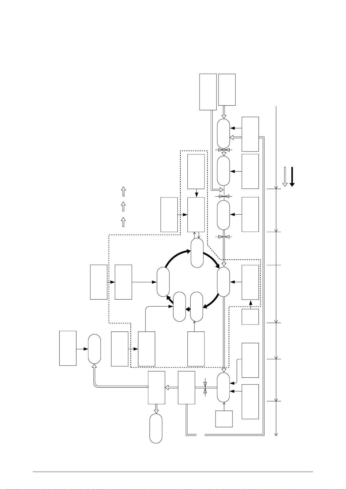
2.4 Mechanical Processes
Paper Eject Roller
Pape
ejection
(Face down)
Power Supply
Charging Roller
Cleaning Blade
Heat Roller
Paper
Eject
Roller
Fusing
Backup Roller
Control Signals
LED Head
Developing Roller
Power Supply
Toner Cartridge
Transfer Roller
Paper
registration
Registration
Roller 1
Paper loading
Hopping Roller
Power
Supply
Registration
Roller 2
Paper ejection Fusing Cleaning Transfer
Paper transport Paper advance
Transfer
Development
Paper Eject
Sensor
Paper Feed
Sensor 1
Paper Feed
Sensor 2
Paper Cassette
Paper
registration
(FF, 1ST, 2ND)
Write Sensor
×
4
K
YMC
Duplex printing
Paper path
selection
Paper path
selection
Paper traveling
OPC drum revolution
Charging
Exposure
Cleaning
Paper
ejection
(Face up)
Multipurpose Tray
Figure 2-4 shows the mechanical processes of the C7000 Series of printers.
41316401TH Rev.4 17 /
Figure 2-4
Page 18

2.4.1 Electrophotographic process
(1) Electrophotographic process
The following is the outline of electrophotographic process:
1 Charging
DC voltage is applied to the charging roller and the surface of the OPC drum is negatively
and evenly charged.
2 Exposure
The LED head, under image signals, emits light to the negatively charged surface of the
OPC drum. The radiated portions of the drum surface attenuate in negative charge
according to the intensity of the light and, based on the surface potentials, a latent
electrostatic image is formed on the drum surface.
3 Development
Negatively charged toner contacts the OPC drum and by electrostatic force adheres to
the latent electrostatic image to form a clear image on the drum surface.
4 Transfer
Placed on the surface of the OPC drum, paper is positively, or opposite to the polarity of
the toner, charged by the transfer roller on its back to transfer the toner image to the paper.
5 Cleaning
The cleaning blade removes residual toner from the OPC drum after the transfer.
6 Fusing
The toner image on the paper is fused into place through the application of heat and
pressure to it.
41316401TH Rev.4 18 /
Page 19
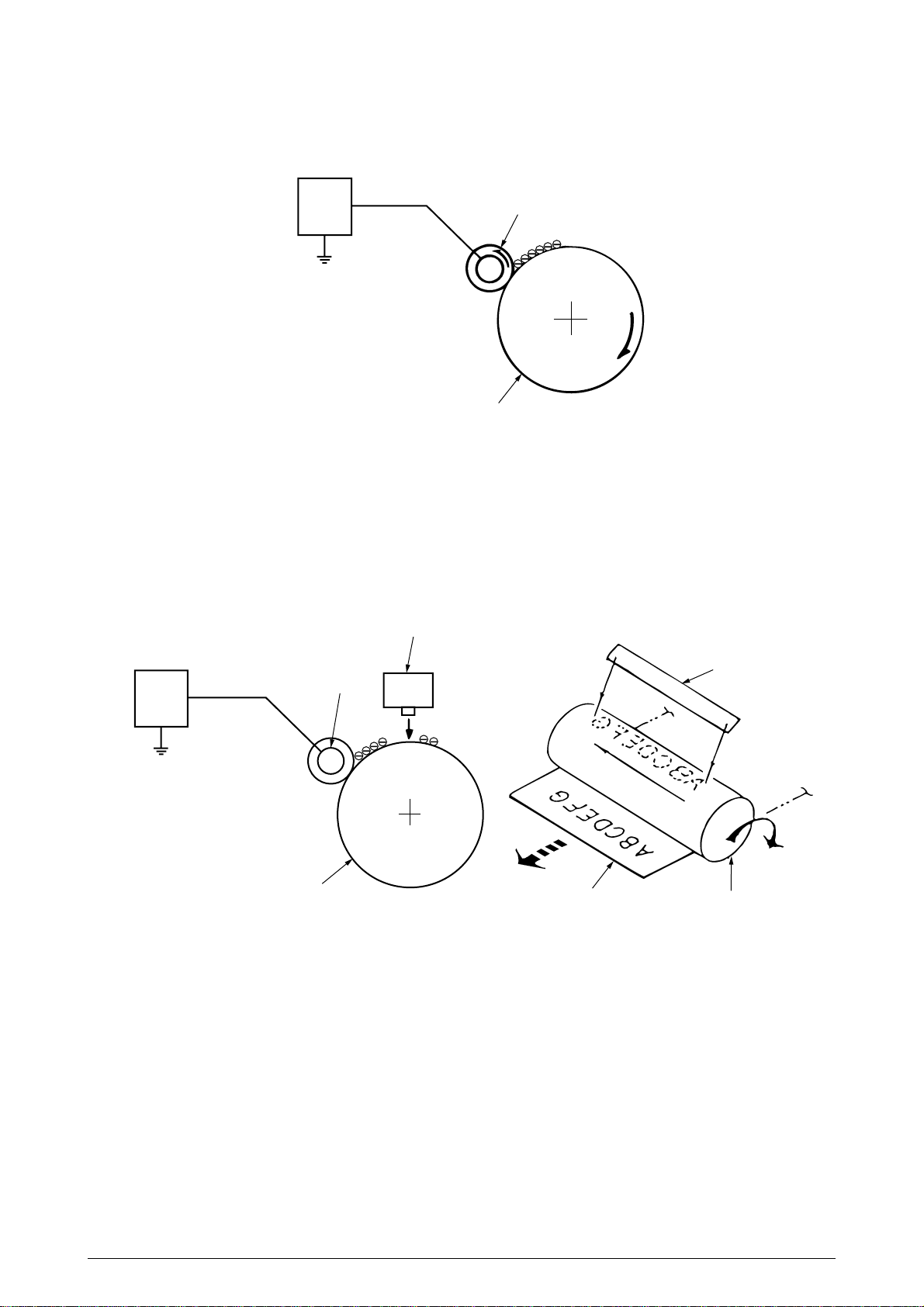
(2) Charging
Negative DC voltage is applied to the charging roller contacting the surface of the OPC drum.
Power
unit
Charging roller
OPC drum
(3) Exposure
The negatively charged surface of the OPC drum is radiated with light from the LED head.
The negative charge of the radiated portions of the drum surface attenuates in response to
the intensity of the light and a latent electrostatic image responsive to the potentials of the
surface is formed on the drum surface.
LED head
Power
unit
Charging roller
OPC drum
Paper
LED head
OPC drum
41316401TH Rev.4 19 /
Page 20
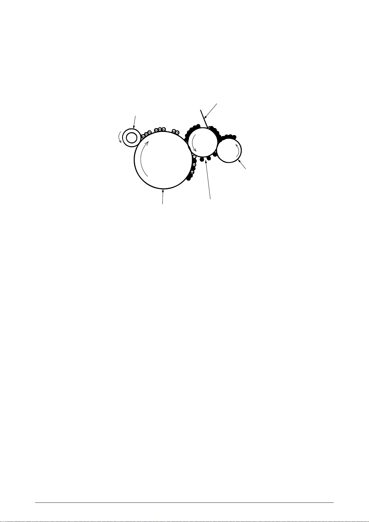
(4) Development
By the adhesion of toner to the latent electrostatic image on the drum surface, the image is
changed to an image of its toner. The development is processed at the contact portion
between the OPC drum and the developing roller.
1 The sponge roller causes toner to adhere to the developing roller. The toner becomes
negatively charged.
Developing blade
Charging roller
Sponge roller
OPC drum
Developing roller
2 The developing blade removes excess toner from the developing roller and a thin layer
of toner remains and forms on the developing roller.
3 The toner is drawn by the latent electrostatic image at the contact portion between the
OPC drum and the developing roller.
The latent electrostatic image on the drum surface is made visible with the toner.
41316401TH Rev.4 20 /
Page 21
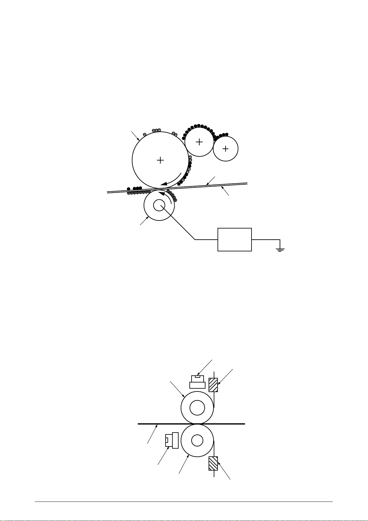
(5) Transfer
The transfer roller, which is made of conductive sponge, presses paper against the surface
of the OPC drum and brings the paper into intimate contact with the drum surface.
The paper is placed on the drum surface, and positively (opposite to the charge of the toner)
charged by the transfer roller on its back.
Applying positive high voltage from the power supply to the transfer roller moves the positive
charge induced by the transfer roller to the paper surface at the contact portion between the
transfer roller and the paper, the paper surface drawing the negatively charged toner from the
drum surface.
OPC drum
Paper
Transport belt
Transfer roller
Power unit
(6) Fusing
When passing through between the heat roller and the backup roller, the toner image
transferred to the paper is fused into place by the application of heat and pressure to it.
The built-in upper and lower halogen lamps of 700 watts and 500 watts heat the Teflon coated
heat roller. The fusing temperature is controlled by the sum of the temperature detected by
the thermistor moving over the heat roller surface and the temperature detected by the
thermistor moving over the backup roller surface. For safety, a thermostat is provided and,
when the heat roller temperature rises by a fixed degree or more, becomes open to cut off
voltage supply to the heater. The backup roller is being pressed against the heater by the
pressure springs on both sides.
Thermostat
Thermistor
Heat roller
Paper
Thermostat
Backup roller
41316401TH Rev.4 21 /
Thermistor
Page 22
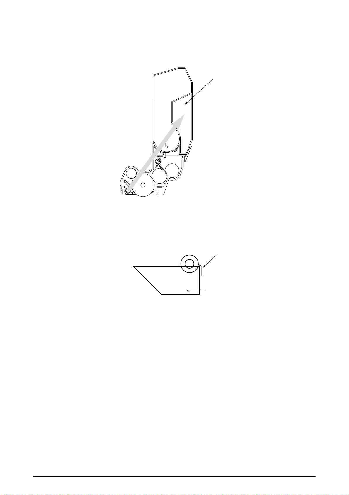
(7) Cleaning
Non-fused, residual toner on the OPC drum is scraped with the cleaning blade and collected
in the waste toner area of the toner cartridge.
Waste toner area
(8) Cleaning
Residual toner on the transfer belt is scraped with the cleaning blade and collected in the
waste toner box of the transfer belt unit.
Cleaning blade
Waste toner box
41316401TH Rev.4 22 /
Page 23
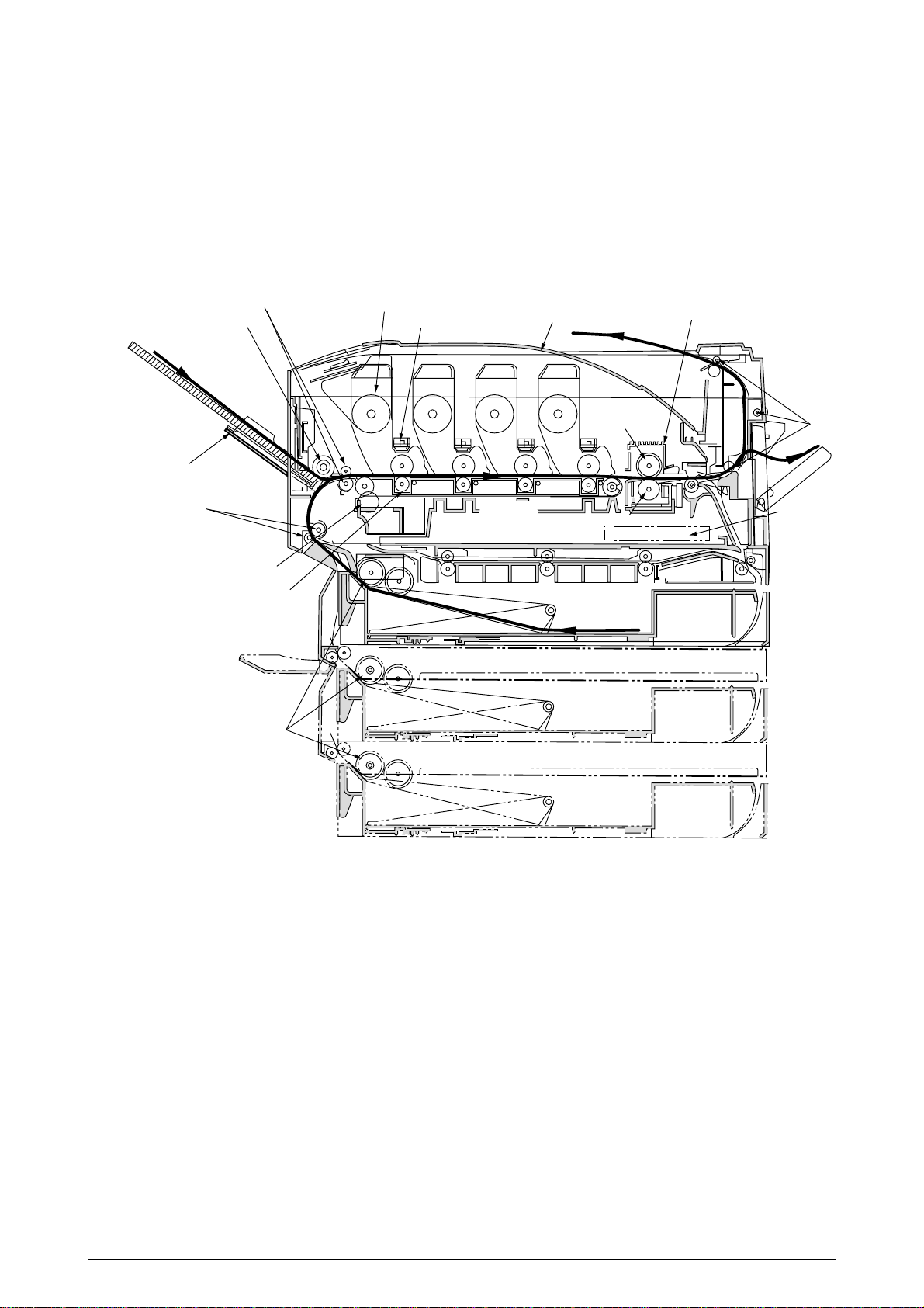
2.4.2 Paper running process
Figure 2-5 shows the traveling of paper in the C7000 Series of printers.
Registration roller Assy (B)
Hopping roller
Multipurpose tray
Registration roller Assy (A)
Cleaning blade
Transfer roller ×4
Feed roller
Unit × 4
Head × 4
High voltage power supply
Face-down stacker
MYK
Belt unit
Heat roller
C
Backup roller
Cassette 1
Cassette 2
Fuser
Eject roller
Low voltage
power supply
Figure 2-5 Paper Paths
Cassette 3
41316401TH Rev.4 23 /
Page 24
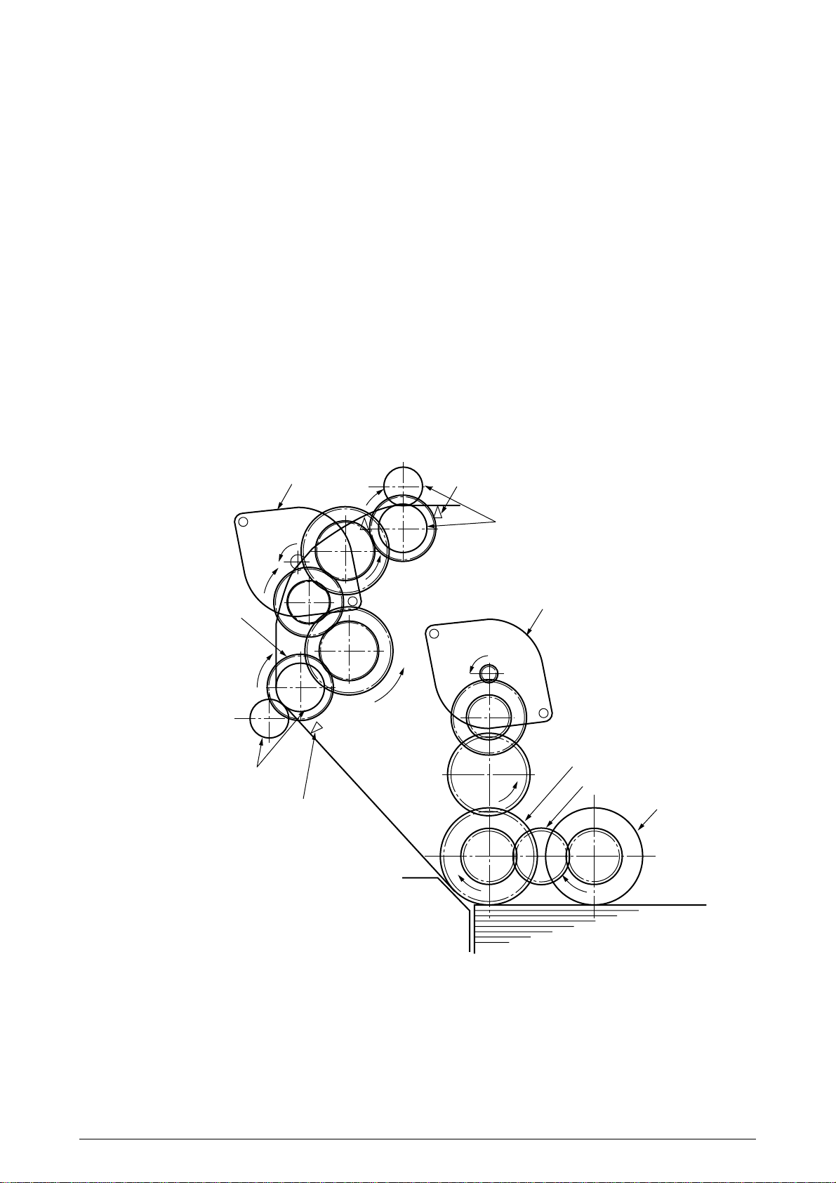
(1) Paper Feed from Tray
1. The running of the feed motor in the arrow direction (a) drives the feed roller and the nudger
roller. This operation feeds paper from the tray.
2. After the beginning of the paper turns the entrance cassette sensor on, the paper is
advanced a fixed length. When the paper beginning reaches the registration roller Assy
(A), the feed motor stops.
3. The running of the registration motor in the arrow direction (b), which synchronizes with
the above paper advance operation, drives the registration roller Assy (B) and the
electromagnetic clutch. The registration roller Assy (A) moves with the operation of the
electromagnetic gear when the paper beginning touches the registration roller Assy (A),
where the feed motor does not run. The feed roller idles via the built-in one-way clutch
and the nudger roller idles because the planet gear is disengaged.
4. The registration motor transports the paper until the paper end passes through the
entrance belt sensor.
Registration motor
Electromagnetic clutch
Registration roller
Assy (A)
Entrance cassette sensor
Entrance belt sensor
Registration roller
b
Assy (B)
Feed motor
a
Feed roller
(One-way clutch gear)
Paper gear
Nudger roller
Paper
Figure 2-6
41316401TH Rev.4 24 /
Page 25
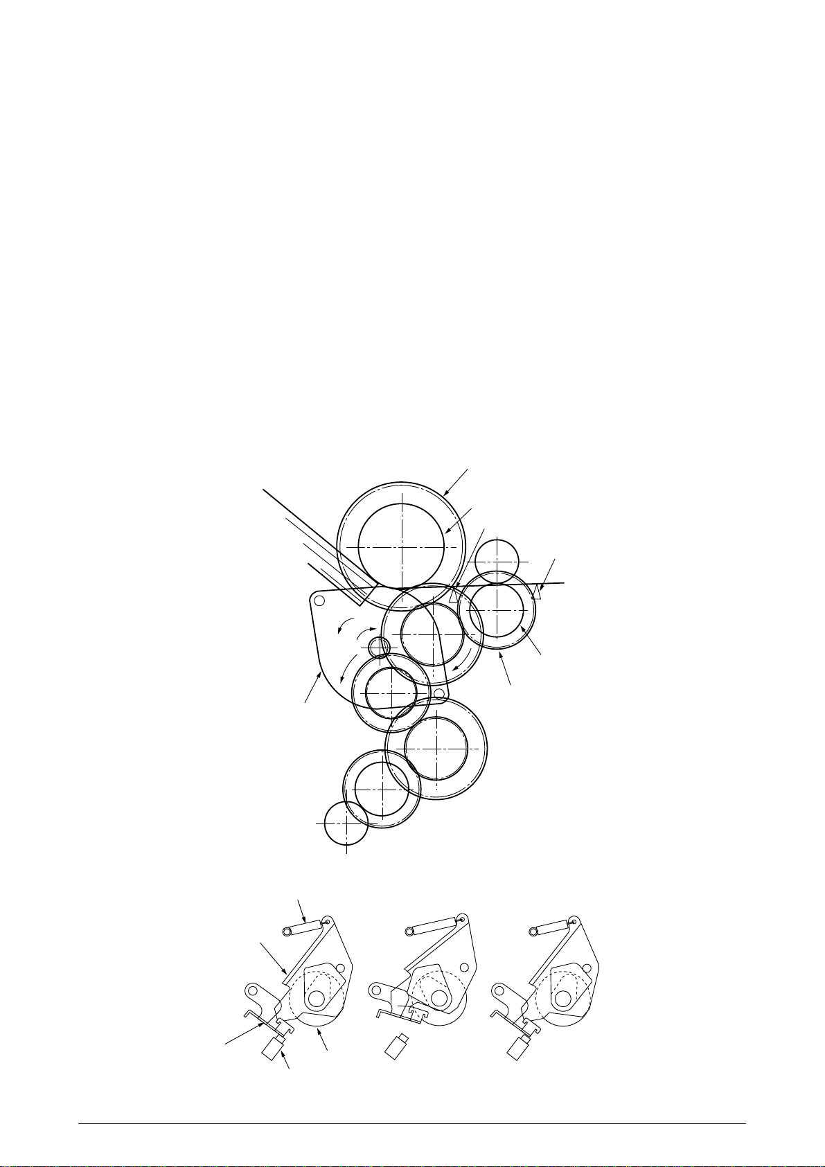
(2) Paper Feed from Multipurpose Tray (MT)
1. The release lever usually pushes down the hopping plate to a position that turns
microswitch on (Figure 2-7-a).
2. The running of the motor in the (a) direction drives the MT feed roller and turns the cam.
The cam pushes the release lever and the hopping plate picks up paper sent out by the
MT feed roller (Figure 2-7-b), where the registration roller Assy (B) does not move because
its one-way clutch gear (1) idles.
3. After the paper beginning turns the entrance sensor on, the paper is forwarded a fixed
length. The paper stops when its beginning reaches the registration roller Assy (B).
4. At the same time, the cam pushes down the hopping plate. The release lever that has been
placed in its original position by the spring locks the hopping plate (Figure 2-7-c).
5. After the completion of the paper feed operation, the registration motor runs in the arrow
direction (b) to drive the registration roller Assy (B), where the one-way clutch gear (2)
does not allow the MT feed roller to move.
One-way clutch gear (2)
MT feed roller
Entrance sensor
Paper
Entrance belt sensor
Registration motor
Release lever
Spring
b
a
Registration roller Assy (B)
One-way clutch gear (1)
Figure 2-7
Hopper plate
Feed roller
Microswitch
Figure 2-7-a Figure2-7-b Figure 2-7-c
41316401TH Rev.4 25 /
Page 26
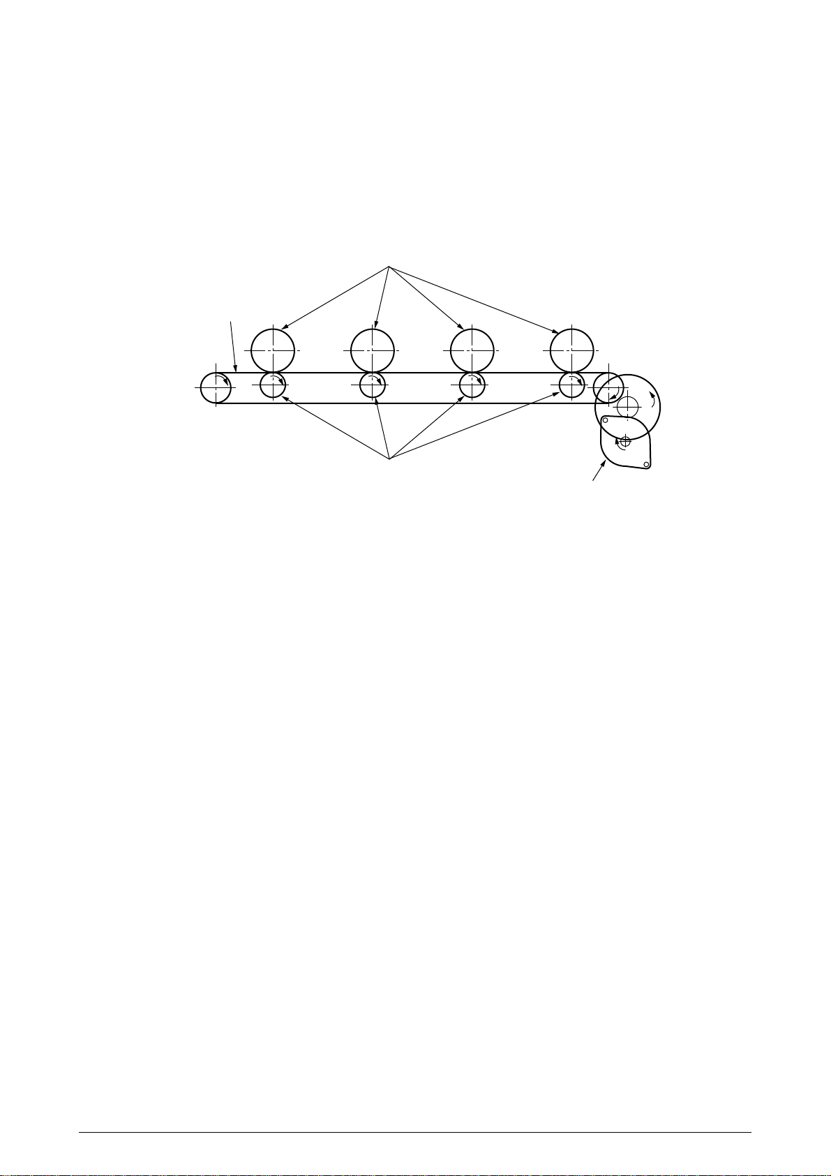
(3) Transport Belt
1. The running of the transport belt motor in the arrow direction (a) drives the transport belt.
The belt unit sits with one transport roller immediately below each color’s drum, and the
transport belt between them. By the application of a fixed voltage, the transport belt and
the transport roller feed paper on the transport belt into the fuser unit, transferring a toner
image on each color’s drum.
Drum
Transport belt
KYMC
Transport (transfer) roller
Transport (transfer) belt motor
Figure 2-8
41316401TH Rev.4 26 /
Page 27
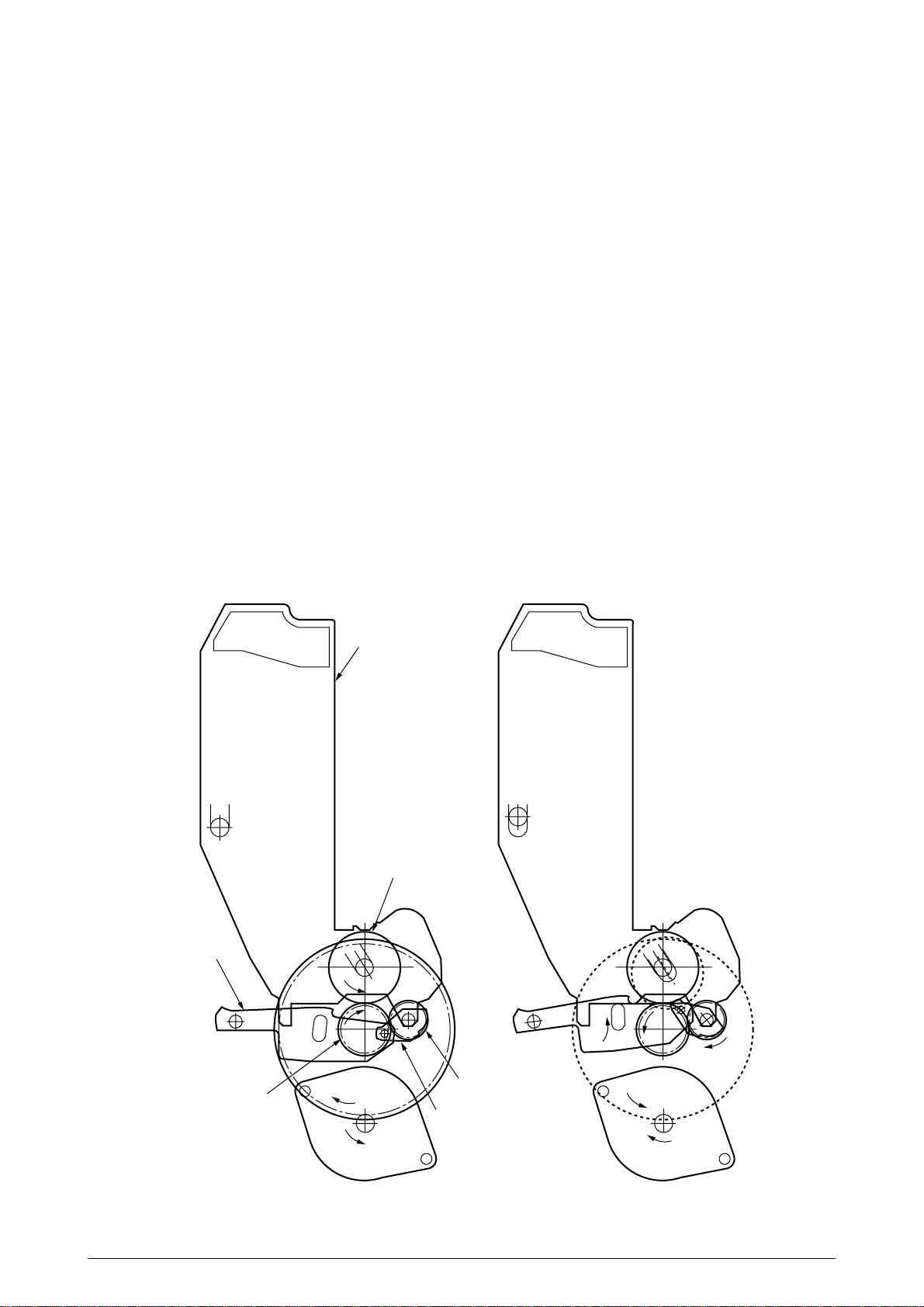
(4) Driving and Up-and-Down Movements of I/D Unit
1. The I/D unit driving and up-and-down movements are effected by a single-pulse motor.
The running of the main motor in the arrow direction (a) turns the lever 1 to the left. Then,
the lever 2 that was lifted by the lever 1 lowers to move down the I/D unit. After the up/
down sensor is turned off (Figure 2-9-d), specified downward pulsing places the I/D unit
in its lowest position, or equivalently, printing position (Figures 2-9-a and 2-9-c).
The drum gear engages with the driving gear and starts revolving to transfer an image on
the drum to running paper, where the one-way gear idles upon placement of the lever in
its lowest position.
2. With the running of the main motor in the arrow direction (b), the lever 1 pushes up the I/
D unit via the lever 2. After the up/down sensor is activated (Figure 2-9-d), the lever 1 lifts
the I/D unit to a specified level and stops to keep space to an extent between the drum and
the transport belt (Figures 2-9-c and 2-9-e).
The drum gear is not engaged with the driving gear and does not revolve.
3. When the two pins of the up/down sensor are pushed up by the I/D unit, and touches and
electrically connected to the plate above the pins, the sensor recognizes the on state.
When the two pins are pushed down by the I/D unit, and separated and insulated from the
plate, the sensor recognizes the off state.
The installation of the I/D unit can also be verified by recognizing the off state of the up/
down sensor.
Lever 2
Driving gear
I/D unit
a
Drum
One-way gear
Lever 1
b
Figure 2-9-a Figure 2-9-b
41316401TH Rev.4 27 /
Page 28
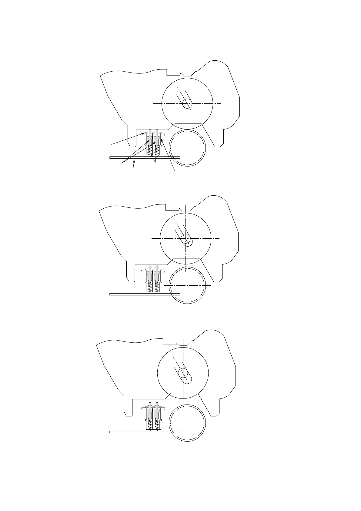
Plate
Pin Spring
Board
Up/down sensor
Figure 2-9-c
Figure 2-9-d
Figure 2-9-e
41316401TH Rev.4 28 /
Page 29
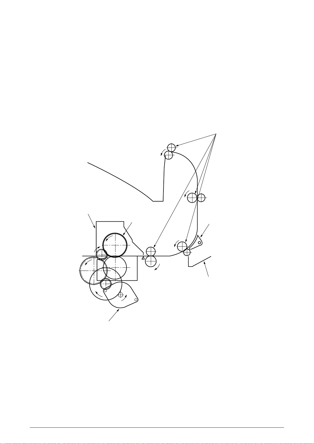
(5) Fuser Unit and Paper Ejection
1. A single-pulse motor drives the fuser unit and the eject rollers.
In response to the running of the heat motor in the arrow direction (a), the heat roller turns.
This roller fuses a toner image to paper by heat and pressure.
2. At the same time, the four eject rollers move to eject the paper.
3. The ejection path is switched back and forth between the route to the face-up stacker and
the route to the face-down stacker as follows. When the face-up stacker opens, the paper
separator inclines in the direction that guides the paper to the face-up stacker. When the
face-up stacker closes, the paper separator inclines in the direction that sends the paper
to the face-up stacker.
Eject rollers
Fuser unit
Heater motor
Heat rollers
a
Figure 2-10
Paper separator
Face-up stacker
41316401TH Rev.4 29 /
Page 30
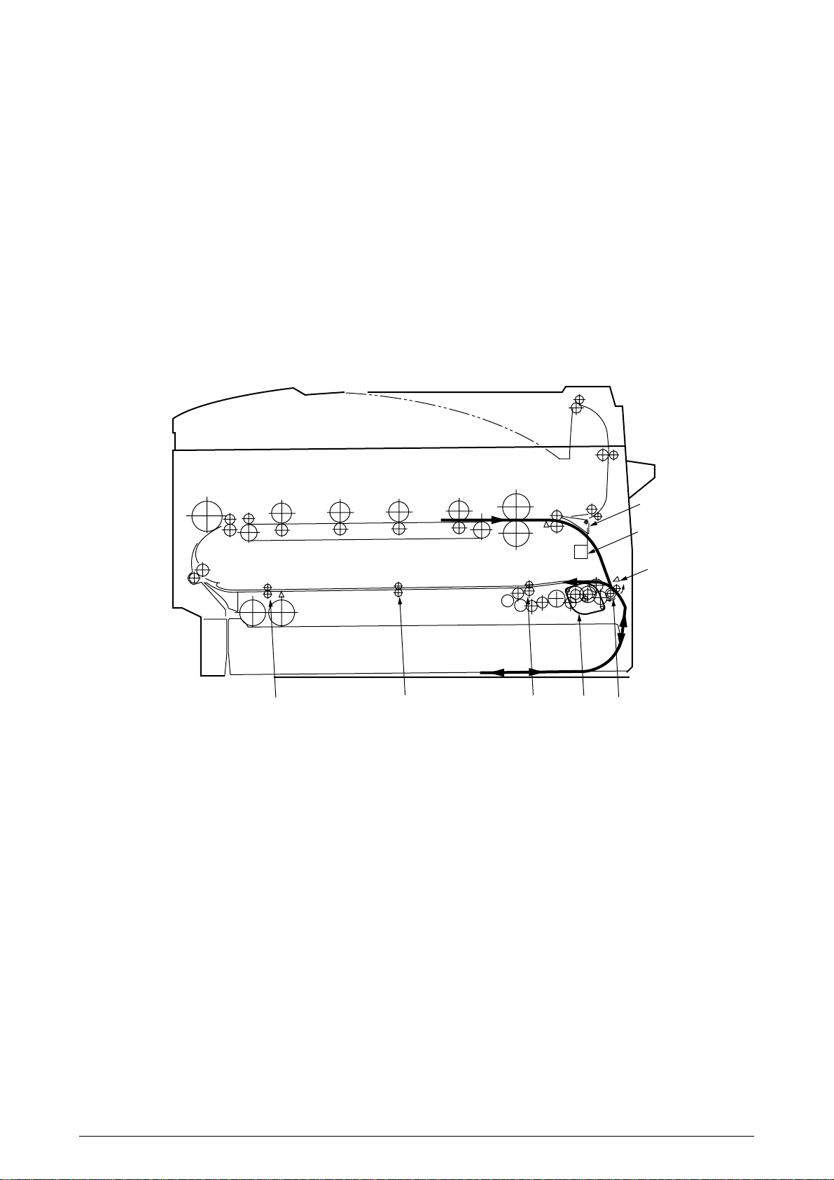
(6) Duplex Unit
1. When the duplex unit receives an instruction from the printer to print on both sides of a
sheet of paper, the solenoid opens the separator after the completion of one side printing
of a sheet of paper sent from the tray. The path is switched to that to the duplex unit.
At this time, as the roller (1) turns in the direction of the arrow “a,” the paper is retracted
on the rear of the cassette.
2. When fixed time has elapsed after the paper beginning passes through the duplex-in
sensor, the rollers reverse and the roller (1) turns in the direction of the arrow “b” to feed
the paper into the duplex unit. After that, the paper passes through the rollers (2), (3) and
(4), and ejected with the other side printed, and fed again into the printer.
Separator
Figure 2-11
Solenoid
Duplex-in sensor
b
a
Motor
Roller(2)Roller(3)Roller(4)
Roller(1)
41316401TH Rev.4 30 /
Page 31

2.5 Sensor
2.5.1 Paper related sensors
Paper eject roller
Heat roller
Stacker full sensor
C drum
K drumY drumM drum
Entrance belt sensor
MT feed roller
Exit sensor
Backup roller
Duplex in sensor
Duplex rear sensor
Duplex roller
Sensor
Entrance MT sensor
Entrance Cassette sensor
Entrance Belt sensor
Exit sensor
Duplex In sensor
Duplex Rear sensor
Duplex Front sensor
Stacker Full sensor
Driving roller
Driving roller
Belt cleaning blade
Registration roller B
Entrance MT sensor
1st feed roller
Duplex feed rollers
Transport belt
Duplex front sensor
Function
Detects the beginning of incoming paper to determine the
timing for switching from hopping to transport.
Detects the beginning of transported paper and, based on
the time taken until the paper beginning reaches the
sensor, determines the paper length.
Detects the beginning and end of paper to determine the
paper ejection timing.
Detects the beginning of paper that enters into the duplex
unit, to determine the time taken until the reversed rollers
turn in forward direction.
Detects the beginning of reversed paper in the duplex unit.
Detects the end of reversed paper in the duplex unit to
determine the paper ejection timing.
Detects the face-down stacker full of paper.
Pinch roller 2
2nd feed roller
Sensor status
ON
: Paper is present.
OFF
: Paper is absent.
ON
: Paper is present.
OFF
: Paper is absent.
ON
: Paper is present.
OFF
: Paper is absent.
ON
: Paper is present.
: Paper is absent.
OFF
: Paper is present.
ON
OFF
: Paper is absent.
ON
: Paper is present.
OFF
: Paper is absent.
ON
: Stacker is full.
OFF
: Stacker is empty.
Pinch roller 1
Registration roller A
Entrance cassette sensor
Auxiliary rollers
41316401TH Rev.4 31 /
Page 32

2.5.2 Other sensors
1 Paper Empty sensor
This sensor checks whether the paper cassette is empty.
2 Paper Near sensor
This sensor checks whether the paper cassette is near empty.
3 MT Paper Empty sensor
This sensor checks whether paper exists in the front feeder.
4 MT Hopping switch
This microswitch checks whether the front feeder table is in the up position or in the down
position.
5 Paper Size switch
This sensor detects the size of paper in the paper cassette.
6 ID Up/Down sensor (one for each of colors, Y, M, C and K)
This sensor checks whether the ID unit is in the up position or in the down position.
7 Toner K, Y, M and C sensors
These sensors checks whether the waste toner cartridges are full by measuring the time
interval between regular opening movements of toner sensors’ respective levers.
8 Temperature sensor
See section 2.7 (Transfer Control Responds to Environmental Changes).
9 Humidity sensor
See section 2.7 (Transfer Control Responds to Environmental Changes).
0 OHP sensor
This sensor detects the presence or the absence of transparencies.
A Alignment sensor
Upon correction of color misalignment, this sensor reads the alignment pattern printed at the
right and left ends of the transfer belt (see section 2.13).
41316401TH Rev.4 32 /
Page 33

2.6 Color Misalignment Correction
Each of the C7000 Series of printers is equipped with 4 ID units and LED heads, which can cause
color misalignment. This color misalignment is automatically corrected as follows:
(1) Color alignment to be corrected
1 Color misalignment in X-axis direction (Positional error caused by LED head)
2 Color misalignment in slanting direction (Positional error caused by LED head)
3 Color misalignment in Y-axis direction (Positional error caused by I/D unit and LED head)
(2) Correcting
A preset pattern to detect color misalignment is printed on the belt. The reflection sensor
reads the printed pattern, each color’s misalignment value is sensed and its correction value
is determined. The correction value is used each color’s (Cyan, Magenta and Yellow) writing
timing in comparison with that of Black.
2.7 Transfer Control Responds to Environmental Changes (Room Temperatures and
Relative Humidities)
The C7000 Series of printers measure the room temperature and the relative humidity using their
room temperature sensors and humidity sensors. An optimum transfer voltage under each
measurement environment is calculated to perform real-time control on printing with its optimum
voltage.
Value Read by
Sensor
5 10
10 15
15 20
20 25
25 30
30 35
Temperature (˚C)Temperature (˚C)
35 40
40
Value Read by
Sensor
5 10
10 15
15 20
20 25
25 30
30 35
35 40
40
Value Read by Sensor
Value Read by
Sensor Register Value
5
16B(H) 19E(H)
19E(H) 1D1(H)
1D1(H) 204(H)
204(H) 236(H)
236(H) 265(H)
265(H) 290(H)
290(H) 2B9(H)
2B9(H)
Value Read by Sensor
Value Read by
Sensor Register Value
5
16B(H) 19E(H)
19E(H) 1D1(H)
1D1(H) 204(H)
204(H) 236(H)
236(H) 265(H)
265(H) 290(H)
290(H) 2B9(H)
2B9(H)
59(H)
59(H)
Environment sensing table
7
7
7
6
5
4
4
2
2
Humidity (%)
45 55
5C(H) 70(H)
Humidity (%)
45 55
5C(H) 70(H)
H/H
15
15 25
1E(H)
1E(H) 33(H)
8
8
8
8
7
7
7
6
6
15
1E(H)
N/L1 N/L1 N/L2 N/N
N/L1
H/L
8
8
8
7
7
6
6
6
5
15 25
1E(H) 33(H)
L/L
H/L
25 35
33(H) 47(H)
25 35
33(H) 47(H)
47(H) 5C(H)
8
8
7
7
6
6
5
4
4
47(H) 5C(H)
N/L2 N/N
35 45
35 45
7
7
6
5
4
4
2
1
1
55 65
70(H) 85(H)
7
6
5
4
4
3
H/H H/H
1
1
1
55 65
70(H) 85(H)
H/H H/H
65 75
85(H) 99(H)
65 75
85(H) 99(H)
99(H) AE(H)
7
6
5
4
3
H/H H/H
1
1
1
1
99(H) AE(H)
H/H H/H
75 85
6
5
4
3
3
1
1
1
1
75 85
85
AE(H)
6
5
4
3
2
1
1
1
1
85
AE(H)
41316401TH Rev.4 33 /
Page 34

2.8 Paper Jam Detection
The C7000 Series of printers detect paper jams after power-on and during printing. When a paper
jam occurs, the printing operation is immediately suspended. After the cover is opened and the
jammed paper is removed, closing the cover resumes the printing.
Classification/Belt
STSOP/ 7
SSTOP/ 5
OPJAM/ 6
OPFEED/ 4
SSTOP/ 5
OPJAM/ 6
OPFEED/ 3
SSTOP/ 5
OPJAM/ 6
OPFEED/ 2, 1, 0
STSOP/ 5
OPJAM/ 5
STSOP/ 5
OPJAM/ 4
STSOP/ 5
OPJAM/ 3
STSOP/ 5
OPJAM/ 2
STSOP/ 5
OPJAM/ 1
STSOP/ 5
OPJAM/ 0
STSOP/ 4
OPAP/ 3
STSOP/ 4
OPAP/ 2, 1, 0
ERROR
Paper Size Error
The entrance cassette sensor has not turned off within fixed time after its
turn-on. Loading of multiple sheets of paper has been detected.
Misfeed from Duplex
Paper could not be loaded from the duplex transport assembly.
Transport Assembly
Misfeed from
Paper could not be loaded from the MT.
Multipurpose Tray (MT)
Misfeed from Cassette
Paper could not be loaded from the cassette 1, 2 or 3.
1, 2 or 3
Duplex Paper
Reversing Jam
Duplex Unit Entrance
Paper Jam
Duplex Unit Paper
The duplex rear sensor has not turned on during the paper reversing
operation of the duplex unit.
The duplex-in sensor has not turned on during the paper loading in
the duplex unit.
The duplex front sensor has not turned on during the operation.
Input Jam
Paper Ejection Jam
The paper exit sensor has not detected the end of paper within fixed
time after the detection of the beginning of it. The paper exit sensor
has not turned off since its turn-on.
Paper Transport Jam
The paper exit sensor has not turned on while paper is running on
the belt.
Loading Jam
Paper has not reached the entrance belt sensor or the MT sensor
after the completion of the hopping.
MT Paper Empty
Cassette 1, 2 or 3
There is no paper in the multipurpose tray.
There is no paper in the cassette 1, 2, or 3.
Paper Empty
Error Condition
Paper Ejection
Duplex-in
sensor
Duplex rear sensor
Paper exit sensor
Duplex Entry
Duplex rear sensor
Entrance belt sensor
Paper Transport
Duplex Input
Duplex front sensor
Cassette 1
Cassette 2
Cassette 3
Entrance FF sensor
Paper Ejection
Entrance cassette sensor
Multipurpose tray
(MT)
Misfeed from MT
Misfeed from Duplex Unit
Misfeed from Cassette 1
Misfeed from Cassette 2
Misfeed from Cassette 3
41316401TH Rev.4 34 /
Page 35

2.9 Cover-Open
When the top cover of the printer is open, the cover-open microswitch turns off to cut the high
voltage power and output of not less than 32V. At the same time, the CPU receives CVOPN signals
for indicating the status of the microswitch to handle the cover-open.
When the front cover is open, the microswitch also turns off and the 32V power to the duplex unit
is cut. The CPU receives FCOVER signals for indicating the status of the microswitch to handle
cover-open.
71K-PCB
Top cover
microswitch
Detection
Circuit
Detection
Circuit
CPU
66577
P10, 5
P7, 6
+32V
+32V
COVOPN (2P)
High voltage power supply board
HVOLT (16P)
Detection
Circuit
High voltage power supply unit
FCOVER(3P)
Front cover
microswitch
Duplex unit
Duplex (16P)
41316401TH Rev.4 35 /
+32V
V71-PCB
Page 36

2.10 Toner Low Detection
• Structure
The toner low detection device consists of the stirring gear that revolves at a constant speed,
the stirring bar, and the magnet on the stirring bar. The stirring bar turns in synchronization with
the protrusion of the stirring gear.
Stirring gear
Protrusion
Stirring bar
• Detection
A toner low condition is detected by measuring the contact time between the sensor lever magnet
and the stirring bar.
Toner low sensor
Sensor lever A
Toner Full Condition
• The stirring bar turns in synchronization with the
stirring gear.
Sensor lever B
• Even when the stirring bar magnet is place in its
highest position, the stirring bar turns by the force
of the stirring gear because the opposite side of
the bar is placed in toner.
Toner cartridge
Stirring bar
Toner low sensor
Toner Low Condition
Sensor lever A
• The stirring bar reaches its highest position, then
falls to its lowest position under its own weight
because of the absence of toner resistance on the
opposite side. In this situation, the bar-magnet
Sensor lever B
contact time becomes long. By measuring the
time, a toner low condition is detected.
Toner cartridge
Stirring bar
41316401TH Rev.4 36 /
Page 37

Toner Full Condition (12PPM)
t1
TNRSNS
T=2.3
Toner Low Condition (12PPM)
t1
TNRSNS
T=2.3
• When the toner low condition is detected 20 consecutive times, toner low is determined.
(The toner low message is displayed when about 500 A4 sheets at 5% density have been
printed after toner low had been detected.)
• When the toner full condition is detected 10 consecutive times, toner low is removed.
• When the toner sensor remains unchanged for more than 15 cycles of 2.3 seconds, the toner
sensor alarm is activated.
t1<1.08
t1>1.08
• The toner sensor does not perform the detection while the drum motor is not running.
2.11 Page Size Detection
Via the cam moves jointly with the paper guide of the paper cassette, the four tab pieces are driven
according to the set position of the paper guide.
Upon installation of the paper cassette, the microswitch detects the condition of the tab pieces and
the paper size is recognized.
State of Microswitch Paper Size
SW1 SW2 SW3 SW4
0 1 1 1 Letter
0 1 0 1 Executive
0011A4
1 1 1 0 Legal 14
1 0 1 1 Legal 13
1101B5
1100A5
1001A6
41316401TH Rev.4 37 /
Page 38

2.12 Operation at Power-on
2.12.1 Self-diagnostic test
(1) Initial test
The followings are automatically performed at power-on.
(a) ROM check
(b) RAM check
(c) EEPROM check
(d) Flash ROM check
(2) ROM check
ROM is checked by calculating a HASH value.
(3) RAM check
(a) RAMs are by type. Out-of-specification RAM is judged as an error.
(b) The order of mounted RAMs is checked. Out-of-standard order is judged as an error.
(c) Each slot’s RAM is checked by read-after-write operation.
(4) EEPROM check
Specific data stored at a fixed address of EEPROM is checked..
(5) Flash ROM check
The flash ROM format is checked. Unformatted ROM is formatted after read-after-write
checking.
(6) Option unit check
Before the printer goes into the operation mode, the presence of the option units (e.g., the
HDD, NIC, option trays and duplex unit) is checked.
41316401TH Rev.4 38 /
Page 39

2.13 Color Misalignment Detection
Reflection-type optical sensors for detecting color misalignment (Z71-PCB) are mounted on the
belt at the right and left ends, respectively, in front of the toner scraping (cleaning) blade which is
at the back of the belt unit. The color misalignment detection pattern is printed on the belt at each
of the right and left ends and, by reading the patterns by the reflection-type optical sensors, the
misalignment amounts are measured with respect to Black to determine correction values. Then,
the misalignment in main-scanning, sub-scanning and slanting directions is corrected.
These operations are performed at power-on, at cover-close and every 200 pages.
CMYK
ID
CMYK
Transfer
belt
LED head
Belt running direction
Color alignment sensors L and R
Transfer belt
Color alignment sensor R
Belt running direction
Color alignment sensor L
(Bottom View)
Cleaning blade
Cleaning blade
41316401TH Rev.4 39 /
Page 40

2.14 Version Read of Units Replaced Periodically
The version of each of the I/D, fuser unit and belt unit which are replaced periodically is determined
whether it is new or previous according to whether the fuse in it is conducting or out of conduction.
When the fuse is conducting, the unit is decided that it is new. The “new” or “previous” judgment
is performed at power-on and at cover-close. The life counter of every new unit is reset and the
“new” or “previous” judging purpose fuse in the unit is cut.
2.15 Life Count for Units Replaced Periodically
The life of each of the I/D, fuse unit and belt unit which are replaced periodically is counted as shown
in the following table:
Unit Name
I/D (Image Drum
Cartridge)
Toner Cartridge
Belt Unit
Fuser Unit
The number of drum revolutions is counted, on a letter paper length
+ continuous-printing paper interval basis.
End of Life: Time when a distance equivalent to pages of 20K is
printed (3P/J).
The number of dots printed is counted. The used amount is
determined based on the counter value (See section 2.16).
End of Life: Time when toner low occurs.
The number of drum revolutions is counted, on a letter paper length
+ continuous-printing paper interval basis.
The count of one is performed every time when one page is passed.
End of Life: Time when the counter value reaches 60K.
The count of one is performed every time when one page is passed.
End of Life: Time when the counter value reaches 60K.
2.16 Toner Consumption Detection
The used toner amount is detected by counting the number of dots printed.
The counting starts after toner low is removed. The sum of the counted values is stored in
EEPROM. Upon detection of toner low, the amount used is forcedly set to 8%. After that, when
the equivalent of pages of 1K on A4 and 5% duty is reached, toner-empty occurs and the printing
stops.
Condition
Action
Warning (the unit can still be used).
Do not use the unit anymore.
Warning (the unit can still be used).
Warning (the unit can still be used).
41316401TH Rev.4 40 /
Page 41

3. PARTS REPLACEMENT
This section describes the procedure for replacing the parts, assemblies and units in the field. The
replacing procedure is given for detachment. To attach, use the reverse procedure.
3.1 Precautions in Replacing Parts
(1) Before replacing the parts, be sure to remove the AC cable and the interface cable.
(a) To remove the AC cable, always use the following procedure.
i) Flip the power switch of the printer off (to “O”).
ii) Pull the AC inlet plug of the AC cable out of the AC receptable.
iii) Remove the AC cable and the interface cable from the printer.
(b) To connect the printer again, always use the following procedure.
i) Connect the AC cable and the interface cable to the printer.
ii) Insert the AC inlet plug into the AC receptacle.
iii) Flip the power switch of the printer on (to “I”).
Disconnect
(2) Do not disassemble the printer so long as it operates properly.
(3) Minimize the disassembly. Do not detach parts other than those shown in the replacing procedure.
(4) For maintenance, use designated tools.
(5) Follow the order instructed to disassemble the printer. Incorrect order may damage the parts.
(6) Small parts such as screws and collars tend to get lost, so temporarily place and fix them in
(7) When handling ICs and circuit boards such as microprocessors, ROMs and RAMs, do not use
Connect
their original positions.
gloves that likely to have static.
(8) Do not place the printed circuit boards directly on the printer or the floor.
41316401TH Rev.4 41 /
Page 42

[Maintenance Tools]
Table 3-1 lists tools necessary to replace the FRU's (Field Replaceable Units).
Table 3-1 Maintenance Tools
No.
1
2
3
4
5
6
7 1
8
No. 1-100 Philips
screwdriver
No. 2-200 Philips
magnetic screwdriver
No. 3-100 screwdriver
No. 5-200 screwdriver
Digital multimeter
Pliers
Handy cleaner
LED Head cleaner
P/N 4PB4083-2248P001
Q' ty Use for RemarkMaintenance Tools
1
Screws of 2 to 2.5mm
1
Screws of 3 to 5mm
1
1
1
1
1
LED head cleaning
41316401TH Rev.4 42 /
Page 43

3.2 Parts layout
B
B
A
B
B
A
A
Figure 3-1
41316401TH Rev.4 43 /
Page 44

[Top Cover Assy]
Figure 3-2
41316401TH Rev.4 44 /
Page 45

[Printer Unit-1/2]
Figure 3-3
A
A
41316401TH Rev.4 45 /
Page 46

[Printer Unit-2/2]
45
Figure 3-4
41316401TH Rev.4 46 /
Page 47

[Cassette Guide Assy (L),(R)]
B
A
C
C’
A
B
C
C’
Figure 3-5
41316401TH Rev.4 47 /
Page 48

[Duplex Unit]
D
C
G
B
A
E
F
D
C
G
B
F
A
E
Figure 3-6
41316401TH Rev.4 48 /
Page 49

3.3 Replacing Parts
This section describes how to replace the parts and assemblies shown in the following disassembling
system diagram.
C7000 41256201
Print Engine Controller PWB (3.3.23)
X 4
LED Assy (3.3.2)
40737401
Low Voltage Power Supply (3.3.36)
40737601
High Voltage Power Supply (3.3.37)
Cassette Guide
Printer Unit
4112801PP
Insurator
PB4076-5290P001
Main Cooling Fan Assy (3.3.19)
2381018P0001
HV T ape Harness
40847301
Main Motor Assy (3.3.33)
40846001
Main Feeder Motor (3.3.34)
40848801
Transport (Transfer) Belt Motor Assy (3.3.35)
40850201
Contact Assy (3.3.35)
41303601
Left Plate Assy (3.3.35)
40866301PA
Multipurpose Tray Cover Assy (3.3.14)
40864301
Rear Cover (3.3.10)
40864401
Left Side Cover (3.3.12)
40864501
Right Side Cover (3.3.13)
40864601
Front Cover Assy (3.3.7)
41042501
Front Cover Inner Baffle (3.3.7)
1PA4128-1074G001
Face Up Tray (3.3.11)
40864901PA
Frame Assy - Release
A
40839001
Left Cassette Guide Assy (3.3.39)
40839401
Right Cassette Guide Assy (3.3.40)
40839801
Main Feed Assy (3.3.38)
4PP4122-1217P001
40371301
Feed Roller (3.3.9)
40325401
Main Feeder Drive Gear (3.3.38)
40313201
Nudger Roller (3.3.9)
40841101
Printer Chassis (3.3.16)
40844301
Regist Roller Assy (A) (3.3.16)
40844303
Regist Roller Assy (B) (3.3.17)
40845801
Registration Motor Assy (3.3.18)
41187101
Registration Clutch (3.3.18)
40859201
Duplex Guide Assy (3.3.21)
40848501
Main Feeder Drive Gear A (3.3.34)
40846601
Main Feeder Drive Gear B (3.3.34)
40841401
Fuser Latching Handle (R) (3.3.32)
40841501
Fuser Latching Handle Spring (3.3.32)
Plastic Slide (3.3.40)
40349101
Cassette Guide Pivot (L) (3.3.40)
40349701
Plastic Roller (3.3.40)
40928101
Cassette Spring (3.3.40)
4PP4076-5359P001
Cassette Lock (3.3.40)
4PP4043-4526P001
Cassette Lock Spring (3.3.40)
4PB4016-1960P002
Foot (3.3.40)
40368304
Paper Size Sensing PWB PXC (3.3.40)
4PP4076-5360P001
Paper Size Actuator (3.3.40)
41143701
Duplex Assy Ground contact (3.3.40)
41309301
2nd Tray Connector (3.3.40)
41285701PA
Plate Assy-SW(Front) (3.3.40)
4PP4122-1217P001
Plastic Slide (3.3.39)
40349102
Cassette Guide Pivot (R) (3.3.39)
40349701
Plastic Roller (3.3.39)
40928101
Cassette Spring (3.3.39)
4PP4076-5359P001
Cassette Lock (3.3.39)
4PP4043-4526P001
Cassette Lock Spring (3.3.39)
4PB4016-1960P002
×
2
40841301
Fuser Latching Handle (L) (3.3.30)
40841501
Fuser Latching Handle Spring (3.3.30)
40841601
Entrance Sensor Actuator #1 (3.3.25)
40841701
Entrance Sensor Actuator #2 (3.3.27)
40841801
Entrance Senspr Actuator #3 (3.3.27)
40842201
Waste Toner Sensor Actuator (3.3.27)
41253601
Duplex Gate solenoid Assy (3.3.28)
41253701
Registration Shutter Solenoid Assy
41275201
Registration Shutter
41275301
Registration Shutter Spring
41067201
Fuser Drive Gear-C (3.3.28)
40323901
Fuser Exit Roller (3.3.28)
40316301
Fuser Drive Gear-B (3.3.28)
4PP4076-3949P001
Fuser Exit Roller Bushing (L) (3.3.28)
4PP4043-4489P001
Fuser Exit Roller Bushing (R) (3.3.28)
41189701
Drum Contact Assy (3.3.15)
41258301
Entrance Sensor PWB (3.3.26)
41312801
Left Top Cover Spring Assy (3.3.24)
41312901
Right Top Cover Spring Assy (3.3.24)
40346801
Color Registration Sensor Assy (3.3.20)
41073601
Exit Sensor Assy (3.3.29)
Foot (3.3.39)
41275801PA
Microswitch-Assy (3.3.40)
41275901PA
Microswitch-Assy (3.3.40)
×
4
×
2
41316401TH Rev.4 49 /
Page 50

A
CU Board Assy
Top Cover
40862002
Multipurpose Feeder Assy (3.3.14)
40952702
Multipurpose Feeder
Top Cover (3.3.14)
40866701
Cassette Assy (3.3.8)
41395304
Board Assy-CU
41356004
Board_CRM
41286901
Plate_Shield
41278601
×
Guide_Rail (A)
41278701
Guide_Rail (B)
41371601
Plate_Support (C)
41395401
Plate_Support (FAN)
41410201
Motor-Fan 60x60x15
41278401
Screw
PB4013-3100P006 x10
Cup Screw (S Tight M3)
P3-6G
Screw (Round Head)
PB4083-2500P008
Tapping Screw
PSW2W3-18C
Screw(Round Head, SW+2W)
41467401
Plate FG (Centronics)
41597401
Label_Caution DIMM
41607101
Gasket
40859701
Top Cover (3.3.1)
4126001
Control Panel Bezel (3.3.4)
40325101
Multipurpose Feeder Drive Gear (3.3.14)
41045802
×
Link (3.3.14)
4YB4120-1137P001
MT Paper Empty Sensor (3.3.14)
40863201
MT OHP Sensor (3.3.14)
41276001
MT Position Sensor (3.3.14)
40927901
Retard Pad Assy (3.3.8)
4PP4043-4698P001
Retard Pad Assy Spring (3.3.8)
2
2
×
2
×
2
×
2
×
2
40946809
PCB Assy_CRM
41469503
Board_TNY
41356110
Japanese font ROM DIMM Board_TNO
(Two Heisei fonts)
41437402
Board Memory 64MB
×
2
×
2
41316501
Top Cover Inner Frame Assy (3.3.4)
40861001
×
LED Assy Spring (3.3.2)
41257901
LED Control PWB (Y71) (3.3.4)
40365404
Stack Full Sensor (3.3.4)
40860601 Z 4
Eject Roller (3.3.4)
41297301
Control Panel Assy (3.3.4)
2381005P0015
Control Panel Tape Harness (3.3.4)
41309601
LED Harness K (3.3.4)
41309602
LED Harness Y (3.3.4)
41309603
LED Harness M (3.3.4)
41309604
LED Harness C (3.3.4)
40861201
Top Cover Handle (3.3.5)
40861301
Top Cover Latch (3.3.5)
40861401
Top Cover Latch Spring (3.3.5)
40861501
Eject Guide Assy (3.3.6)
8
×
2
41316401TH Rev.4 50 /
Page 51

3.3.1 Top Cover
(1) Open the Top Cover assy.
(2) Remove the nine screws 1 to detach the top cover 2.
2
1
Figure 3-3-1 Top Cover
1
1
41316401TH Rev.4 51 /
Page 52

3.3.2 LED Assy/ LED Assy Spring
(1) Open the top cover 1.
(2) Remove the three cables, and unhook the LED Assy 2 at two places to demount it (the two
springs 3 become detached together with the LED Assy 2).
(3) Remove the LED connector 4.
When assembling, attach the LED connector 4 to the LED head and insert the flat cable into it.
1
3
4
3
2
4
Figure 3-3-2 LED Assy/ LED Assy Spring
41316401TH Rev.4 52 /
Page 53

3.3.3 Top Cover Unit
(1) Remove the top cover (see section 3.3.1).
(2) Remove the rear cover (see section 3.3.10).
(3) Remove the left side cover (see section 3.3.12).
(4) Remove the right side cover (see section 3.3.13).
(5) Remove the shield plates A and B (see section 3.3.22), and unplug the connector to separate
the top cover.
(6) Disengage the top cover unit 1 at two places to detach it.
1
Figure 3-3-3 Top Cover Unit
41316401TH Rev.4 53 /
Page 54

3.3.4 Control Panel Assy/ Control Panel Bezel/ LED Control PWB/ Toner Sensors/ Stacker Full Sensor/
Control Panel/ Control Panel Tape Harness/ Eject Rollers
(1) Detach the control panel bezel placed in the control panel Assy 2.
(2) Remove the screw 1 to demount the control panel Assy 2.
(3) Detach the control panel tape harness D.
(4) Remove the top cover unit (see section 3.3.3).
(5) Unscrew the four screws 3 to remove the earth plate 4.
(6) Remove the two screws 5, unhook all the connectors 6 and demount the LED control PWB 7.
(7) Remove the screw 8.
(8) Disengage the four claws to demount the toner sensor B.
(9) Demount the stacker full sensor C.
(10)Demount the exit rollers E.
(11)Detach the LED harnesses, K, Y, M and C F.
(12)Detach the top cover inner frame Assy G.
3
5
C
E
G
E
F
5
1
7
6
B
D
2
Figure 3-3-4 Control Panel Assy/ Control Panel Bezel/ LED Control PWB/ Toner Sensors/ Stacker
Full Sensor/ Control Panel/ Control Panel Tape Harness/ Eject Rollers
41316401TH Rev.4 54 /
Page 55

3.3.5 Top Cover Handle/ Top Cover Latch/ Top Cover Latch Spring
(1) Remove the two screws 1 to detach the top cover handle 2 and disengage the top cover latch
3 (at the same time, the two top cover latch springs 4 become detached).
1
3
2
1
4
4
Figure 3-3-5 Top Cover Handle/ Tope Cover Latch/ Top Cover Latch Spring
41316401TH Rev.4 55 /
Page 56

3.3.6 Eject Guide Assy
(1) Remove the five screws 1 to detach the eject guide Assy 2.
1
1
1
2
Figure 3-3-6 Eject Guide Assy
41316401TH Rev.4 56 /
Page 57

3.3.7 Cassette Assy/ Front Cover Assy/ Front Cover Inner Baffle
(1) Detach the cassette Assy 1.
(2) Open the front cover 2, and disengage it at two places to detach it.
(3) Detach the front cover inner baffle 3.
3
1
Figure 3-3-7 Cassette Assy/ Front Cover Assy/ Front Cover Inner Baffle
2
41316401TH Rev.4 57 /
Page 58

3.3.8 Retard Pad Assy/ Retard Pad Assy Spring
(1) Remove the cassette 1.
(2) Detach the retard pad Assy 2 (at the same time, the spring 3 becomes detached).
2
1
Figure 3-3-8 Retard Pad Assy/ Retard Pad Assy Spring
3
41316401TH Rev.4 58 /
Page 59

3.3.9 Feed Roller and Nudger Roller
(1) Remove the cassette.
(2) Unlatch and demount the feed roller 1.
(3) Unlatch and demount the nudger roller 2.
2
1
Figure 3-3-9 Feed Roller and Nudger Roller
41316401TH Rev.4 59 /
Page 60

3.3.10 Rear Cover
(1) Remove the left side cover (see section 3.3.12).
(2) Remove the four screws 2 to detach the rear cover 1.
Note!
When attaching the rear cover, take care not to allow the spring 3 to get caught in parts.
3
2
1
2
2
Figure 3-3-10 Rear Cover
41316401TH Rev.4 60 /
Page 61

3.3.11 Face-Up Tray
(1) Open the face-up tray 1 in the arrow direction, and disengage it at two places to detach it.
Figure 3-3-11 Face-Up Tray
1
41316401TH Rev.4 61 /
Page 62

3.3.12 Left Side Cover
(1) Open the top cover 1.
(2) Open the front cover 2 and undo the screw 3.
(3) Remove the four screws 4 to detach the left side cover 5.
4
4
1
4
5
Figure 3-3-12 Left Side Cover
3
2
41316401TH Rev.4 62 /
Page 63

3.3.13 Right Side Cover
(1) Open the top cover 1.
(2) Open the front cover 2 and undo the screw 3.
(2) Remove the four screws 4 to detach the right side cover 5.
4
4
1
5
3
2
Figure 3-3-13 Right Side Cover
41316401TH Rev.4 63 /
Page 64

3.3.14 Multipurpose Tray Assy/ Multipurpose Tray Cover Assy/ Links/ Multipurpose Tray Top Cover/
Multipurpose Tray Drive Gear
(1) Remove the left side cover (see section 3.3.12).
(2) Remove the right side cover (see section 3.3.13).
(3) Remove the left plate Assy (see section 3.3.22).
(4) Remove the three screws 1 to detach the multipurpose tray top cover 2.
(5) Remove the three screws 3 (two of them are black) and the connector to detach the multipurpose
tray 4.
(6) Disengage A and B at both sides of the assembly to detach the multipurpose tray cover Assy
5 (at the same time, the links 7 become detached).
(7) Unhook and detach the multipurpose tray drive gear 8.
7
3
1
1
8
2
4
7
3
3
B
B
A
8
A
5
Figure 3-3-14 Multipurpose Tray Assy/ Multipurpose Tray Cover Assy/ Links/ Multipurpose Tray Top
Cover/ Multipurpose Tray Drive Gear
41316401TH Rev.4 64 /
Page 65

3.3.15 Drum Contact Assys
(1) Insert a flatblade screwdriver between the printer case and the drum contact Assy 1 to demount
the drum contact Assy 1.
1
Figure 3-3-15 Drum Contact Assys
41316401TH Rev.4 65 /
Page 66

3.3.16 Registration Roller Assy (A)/ Registration Drive Gear (A)
(1) Remove the left side cover (see section 3.3.12).
(2) Remove the right side cover (see section 3.3.13).
(3) Remove the multipurpose tray (see section 3.3.14).
(4) Remove the four screws 1 to demount the registration roller Assy (A) 2.
(5) Remove the E ring 3 to detach the registration gear (A) 4.
1
4
3
1
2
Figure 3-3-16 Registration Roller Assy (A)/ Registration Driver Gear (A)
41316401TH Rev.4 66 /
Page 67

3.3.17 Registration Roller Assy (B)
(1) Remove the cassette Assy.
(2) Open the front cover.
(3) Remove the right side cover (see section 3.3.13).
(4) Remove the left plate Assy (see section 3.3.22).
(5) Remove the registration clutch (see section 3.3.18).
(7) Unscrew the four screws 1, and pull out the registration Assy (B) 1 in the arrow direction.
2
1
1
1
Figure 3-3-17 Registration Roller Assy (B)
41316401TH Rev.4 67 /
Page 68

3.3.18 Registration Clutch and Registration Motor Assy
(1) Remove the left side cover (see section 3.3.12).
(2) Remove the left plate Assy (see section 3.3.22).
(3) Remove the connector and the E ring 1, then remove the two screws 3, the earth 4 and the
registration clutch 2.
(4) Remove the connector to remove the two screws 5 and the registration motor Assy 6.
5
2
Figure 3-3-18 Registration Clutch and Registration Motor Assy
6
5
3
4
3
1
41316401TH Rev.4 68 /
Page 69

3.3.19 Main Cooling Fan
(1) Unhook the connector (1), and remove the screw (2) and the cooling fan (3).
Note!
When attaching the cooling fan, observe its correct orientation.
Figure 3-3-19 Main Cooling Fan
Outlet
3
1
2
41316401TH Rev.4 69 /
Page 70

3.3.20 Color Registration Sensor Assy
(1) Remove the two screws 1 and the two connectors to demount the color registration sensor
Assy 2.
(2) Remove the earth plate B 3.
1
1
2
3
Connectors
Figure 3-3-20 Color Registration Sensor Assy
41316401TH Rev.4 70 /
Page 71

3.3.21 Duplex Guide Assy
(1) Unlatch and demount the duplex guide 1.
1
Main chassis (rear)
Figure 3-3-21 Duplex Guide Assy
41316401TH Rev.4 71 /
Page 72

3.3.22 Electrical Chassis Cooling Fan
(1) Unscrew the screws 1 to remove the plate A 2.
(2) Unscrew the screws 3 to remove the shield plate B 4.
(3) Remove the printer engine controller PWB (see section 3.3.30).
(4) Unscrew the screws 5 to remove the shield plate 6.
(5) Unscrew the screws 7 to demount the electrical chassis cooling fan 8.
1
1
7
8
6
2
4
5
5
3
5
Outlet
5
3
Figure 3-3-22 Electrical Chassis Cooling Fan
41316401TH Rev.4 72 /
Page 73

3.3.23 Printer Engine Controller PWB
(1) Remove the right side cover (see section 3.3.13).
(2) Remove the left plate Assy (see section 3.3.22).
(3) Remove the five screws 1 and all the connectors to demount the printer engine controller
PWB 2.
2
Figure 3-3-23 Printer Engine Controller PWB
1
1
41316401TH Rev.4 73 /
Page 74

3.3.24 Printer Unit Chassis
(1) Unscrew the two screws 1 and remove the AC inlet 2.
(2) Unscrew the four black screws 3 and five screws 4 to detach the printer unit chassis 5.
(3) Unscrew the four black screws 6 and remove the left top cover spring Assy 7.
(4) Unscrew the four black screws 8 and remove the right top cover spring Assy 9.
6
6
3
7
4
4
3
4
9
5
8
8
3
4
3
2
1
Figure 3-3-24 Pinter Unit Chassis
41316401TH Rev.4 74 /
Page 75

3.3.25Entrance Cassette Sensor Actuator
(1)Remove the printer unit chassis (see section 3.3.24).
(2)Turn over the main chassis.
(3)Remove the two clamps with needlenose pliers to detach the entrance cassette sensor actuator 1.
1
Main chassis
Figure 3-3-25 Entrance Cassette Sensor Actuator
41316401TH Rev.4 75 /
Page 76

3.3.26Entrance Sensor PWB
(1)Remove the registration roller Assy (B) (see section 3.3.17).
(2)Remove the two screws 1 to detach the entrance sensor PWB 2.
1
2
Figure 3-3-26 Entrance Sensor PWB
41316401TH Rev.4 76 /
Page 77

3.3.27 Entrance MT Sensor Actuator and Entrance Belt Sensor Actuator
(1) Remove the entrance sensor PWB (R71) (see section 3.3.26).
(2) Unlatch and detach the entrance MT sensor actuator 1.
(3) Unlatch and detach the entrance belt actuator 2.
2
1
Figure 3-3-27 Entrance MT Sensor Actuator and Entrance Belt Sensor Actuator
41316401TH Rev.4 77 /
Page 78

3.3.28 Fuser Exit Roller
(1) Unscrew the two screws 1 to remove the duplex gate solenoid Assy 2.
(2) Unscrew the screw 3 to remove the fuser exit roller contact 4.
(3) Remove the fuser drive gear -A 5 and fuser drive gear -A 6.
(4) Unscrew the screw 7 to remove the fuser drive gear -C 8.
(5) Unlatch and detach the fuser drive gear -B 9 and fuser exit roller bush (R) 0.
(6) Unlatch and detach the fuser exit roller bush (L) A and fuser exit roller B.
B
A
1
7
8
0
9
6
5
3
4
2
Figure 3-3-28 Fuser Exit Roller
41316401TH Rev.4 78 /
Page 79

3.3.29Exit Sensor Assy
(1)Remove the fuser exit roller (see section 3.3.28).
(2)Remove the screw 1 and connector to detach the (red and blue) exit sensor Assy 2.
1
2
Figure 3-3-29 Exit Sensor Assy
41316401TH Rev.4 79 /
Page 80

3.3.30 Fuser Latching Handle (L)
(1) Remove the latching handle spring 1.
(2) Unscrew the screw 2 to detach the fuser latching handle (L) 3.
1
3
2
Figure 3-3-30 Fuser Latching Handle (L)
41316401TH Rev.4 80 /
Page 81

3.3.31Belt Motor Assy
(1)Remove the fuser latching handle (R) (see section 3.3.32).
(2)Remove the two screws 1 to detach the two connectors 2.
(3)Detach the blt motor Assy 3.
1
3
1
2
Figure 3-3-31 Belt Motor Assy
41316401TH Rev.4 81 /
Page 82

3.3.32 Fuser Latching Handle (R)
(1) Remove the printer unit chassis (see section 3.3.24).
(2) Remove the E ring 1.
(3) Remove the fuser latching handle spring 2 to detach the fuser latching handle (R) 3.
3
2
1
Figure 3-3-32 Fuser Latching Handle (R)
41316401TH Rev.4 82 /
Page 83

3.3.33Main Motor Assy
(1)Remove the belt motor Assy (see section 3.3.31).
(2)Remove all the connectors.
(3)Remove the four screws 1 to detach the main motor Assy 2.
1
2
1
1
Figure 3-3-33 Main Motor Assy
41316401TH Rev.4 83 /
Page 84

3.3.34 Main Feeder Drive Motor
(1) Remove the two screws 1 to detach the main feeder drive motor 2.
(2) Unscrew the screw 3 to remove the main feeder drive motor bracket 4.
(3) Remove the main feeder drive motor gears A 5 and B 6.
1
5
2
6
4
1
3
Figure 3-3-34 Main Feeder Drive Motor
41316401TH Rev.4 84 /
Page 85

3.3.35 Contact Assy/ Left Plate Assy
(1) Remove the printer unit chassis (see section 3.3.24).
(2) Remove the four screws 1 to detach the left plate Assy 2.
(3) Remove the screw 3 to detach the contact Assy 4.
4
1
1
2
3
Figure 3-3-35 Contact Assy/ Left Plate Assy
41316401TH Rev.4 85 /
Page 86

3.3.36Low Voltage Power Supply
(1)Remove the printer unit chassis (see section 3.3.24).
(2)Unhook the connector 1.
(3)Unscrew the screw 2 to remove the earth cable 3.
(4)Unscrew the six screws 4 to detach the low voltage power supply 5.
1
4
2
4
3
5
4
Figure 3-3-36 Low Voltage Power Supply
41316401TH Rev.4 86 /
Page 87

3.3.37 High voltage power supply
(1) Remove the contact Assy (see section 3.3.35).
(2) Unhook the connector of the high voltage power supply 2.
(3) Remove the two screws 1 to detach the high voltage power supply (2) and the tape harness 3.
1
3
2
1
Figure 3-3-37 High Voltage Power Supply
41316401TH Rev.4 87 /
Page 88

3.3.38Main Feed Assy
(1)Remove the printer unit chassis (see section 3.3.24).
(2)Remove the low voltage power supply and high voltage power supply (see sections 3.3.36 and
3.3.37).
(3)Unscrew the five screws 1 to remove the lower plate 2.
(4)Unscrew the four screws 3 to detach the main feed Assy 4.
(5)Unhook and remove the main feed drive gear 5.
1
1
2
1
3
1
3
5
4
Figure 3-3-38 Main Feed Assy
41316401TH Rev.4 88 /
Page 89

3.3.39 Cassette/ Left Guide Assy
(1) Remove the printer unit chassis (see section 3.3.24).
(2) Remove the main feed Assy (see section 3.3.38).
(3) Remove the three screws 1 to detach the left cassette guide Assy 2. At the same time, the
earth plate 3 becomes detached.
(4) Remove the cassette lift spring 4, then remove the plastic slide 5, the cassette lift arm (L) 6
and the plastic roller 7.
(5) Remove the two feet 8.
(6) Remove the cassette lock spring 9, then remove the cassette lock 0.
2
5
8
4
7
1
9
0
3
6
8
1
Figure 3-3-39 Cassette/ Left Guide Assy
41316401TH Rev.4 89 /
Page 90

3.3.40 Cassette/ Right Guide Assy
(1) Remove the printer unit chassis (see section 3.3.24).
(2) Remove the main feed Assy (see section 3.3.38).
(3) Remove the five screws 1 to detach the right cassette guide Assy 2. At the same time, the
earth plate 3 becomes detached.
(4) Remove the cassette lift spring 4, then detach the plastic slide 5, the cassette lift arm (L) 6
and the plastic roller 7.
(5) Unscrew the screw 8 to remove the paper size actuator 9.
(6) Unscrew the screw 0 to remove the paper size sensing PWB A in the downward direction.
(7) Remove the two feet B.
(8) Remove the cassette lock spring C, then remove the cassette lock D.
(9) Unscrew the two screws E to remove the 2nd tray connector F.
(10)Unscrew the screw G, then remove the duplex Assy ground contact H.
1
H
G
0
B
A
9
8
5
D
C
3
2
4
6
7
A
F
E
1
Figure 3-3-40 Printer Tray/ Right Guide Assy
41316401TH Rev.4 90 /
Page 91

3.3.41 Fuser Unit
(1) Open the top cover 1.
(2) Push the right and left fuser levers (blue) 2 in the arrow direction to detach the fuser unit 3.
3
1
2
2
Figure 3-3-41 Fuser Unit
41316401TH Rev.4 91 /
Page 92

3.3.42 Belt Unit
(1) Open the top cover 1.
(2) Remove the I/D unit.
(3) Push the lever (blue) 2 in the arrow direction, raise the handle (blue) and detach the belt unit
3.
Handle (blue)
3
1
2
Figure 3-3-42 Belt Unit
41316401TH Rev.4 92 /
Page 93

3.3.43 Duplex Unit
(1) Remove the cassette Assy, the front cover Assy and the front cover inner baffle.
(2) Unlatch the rear at the right and left, and pull the duplex unit 1 toward the front.
Latch
Figure 3-3-43 Duplex Unit
Latch
1
41316401TH Rev.4 93 /
Page 94

3.3.44 Guide Rails (L) and (R)
(1) Remove the duplex unit (see section 3.3.43).
(2) Remove the six screws 1 to detach the guide rails (L) 2 and (R) 3.
1
1
2
3
1
1
Figure 3-3-44 Guide Rail (L), (R)
41316401TH Rev.4 94 /
Page 95

3.3.45 Duplex Transport Assembly
(1) Turn over the duplex transport Assy.
(2) Unscrew the three screws 1 and five screws 2 to detach the plate 3.
(3) Unplug the connector and detach the mold Assy 4.
(4) Detach the two actuators 5.
(5) Unscrew the screws 6 and 7 to remove the earth 8.
(6) Unhook the connector and disengage the two claws to detach PCB-MOP 9.
(7) Unplug the cable and, warping the claw, detach the transport sensor.
(8) Unscrew the two screws to detach the cord duplex connector Assy.
(9) Unscrew the screw 0 to remove the earth A.
(10)Unscrew the screw B to remove the earth C.
(11)Unscrew the screw D to remove the earth E.
(12)Detach the bush F, gear G and bush H, then detach the roller I.
(13)Unscrew the screw J to remove the earth K.
(14)Detach the gear L and bush M. At the same time, the mini pitch belt N becomes detached.
(15)Detach the gear O and bush P, then detach the roller Q. At the same time, the mini pitch belt
R becomes detached.
(16)Unscrew the screw S to remove the earth T.
(17)Remove the E ring U and three screws V to detach the motor Assy W. At the same time, the
earth X becomes detached.
(18)Detach the gear Y and bush Z.
(19)Detach the gear [, knock-pin \ and bush ], then detach the roller _.
(20)Detach the bush a, gear b, knock-pin c and bush d, then detach the roller e. At the same
time, the earths f and g become detached.
(21)Detach the idle roller shaft and the idle roller, then detach the idle roller springs (eight springs).
(22) Remove the cable of the duplex transport sensor Assy from the claw of the cover-upper.
Disengage the claw, then detach the sensor.
41316401TH Rev.4 95 /
Page 96

2
1
3
2
T
S
J
f
a
K
Y
D
Z
5
M
g
C
W
G
cb
d
G
B
F
]
\
[
V
U
5
P
A
X
9
V
F
0
O
E
7
B
6
C
D
2
8
C
e
_
Q
I
B
A
R
G
H
D
A
E
L
N
Cord duplex
connector Assy
Duplex transfer Assy
41316401TH Rev.4 96 /
F
E
Figure 3-3-45 Duplex Transport Assembly
Duplex transport sensor × 2
4
Idle roller spring
Idle roller × 8
Idle roller shaft × 8
Page 97

3.3.46 CU Assy
(1) Pulling out Controller Board
1. Undo the two screws 1.
2. Pull the controller board 2 out.
3. Place the controller board 2 on a flat table.
(2) Detaching Fan
1. Remove the connector 3.
2. Remove the two screws 4.
3. Detach the fan 5.
2
1
4
5
1
3
Figure 3-3-46 CU Assy (1/2)
41316401TH Rev.4 97 /
Page 98

(3)Removing the CRM Board
1.Unscrew the four screws 6 to remove the fan bracket 7.
2.Unscrew the four screws 8 to remove the plate support 9 and the guide rail A 0.
3.Unscrew the two screws A to remove the guide rail B B.
4.Unscrew the two screws C and three screws D, then detach the CRM board E.
6
7
8
6
9
E
A
B
9
8
D
0
8
D
8
0
A
C
8
Figure 3-3-46 CU Assy (2/2)
41316401TH Rev.4 98 /
Page 99

4. ADJUSTMENTS
Adjustments on the C7000 Series of printers are made by key entry on the operator panel.
In addition to a standard menu, there is a maintenance menu in each printer. Select the one that
serves the purpose of intended adjustment.
4.1 Maintenance Modes and Their Functions
4.1.1 Maintenance menu
The standard menu category includes the maintenance menu category.
The followings can be set from this menu.
Maintenance Menu
Category
MAINTENANCE MENU
Item(1st Line)
Power Save Mode
Normal Paper Black
Setting
Normal Paper Color
Setting
Value(2nd Line)
Enabled
Disabled
0
+1
+2
-2
-1
0
+1
+2
-2
-1
DF
Sets the Power Save Mode
*
enabled/disabled. The shift time to
enable the Power Save mode can
be changed according to the
POWER SAVE SHIFT TIME item of
SYSTEM CONFIG MENU.
Implements fine adjustment of
*
BLACK printing on normal paper
when unclear characters or spots
are often found on print results.
With dispersed or snowed printing
in the part at high-density, decrease
the value. With unclear printing,
increase the value.
Implements fine adjustment of
*
COLOR printing on normal paper
when unclear characters or spots
are often found on the print result.
With dispersed or snowed printing
in the part at high-density, decrease
the value. With unclear printing,
increase the value.
Functions
Transparency Black
Setting
Transparency Color
Setting
41316401TH Rev.4 99 /
0
+1
+2
-2
-1
0
+1
+2
-2
-1
Implements fine adjustment of
*
BLACK printing on Transparency
when unclear characters or spots
are often found on the print result.
With dispersed or snowed printing
in the part at high-density, decrease
the value. With unclear printing,
increase the value.
Implements fine adjustment of
*
COLOR printing on Transparency
when unclear characters or spots
are often found on the print result.
With dispersed or snowed printing
in the part at high-density, decrease
the value. With unclear printing,
increase the value.
Page 100

4.1.2 Engine maintenance mode
The engine maintenance mode includes three modes, levels 1 to 3. The level 1 aims to assist in
checking the media transport systems and the basic operations of printing systems etc. The level
2, which sets the consumable counter and tests the color registration adjustment function, does
not require relatively special knowledge. Working with the level 3, including process parameter
setting, takes expertise and the level contains PU individual experimental elements. Basically do
not use items other than those in the level 1.
4.1.2.1 Operator panel
Operational descriptions about the self-diagnosis are premised on the following operator panel
layout.
4.1.2.2 General self-diagnosis mode (level 1)
Following is the menu of the general self-diagnosis mode.
• Switch Scan Test
• LED Head Test
• Motor and Clutch Tests
• Test Pattern Execution
• NVM Initialization
• Consumable Counter Display
• Consumable Counter Display - Continuous
4.1.2.2.1 Entering self-diagnosis mode (level 1)
1. Detach the main controller board.
2. While holding the
11
1 and
11
44
4 keys down at the same time, turn the power on to enter this mode.
44
ENGINE DIAG MODE XX.XX
3. “ENGINE DIAG MODE XX.XX” appears in the upper display. XX.XX shows the version of
ROM.
4. Go to each self-diagnosis step by using the
menu items).
11
1 and
11
55
5 keys (pressing
55
11
1 and
11
55
5 keys rotates the
55
4.1.2.2.2 Exiting self-diagnosis mode
1. While “ENGINE DIAG MODE XX.XX” is displayed, press the (0) key, or turn the power off and,
after ten seconds, on again.
41316401TH Rev.4 100 /
 Loading...