

Page 1
User's Manual
Before
1
use
Basic
Preparing the printer
to print
2
Setting Up
3
Printing
Basic Device
4
Operations
Appendix
Pro9541WT
Index
This manual contains cautions on how to use this product safety.
Before you use this product, please make sure that you read this manual.
Page 2
1
Manual Conguration
The following user manuals are enclosed with the product.
The e-manual is stored on the "Software DVD-ROM".
Step
Read this first
Opening the box and installing the printer
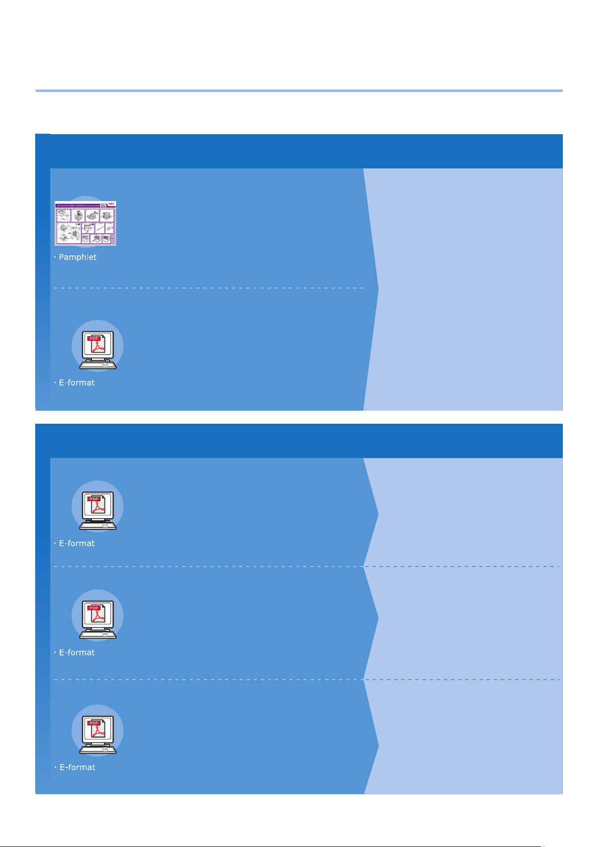
Set-up Guide
This guide uses illustrations to explain the
methods from opening the box to installation.
For the advanced setup guide, see the "Basic".
Preparing the printer to print
Basic (This manual)
This guide describes the precautions for safe
use of the device. Make sure to read before use.
Further, basic uses from the device installation
methods to initial printing are also explained.
The device functions are described in the
appendix.
• Checking the product
• Parts nomenclature and functions
• Using the device to its fullest
• Installing the device
• Turning ON and OFF the power supply
• Test printing using the printer only
• Connecting to a PC
• Paper
• Printing
• Paper ejection
• Setting Power Save mode
• Setting auto power OFF
• Checking the print quantity,
consumables, remaining maintenance
unit quantity, and remaining service life
• Cancelling a print job
• Adding printers using LPD protocols
(TCP/IP)
• Table of control panel menu items
• Basic Windows procedures
• Printer specifications
Step
Read these guides as necessary
2
Try using various functions
Advanced
This guide explains the various paper print methods
and how to use useful functions. Read to optimize the
printing environment or to adjust the color, etc., using
the enclosed utility software.
Further, this guide also explains the items that can be
set from the control panel, and the network settings.
Read for any points that are not understood, or for maintenance
Troubleshooting/Daily
Maintenance Manual
This manual explains the procedures for paper jams, and
troubleshooting method if an error message is displayed. This
manual also explains daily maintenance such as now to replace
consumables and maintenance units, and cleaning, etc.
Separate Volume Spot Color Guide
This guide explains how to check the printer
drivers, and how to print using Spot Color.
Make sure to read before use.
• Useful print functions
• Adjusting the color
• Using utility software
• Network settings
•
Checking and changing printer settings
using the control panel
• Troubleshooting
• Maintenance
• Consumables, maintenance products,
options, color management server,
etc.
• Control panel explanation
• Checking the printer drivers
• Table of printer driver functions
• Printing on color paper
• Printing on transparent film
• Specifying and printing Spot Color
toner using the applications
• Fine-tuning white
- 2 -
Page 3
Reading the Manual
Symbols
Note
These are cautions and restrictions for the correct operation of the device. Make sure to read to avoid misoperation.
Memo
Knowledge of the information before using the device is useful and can act as a reference. Reading is recommended.
Reference
These are the reference pages. Read to learn detailed information and relevant information.
WARNING
Mishandling due to ignoring this display may cause death or serious injury.
CAUTION
Mishandling due to ignoring this display may cause personal injury.
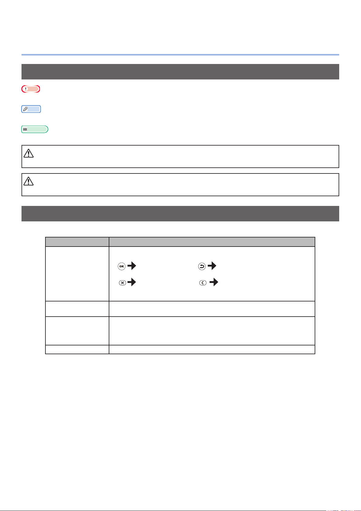
Keys, Buttons, and Symbols
This chapter described the following keys, buttons, and symbols.
Inscription Explanation
The control panel buttons and 10-key pad are described below.
E.g.:
[OK] button [BACK] button
[ ] button/key
[Fn] key [CLEAR] key
Indicates your PC keyboard.
[ ]
" "
> Describes the menu level of the device or PC.
Describes the menu name on the liquid crystal panel.
Describes the PC menus, windows, and dialog box names.
Describes the messages and input text displayed in the liquid crystal
panel.
Describes the le and screen names on the PC.
Describes the reference title.
- 3 -
Page 4

Illustrations
Screens
The device illustrations used herein show the
Pro9541WT model unless otherwise specied.
Illustrations may differ from the actual product.
The images of the control panel and PC used
herein are examples. The images may differ
from actual products and screens.
- 4 -
Page 5

Inscriptions
The following inscriptions are used in this manual.
Pro9541WT → Pro9541
Microsoft
Microsoft
Mac OS X 10.10.5 or later → Mac OS X
The manuals enclosed with the printer use as examples Windows 10 in the case of Windows, and OS X
10.13 in the case of Mac OS X unless otherwise specied.
Depending on the OS and model used, descriptions in this manual may differ.
®
Windows® 10 64-bit Edition operating system → Windows 10 (64bit version)
®
Windows® 10 operating system → Windows 10
- 5 -
Page 6
About the Product Warranty
Every effort has been made to ensure that the information in this document is complete, accurate,
and up-to-date. The manufacturer assumes no responsibility for the results of errors beyond its
control. The manufacturer also cannot guarantee that changes in software and equipment made by
other manufacturers and referred to in this guide will not affect the applicability of the information
in it. Mention of software products manufactured by other companies does not necessarily constitute
endorsement by the manufacturer.
While all reasonable efforts have been made to make this document as accurate and helpful as possible,
we make no warranty of any kind, expressed or implied, as to the accuracy or completeness of the
information contained herein.
All rights are reserved by Oki Electric Industry Co., Ltd. You must not copy, transfer, translate, etc. the
content herein without authorization. You must obtain written permission from Oki Electric Industry Co.,
Ltd. before doing any of the above.
© 2018 Oki Electric Industry Co., Ltd.
OKI is a registered trademark of Oki Electric Industry Co., Ltd.
Energy Star is a trademark of the United States Environmental Protection Agency.
Microsoft, Windows, Windows Server and Windows Vista are registered trademarks of Microsoft
Corporation.
Apple, Macintosh, Mac and Mac OS are registered trademarks of Apple Inc.
Other product names and brand names are registered trademarks or trademarks of their proprietors.
This product complies with the requirements of the Council Directives 2014/30/EU (EMC),
2014/35/EU (LVD), 2014/53/EU (RED), 2009/125/EC (ErP) and 2011/65/EU(RoHS), as
amended where applicable, on the approximation of the laws of the member states relating
to Electromagnetic Compatibility, Low Voltage, Radio & Telecommunications Terminal
Equipment, Energy related Products and Restriction on the use of certain Hazardous
Substances in electrical and electronic equipment.
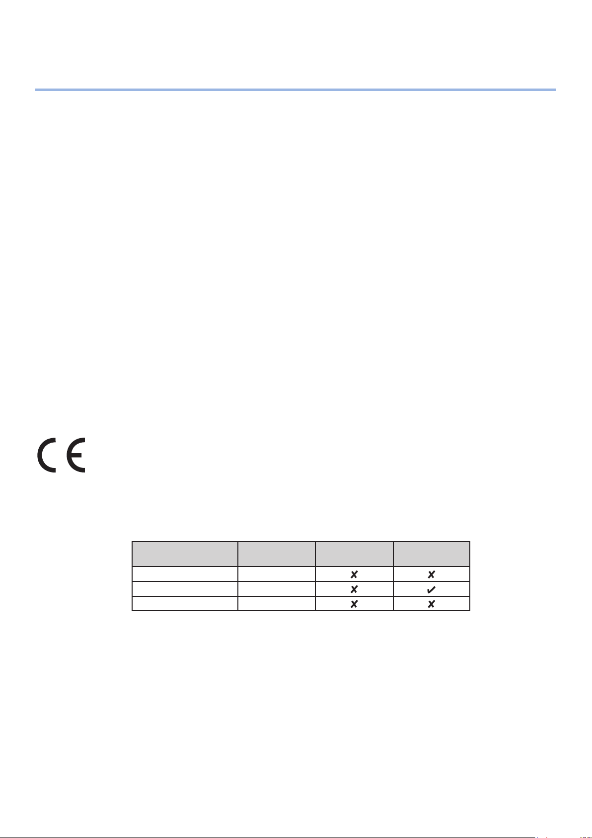
The following cables were used to evaluate this product for EMC directive 2014/30/EU compliance, and
congurations other than this may affect that compliance.
cable type
Power 1.8
USB 5.0
LAN 15.0
length
(meters)
core shield
- 6 -
Page 7

Emergency rst aid
Take care with toner powder:
If swallowed, give small amounts of cold water and seek medical attention. DO
NOT attempt to induce vomiting.
If inhaled, move the person to an open area for fresh air. Seek medical attention.
If it gets into the eyes, ush with large amounts of water for at least 15 minutes
keeping eyelids open. Seek medical attention.
Spillages should be treated with cold water and soap to help reduce risk of
staining skin or clothing.
Environmental information
k
o
.
w
w
w
o
m
c
.
i
/
p
r
i
n
t
i
n
g
/
- 7 -
Page 8
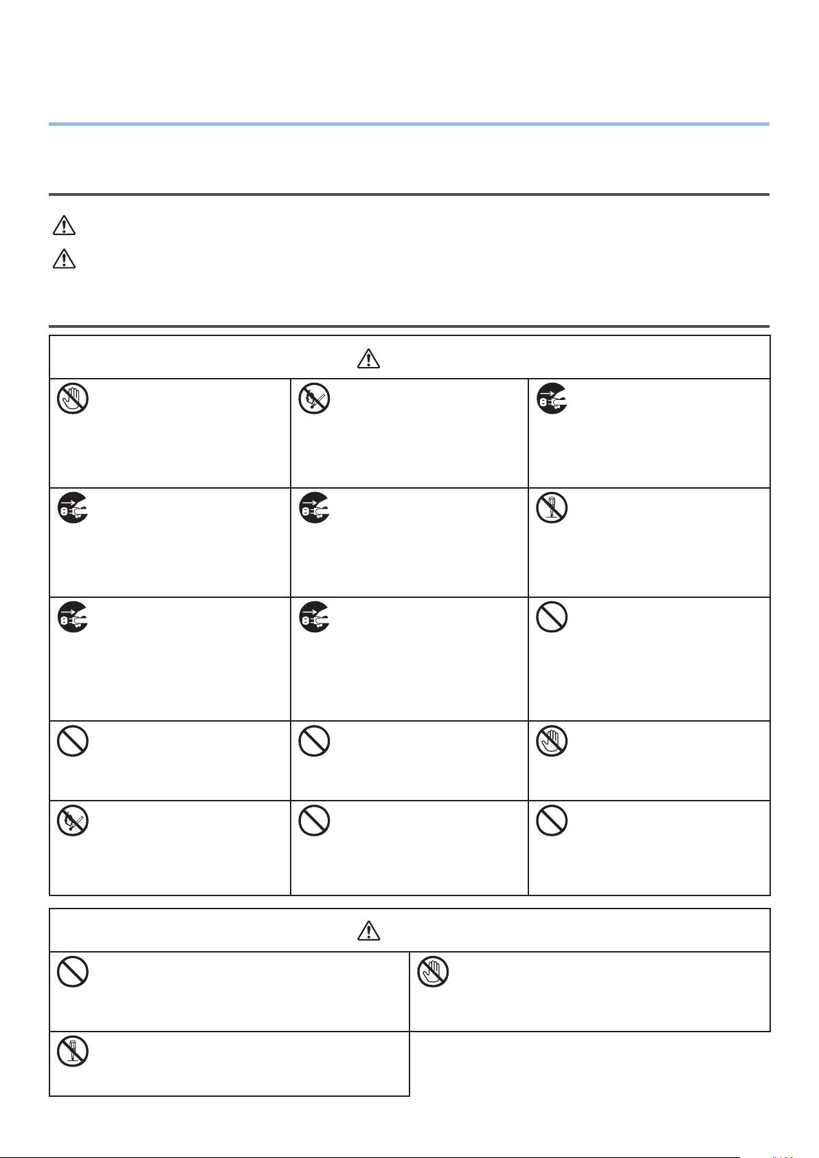
For Your Safety
Read the User’s Manual for your safety before using the product.
Cautions related to safety
WARNING
CAUTION
A warning provides additional information which, if ignored, may result in a risk of personal injury.
A caution provides additional information which, if ignored, may result in equipment malfunction
or damage.
General cautions
Do not touch the safety
switch inside the machine.
Doing so may cause electric
shock when high voltage
occurs. In addition, gears can
rotate, which may result in
personal injury.
Pull the power plug out of
the socket and contact with
a customer’s service center
when a liquid such as water
enters in the internal parts of
the machine.
Failure to do so may cause re.
Unplug the power cord and
contact with a customer’s
service center if the machine
is dropped or the cover is
damaged.
Failure to do so may cause
electric shock and/or re
leading to personal injuries.
Do not insert materials in a
vent hole.
Doing so may cause electric
shock and/or re leading to
personal injuries.
Do not throw toner cartridges
and image drum cartridges
into re. Doing so may cause
dust explosion leading to
burns.
WARNING
Do not use an inammable
spray near the machine.
Doing so may cause re
since there is an area heating
up within the machine.
Pull the power plug out of the
socket and remove foreign
materials such as clips when
they fall inside the machine.
Failure to do so may cause
electric shock and/or re
leading to personal injuries.
Unplug the power cord
periodically to clean plug blades
and root section between
the blades. If the power plug
remains inserted for a long time,
the root section will get dusty,
and the plug may be shorted
out, which may cause re.
Do not put a cup with liquids
such as water on the machine.
Doing so may cause electric
shock and/or re leading to
personal injuries.
Do not use a power cord, a
cable, or a ground wire other
than those that are indicated
in User's Manual.
Doing so may cause re.
Pull the power plug out of
the socket and contact with a
customer’s service center when
the cover is unusually hot,
smoking, giving off questionable
odour, or making a strange noise.
Failure to do so may cause re.
Do not operate and/or
disassemble the machine
other than that directed in
User's Manual.
Doing so may cause electric
shock and/or re leading to
personal injuries.
Do not clean spilled toner with
a vacuum cleaner.
If cleaning spilled toner with a
vacuum cleaner, it may catch
re due to the sparks from
electric contact.
Toner spilled on the oor should
be wiped off with wet cloth.
Do not touch the fuser and
other parts when opening the
cover of the machine.
Doing so may cause burns.
The operation of using UPS
(uninterruptible power source)
or inverters is not guaranteed.
Do not use uninterruptible
power source or inverters.
Doing so may cause re.
CAUTION
Do not come closer to the paper’s exit area when
the power is turned on, while printing.
Doing so may result in personal injury.
Do not disassemble or forcibly open the image
drum or toner cartridge. It may scatter the
toner, which people may inhale or may stain
clothes and hand.
- 8 -
Do not touch a damaged liquid-crystal display.
If liquid (liquid crystal) leaked from the liquid-
crystal display gets into the eyes or mouth, ush
with large amount of water. Follow the direction
from a doctor if necessary.
Page 9

Contents
Manual Conguration ...............................................................................2
Contents
Reading the Manual
Symbols .................................................................................................................. 3
Keys, Buttons, and Symbols
Illustrations
Screens
Inscriptions
............................................................................................................. 4
................................................................................................................... 4
.............................................................................................................. 5
.................................................................................3
....................................................................................... 3
About the Product Warranty .....................................................................6
Emergency rst aid
Environmental information
For Your Safety
Cautions related to safety .....................................................................................................8
General cautions
.................................................................................7
.......................................................................7
.......................................................................................8
.................................................................................................................8
Viable with Pro9541WT .......................................................................... 13
1. Before use ........................................................................... 17
Checking the product .............................................................................17
Checking the Package Contents ................................................................................ 17
Parts Nomenclature and Functions ........................................................... 18
Main Unit ............................................................................................................... 18
Front/Right Side ................................................................................................................18
Back/Left Side
Printer Interior ....................................................................................................... 20
Front Interior .................................................................................................................... 20
Right Side Interior
Left Side Interior
Interface
Control Panel ......................................................................................................... 24
Main Control Panel Features ................................................................................................25
Control Panel Appearance
Adjusting the Control Panel Brightness
Using the 10-Key Pad
Function Numbers Table
..................................................................................................................19
............................................................................................................. 21
............................................................................................................... 22
.......................................................................................................................... 23
................................................................................................... 25
................................................................................. 28
........................................................................................................29
..................................................................................................... 30
Using the Device to its Fullest Extent ....................................................... 31
Options ................................................................................................................. 31
Color management server
........................................................................................ 32
- 9 -
Page 10

Contents
2. Setting Up ........................................................................... 33
Installing the Device ..............................................................................33
Installation Conditions ............................................................................................. 33
Installation Procedure .............................................................................................. 36
Opening the Package and Installation ........................................................................ 36
Opening the Package and Moving the Device .........................................................................36
Mounting Consumables ......................................................................................................39
Setting Paper .................................................................................................................... 43
Mounting the Expansion Tray Unit (Optional) .............................................................. 44
Mounting the Built-in HDD (Optional)......................................................................... 48
Turning ON/OFF the Power .....................................................................50
Power Supply Precautions ........................................................................................ 50
Power Supply Conditions ....................................................................................................50
Connecting Power Cables ......................................................................................... 51
Turning ON the Power Supply ................................................................................... 51
Turning OFF the Power Supply .................................................................................. 52
Test Printing Using the Printer Only ......................................................... 53
Printer Information ................................................................................................. 54
Connecting the PC .................................................................................55
Flow for Installing Drivers on a PC ............................................................................. 55
Operating Environment ............................................................................................ 56
Printer Driver Types ................................................................................................ 56
Connecting Cables .................................................................................................. 57
Connecting Using LAN Cables .............................................................................................. 57
Connecting Using USB Cables .............................................................................................58
Installer Printer Drivers (Windows) ............................................................................ 59
Network Connections ......................................................................................................... 59
USB Connections ............................................................................................................... 64
Installing Printer Drivers (Macintosh) ......................................................................... 66
Network Connections ......................................................................................................... 66
USB Connections ............................................................................................................... 71
Adding Options ....................................................................................................... 72
- 10 -
Page 11

Contents
3. Printing ............................................................................... 75
Paper ..................................................................................................75
Usable Paper Types ................................................................................................. 75
Paper Feed and Output Methods Selectable for Each Paper type .................................... 78
(Landscape) and (Portrait) Icons ........................................................................ 79
Printing from Trays ................................................................................ 80
Setting Paper in Trays 1 to 5 .................................................................................... 80
Printing from Trays .................................................................................................. 81
Printing from the Multi-Purpose Tray ........................................................ 84
Setting Paper in the Multi-Purpose Tray ...................................................................... 84
Setting Paper Using the Control Panel ..................................................................................84
Setting Paper .................................................................................................................... 85
Printing from the Multi-Purpose Tray .......................................................................... 87
Outputting Paper ..................................................................................90
Using the Face-Down Stacker (Print Face Is Down) ...................................................... 90
Using the Face-Up Stacker (Print Face Is Up) .............................................................. 91
4. Basic Device Operations ...................................................... 93
Setting Power Save Mode ....................................................................... 93
Setting Power Save Mode ......................................................................................... 93
Setting the time before the printer enters power save mode ......................................... 94
Setting sleep mode ................................................................................................. 95
Setting the time before the printer enters sleep mode.................................................. 96
Restrictions in sleep mode ........................................................................................ 98
Printer driver utility restrictions ........................................................................................... 98
Network function restrictions ..............................................................................................99
Setup to Turn OFF the Power Supply Automatically .................................. 100
Setting auto power OFF mode .................................................................................100
Setting the time before the printer enters Auto Power Off mode ...................................101
Checking print quantities ..................................................................... 102
Checking Consumables, and Remaining Maintenance Unit Quantities and
Service Life ........................................................................................ 103
Canceling Printing ............................................................................... 104
Adding Printers Using LPD (TCP/IP) Protocols .......................................... 105
Preparations ..........................................................................................................105
Procedure for Adding Printers ..................................................................................105
- 11 -
Page 12

Contents
Appendix ............................................................................... 107
Table of control panel menu items ......................................................... 107
Basic Windows Functions ..................................................................... 114
Displaying the Properties Window ............................................................................114
Displaying the print setup window ............................................................................114
Specications ..................................................................................... 115
Main specications .................................................................................................115
Network interface specications ...............................................................................117
USB interface specications .....................................................................................118
Dimensions ...........................................................................................................119
Index .................................................................................... 121
Contact Us ............................................................................. 125
- 12 -
Page 13

Viable with Pro9541WT
Viable with Pro9541WT
Abundant color matching functions
can be used
The device has functions to
compensate color misalignment and
density using the control panel, and
can adjust the color balance. Further,
colors can be adjusted, the print
results simulated, and the colors
separated and printed using the color
management system from the PC.
It is possible to print from various
applications
The built-in Adobe PostScript3
enable printing from a wide range of
applications.
PostScript3
Various printings are possible
using the convenient functions
Various printings are possible using
the device convenient functions when
printing from a PC.
- 13 -
Page 14
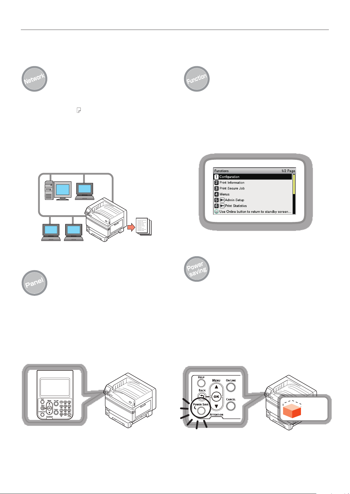
Viable with Pro9541WT
Usable as a network printer
High-quality, high-speed printing is
possible from various applications.
(With A4 , 50 sheets a minute using
color/monochrome printing.) As it
is possible to connect to a network
and print from multiple PCs, ofce
space saving and cost reductions are
achieved.
(This manual page 55)
Functions can be set using the
control panel
Various device functions can be set
such as changing paper size and
network setup from the control panel.
Further, administrator passwords can
also be set using the control panel.
The printer status can be checked,
and error messages and help
displayed, on the control panel
Either "Remaining toner quantity
display" or "Tray information display"
can be displayed in the control panel
standby screen. If an error occurs
in the device, you can work while
checking the control panel messages.
(This manual page 24)
Power consumption is reduced
when the printer is not in use
(Power save mode)
If the device is not used for a xed
period of time, power save mode
starts automatically (power save
mode/sleep mode) to enable power
consumption to be reduced. Press the
[POWER SAVE] button to enter power
save mode manually. When in sleep
save mode, the [POWER SAVE] button
is lit green.
(This manual page 93)
Power
consumption
- 14 -
Page 15

Increasing the quantity of paper
that can be fed
Mounting the optional expansion
tray unit enables the continuous
printing of large quantities and the
printing of different paper sizes to be
implemented smoothly.
(This manual page 31)
Viable with Pro9541WT
Use the help function to check if
you do not understand something
or if trouble occurs when using
the device
Press the [HELP] button on the
control panel to display messages
for resolutions if trouble occurs, and
how to troubleshoot. (Animations will
be displayed depending on the error
details.)
(This manual page 27)
(Troubleshooting/Daily Maintenance
Manual)
- 15 -
Page 16

Viable with Pro9541WT
Memo
- 16 -
Page 17
Checking the product
1. Before use
This chapter explains the package contents of the product and the nomenclature and functions of the parts.
Note
How to set the spot color kit, see the "Separate Volume Spot Color Guide".
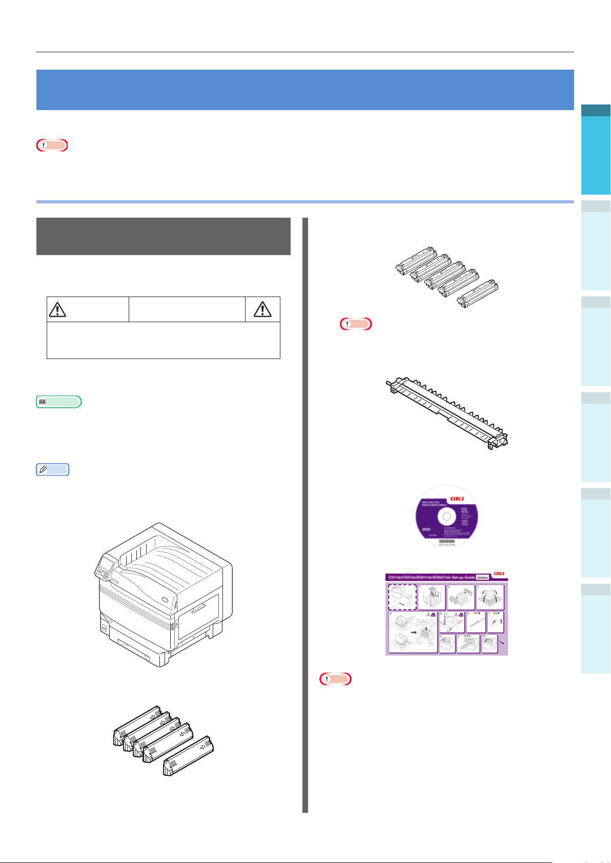
Checking the product
1
2
Checking the Package
Contents
Open the packing case and check the contents of
the box.
CAUTION
The printer weighs approx. 111kg*, so make
sure to use at least 4 people minimum when
lifting.
*: Includes consumables such as the image drum and
toner cartridge, etc.
Reference
See “Opening the Package and Installation” (P.36) for
how to open the package.
See “Mounting the Expansion Tray Unit (Optional)” (P.44)
for the expansion tray.
Memo
A maximum of four additional tray units (trays 2 to 5) can
be mounted.
Printer Unit
There is a risk of injury.
Image drum (One each of black, yellow,
magenta, cyan, and white)
Note
The image drum is set inside the device at the
factory.
Transfer Roller Unit
Software DVD-ROM
Setting Up
3
Printing
4
Basic Device Operations
AppendixBefore use
Toner cartridge (One each of black, yellow,
magenta, cyan, and white)
Set-up Guide
Index
Note
LAN cables, USB cables, and hubs are not included with
the printer. Prepare them separately.
The packing case and buffer material are required when
shipping the device. Do not discard them, but store them
safely.
- 17 -
Page 18

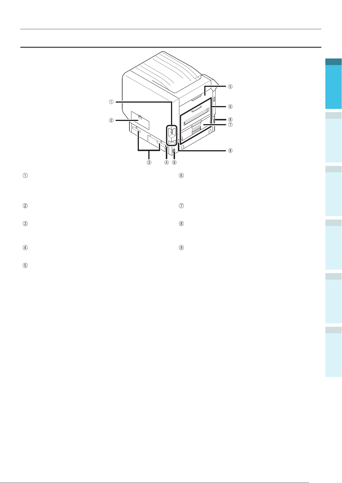
Parts Nomenclature and Functions
Parts Nomenclature and Functions
1
Main Unit
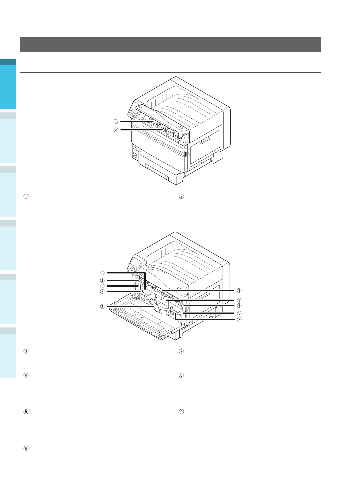
Front/Right Side
2
Setting Up
3
Printing
4
Basic Device Operations
Toner Cover
Open this to replace the toner cartridge.
Control Panel
Displays the device status and menus, and sets the
AppendixBefore use
functions.
“Control Panel” (P.24)
Front Lamp
Flashes when receiving data and while in power save.
Front Cover
Open this to remove the image drum, waste toner
box, and belt unit.
Index
Power Switch
You can turn ON and OFF the power supply when
the main power switch is ON.
Cancel the OFF mode.
Tray 1/Paper Cassette
This is the paper tray mounted as standard. Plenty of
paper can be set at one time.
Set the print surface face-down.
Face Down Stacker
The printed sheets are placed printed-side down and
discharged.
Right Side Cover
Open this to replace the multi-purpose tray feed
roller, and to clear paper jams.
Tray Side Cover
Open to clear paper jams from trays 1 to 5.
Carrying Handles
Hold these at the same time as the carrying lever
when carrying the device.
Carrying Lever
When carrying the device, pull out this lever, and
hold the carrying handles at the same time.
Opener
Open the right side cover.
Spot Color Duct
- 18 -
Page 19
Back/Left Side
Interface
There are a LAN (network) interface connector and a
USB interface connector. See “Interface” (P.23) for
the interfaces.
Parts Nomenclature and Functions
Exit Unit
Open this when replacing the fuser unit or transfer
roller unit, or to clear paper jams.
1
2
Setting Up
3
Printing
Access Cover
Open this when mounting the optional built-in HDD.
Carrying Handles
Hold these at the same time as the carrying lever
when carrying the device.
Power Connector
Connect the enclosed power cable here.
Left Side Cover
Open this to clear paper jams.
Duplex Unit
This device does not support duplex printing.
Carrying Lever
When carrying the device, pull out this lever, and
hold the carrying handles at the same time.
Main Power Switch
Turns ON and OFF the device main power supply.
4
Basic Device Operations
AppendixBefore use
Index
- 19 -
Page 20
Parts Nomenclature and Functions
Printer Interior
1
Front Interior
2
Setting Up
3
Printing
Toner Cartridge
The remaining toner quantity is normally displayed
when "Display remaining toner quantity" has been
set using the control panel standby screen.
4
Basic Device Operations
AppendixBefore use
Index
The toner cartridge is a consumable.
Belt Unit
This device copies the toner to the paper.
The belt unit is a replaceable maintenance part.
Slot
Set the toner cartridge here.
“Mounting Consumables” (P.39)
Handle
Hold this handle when removing the belt unit.
Lock Lever Knob
Secures the belt unit.
Belt Unit Lock Lever
Secures the belt unit.
Belt Unit Lever
Secures the belt unit.
Image Drum/Slot
The image drum is set in the slot.
The image drum is set inside the printer main unit
before shipment from the factory.
The image drum is a consumable.
Waste Toner Box
This box holds the waste toner.
When the waste toner box is full, a message is
displayed on the control panel. The waste toner box
is a replaceable maintenance part.
- 20 -
Page 21
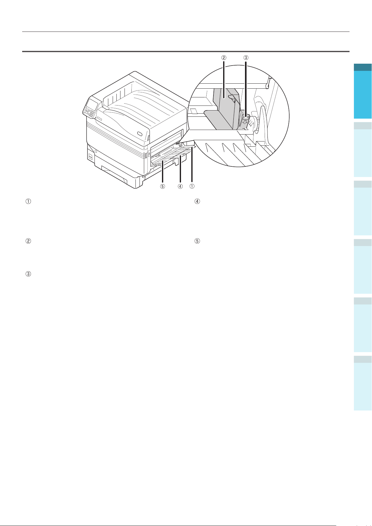
Right Side Interior
Parts Nomenclature and Functions
1
2
Setting Up
3
Multi-purpose Tray/MP Tray
You can print on various papers.
Further, use when printing to the topside of the
paper that has been set. Set the paper size using the
control panel when using as a regular tray.
Paper Guide
Stabilizes the paper by adjusting the paper guide to
the width of the paper to be printed.
Set Lever
Move the paper guide left and right while pulling the
lever towards you when adjusting the paper guide to
the width of the paper. The paper guide is secured
when the set lever is returned to its original position.
Auxiliary Supporter
Maintains the paper when paper has been set in the
multi-purpose tray.
Paper Supporter
Sets the paper to be printed in the multi-purpose
tray.
Sets the print surface face-up.
Printing
4
Basic Device Operations
AppendixBefore use
Index
- 21 -
Page 22
Parts Nomenclature and Functions
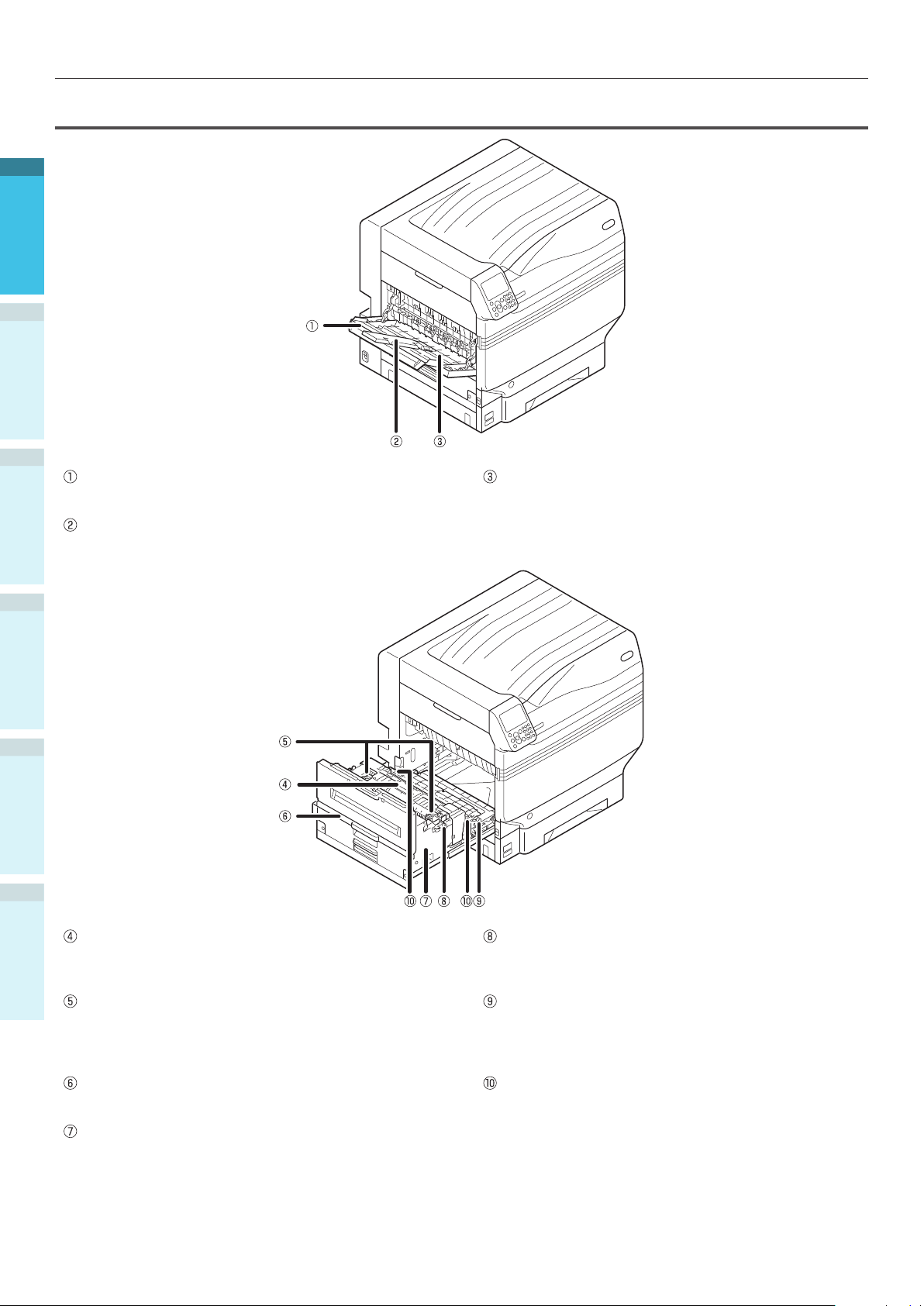
Left Side Interior
1
2
Setting Up
3
Face Up Stacker
Open the stacker to set and eject the paper face-up.
Printing
Auxiliary Supporter
Secures so that the ejected paper does not droop.
Paper Supporter
Secures the paper ejected to the face-up stacker.
4
Basic Device Operations
AppendixBefore use
Index
Fuser Unit
This unit xes the toner to the paper.
The fuser unit is a replaceable maintenance part.
Fuser Unit’s Jam Release Lever
Pull up this lever when a paper jam occurs in the
fuser unit.
Fuser Unit’s Lock Lever
Secures the fuser unit.
Transfer Roller Unit
Transfers the toner to the paper.
The transfer roller unit is a replaceable maintenance
part.
Exit Unit Knob
Pull this knob towards you, and pull out the exit unit.
Exit Unit
The fuser unit, transfer roller unit, and duplex print
unit are mounted to this unit.
Transfer Roller Unit’s Lock Lever
Secures the transfer roller unit.
- 22 -
Page 23
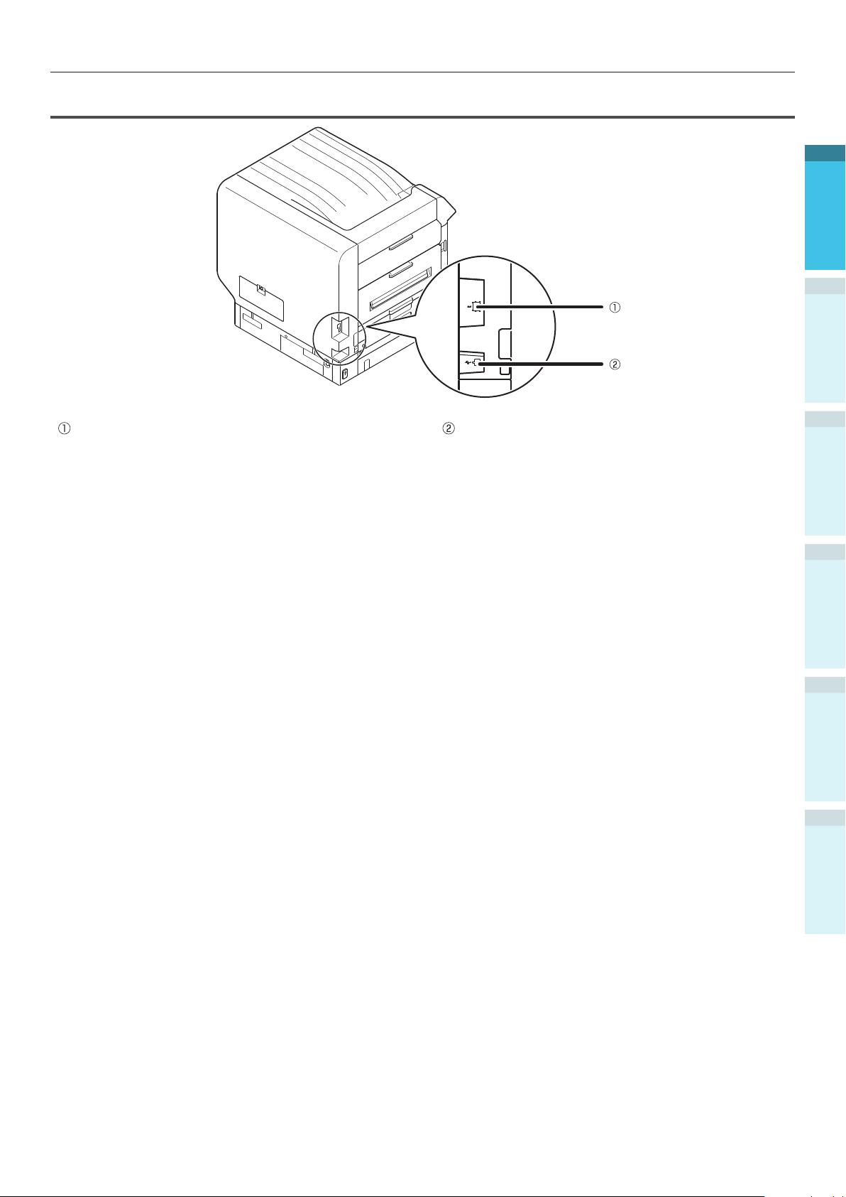
Interface
Parts Nomenclature and Functions
1
2
Setting Up
LAN (network) Interface Connector
Connects the LAN cable.
USB Interface Connector
Connects the USB cable.
3
Printing
4
Basic Device Operations
AppendixBefore use
- 23 -
Index
Page 24

Parts Nomenclature and Functions
Control Panel
1
2
Setting Up
3
Printing
Liquid crystal panel
Displays the device status and menus.
There are two types of standby screen: "Remaining
toner quantity display" and "Tray information
4
Basic Device Operations
display".
[HELP] button
Displays the help screen.
Lit orange when help messages can be referenced,
such as explanations of the error that has occurred
or the cancellation procedure.
ATTENTION lamp
Displays the device status.
Normally OFF.
Lit or ashes orange if an error occurs.
Scroll button (MENU button)
Displays the menu screen to select an item, and
then scrolls up (or down) one page.
Can be used to enter numbers in the numerical
input screen.
[BACK] button
Returns to the previous page.
AppendixBefore use
Index
[OK] button (MENU button)
Determines the selected item and set values.
[POWER SAVE] button
Turns ON and OFF power save mode.
Cancels sleep mode.
[ON LINE] button
Switches between online and ofine.
Lit green when online, and OFF when ofine.
Ten-key pad (1 to 0, *, C)
Use to enter numerical values and passwords.
Press the [*] ([Fn]) key in the standby screen to
display the "function number input" screen, and to
enter menu items directly.
[CANCEL] button
Use to cancel a print, or to cancel the settings.
- 24 -
Page 25
Parts Nomenclature and Functions
Main Control Panel Features
The control panel can be used to check the device status and implement various device functions.
The toner cartridge can be replaced while viewing the liquid crystal display on the control panel.
Further, you can also perform operations while checking the messages displayed on the liquid crystal
panel if paper jams or device malfunctions occur.
Reference
See the control panel menus table “Table of control panel menu items” (P.107).
1
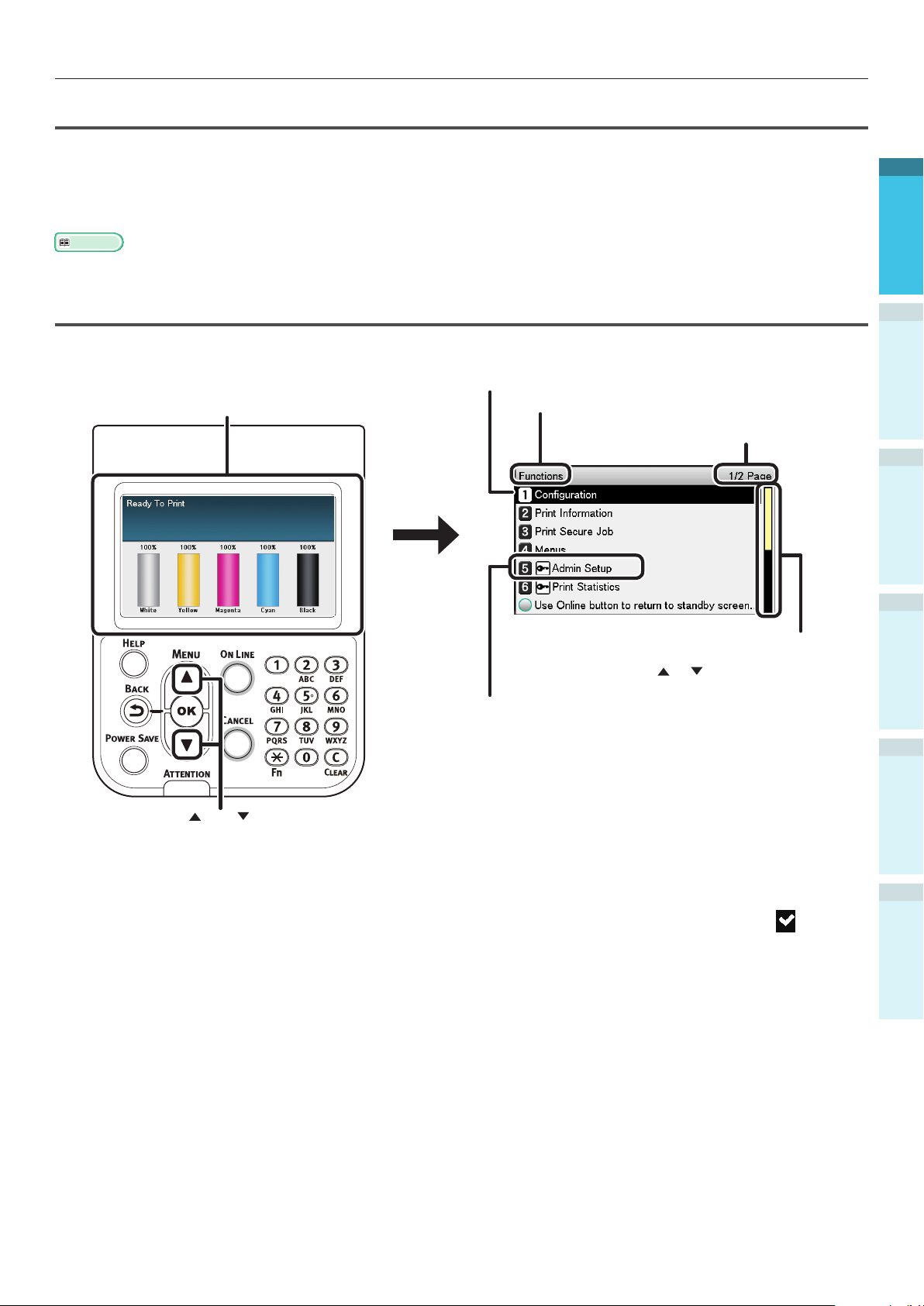
Control Panel Appearance
This section explains the main control panel operations and control panel appearance.
There are two types of standby screen: "Remaining
toner quantity display" and "Tray information display".
The color display of the selected item is inverted.
The name of the menu that is displayed.
Displays the number of pages in the menu
displayed on the liquid crystal panel.
If there is a scroll bar, there are items that are
not displayed in the liquid crystal panel. Press
the scroll button
A password must be entered to display the [Admin
Setup]. Enter the administrator password (factory
setting is "aaaaaa") in the password input screen.
or to display them.
2
Setting Up
3
Printing
4
Basic Device Operations
Press the scroll button or the to display the "Functions"
menu screen as shown on the right.
If there is a selection menu at the next level or set values for an item, select the item and press the
[OK] button to display the next screen.
If a set value is displayed, press the [OK] button to conrm the value that has been set. (
is
displayed to the left of the value.)
AppendixBefore use
Index
- 25 -
Page 26

Parts Nomenclature and Functions
Standby Screen
There are two types: "Remaining toner quantity
display" and "Tray information display".
1
Use the following procedure to switch the
standby screens.
Press either the scroll button or
1
on the control panel to display the
"Functions" screen.
2
Setting Up
3
Printing
4
Basic Device Operations
Press the scroll button several times
2
to select the [Admin Setup], and then
press the [OK] button.
Press the scroll button several times
5
to select [Panel Setup], and then press
the [OK] button.
Press the scroll button several times
6
to select the [Idle Display], and then
press the [OK] button.
To display the "remaining toner
7
quantity" in the standby screen, select
[Toner Gauge], and then press the [OK]
button.
To display the "tray information", select
[Paper Size], and then press the [OK]
button.
Press the [ON LINE] button to return to
8
the standby screen.
3
AppendixBefore use
Index
4
Use the 10-key pad to enter the
administrator password.
The default factory-set password is
"aaaaaa". Press the [OK] button after
entering each individual character.
Press the [OK] button.
- 26 -
Page 27
Parts Nomenclature and Functions
Error Screen
If a printer error occurs, the maintenance lamp
will either turn ON or ash, and a message will
be displayed in the liquid crystal panel.
Depending on the error, the error countermeasure
and animations may be displayed in the liquid
crystal panel in addition to the message.
Reference
"Troubleshooting/Daily Maintenance Manual"
Press the control panel buttons in the error
screen to set the device to the following
statuses.
[POWER SAVE] button:
The printer will enter power save mode. Press
the [POWER SAVE] button when the device is
in power save mode to return to the standby
screen.
[HELP] button:
Press the [HELP] button when it is lit to display
the relevant help message for the error that is
currently displayed.
[OK] Button:
In the case of errors for which the error message
vanishes when the [OK] button is pressed, the
printer will return to the standby screen.
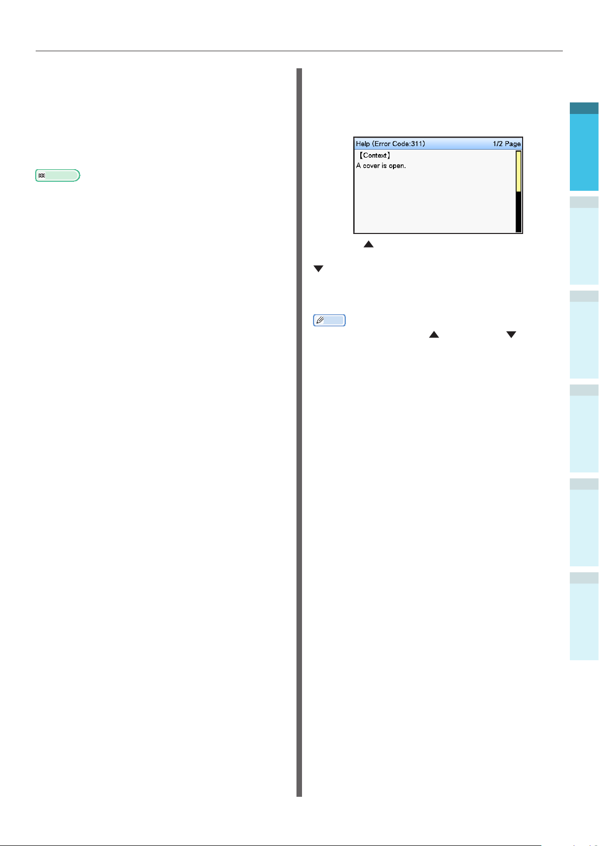
Help Screen
Press the [HELP] button to display the help
screen. Further, press the [HELP] button when it
is lit to display the relevant help message for the
error that is currently displayed.
Press the scroll button displayed in the help
screen to scroll to the previous page. Press the
scroll button to scroll to the next page.
To close the help screen, press the [HELP] button
again.
Memo
Press and hold either the scroll button or to scroll
through the pages at approx. 0.5-second intervals.
The help screen can also be closed by pressing the [BACK]
button, [ON LINE] button, or [CANCEL] button.
1
2
Setting Up
3
Printing
4
Basic Device Operations
[ON LINE] button:
In the case of errors for which the error message
vanishes when the [ON LINE] button is pressed,
the printer will return to the standby screen.
[CANCEL] button:
The following errors can be cancelled.
MPTray Empty
Change [MEDIA_SIZE] [MEDIA_TYPE] in
[TRAY]
[TRAY] Empty
Check Paper in [TRAY]
Paper Size Error
Change [MEDIA_SIZE] [MEDIA_TYPE] in
MPTray
The print data size is too large to store it into
printer memory
Toner Empty
Multiple sheets of paper were fed at once
AppendixBefore use
Index
Paper cassette is not in [TRAY]
Feed print job manually
- 27 -
Page 28

Parts Nomenclature and Functions
Adjusting the Control Panel
Brightness
Use the following procedure to adjust the
1
brightness of the liquid crystal panel.
Memo
The brightness (backlight) of the liquid crystal panel can
be set individually for during control panel operations and
when in power save mode.
2
Setting Up
3
Printing
4
Basic Device Operations
Press either the scroll button or
1
on the control panel to display the
"Functions" screen.
Press the scroll button several times
2
to select the [Admin Setup], and then
press the [OK] button.
Select [Panel Setup], and press the [OK]
4
button.
When adjusting the brightness for
5
during control panel operations, select
[Panel Brightness During Operating],
and press the [OK] button.
When adjusting the brightness for when in
power save, select [Panel Brightness While
Power Save], and press the [OK] button.
AppendixBefore use
3
Index
Use the 10-key pad to enter the administrator
password. The default factory-set password is
"aaaaaa". Press the [OK] button after entering
each individual character.
Press the [ON LINE] button to return to
6
the standby screen.
- 28 -
Page 29
Parts Nomenclature and Functions
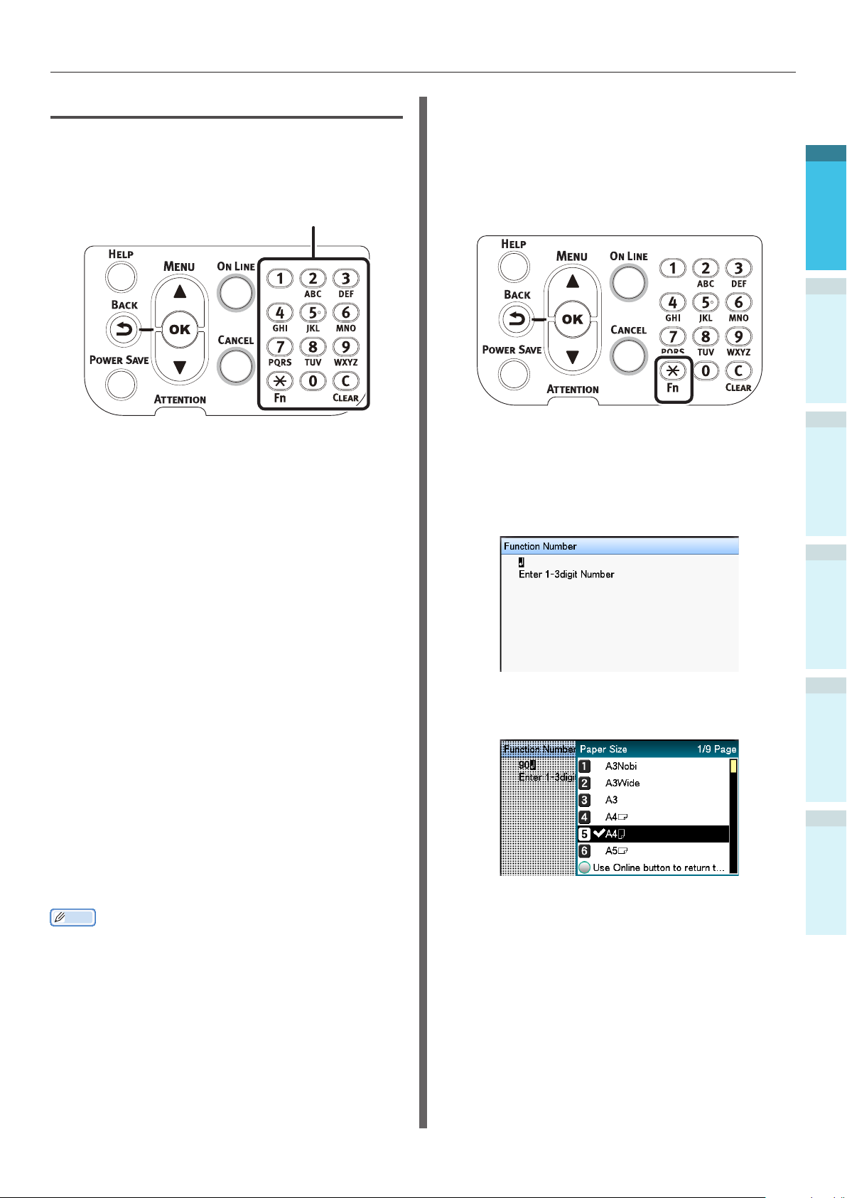
Using the 10-Key Pad
Use to input alphanumeric characters.
The characters that can be entered when each
key is pressed, and the toggling of the input
characters, are described below.
10-key
[1] 1
[2] a → b → c → 2 → a
[3] d → e → f → 3 → d
[4] g → h → i → 4 → g
[5] j → k → l → 5 → j
[6] m → n → o → 6 → m
Function Number Input Screen
When "Ready To Print" is displayed in the
standby screen, press the [Fn] key and then
press the desired number to display the relevant
menu item.
Press the [Fn] key.
1
The function number input screen will
2
be displayed, so use the 10-key pad
to enter the (3-digit) menu number to
be displayed, and then press the [OK]
button.
1
2
Setting Up
3
Printing
4
Basic Device Operations
[7] p → q → r → s → 7 → p
[8] t → u → v → 8 → t
[9] w → x → y → z → 9 → w
[0] 0
The following two key functions are as described
below.
[Fn] key:
Use to display the function number shortcut.
(Enabled when the standby screen is displayed.)
[CLEAR] key:
Conceals each character individually when
entering a password.
Memo
If entering "abc", press the buttons in the
following order: [2]→[OK] button→[2]→[2]→[OK]
button→[2]→[2]→[2]→[OK]
The menu will be displayed, so check or
3
change the set values.
AppendixBefore use
Index
- 29 -
Page 30
Parts Nomenclature and Functions
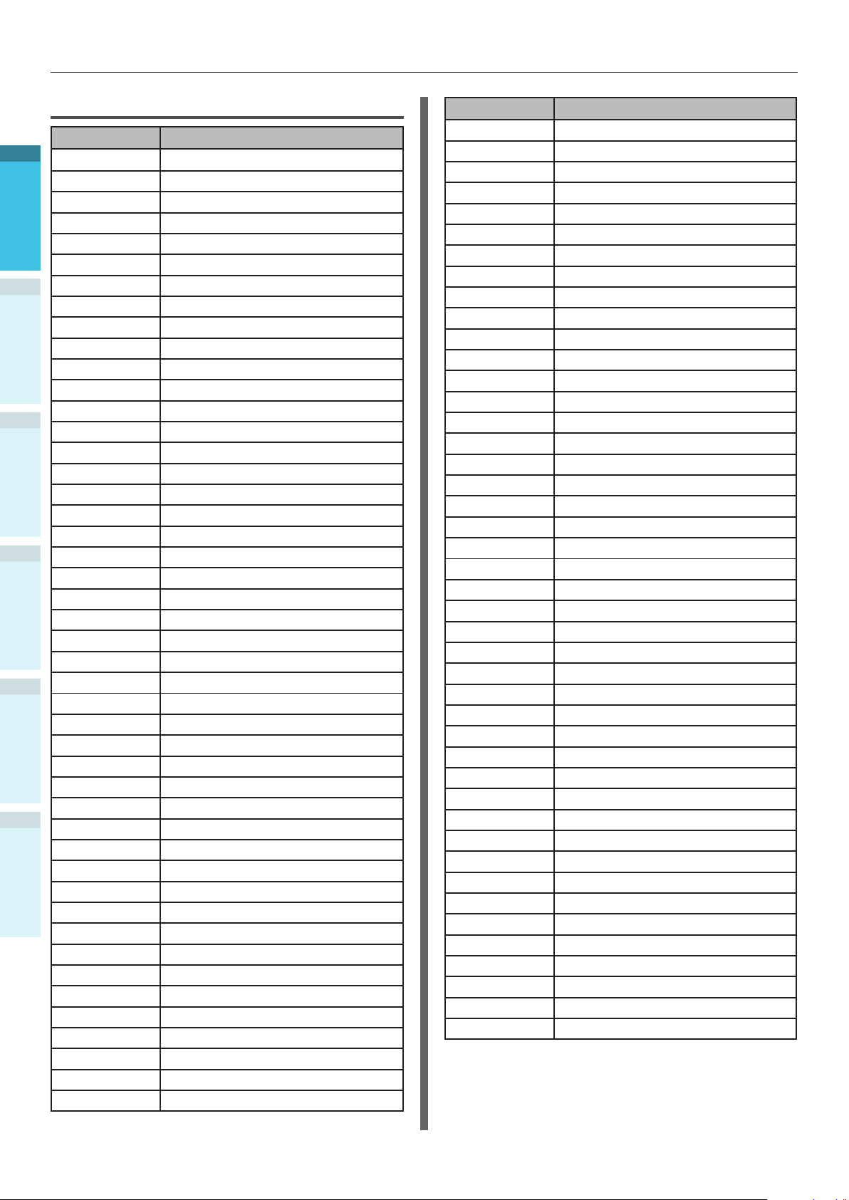
Function Numbers Table
Function No. Function No. Menu Item
1
1 Print Secure Job (Encrypted Job)
2 Print Secure Job (Stored Job)
10 Paper Size (Tray 1)
11 X Dimension (Tray 1)
12 Y Dimension (Tray 1)
13 Media Type (Tray 1)
14 Media Weight (Tray 1)
2
15 A3Nobi Paper (Tray 1)
Setting Up
16 Legal14 Paper (Tray 1)
17 A5LEF/A6 Paper (Tray 1)
18 A5SEF Paper (Tray 1)
19 Other Size (Tray 1)
20 Paper Size (Tray 2)
3
21 X Dimension (Tray 2)
22 Y Dimension (Tray 2)
Printing
23 Media Type (Tray 2)
24 Media Weight (Tray 2)
25 A3Nobi Paper (Tray 2)
26 Legal14 Paper (Tray 2)
4
27 A5LEF/A6 Paper (Tray 2)
Basic Device Operations
28 A5SEF Paper (Tray 2)
29 Other Size (Tray 2)
30 Paper Size (Tray 3)
31 X Dimension (Tray 3)
32 Y Dimension (Tray 3)
33 Media Type (Tray 3)
34 Media Weight (Tray 3)
AppendixBefore use
35 A3Nobi Paper (Tray 3)
36 Legal14 Paper (Tray 3)
37 A5LEF/A6 Paper (Tray 3)
38 A5SEF Paper (Tray 3)
39 Other Size (Tray 3)
40 Paper Size (Tray 4)
41 X Dimension (Tray 4)
Index
42 Y Dimension (Tray 4)
43 Media Type (Tray 4)
44 Media Weight (Tray 4)
45 A3Nobi Paper (Tray 4)
46 Legal14 Paper (Tray 4)
47 A5LEF/A6 Paper (Tray 4)
48 A5SEF Paper (Tray 4)
49 Other Size (Tray 4)
50 Paper Size (Tray 5)
51 X Dimension (Tray 5)
52 Y Dimension (Tray 5)
53 Media Type (Tray 5)
Function No. Function No. Menu Item
54 Media Weight (Tray 5)
55 A3Nobi Paper (Tray 5)
56 Legal14 Paper (Tray 5)
57 A5LEF/A6 Paper (Tray 5)
58 A5SEF Paper (Tray 5)
59 Other Size (Tray 5)
80 Paper Feed Tray
90 Paper Size (MPTray)
91 X Dimension (MPTray)
92 Y Dimension (MPTray)
93 Media Type (MPTray)
94 Media Weight (MPTray)
95 Tray Usage (MPTray)
100 Print Information (Conguration)
101 Print Information (Network)
102 Print Information
103 Print Information (Error Log)
200 Power Save Time
201 Sleep Time
202 Auto Power Off Time
210 Error Report
220 Print Position Adjust (MPTray)
221 Print Position Adjust (Tray 1)
222 Print Position Adjust (Tray 2)
223 Print Position Adjust (Tray 3)
224 Print Position Adjust (Tray 4)
225 Print Position Adjust (Tray 5)
230 Paper Black Setting
231 Paper Color Setting
232 Trans. Black Setting
233 Trans. Color Setting
234 SMR Setting
235 BG Setting
236 Drum Cleaning
237 Hex Dump
238 Transfer Roller Cleaning
300 Adjust Density
301 Adjust Registration
302 Print Color Tuning Pattern
310 Cyan Density
311 Magenta Density
312 Yellow Density
313 Black Density
314 White Density
(Usage Report)
- 30 -
Page 31

Using the Device to its Fullest Extent
Options
The following options are supplied for the device.
Expansion tray units (trays 2/3/4/5)
Using the Device to its Fullest Extent
1
2
Setting Up
3
Printing
Expansion tray unit
(Expandable up to 2 levels)
(N36110A)
Note
If expanding from level 3 upwards, use a large-capacity expansion tray unit.
Expansion tray unit with casters
(N36130A)
Built-in HDD
Large-capacity expansion tray unit
(3 trays in one, with casters)
(N36120A)
4
Basic Device Operations
AppendixBefore use
Index
- 31 -
Page 32

Using the Device to its Fullest Extent
Color management server
Recommended for users who want greater color management response and advanced Spot Color
1
adjustment.
Fiery® XF Server Option
2
Setting Up
3
Printing
4
Basic Device Operations
AppendixBefore use
Index
Fiery® XF Server Option
- 32 -
Page 33

Installing the Device
2. Setting Up
This chapter explains the methods for setting up the device, and for connecting the device to a PC and
installing the printer drivers.
Note
Customers should also see the "Separate Volume Spot Color Guide".
Reference
See the "Fiery XF Sever Quick Start Guide" for the methods of setting up the color management server.
Installing the Device
For safe and pleasant use of the device, install in a location that satised the "installation environment"
and "installation space" described in the "installation conditions". Further, the conditions also describe
the installation precautions. Make sure to read them before use.
1
Before use
2
Setting Up
3
Installation Conditions
Consider the following environmental conditions
before selecting the device installation location.
Installation Environment
Use in a location where temperature and
humidity are within the following ranges.
Ambient
temperature:
Ambient
humidity:
Max. wet-bulb
temperature:
Memo
Make sure there is no condensation.
If installing in a location where the ambient humidity is
30% or less, use a humidier or static prevention mat.
10ºC to 32ºC
20% to 80%RH (relative humidity)
25ºC
Installation Space
Make sure the area around the device has
the following space, and select a location that
can support the weight of the device before
installing. (The main unit weights is Approx.
111kg*.)
*: Includes consumables such as image drums and toner
cartridges, etc.
Plane view
200mm
1770mm
620mm
1420mm
600mm
Front view
400mm
460mm
4
Basic Device Operations
AppendixPrinting
Index
- 33 -
1040mm
Page 34

Installing the Device
1
Before use
2
Setting Up
3
Front view (with expansion tray mounted)
400mm
1560mm
Installation Precautions
WARNING
Do not install close to high-temperature locations
or naked ames.
Do not install in locations where chemical
reactions occur (e.g., laboratories).
Do not install close to combustible solutions such
as alcohol or thinners, etc.
Do not install within reach of small children.
Do not install in an unstable location (e.g.,
unsteady tables or sloping locations, etc.)
Do not install in humid or dusty locations, or in
locations in direct sunlight.
Do not install in environments with salt air or
corrosive gas.
Do not install in locations with major vibration.
Do not install in locations where the device air
holes are blocked. Use the following illustrations
to check the air hole position.
Top
4
Basic Device Operations
AppendixPrinting
Index
Right
side
Front
- 34 -
LeftBack
Page 35

CAUTION
Installing the Device
Do not install directly on shaggy rugs or carpets.
Do not install in locations with poor air circulation
or ventilation such as sealed rooms, etc.
Make sure of ventilation if using continuously for
long hours in a small room.
Install away from strong magnetic elds and
sources of noise.
Install away from monitors and TVs.
When moving the device, hold the carrying lever
and carrying handles.
The main device weight is approx. 111kg*. When
lifting or moving the device, make sure to use at
least 4 people.
Make sure of the ventilation if printing large
quantities or using the device continuously for
long hours.
*: Includes consumables such as image drums and toner
cartridges, etc.
1
Before use
2
Setting Up
3
4
Basic Device Operations
AppendixPrinting
Index
- 35 -
Page 36
Installing the Device
Installation Procedure
Work according to the relevant procedures and the customer installation conditions. If not mounting
1
any options, skip the reading of the procedures described as "Optional".
Before use
2
Setting Up
3
Opening the Package and Installation
1
Mounting Consumables (P.39)
2
Mounting the Expansion Tray Unit (Optional) (P.44) (Optional)
3
Mounting the Built-in HDD (Optional) (P.48) (Optional)
4
Connecting Using LAN Cable (P.57)
5
Connecting Using USB Cable (P.58)
6
Installing and Connecting the Color Management Server
7
("Server Installation Guide")
Connecting Power Cables (P.51)
8
Connecting to PC (P.55)
9
Adding Options (P.72) (Optional)
10
Printing from Trays (P.81)
11
Printing from the Multi-Purpose Tray (P.87)
(Sold
separately)
Opening the Package and
Installation
4
Basic Device Operations
This section explains the procedure from opening
the package to removing and installing the
product.
Opening the Package and Moving
the Device
Make sure to install in a sufciently robust
AppendixPrinting
location that can support the weight of the
device and its options. Do not install in unstable
locations such as on unsteady tables or slanted
locations, or in locations with strong vibrations.
Doing so risks causing injury due to the device
falling or toppling.
Memo
For device installation locations, see “Installation
Index
Conditions” (P.33).
CAUTION
There is a risk of injury.
The main unit weights are as described below.
With the toner
cartridge and image
drum mounted
Approx. 111kg Approx. 91kg
With the toner
cartridge and image
drum removed
The weight of the device is approx. 111kg*, so
make sure to use at least 4 people to lift.
*: Includes consumables such as image drums and toner
cartridges, etc.
- 36 -
Page 37
Installing the Device
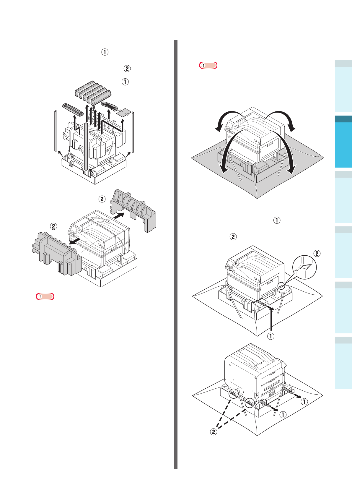
Open the package, and remove the
1
device accessories (
manual, protective equipment, and
shock-absorbing material (
), and enclosed
).
Remove the cover bag enclosing the
2
main printer unit.
Note
Do not remove the tape securing the protective
equipment, paper feed trays, and side covers before
transporting the device to its installation location.
The trays and covers opening during transport may
cause unexpected injury.
Remove the three carrying levers at the
3
bottom of the printer (
the three locations of the carrying
handles (
).
), and check
1
Before use
2
Setting Up
3
4
Basic Device Operations
Note
The packing and protective equipment are used
when shipping the device, so store them carefully.
AppendixPrinting
Index
- 37 -
Page 38
Installing the Device
4
1
Before use
2
Setting Up
3
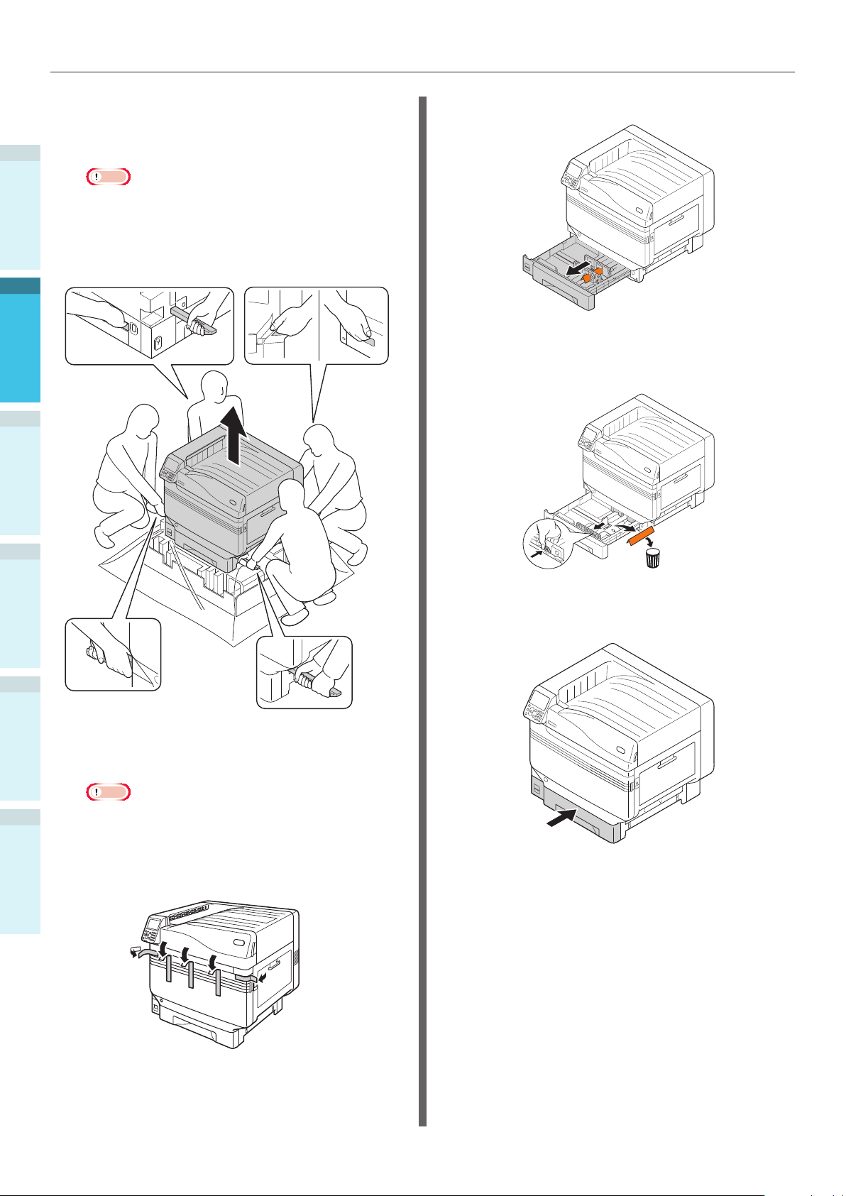
Hold the carrying levers while grasping
the carrying handles, and use at least 4
people to lift and carry simultaneously.
Note
Make sure not hold anywhere other than the
carrying handles, such as the paper feed trays or
side covers, etc. Doing so may cause injury due to
dropping the device.
Make sure to use 4 people min. for lifting and
carrying so there is no back pain, etc.
Pull out the tray 1 paper cassette.
7
Slide the paper guide and take out the
8
sheet retainer.
4
Basic Device Operations
AppendixPrinting
Index
Gently lower the device into its
5
installation location.
Note
Gently and carefully lower the device. There is a
risk of crush injuries to hands, etc.
Peel off the ve protection tapes from
6
the printer main unit.
Return the paper cassette to the tray.
9
- 38 -
Page 39

Installing the Device
Mounting Consumables
Setting the Toner Cartridge
Remove the toner cartridge from its
cover bag.
1
Shake the toner cartridge both
horizontally and vertically.
2
Note
Do not drop the toner cartridge or tap it on the
oor. Doing so may damage the cartridge.
Open the toner replacement cover.
3
Close the toner replacement cover.
5
Remove the image drum stopper
Memo
The image drum is set inside the device at the factory.
Reference
For the methods of replacing the image drum, see
"Troubleshooting/Daily Maintenance Manual", or the device
help.
The stopper is mounted to the image drum in
the device at the factory.
Make sure to use the following procedure to
remove the stopper before use.
Open the front cover.
1
1
Before use
2
Setting Up
3
4
Basic Device Operations
Check the position of the slot that has a label stuck
4
on it with the same letters and colors, and rmly
push the toner cartridge in as far as it will go.
Remove the 5 retainers from the image
2
drum.
AppendixPrinting
Index
- 39 -
Page 40

Installing the Device
3
1
Before use
2
Setting Up
3
Gently raise the (blue) lever ( ), and
remove the image drum (
) while
being careful not to touch the green
cylinder with your hands.
Place the image drum that has been
4
removed onto a at surface covered
with paper, and remove 4 stoppers
(orange) in the direction of the arrows.
4
Basic Device Operations
AppendixPrinting
Index
Note
Do not expose the image drum to direct sunshine
or strong light (approx. 1,500 lux or above). Do not
leave it for more than 5 minutes even under indoor
light.
Be careful not to touch or scratch the image drum
(green cylinder).
- 40 -
Page 41

Installing the Device
Align the (red) arrow labels on the
image drum with the arrows on the
5
device, and gently insert into the slot
and push in rmly all the way while
being careful not to touch the green
cylinder with your hands.
Set the transfer roller unit.
Lift the exit unit opener ( ), and pull
1
out the exit unit.
1
Before use
2
Setting Up
3
Note
Be careful not to touch or scratch the image drum
(green cylinder).
Close the front cover.
6
Raise the lock levers (blue) at both ends
of the transfer roller unit installation
2
location of the exit unit.
4
Basic Device Operations
AppendixPrinting
Index
Reference
This printer requires the Spot Color kit to be set. For details,
see the "Separate Volume Spot Color Guide".
- 41 -
Page 42

Installing the Device
Take out the transfer roller unit from
the package.
3
1
Before use
2
Setting Up
3
The toner used for quality inspection might be adhered to
4
Basic Device Operations
Note
Do not touch sponge of the transfer roller unit.
Memo
the roller surface. The toner on the roller surface will not
affect the performance.
Set the transfer roller unit to the exit
unit.
4
AppendixPrinting
Index
Push both sides of the lock lever (blue)
down.
5
Put the exit unit back into the printer.
6
- 42 -
Page 43

Installing the Device
Setting Paper
This section explains how to set the paper in tray
1 or trays 2/3/4/5.
Memo
In this section, setting paper in tray 1 is used as an
example. Set trays 2 to 5 using the same procedure.
Pull out the tray 1 paper cassette ( ).
1
Set the paper with the print surface
4
face-down.
Note
Do not exceed the " " symbol ( ) on the paper
guide when setting the paper.
1
Before use
2
Setting Up
3
Slide the paper guide ( ) and paper
2
stopper (
paper that has been set.
Thoroughly sort the paper. Carefully
3
align the edges of the paper
horizontally.
) to align to the size of the
Memo
Set so there is no gap between the paper and the
paper guide or paper stopper.
Use the paper guide to secure the
5
paper.
Return the paper cassette to the tray.
6
4
Basic Device Operations
AppendixPrinting
Index
- 43 -
Page 44

Installing the Device
Mounting the Expansion
Tray Unit (Optional)
1
Mount the (optional) expansion tray unit to
Before use
increase the quantity and types of paper that
can be set in the device.
The expansion tray unit has a large-capacity tray
comprising the 1st and 3rd trays.
The device can expand to a maximum of 4 trays
2
(5 including the standard tray).
The expansion trays can be mounted to either
Setting Up
the main printer unit or the expansion tray unit.
Note
If placed on a table, the expansion tray unit can be
expanded to 2 trays (3 including the standard tray).
If placed on a table, the large-capacity expansion tray unit
3
cannot be used.
Expansion tray unit
Expansion tray unit with casters
Mounting the expansion tray unit with
casters to the main printer unit
4
Basic Device Operations
AppendixPrinting
Index
- 44 -
Page 45

Installing the Device
Large-capacity expansion tray unit
Memo
The expanded trays are called tray 2, tray 3, tray 4, and
tray 5.
Expansion
tray unit
Large-capacity
expansion tray
unit
Tray 1 (standard)
Tra y 2
Tra y 3
Tra y 4
Tra y 5
Remove the expansion tray unit from
1
the package, and remove the buffering
and protective materials.
Mount the main printer unit to the
2
expansion tray unit.
Gently lift the main unit using 4 people
min., and align the holes on the base
) to the 2 protrusions ( ) on the
(
expansion tray unit.
Gently place on the other while
matching the main unit to the position
of the vertical lines on the back of the
expansion tray unit.
CAUTION
The weight of the device is approx. 111kg*, so
make sure to use at least 4 people to lift.
*: Includes consumables such as image drums and toner
cartridges, etc.
Note
If the device is connected to a power supply, turn OFF the
device power, and remove the cables. For how to turn OFF
the power supply, see “Turning OFF the Power Supply”
(P.52).
There is a risk of injury.
1
Before use
2
Setting Up
3
4
Basic Device Operations
AppendixPrinting
Index
- 45 -
Page 46

Installing the Device
1
Before use
2
Setting Up
3
Note
If using the expansion tray unit and large-capacity
expansion tray unit, rst mount the expansion tray
unit to the large-capacity expansion tray unit, and then
mount the main printer unit to the expansion tray unit.
Printer
base hole
Protrusion
Push down the lock levers on the
3
casters (x2) at the front of the device
to lock the casters.
4
Basic Device Operations
AppendixPrinting
Index
Protrusion
Loosen the nuts (x2) at the top of the
4
feet on the right of the device.
For the expansion tray unit and large-capacity expansion tray
unit with casters, adjust the caster locks (x2) and feet (x2).
- 46 -
Page 47

Installing the Device
Rotate the nuts and bolts at the bottom
of each foot to lower the feet.
5
When each foot has reached the
ground, tighten the nuts at the top to
6
secure the tray unit.
If moving the printer or replacing consumables
or maintenance units, or setting paper in the
tray, check the following points to prevent the
printer from toppling.
Do not press the front cover when the printer
font cover is open.
Do not press on the cassette from above when
the cassette is pulled out.
1
Before use
2
Setting Up
3
4
Basic Device Operations
Note
When moving the device, rotate and thoroughly lift the
screws on the feet of the large-capacity expansion tray
unit, and move while remote from the ground.
Memo
If mounting the expansion tray unit, it is necessary to implement
“Connecting Cables” (P.57)
Cables” (P.51)
drivers to detect the expansion tray unit.
See
“Adding Options” (P.72)
before making the settings for the printer
and
“Connecting Power
.
AppendixPrinting
Index
- 47 -
Page 48

Installing the Device
Mounting the Built-in HDD
(Optional)
1
Mount the (optional) built-in HDD to increase the
Before use
memory capacity or implement secure printing.
Reference
For the functions required by the HDD, see "Advanced".
2
Setting Up
3
4
Basic Device Operations
Built-in HDD
Turn OFF the device power supply, and
1
remove the cables.
Note
When turning OFF the power supply, make sure
to press the power switch and wait for shutdown
before turning OFF (O) the main power switch.
Reference
“Connecting Power Cables” (P.51)
“Turning OFF the Power Supply” (P.52)
Check that the internal LED lamp ( ) is
3
OFF.
Align the screws (x2) on the built-in
4
HDD to the holes on the device.
AppendixPrinting
Index
Loosen the screws on the access cover
2
at the back of the printer (
open the door (
).
), and
Rotate the screws (x2) in the direction
5
of the arrows to tighten securely.
Connect the HDD connectors to the
6
device.
- 48 -
Page 49
Installing the Device
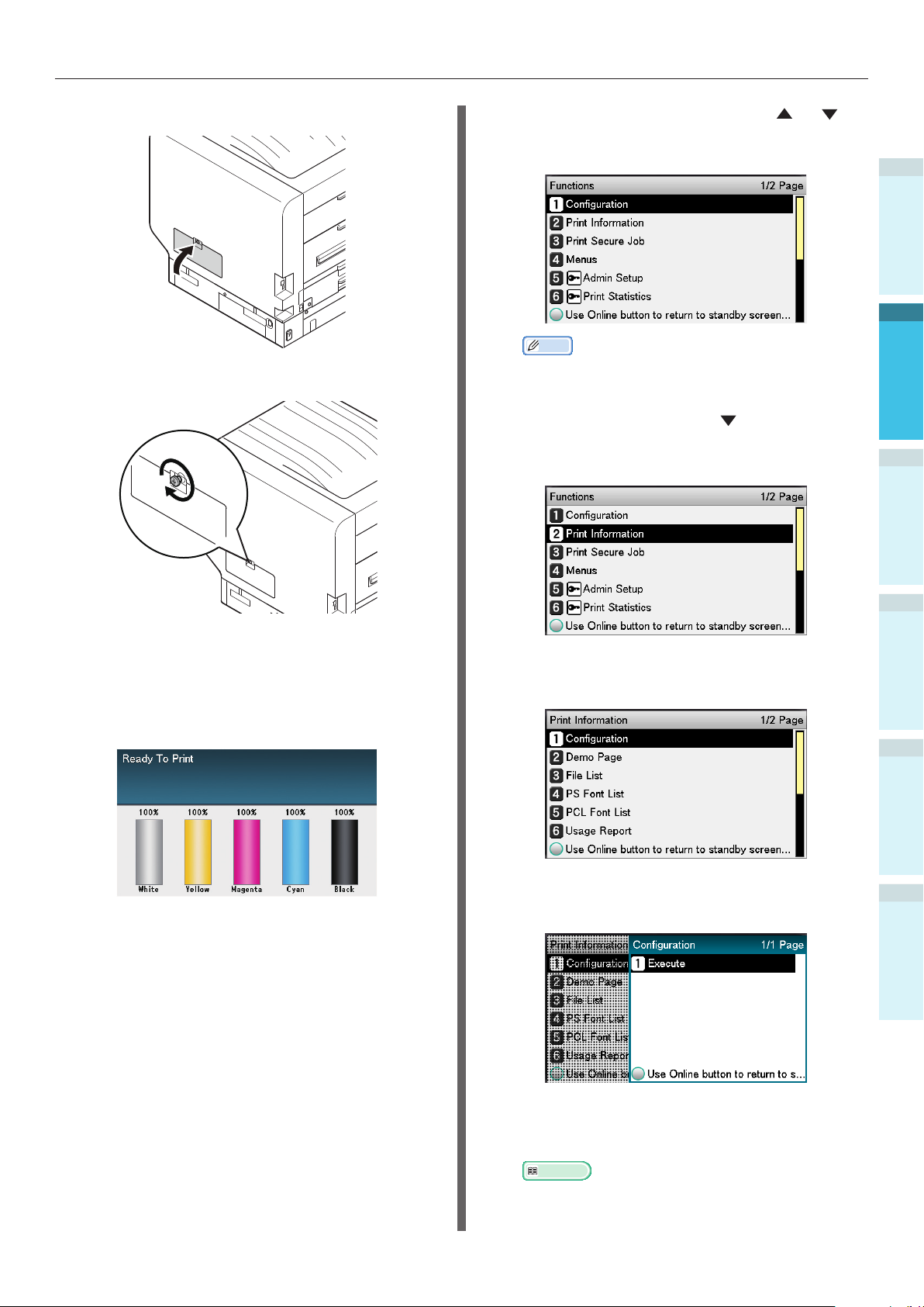
Close the access cover.
7
Tighten the access cover screws.
8
Press either the scroll button
on the control panel to display the
"Functions" screen.
Memo
Print the "Conguration" on A4 size paper. Set A4
size paper in the paper feed tray.
Press the scroll button to select [Print
12
Information], and then press the [OK]
button.
or
1
Before use
2
Setting Up
3
Connect the cables, and turn ON the
9
device power supply.
Check that the standby screen is
10
displayed in the liquid crystal panel.
Print the "Conguration".
11
When the [Conguration] have been
13
selected, press the [OK] button.
When [Execute] has been selected,
14
press the [OK] button.
4
Basic Device Operations
AppendixPrinting
Index
- 49 -
Check that the HDD has been added to
15
the "Conguration".
Reference
“Printer Information” (P.54)
Page 50

Turning ON/OFF the Power
Turning ON/OFF the Power
1
Power Supply Precautions
Before use
There is a risk of getting
an electric shock and/or
causing fire.
2
Setting Up
3
4
Basic Device Operations
AppendixPrinting
Index
WARNING
Be sure to cut off the power supply when
attaching or removing the power supply plug
or the earth wire.
Be sure to connect an earth wire to the
grounding terminal of exclusive use.
Please do not connect with the ground of a
water pipe, a gas pipe, and a telephone wire,
or lightning rod without fail.
Make sure to connect with the ground terminal
before connecting the power cord to the
power supply plug.
Be sure to perform extraction and insertion of
the power cord with a power supply plug.
Insert the power supply plug into the wall
socket securely.
Do not touch the power cord, or machine, if
your hands are wet.
Install the power cord in a location where it will
not be stepped on, and do not place objects on
the power cord.
Do not twist, bind, or knot the power cord.
Please do not use a damaged power cord.
Do not carry out foot wiring.
Do not connect this machine and other electric
products to the same wall socket. If connected
simultaneously with an air-conditioner, a copy
machine, shredder, etc., electric noise may
interfere with operation. When the connection
with the same wall socket is unavoidable,
please use a commercial noise lter or a
commercial noise cut transformer.
Use the attached power cord and insert it
directory with the ground terminal. Do not use
power cords intended for other products with
this machine.
Do not use an extension cord. When use is
unavoidable, use a cord rated higher than 15A.
Use of an extended cord may cause AC
voltage decrease and interfere with normal
operation.
During printing, do not shut off the power
supply or pull out the power supply plug.
When not in use for consecutive holidays or
longterm travel, pull out the power cord.
Do not use the attached power cord for other
products.
Power Supply Conditions
Observe the following power supply conditions.
Current: 110 - 127VAC
(Range 99 - 140 VAC)
220 - 240VAC
(Range 198 - 264VAC)
Power
frequency:
Note
If the power supply is unstable, use a voltage regulator.
The maximum power consumption of the device is 1500W.
Check that there is sufcient voltage capacity.
Operations cannot be assured if using an uninterruptible
power supply (UPS) or inverter. Do not use an
uninterruptible power supply or inverter.
50/60 Hz ± 2%
- 50 -
Page 51
Turning ON/OFF the Power
Connecting Power Cables
Check that the device power supply is
1
turned OFF.
The device is OFF when the main power
switch is in the (O) position.
Secure insert the enclosed power cable
2
into the device power connector.
Turning ON the Power
Supply
Note
Do not turn ON the power supply before the Spot Color kit
has been set.
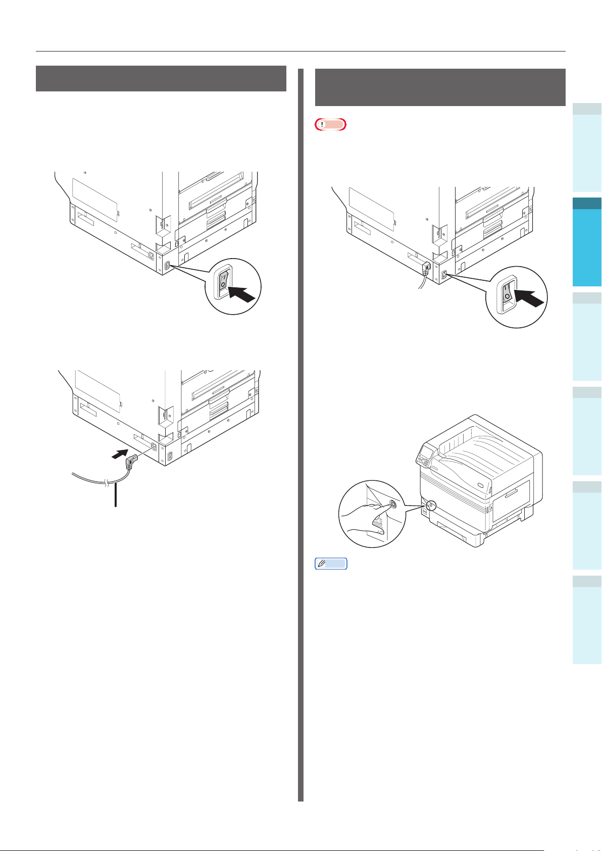
Turn ON (I) the main power switch.
1
ON
Press and hold the power switch for
2
approx. 1s.
1
Before use
2
Setting Up
3
Power cable
Insert the power plug into the power
3
outlet.
When the power supply is ON, the LED
lamp for the power switch will turn ON.
Memo
The "OKI" logo screen will be displayed in the liquid crystal
display of the control panel when the device starts. Wait
a moment until the standby screen is displayed, and the
printing is enabled.
When the power supply is turned ON for the rst time, the
device auto initialization will start. Wait until the standby
screen is displayed in the liquid crystal display on the
control panel.
4
Basic Device Operations
AppendixPrinting
Index
- 51 -
Page 52

Turning ON/OFF the Power
Turning OFF the Power
Supply
1
During normal use, use the following procedure
Before use
to turn OFF the power supply.
Note
Once shutdown has been implemented, it cannot be
stopped. To turn ON the device power supply again, wait
until shutdown has nished, and then turn ON the power
2
Setting Up
3
4
Basic Device Operations
AppendixPrinting
supply.
Press and hold the power switch for
1
approx. 1s.
"Shutting down. Please wait. Power
will turn OFF automatically" will be
displayed in the control panel, and the
power switch LED lamp will ash on an
approx. 1-s cycle.
Wait a moment, and the power
supply for the device will turn OFF
automatically, and the LED lamp on the
power switch will turn OFF.
Note
Press and hold the power switch for 5s min. to force-turn
OFF the power supply. Use only if a problem has occurred.
For device problems, see "Troubleshooting/Daily
Maintenance Manual".
In the following cases, use the following
procedure to turn OFF the main power supply.
If not using the device for long periods over
holidays or during travel, etc.
If mounting optional or maintenance products.
If moving the device.
If implementing device repairs or inspections,
etc.
Press and hold the power switch for
1
approx. 1s.
"Shutting down. Please wait. Power
will turn OFF automatically" will be
displayed in the control panel, and the
power switch LED lamp will ash on an
approx. 1-s cycle.
Wait a moment, and the device power
supply will turn OFF automatically, and
the LED lamp on the power switch will
turn OFF.
Turn the main power supply switch to
2
the OFF (O) position to turn OFF the
power supply.
Index
- 52 -
Page 53
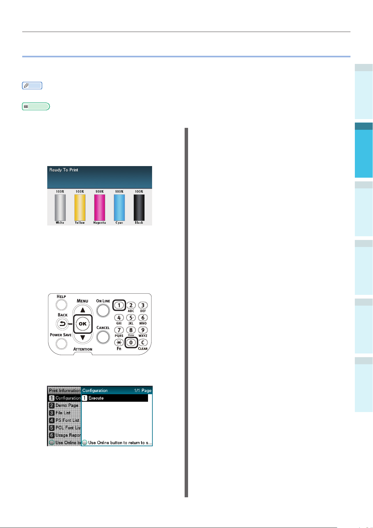
Test Printing Using the Printer Only
Test Printing Using the Printer Only
Check that printing is actually enabled using the printer only. Check by printing the device setup and
setup details, which enable the status to be checked. (Printer information.)
Memo
Print the "printer information" on A4 size paper. Set A4 size paper in the paper feed tray.
Reference
See “Turning ON the Power Supply” (P.51) for how to turn ON the power supply.
Set A4 paper in tray 1.
1
Check that the standby screen is
2
displayed in the liquid crystal panel.
Press the [Fn] key.
3
The numerical values input screen will
be displayed.
1
Before use
2
Setting Up
3
4
Basic Device Operations
Press [1], [0], [0], and then press the
4
[OK] button.
When [Execute] has been selected,
5
press the [OK] button.
The printer information will be
displayed.
AppendixPrinting
Index
- 53 -
Page 54
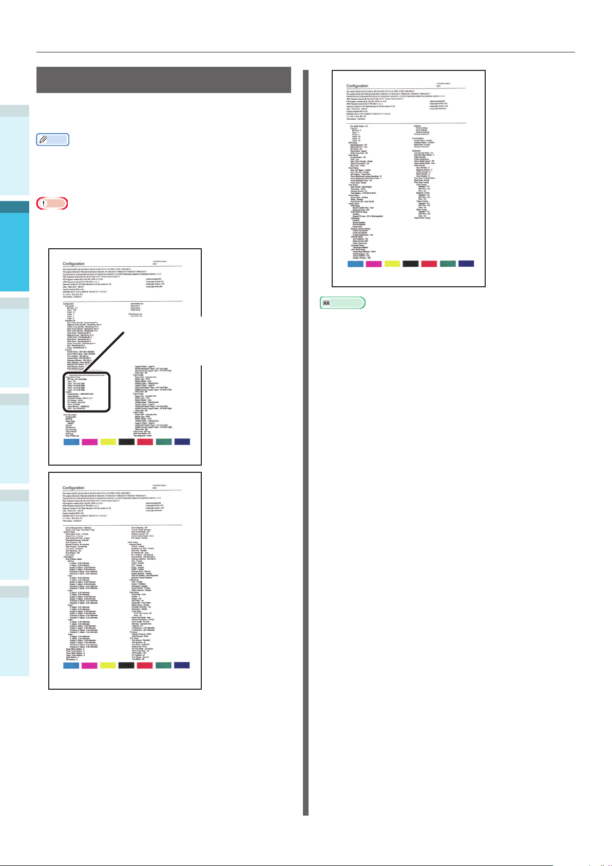
Test Printing Using the Printer Only
Printer Information
During test printing, the following device setup
1
details (printer information) will be printed.
Before use
Memo
Use the printer information to check the functions that
are currently usable, the settings table, the software and
hardware versions built into the device, and the print
quantity, etc.
2
Setting Up
Note
The printer information described here is a sample. The
printer information printed by your device may differ in
places.
3
Check here if an option
(expansion tray unit or
built-in HDD) is
mounted.
4
Basic Device Operations
Reference
You can also print function reports and demo pages, etc.
For details, see "Advanced".
AppendixPrinting
Index
- 54 -
Page 55

Connecting the PC
Connecting the PC
This section explains how to connect the device to a PC, and how to install the printer drivers from the
enclosed "Software DVD-ROM". Prepare a PC connected to a DVD drive.
Flow for Installing Drivers on a PC
Connecting to PC
For Windows For Macintosh
Connecting via a
network
Setting the IP address
in the device
Connecting via USB
Turning ON the device power supply
Enabling the device
Connecting via a network
Connecting via
EtherTalk
EtherTalk
Connecting via
Bonjour/Rendezvous
Connecting the cables
Connecting via USB
1
Before use
2
Setting Up
3
4
Basic Device Operations
Connecting the cables
Setting the IP
address, etc., in the
PC
Disabling device sleep
mode
Turning ON the PC power supply
AppendixPrinting
Setting EtherTalk in
the PC
Installing the printer drivers
Index
Adding devices to the PC
Checking operations from the PC
(See “3.Printing”)
- 55 -
Page 56

Connecting the PC
Operating Environment
The device is compatible with the following operating systems (OS).
1
Before use
Windows 10/Windows 10 (64-bit version)*
Windows 8.1/Windows 8.1 (64-bit version)*
Windows 8/Windows 8 (64-bit version)*
Windows Server 2016
2
Setting Up
Windows Server 2012 R2
Windows Server 2012
Windows 7/Windows 7 (64-bit version)
Windows Server 2008 R2
Windows Server 2008/Windows Server 2008 (x64 version)
Mac OS X 10.10.5 to OS X 10.13
3
*: Only desktop mode is compatible for Windows 10, 8.1 and Windows 8.
Printer Driver Types
The following types of printer driver can be installed.
Windows
4
Basic Device Operations
PS Applies to the printing of documents including PostScript fonts and EPS data.
Mac OS X
PS Applies to the printing of documents including PostScript fonts and EPS data.
AppendixPrinting
Note
Descriptions may differ depending on the printer driver, and Windows or Mac OS version.
Type Explanation
Can also be used for regular printing.
Type Explanation
Can also be used for regular printing.
Index
- 56 -
Page 57
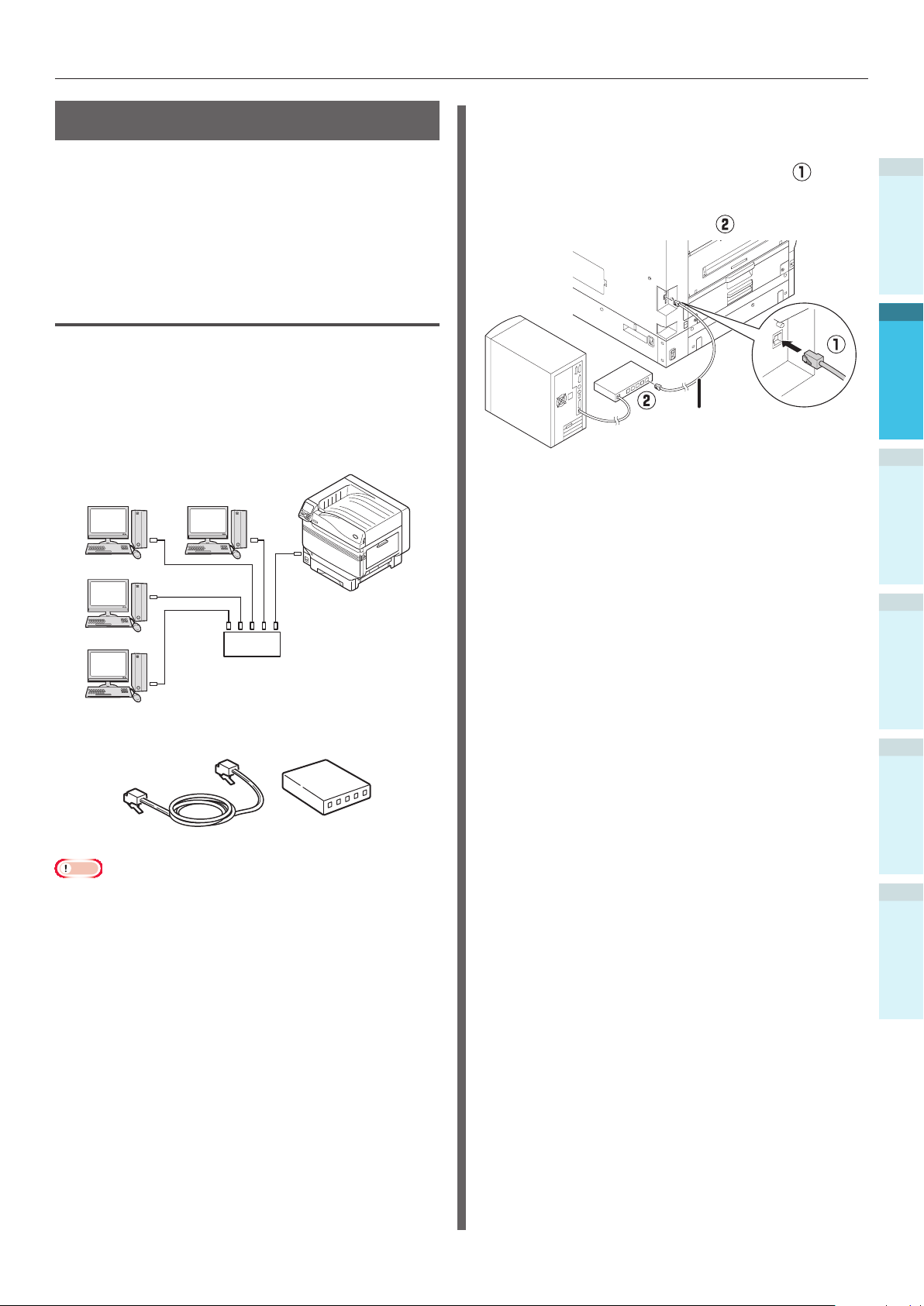
Connecting the PC
Connecting Cables
Connect the device to a PC or network.
The device is equipped with the LAN (network)
interface connectors and USB interface
connectors as standard. Connections can be
made to the network directly using LAN cables,
and to the PC using USB cables.
Connecting Using LAN Cables
Connecting the device to a network such as
LAN (Ethernet*), etc., enables the device to
be shared by all the PCs on the network. This
system can be used by OS such as Windows or
Mac, etc.
*: The device is equipped with network interfaces compatible
with 10BASE-T/100BASE -TX/1000BASE-T as standard.
Windows
Macintosh
Connecting LAN Cables
Connect the LAN cable to the LAN
1
(network) interface connector (
Connect the other end of the LAN cable
to the hub connector (
LAN cable
).
LAN (network)
Connector
).
interface
1
Before use
2
Setting Up
3
Windows
Macintosh
Hub
Preparations
LAN cable
Note
LAN cables and hubs are not enclosed with the device.
Prepare LAN cables (category 5 or greater, twist pair
cable, straight) and hubs as necessary.
The setup must be changes if using with 1000BASE-T
as the factory default settings are "Gigabit network:
Disabled" in the administrator setup menu.
Setup method: In the control panel, select [Admin
Setup]> Enter the password> [Network Setup]> [Gigabit
network]> [Enable].
Hub
4
Basic Device Operations
AppendixPrinting
Index
- 57 -
Page 58

Connecting the PC
Connecting Using USB Cables
Connect the device and PC using USB cables.
1
Before use
USB cable
2
Setting Up
3
4
Basic Device Operations
Preparations
USB cable
Note
USB cables are not enclosed with the device. Prepare USB
cables with USB2.0 specications, length 2m max. as
necessary.
If connecting using USB2.0 Hi-Speed mode, use a USB
cable with Hi-Speed USB2.0 specications.
Connecting USB Cables
Note
If the printer drivers are not installed on the PC, remove
the USB cable fromthe PC, and rst install the printer
drivers. (page 64)
Pay attention to the connector
1
orientation, and connect the square end
of the USB cable to the Printer (
Connect the other, at end to the PC (
USB port
USB interface
connector
USB cable
Note
Be careful not to insert the USB cable into the LAN
(network) interface connector. Doing so may cause a
printer malfunction.
Do not insert the USB cable when the PC or device power
supply is ON. Doing so may cause a printer malfunction.
).
).
AppendixPrinting
Index
Memo
Set the device USB baud rate using the control panel
according to the USB port baud rate (speed) mounted
to the PC. For the control panel, see “Control Panel
Appearance” (P.25).
- 58 -
Page 59

Connecting the PC
Installer Printer Drivers
(Windows)
Network Connections
To connect the Windows PC and device to the
network, rst set the device IP address. Next,
install the printer drivers on the PC.
If there are no DHCP or BOOTP servers on the
network, it is necessary to set the IP address on
the PC and device manually.
Further, it is also necessary to set the IP address
in the PC and device manually if instructed to
set a specic IP address determined by the in-
house network administrator, provider, or router
manufacturer.
Setup Flow
Turning ON the device power supply
Setting the IP address in the device
Turning ON the PC power supply
Setting the IP Address in the
Device Using the Control Panel
Memo
If conguring using a small scale network that connects
the device to a single PC, set the following IP address
(conforming to RFC1918).
PC
- IP address: Any from 192.168.0.1 to 254
- Subnet mask: 255.255.255.0
- Default gateway: Not used
- DNS server: Not used
Device
- IP address setup: Manual from 192.168.0.1 to 254
(Select a different value fom the PC.)
- Subnet mask: 255.255.255.0
- Default gateway: 0.0.0.0
- Network size: Small scale
This section explains the following settings as an
example.
IP address: 192.168.0.3 (PC)
192.168.0.2 (Device)
Subnet mask: 255.255.255.0
Gateway address: 192.168.0.1
Press either the scroll button or
1
on the control panel to display the
"Functions" screen.
1
Before use
2
Setting Up
3
4
Basic Device Operations
Setting the IP address, etc., in the PC
Installing the printer drivers
Note
If the IP address is incorrect, the network may go
down, or internet connections be disabled. Check the IP
addresses that can be set in the device with your in-house
network administrator or internet service provider.
The server on the network (DHCP, etc.) depends on the
network environment in use. Check with your in-house
network administrator, internet service provider, or router
manufacturer.
Setup requires computer administrator privileges.
In "Setting Up", the operating procedure described is for
Windows 7 unless otherwise specied. The screens and
operating procedure may differ depending on the OS.
Press the scroll button several times
2
to select [Admin Setup], and then press
the [OK] button.
AppendixPrinting
Index
- 59 -
Page 60

Connecting the PC
Use Online button to return to standby sc
Use Online button to return
3
1
Before use
2
Setting Up
4
3
5
4
Basic Device Operations
6
AppendixPrinting
Index
Use the 10-key pad to enter the
administrator password.
The default factory-set password is
"aaaaaa". Press the [OK] button after
entering each individual character.
Press the [OK] button.
Check that [Network Setup] has been
selected, and press the [OK] button.
Admin Setup 1/2 Page
Network Setup
USB Setup
Print Setup
PS Setup
PCL Setup
XPS Setup
Use Online button to return to standby screen
Press the scroll button several times
to select [IP Address Set], and then
press the [OK] button.
Network Setup 1/2 Page
TCP/IP
NetBIOS over TCP
EtherTalk
IP Address Set
IPv4 Address
Subnet Mask
Use Online button to return to standby screen
If setting the IP address manually, press
7
the scroll button
to select [Manual],
and then press the [OK] button.
Go to Step 8
Network Setup
TCP/IP
NetBIOS over TCP
EtherTalk
IP Address Set
IPv4 Address
Subnet Mask
Use Online button to return to standby scr
Auto
Manual
Use Online button to return
1/1 PageIP Address Set
If acquiring the IP address automatically,
check that [Auto] has been selected, and
then press the [OK] button.
Go to Step 14
Network Setup
TCP/IP
NetBIOS over TCP
EtherTalk
IP Address Set
IPv4 Address
Subnet Mask
Use Online button to return to standby scr
Auto
Manual
Use Online button to return
1/1 PageIP Address Set
Press the scroll button several times
8
to select [IPv4 Address], and then click
the [OK] button.
Network Setup 1/2 Page
TCP/IP
NetBIOS over TCP
EtherTalk
IP Address Set
IPv4 Address
Subnet Mask
Use Online button to return to standby screen
Use either the scroll buttons or the
9
10-key pad to enter the rst 3 digits
of the IP address, and then press the
[OK] button. Enter the next 3 digits
in the same way. When all entries are
complete, press the [BACK] button.
- 60 -
To move to the next box, press the [OK]
button.
Network Setup
TCP/IP
NetBIOS over TCP
EtherTalk
IP Address Set
IPv4 Address
Subnet Mask
IPv4 Address
xxx.xxx.xxx.xxx
Page 61

Connecting the PC
Press the scroll button to select
10
[Subnet Mask], and then press the [OK]
button.
Network Setup 1/2 Page
TCP/IP
NetBIOS over TCP
EtherTalk
IP Address Set
IPv4 Address
Subnet Mask
Use Online button to return to standby screen
Enter the subnet mask in the same way
11
as the IP address. When all entries are
complete, press the [BACK] button.
Network Setup
Subnet Mask
Use Online button to return to standby screen
Subnet Mask
xxx.xxx.xxx.xxx
Use Online button to return
Press the [ON LINE] button to complete
14
the network setup.
1
Before use
2
Setting Up
3
Press the scroll button to select
12
[Gateway Address], and then press the
[OK] button.
Network Setup 2/2 Page
Gateway Address
Use Online button to return to standby screen
Enter the gateway address in the same
13
way as the IP address. When all entries
are complete, press the [BACK] button.
Network Setup
Gateway Address
Use Online button to return to standby screen
Gateway Address
xxx.xxx.xxx.xxx
Use Online button to return
4
Basic Device Operations
AppendixPrinting
Index
- 61 -
Page 62

Connecting the PC
Setting the IP Address in the PC
Note
If the IP address has already been set in the PC or is
1
Before use
2
Setting Up
acquired automatically, go to “Setting the IP Address in
the Device Using the Control Panel” (P.59).
Turn ON the PC power supply to start
1
Windows.
Click [Start], and select [Windows
2
System] > [Control panel].
Click [View network status and tasks].
3
3
Select [Internet Protocol Version 4 (TCP/
5
IPv4)], and click [Properties].
Enter the IP address, Subnet mask,
6
Default gateway, and DNS server, and
click [OK].
4
Basic Device Operations
AppendixPrinting
Index
Click [Ethernet], and then click
4
[Properties] in the "Ethernet" window.
Memo
If acquiring the IP address from the DHCP server
automatically, select "Obtain an IP address
automatically", and do not enter an IP address.
Do not enter if not using a Default gateway or DNS
server.
Close the "Local Area Connection
7
Properties" window.
- 62 -
Page 63

Connecting the PC
Installing Printer Drivers
Check that the device and PC are
1
connected, and that the power supply is
turned ON.
Reference
“Connecting Using LAN Cables” (P.57)
z
Insert the included “Software DVD-
2
ROM” into a computer.
When [Auto Play] is displayed, click [Run
3
setup.exe].
Select the model name of the machine,
8
and then click [Next].
Click [Install Optional Software].
9
1
Before use
2
Setting Up
3
Memo
If the [User Account Control] dialog is displayed,
z
click [Yes].
Select a language from the drop-down
4
list.
Read the license agreement, and then
5
click [Accept].
Read [Environment advice], and then
6
click [Next].
Select [Network] or [USB connection]
7
in accordance to the connection method
of the machine and computer, and then
click [Next].
Installation starts.
Memo
The following software is installed.
z
PS Printer Driver (Including Network Extension
z
and PS Gamma Adjuster)
Install other software from Custom Install.
z
Make sure that the software is
10
successfully installed, and then click
[Printing Test].
Select the printer for test printing, and
the click [Printing Test].
Make sure that the test printing was
successful, and then click [OK].
4
Basic Device Operations
AppendixPrinting
Index
If the [Windows Security Alert] dialog is
displayed, click [Allow access].
- 63 -
Page 64

Connecting the PC
11
1
Before use
2
Setting Up
12
3
4
Basic Device Operations
Click [Complete].
Click [Next].
USB Connections
Note
Check that the device power supply is turned OFF.
z
Setup requires computer administrator privileges.
z
This section described the operating procedure for
z
Windows 7 unless otherwise specied. The screens and
operating procedure may differ depending on the OS.
Setup Flow
Turning ON the device power supply
Turning ON the PC power supply
Installing the printer drivers
Turn ON the PC power supply to start
1
Windows.
Memo
zWhen the device power supply is turned ON, the "Add
new software wizard" may be displayed in the screen.
If this happens, click "CANCEL", and then turn OFF
the device beore proceeding to the next step.
AppendixPrinting
Index
If the following dialog is displayed, click
[Yes].
Click [Exit].
13
Insert the included “Software DVD-
2
ROM” into a computer.
When [Auto Play] is displayed, click [Run
3
setup.exe].
Memo
If the [User Account Control] dialog is displayed,
z
click [Yes].
Reference
For how to print from the PC, see “Printing from Trays”
z
(P.81).
- 64 -
Select a language from the drop-down
4
list.
Read the license agreement, and then
5
click [Accept].
Page 65
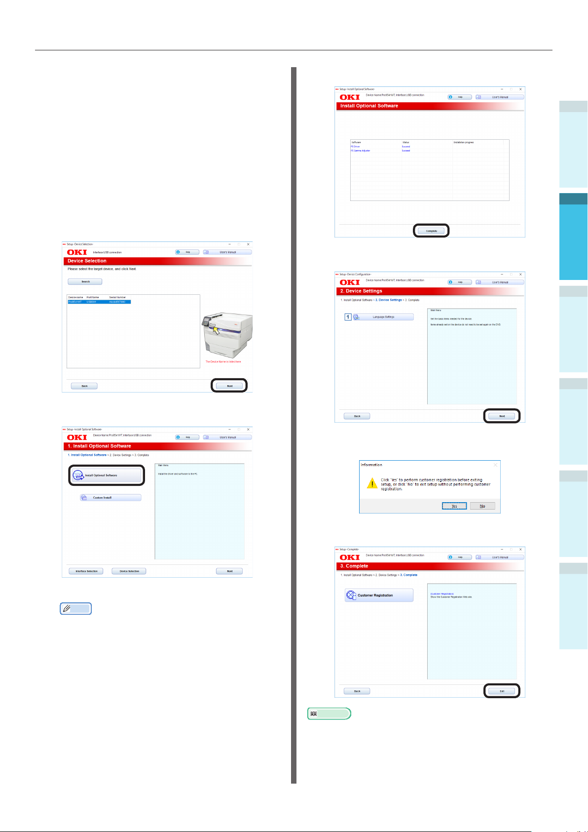
Connecting the PC
Read [Environment advice], and then
6
click [Next].
Select [Network] or [USB connection]
7
in accordance to the connection method
of the machine and computer, and then
click [Next].
If the [Windows Security Alert] dialog is
displayed, click [Allow access].
Select the model name of the machine,
8
and then click [Next].
Click [Complete].
11
1
Before use
2
Setting Up
Click [Next].
12
3
Click [Install Optional Software].
9
Installation starts.
Memo
The following software is installed.
PS Printer Driver (Including Network Extension
and PS Gamma Adjuster)
Install other software from Custom Install.
If the following dialog is displayed, click
[Yes].
Click [Exit].
13
4
Basic Device Operations
AppendixPrinting
Index
Make sure that the software is
10
successfully installed, and then click
[Printing Test].
Select the printer for test printing, and
the click [Printing Test].
Make sure that the test printing was
successful, and then click [OK].
Reference
For how to print from the PC, see “Printing from Trays”
(P.81).
- 65 -
Page 66

Connecting the PC
Installing Printer Drivers
(Macintosh)
1
Before use
Network Connections
To connect Mac OS X and the device via a
network, install the printer drivers on the
computer, and then set the device as a network
printer.
2
Setting Up
3
4
Basic Device Operations
Deciding the Print Method
(Protocol)
There are two printing methods from Mac OS X:
Using EtherTalk, and using Bonjour/Rendezvous.
Print method
(Protocol)
EtherTalk Uses functions mounted
Bonjour
Rendezvous
Features
as standard to OS X
10.3 to 10.5.
Use this with TCP/IP
networks.
Setup Flow
The setup procedure may differ depending on
the print method.
EtherTalk
Turning ON the power
supply
Enabling the device
EtherTalk
Disabling device sleep
mode
Turning ON the PC power
supply
Setting EtherTalk in the
PC
Turning ON the power
supply
Turning ON the PC power
supply
Bonjour/
Rendezvous
AppendixPrinting
Index
Installing the printer
drivers
Adding devices to the PC Adding devices to the PC
Go to “Using EtherTalk”. Go to “Using Bonjour
Note
Upgrading the Mac OS X or printer driver version may
result in differences from the description in the manual.
Disable all anti-virus software before starting the setup.
Installing the printer
drivers
(Rendezvous)” (P.70).
- 66 -
Page 67

Connecting the PC
Using EtherTalk
Enable EtherTalk using the control panel,
and disable sleep mode
If connecting to a network using EtherTalk, it
is necessary to enable EtherTalk in the printer,
and disable sleep mode. Next, install the printer
drivers in the computer.
Reference
People using Bonjour go to “Using Bonjour (Rendezvous)”
(P.70).
Press either the scroll button or
1
on the control panel to display the
"Functions" screen.
Check that [Network Setup] has been
5
selected, and press the [OK] button.
Admin Setup 1/2 Page
Network Setup
USB Setup
Print Setup
PS Setup
PCL Setup
XPS Setup
Use Online button to return to standby screen
Press the scroll button several times
6
to select [EtherTalk], and then click the
[OK] button.
Network Setup 1/1 Page
TCP/IP
NetBIOS over TCP
EtherTalk
IP Address Set
IPv4 Address
Subnet Mask
Use Online button to return to standby screen
1
Before use
2
Setting Up
3
Press the scroll button several times
2
to select [Admin Setup], and then press
the [OK] button.
Use the 10-key pad to enter the
3
administrator password.
The default factory-set password is
"aaaaaa". Press the [OK] button after
entering each individual character.
Press the scroll button to select
7
[Enable], and then press the [OK]
button.
Network Setup
TCP/IP
NetBIOS over TCP
EtherTalk
IP Address Set
IPv4 Address
Subnet Mask
Use Online button to return to standby screen
Enable
Disable
Use Online button to return
1/1 PageEtherTalk
Press the [BACK] button to display the
8
"Network Setup" screen.
Network Setup 1/2 Page
TCP/IP
NetBIOS over TCP
EtherTalk
IP Address Set
IPv4 Address
Subnet Mask
Use Online button to return to standby screen
4
Basic Device Operations
AppendixPrinting
Index
Press the [OK] button.
4
- 67 -
Page 68

Connecting the PC
9
1
Before use
2
Setting Up
10
3
Press the [BACK] button to display the
[Admin Setup] screen.
Admin Setup 1/2 Page
Network Setup
USB Setup
Print Setup
PS Setup
PCL Setup
XPS Setup
Use Online button to return to standby screen
Press the scroll button several times
to select [Power Setup], and then click
the [OK] button.
Press the [ON LINE] button to return to
13
the standby screen.
4
Basic Device Operations
AppendixPrinting
Index
Press the scroll button to select
11
[Sleep], and then click the [OK] button.
Press the scroll button to select
12
[Disable], and then click the [OK]
button.
- 68 -
Page 69
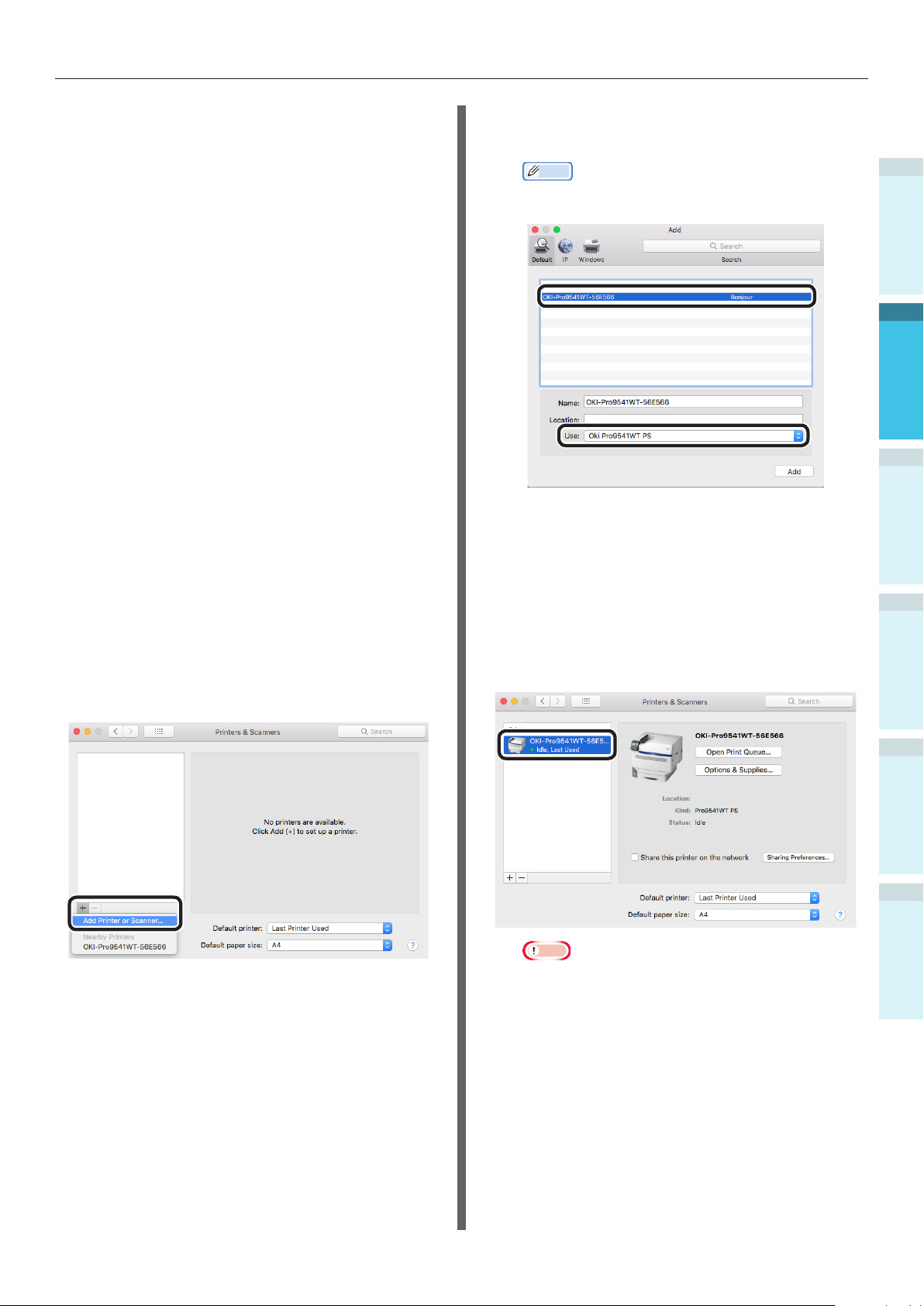
Connecting the PC
Installing the printer drivers on the computer
Make sure that the machine and a
1
computer are connected and the
machine is turned on.
Insert the “Software DVD-ROM” into a
2
computer.
Double-click the [OKI] icon on the
3
desktop.
[Drivers] > [PS] > Double-click
4
[Installer for OSX].
Enter the administrator password, and
5
then click [OK].
Follow the on-screen instructions to
complete the installation.
Select [System Preferences] from the
6
Apple menu.
Click [Printers & Scanners].
7
Click [+].
8
Select [Add Printer or Scanner...] when
the menu is displayed.
Select the machine, and then select [Oki
10
Pro9541WT PS] in [Use].
Memo
To change the name, enter a new name into
[Name:].
Click [Add].
11
If the conrmation screen for optional
12
equipment appears, click [OK].
Make sure that the machine is added
13
to [Printers] and [Pro9541WT PS] is
displayed for [Kind].
1
Before use
2
Setting Up
3
4
Basic Device Operations
Click [Default].
9
Note
If [Pro9541WT PS] is not displayed for [Kind]
correctly, click [-], delete the machine from
[Printers], and then newly perform steps 8 to 12.
Click [Open Print Queue...].
14
Select [Print Test Page] from the
15
[Printer] menu.
AppendixPrinting
Index
- 69 -
Page 70

Connecting the PC
1
Before use
1
2
2
Setting Up
3
4
3
5
4
Basic Device Operations
6
7
8
AppendixPrinting
Using Bonjour (Rendezvous)
Installing the printer drivers on the
computer
Make sure that the machine and a
computer are connected and the
machine is turned on.
Insert the “Software DVD-ROM” into a
computer.
Double-click the [OKI] icon on the
desktop.
[Drivers] > [PS] > Double-click
[Installer for OSX].
Enter the administrator password, and
then click [OK].
Follow the on-screen instructions to
complete the installation.
Select [System Preferences] from the
Apple menu.
Click [Printers & Scanners].
Click [+].
Select [Add Printer or Scanner...] when
the menu is displayed.
Select the machine, and then select [Oki
10
Pro9541WT PS] in [Use].
Memo
To change the name, enter a new name into
[Name:].
Click [Add].
11
If the conrmation screen for optional
12
equipment appears, click [OK].
Make sure that the machine is added
13
to [Printers] and [Pro9541WT PS] is
displayed for [Kind].
Index
Click [Default].
9
- 70 -
Note
If [Pro9541WT PS] is not displayed for [Kind]
correctly, click [-], delete the machine from
[Printers], and then newly perform steps 8 to 12.
Click [Open Print Queue...].
14
Select [Print Test Page] from the
15
[Printer] menu.
Page 71

Connecting the PC
USB Connections
Make sure that the machine and a
1
computer are connected and the
machine is turned on.
Insert the “Software DVD-ROM” into a
2
computer.
Double-click the [OKI] icon on the
3
desktop.
[Drivers] > [PS] > Double-click
4
[Installer for OSX].
Enter the administrator password, and
5
then click [OK].
Follow the on-screen instructions to
complete the installation.
Select [System Preferences] from the
6
Apple menu.
Click [Printers & Scanners].
7
Click [+].
8
Select [Add Printer or Scanner...] when
the menu is displayed.
Select the machine, and then select
10
[OKI DATA CORP Pro9541WT] in [Use].
Memo
To change the name, enter a new name into
[Name:].
Click [Add].
11
If the conrmation screen for optional
12
equipment appears, click [OK].
Make sure that the machine is added
13
to [Printers] and [Pro9541WT PS] is
displayed for [Kind].
1
Before use
2
Setting Up
3
4
Basic Device Operations
Click [Default].
9
Note
If [Pro9541WT PS] is not displayed for [Kind]
correctly, click [-], delete the machine from
[Printers], and then newly perform steps 8 to 12.
Click [Open Print Queue...].
14
Select [Print Test Page] from the
15
[Printer] menu.
AppendixPrinting
Index
- 71 -
Page 72
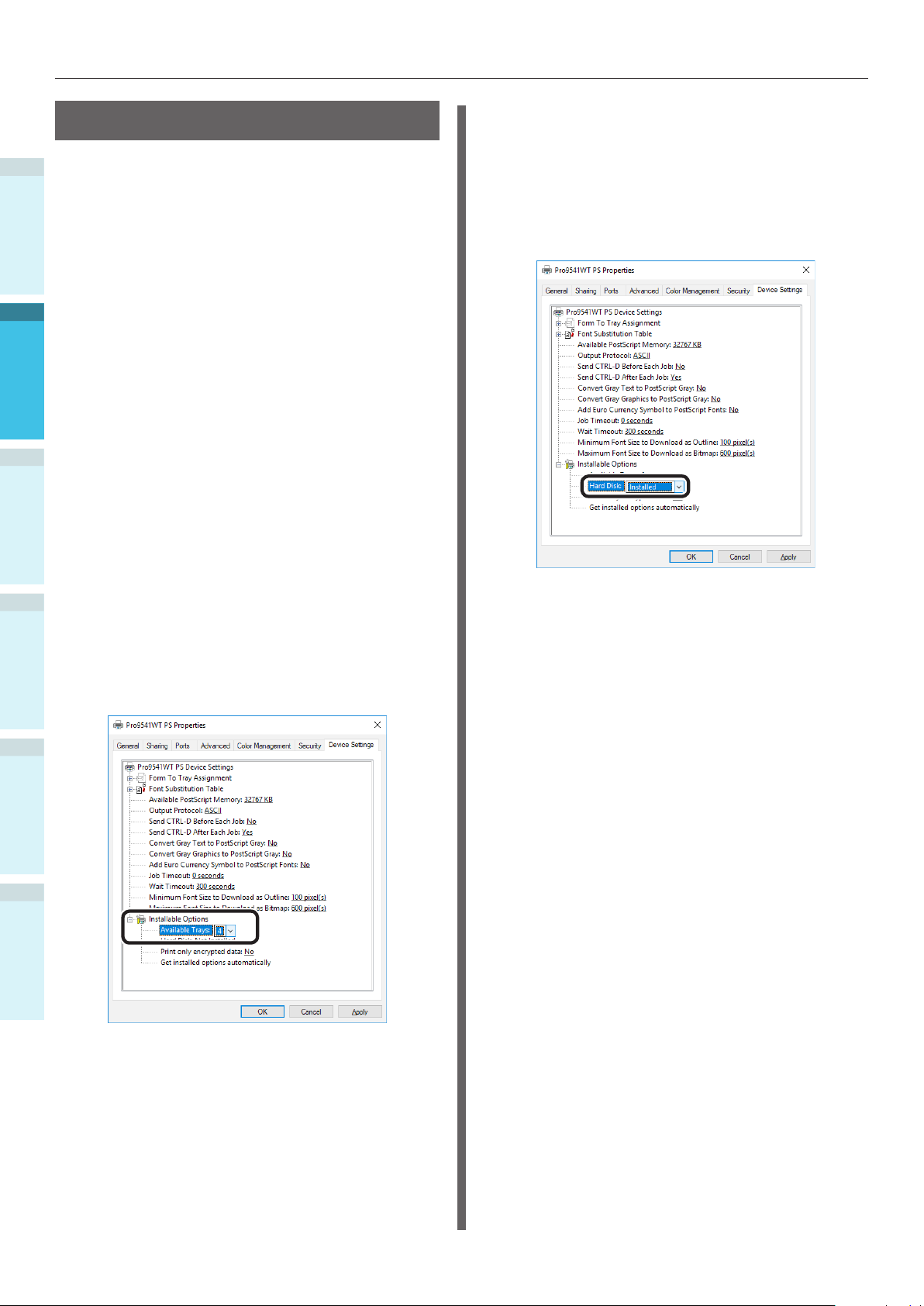
Connecting the PC
Adding Options
Use the following procedure to set the printer
1
drivers if an optional expansion unit or built-in
HDD have been mounted to the device.
Before use
Windows PS Printer Driver
Click [Start], and select [Devices and
1
2
Setting Up
Printers].
Right-click the Pro9541WT icon, and
2
select [Printer properties].
Select the [Device Settings] tab.
3
3
Adding an Expansion Tray Unit
If using a network connection, click
4
[Get installed options automatically] in
[Installable Options].
Adding the Built-in HDD
If using a network connection, click
4
[Get installed options automatically] in
[Installable Options].
If using a USB connection, select
[Installed] in [Hard Disk].
4
Basic Device Operations
AppendixPrinting
Index
If using a USB connection, enter the
number of trays minus the multipurpose tray in [Available Trays].
For example, if three expansion trays
are mounted, the usable trays are trays
1/2/3/4, so enter "4".
Click [OK].
5
- 72 -
Page 73
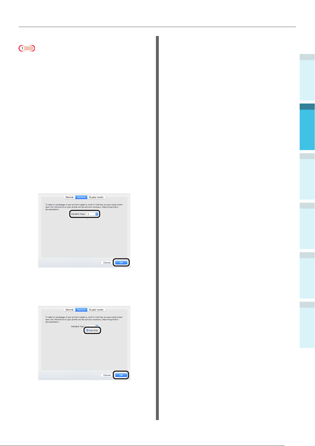
Mac OS X PS Printer Driver
Note
This section describes the operations procedures for
Mac OS X 10.8 unless otherwise specied. Screens and
operations procedures may differ depending on the
version.
Select [System Preferences] from the
1
Apple menu.
Connecting the PC
1
Before use
Click [Print & Scan].
2
Select the printer, and click [Options
3
and Supplies].
Select the [Driver] tab.
4
Adding an Expansion Tray Unit
Select the correct value for [Available
5
Trays], and click [OK].
2
Setting Up
3
4
Basic Device Operations
Adding the Built-in HDD
Enable the [Hard Disk] check box, and
5
click [OK].
Click [OK].
6
AppendixPrinting
Index
- 73 -
Page 74

Connecting the PC
Memo
1
Before use
2
Setting Up
3
4
Basic Device Operations
AppendixPrinting
Index
- 74 -
Page 75

3. Printing
This chapter explains the methods from setting the paper in the device to actual printing.
Paper
Paper
1
Before Use
Usable Paper Types
For high-quality printing it is necessary to use paper that satises conditions regarding quality,
thickness, paper nish, etc. If printing on paper not recommended by OKI, thoroughly test the print
quality and paper traveling performance, etc., and check that there are no impediments before use.
If using a (paper) medium that is curled or wrinkled before printing, print quality and paper traveling
performance cannot be assured.
2
3
Printing
4
Basic Device Operations
AppendixSetting Up
Index
- 75 -
Page 76

Paper
Paper Types, Size, and Thickness
Note
Paper sources and output are restricted by paper type, size, and thickness.
1
Before Use
2
Type Size unit: mm (inches) Thickness
Plain paper A3Nobi 328×453
A3Wide 320×450
A3 297×420
A4 Wide 225×320
A4 210×297
Note
If the paper size settings satisfy the
following conditions, print speed will be
slowed.
Paper size: A6, A5; paper width 216mm
(letter width) max.
A5 148×210
A6 105×148
B4 257×364
B5 182×257
B6 128×182
3
Letter 215.9×279.4 (8.5×11)
Legal (13 inch) 215.9×330.2 (8.5×13)
Printing
Legal (13.5 inch) 215.9×342.9 (8.5×13.5)
Legal (14 inch) 215.9×355.6 (8.5×14)
Executive 184.2×266.7 (7.25×10.5)
Tabloid Extra 304.8×457.2 (12×18)
Tabloid 279.4×431.8 (11×17)
4
Basic Device Operations
Statement 139.7×215.9 (5.5×8.5)
13×18 inch 330.2×457.2
16K (184×260mm) 184×260
16K (195×270mm) 195×270
16K (197×273mm) 197×273
8K (260×368mm) 260×368
8K (270×390mm) 270×390
8K (273×394mm) 273×394
AppendixSetting Up
Partially
printed paper
Custom Width 64 to 330
Length 89 to 1321
GSM paper weight 52-360g/m
weight 45-309kg)
Equivalent to plain paper. GSM paper weight 52-360g/m
weight 45-309kg)
Color paper Equivalent to plain paper. GSM paper weight 52-360g/m
weight 45-309kg)
Transparency A4 0.1 to 0.125mm
Index
Letter
2
(ream
2
(ream
2
(ream
- 76 -
Page 77

Setting the Paper Weight
Set the paper weight according to the ream weight of the paper to be used.
This step is not required for Media Weight (Auto), but in case of paper jam or decrease in printing
quality, manual setting is recommended.
Media Weight Ream weight
Ultra Light 14lb Media Weight < 17lb
Light 17lb
Medium Light 18lb < Media Weight
Medium 22lb < Media Weight < 28lb
Medium Heavy 28lb
Heavy 32lb < Media Weight
Ultra Heavy1 34lb < Media Weight
Ultra Heavy2 50lb < Media Weight
Ultra Heavy3 57lb < Media Weight
Ultra Heavy4 68lb < Media Weight
Ultra Heavy5 85lb < Media Weight
52g/m
2
Media Weight < 64g/m
2
45kg Media Weight < 55kg
Media Weight 18lb
64g/m2 Media Weight 68g/m
2
55kg Media Weight 59kg
22lb
68g/m2 < Media Weight 83g/m
2
59kg < Media Weight 71kg
2
83g/m
< Media Weight < 105g/m
71kg < Media Weight < 90kg
Media Weight 32lb
105g/m2 Media Weight 120g/m
90kg Media Weight 103kg
34lb
120g/m2 < Media Weight 128g/m
103kg < Media Weight 110kg
50lb
128g/m2 < Media Weight 188g/m
110kg < Media Weight 162kg
57lb
188g/m2 < Media Weight 216g/m
162kg < Media Weight 186kg
68lb
216g/m2 < Media Weight 256g/m
186kg < Media Weight 220kg
85lb
256g/m2 < Media Weight 320g/m
220kg < Media Weight 275kg
96lb
320g/m2 < Media Weight 360g/m
275kg < Media Weight 310kg
2
2
2
2
2
2
2
2
Paper
1
Before Use
2
3
Printing
4
Basic Device Operations
AppendixSetting Up
*: Manual paper weight setting is recommended when using media of Ultra Light or Ultra Heavy5.
- 77 -
Index
Page 78

Paper
Paper Feed and Output Methods Selectable for Each
Paper type
1
Before Use
2
3
Printing
4
Basic Device Operations
AppendixSetting Up
O: Usable
X: Not usable
Settable tray Output bin
Type Size Thickness
Plain paper
Transparency*2A4, Letter - O O X O X
*1: Use the printer control panel to set the paper size of the tray used to [Custom], and set [X Dimension] and [Y Dimension] to
the values shown in the table below. Use the printer drivers to select the values from the table below.
A3Nobi, A3Wide, A3,
A4, A5, A6, B4, B5,
B6, B6 Half, Letter,
Legal13, Legal13.5,
Legal14, Executive
Tabloid Extra,
Tabloid, Statement,
16K (184x260mm),
16K (195x270mm),
16K (197x273mm),
8K (260x368mm),
8K (270x390mm),
8K (273x394mm),
13"×18"
Custom
(Width 90 to 330mm,
length 147 to 457mm)
Custom (Width 64mm
min., less than 90mm;
length greater than
457mm to 1321mm
max.)
Custom
(Width 64 to 330mm,
length 89 to 1321mm)
*1
GSM 52 to 320 g/m
GSM larger than 320
up to 360g/m2 max.
GSM 52 to 320 g/m
GSM 52 to 320 g/m
GSM larger than 320
up to 360g/m
2
max.
Multi-purpose
tray
2
O O O O O
O X X O X
2
O O O O O
2
O X X O X
O X X O X
Tray 1
Trays
2 to 5
(Optional)
Face-up
Face-down
Paper Size
13"×18" 330 457 13×18in
*2: Print speed is slower for transparencies.
Index
Note
If setting paper in the tray horizontally ( ), print speed will be slower than if set vertically ( ).
Printing will be slower if the paper size set is A6 or A5 size, or has a smaller width than 216mm.
Paper width (mm) Paper length (mm)
Device Setup
- 78 -
Setting the printer
driver [Paper size]
Page 79

Paper
(Landscape) and
(Portrait) Icons
icon describes placing the paper vertically as
viewed from the front of the printer. (Paper is fed
horizontally.)
Paper Feed Orientation
Tra y s
icon describes placing the paper horizontally
as viewed from the front of the printer. (Paper is
fed vertically.)
1
Before Use
2
Setting Up
Paper Feed Orientation
Tra y s
3
Printing
Multi-Purpose Tray
Paper Feed
Orientation
Paper Feed
Orientation
Multi-Purpose Tray
Paper of the following sizes can be set either
horizontally or vertically.
The three types of A4, A5, B5, and Letter 16K,
and A4 wide
4
Basic Device Operations
Appendix
Index
- 79 -
Page 80
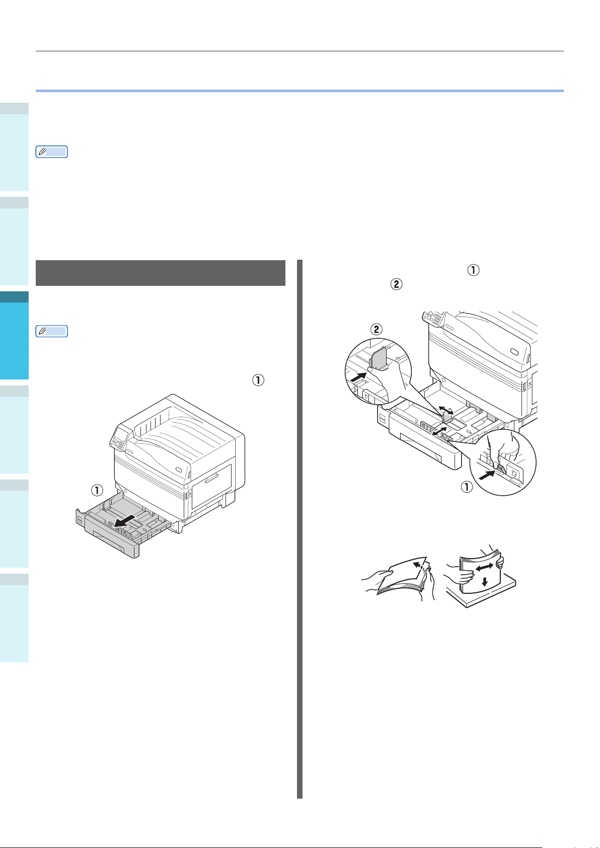
Printing from Trays
Printing from Trays
With the exception of some paper sizes, the printer automatically detects the size of paper set in trays
1
1 to 5*. Further, only the width of the paper size is automatically detected.
Before Use
*: Trays 2 to 5 are optional.
Memo
The printer does not automatically detect the following paper sizes.
- A3NOBI, tabloid extra, A3WIDE, 13×18"
- A5, A6
2
- legal13.5, legal14
- custom
If the printer does not detect automatically, use the control panel to set the paper size. For details, see “Setting Paper Using
the Control Panel” (P.84).
Set 13x18" as custom size.
Setting Paper in Trays 1 to 5
3
This section explains how to set paper in tray 1
or trays 2/3/4/5.
Printing
4
Basic Device Operations
AppendixSetting Up
Memo
In this section, setting paper in tray 1 is used as an
example. Set trays 2 to 5 using the same procedure.
Pull out the tray 1 paper cassette ( ).
1
Slide the paper guide ( ) and paper
2
stopper (
paper that has been set.
Thoroughly sort the paper. Carefully
3
align the ends of the paper horizontally.
) to align to the size of the
Index
- 80 -
Page 81

Printing from Trays
Set the paper with the print surface
4
face-down.
Note
Do not exceed the " " symbol ( ) on the paper
guide when setting the paper.
Printing from Trays
Open the le to be printed on the PC, and
select [Paper Size], [Paper Source], and [Media
Weight] to print via the paper driver.
This section explains how to print using "Tray 1"
or "Auto" from the following printer drivers.
Windows PS printer driver
Mac OS X printer driver (P.82)
Further, this explanation uses "WordPad" for
Windows as the application used. For Mac OS X,
the example uses "TextEdit".
Reference
For how to install the printer drivers, see “Connecting the
PC” (P.55).
For how to print from the multi-purpose tray, see “Printing
from the Multi-Purpose Tray” (P.84).
Memo
Select [Auto] in [Paper Source] to automatically select the
tray holding the designated paper.
1
Before Use
2
Setting Up
3
Printing
Memo
Set so there is no gap between the paper and the
paper guide or paper stopper.
Use the paper guide to secure the
5
paper.
Return the paper cassette to the tray.
6
Using Windows PS Printer Driver
Open the le to be printed using WordPad.
1
Click [Page Setup] in the [File] menu.
2
Select the paper size and print
3
orientation, and click [OK].
Click [Print] in the [File] menu.
4
Click [Advanced] (or [Preferences]).
5
Use [Paper Source] in the [Paper/
6
Quality] tab to select the tray to be
used, and click [Advanced].
4
Basic Device Operations
Appendix
Index
- 81 -
Page 82
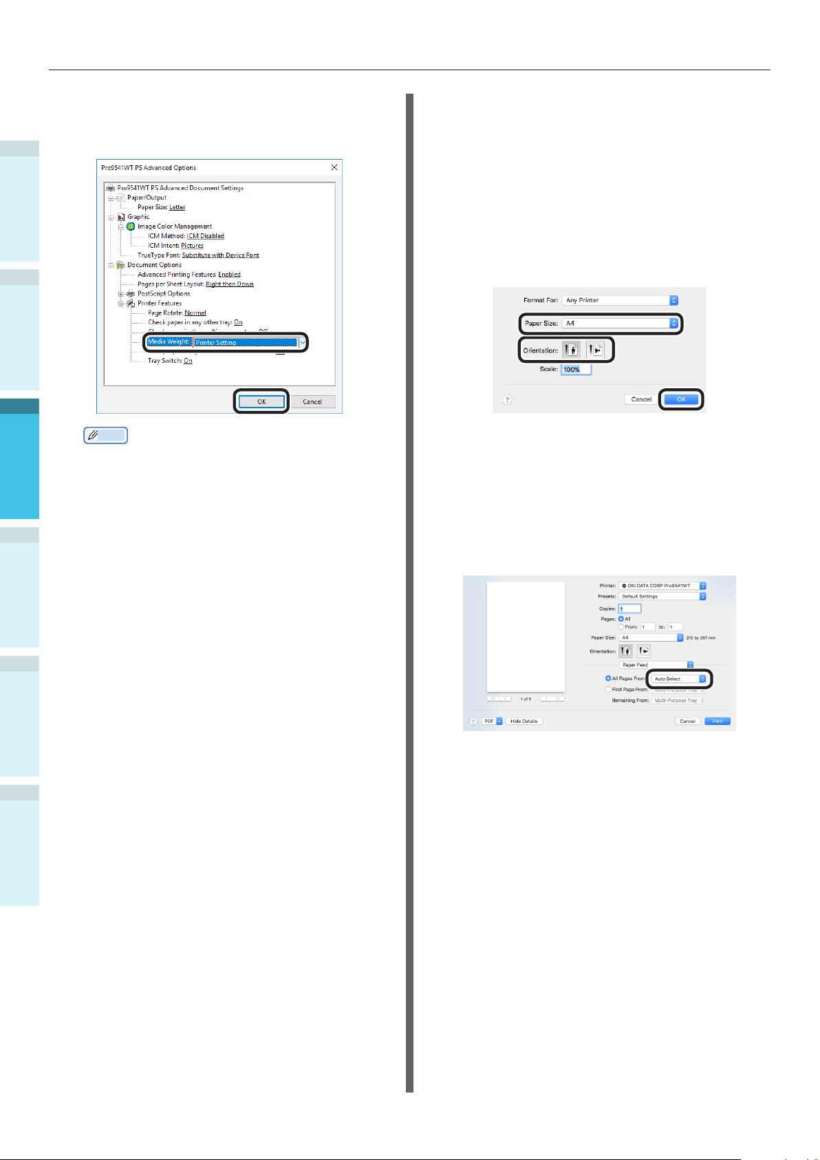
Printing from Trays
7
1
Before Use
2
3
Printing
4
Basic Device Operations
8
Select a suitable value from [Media
Weight] in the "Advanced Options"
screen, and then click [OK].
Memo
Normally, select [Printer Setting]. Select [Printer
Setting] to use the values set using the printer
control panel.
If outputting to the face-up stacker, open the printer
face-up stacker, and select [Stacker (Face-Up)] in
[Output Bin].
Click [OK] in the "Printing preferences"
screen.
Using Mac OS X Printer Driver
Open the le to be printed using
1
TextEdit.
Click [Page Setup] in the [File] menu.
2
Select the paper size and print
3
orientation using the page setup dialog
box, and click [OK].
Select [Print] in the [File] menu.
4
Select [Paper Feed] in the print dialog
5
box.
Check that [Auto Select] has been
6
selected.
9
AppendixSetting Up
Index
Click [Print] in the "Print" screen to
print.
Select [Print Options] using the print
7
dialog box.
- 82 -
Page 83

Chick the [Feed] tab in the printer
8
setup panel, and select [Media Type]
and [Media Weight].
Printing from Trays
1
Before Use
2
Setting Up
3
Memo
Normally, select [Printer Setting]. Select [Printer
Setting] to use the values set using the printer
control panel.
Click [Print] to print.
9
Printing
4
Basic Device Operations
Appendix
Index
- 83 -
Page 84
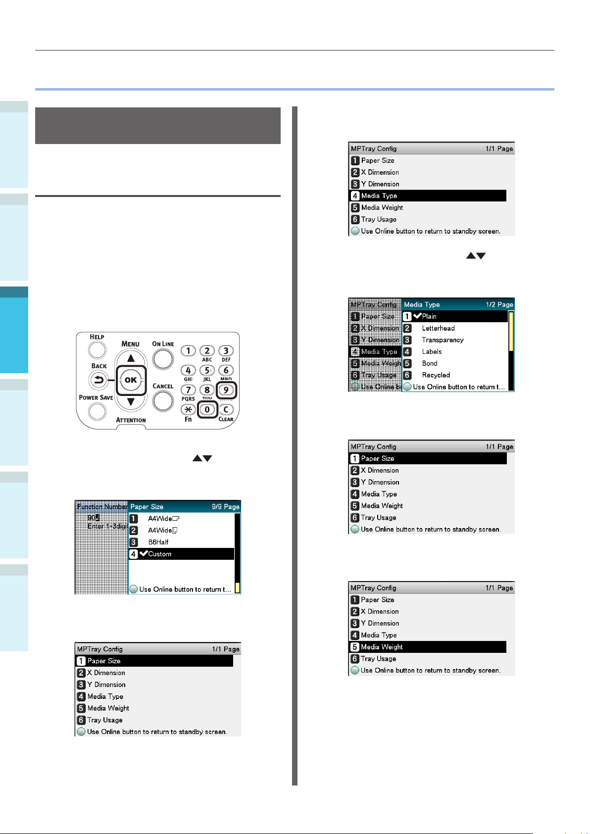
Printing from the Multi-Purpose Tray
Printing from the Multi-Purpose Tray
1
Setting Paper in the Multi-
Before Use
Purpose Tray
Setting Paper Using the Control
Panel
2
If the paper size is "Custom Size", use the
control panel to set the paper size.
Press the [Fn] key.
1
The numerical values input screen will
be displayed.
3
Press [9], [0], and click the [OK]
2
Printing
4
Basic Device Operations
button.
Select [Media Type], and press the [OK]
5
button.
Press the scroll buttons to select
6
the type of paper that has been set,
and click the [OK] button.
3
AppendixSetting Up
Index
4
Press the scroll buttons to select
the size of the paper that has been set,
and press the [OK] button.
Press the [BACK] button to return to
the previous screen.
Press the [BACK] button to return to
7
the previous screen.
Select [Media Weight], and press the
8
[OK] button.
- 84 -
Page 85
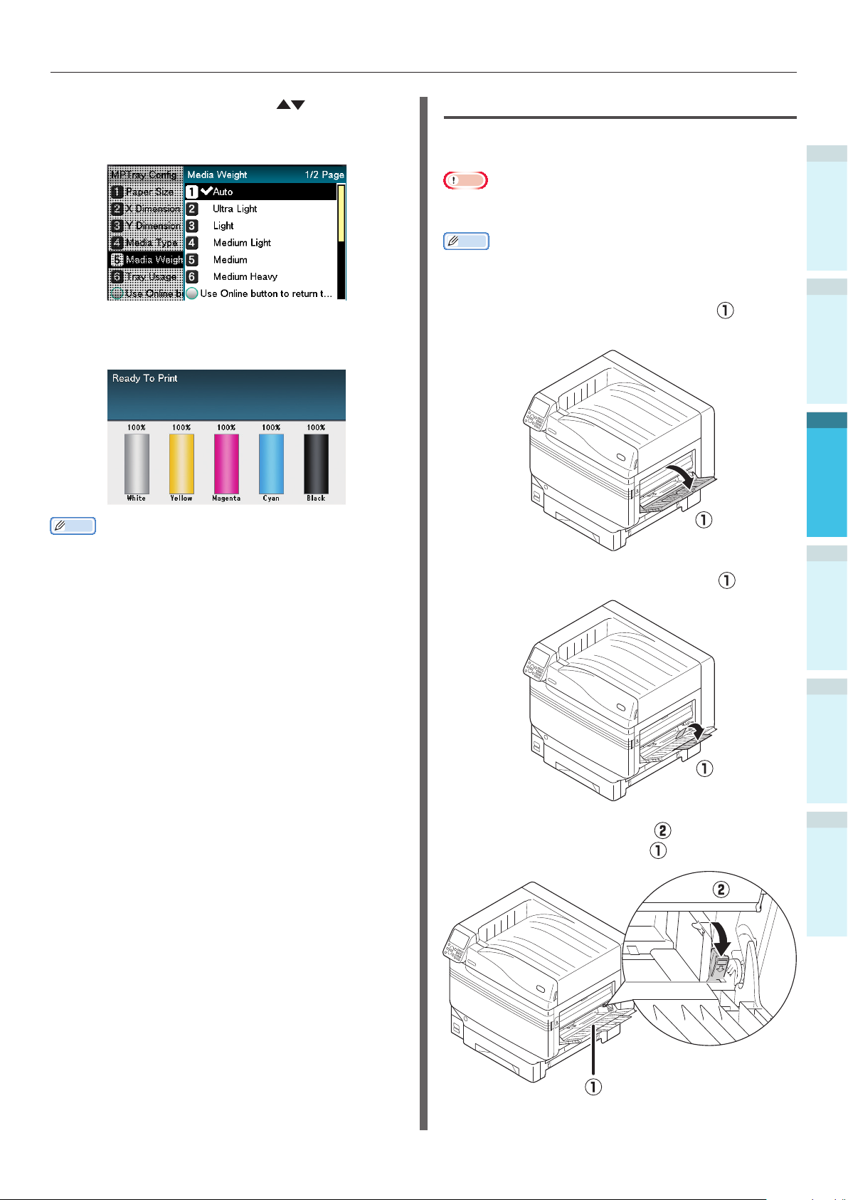
Printing from the Multi-Purpose Tray
Press the scroll buttons to select
9
the size of the paper that has been set,
and press the [OK] button.
Press the [BACK] button several times
10
to return to the standby screen.
Setting Paper
The multi-purpose tray prints to the face-up side
of the paper that has been set.
Note
Do not collate and set paper of different sizes, types, and
thicknesses at the same time.
Memo
If setting custom size paper, it is necessary to register the
size. For details, see "Advanced".
Open the multi-purpose tray ( )
1
towards you.
1
Before Use
2
Setting Up
3
Printing
Memo
Press the [CANCEL] button to return to the standby
screen.
Open the auxiliary supporter ( ).
2
Pull the setting lever ( ) on the right of
3
the paper supporter (
) towards you.
4
Basic Device Operations
Appendix
Index
- 85 -
Page 86

Printing from the Multi-Purpose Tray
4
1
Before Use
2
5
3
Printing
Adjust the paper guide ( ) to the width
of the paper that has been set.
Thoroughly sort the paper. Carefully
align the ends of the paper horizontally.
Adjust the paper guide to t the width
7
of the paper that has been set.
Release and return the setting lever ( )
8
to its original position.
Place the print side face-up, and set the
4
6
Basic Device Operations
AppendixSetting Up
Index
paper.
Note
Do not set the paper beyond the MP paper guide ( ).
Note
When adding paper, remove the paper in the multi-
purpose tray, and align the additional paper top, bottom,
left, and right before setting.
Do not take out or add paper while printing.
Do not place anything other than the paper to be printed
on the multi-purpose tray, apply pressure from above, or
apply unnecessary force.
The paper supporter will automatically lift up when the
paper is set in place. If the paper supporter gets in your
way of setting paper in the tray, place paper after opening
the toner replacement cover, and then close the cover
when it is set in place.
- 86 -
Page 87
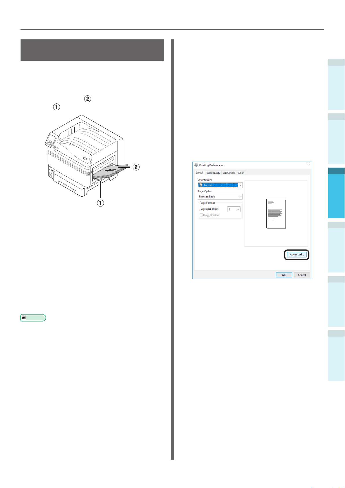
Printing from the Multi-Purpose Tray
Printing from the MultiPurpose Tray
Print to the paper set in the multi-purpose tray.
The main operating procedures are described
below.
Set the paper ( ) in the multi-purpose
1
tray (
).
Using Windows PS Printer Driver
Open the le to be printed using
1
WordPad.
Click [Page Setup] in the [File] menu.
2
Select the paper size and print
3
orientation, and click [OK].
Click [Print] in the [File] menu.
4
Click [Preferences].
5
Click [Advanced] in the [Layout] tab.
6
1
Before Use
2
Setting Up
3
Printing
Open the le to be printed.
2
Specify the [Multi-Purpose Tray] using
3
the printer drivers to print.
This section explains how to print using the
multi-purpose tray from the printer drivers.
Windows PS printer driver
Mac OS X printer driver (P.89)
Further, this explanation uses "WordPad" for
Windows as the application used. For Mac OS X,
the example uses "TextEdit".
Reference
For how to install the printer drivers, see “Connecting the
PC” (P.55).
4
Basic Device Operations
Appendix
Index
- 87 -
Page 88
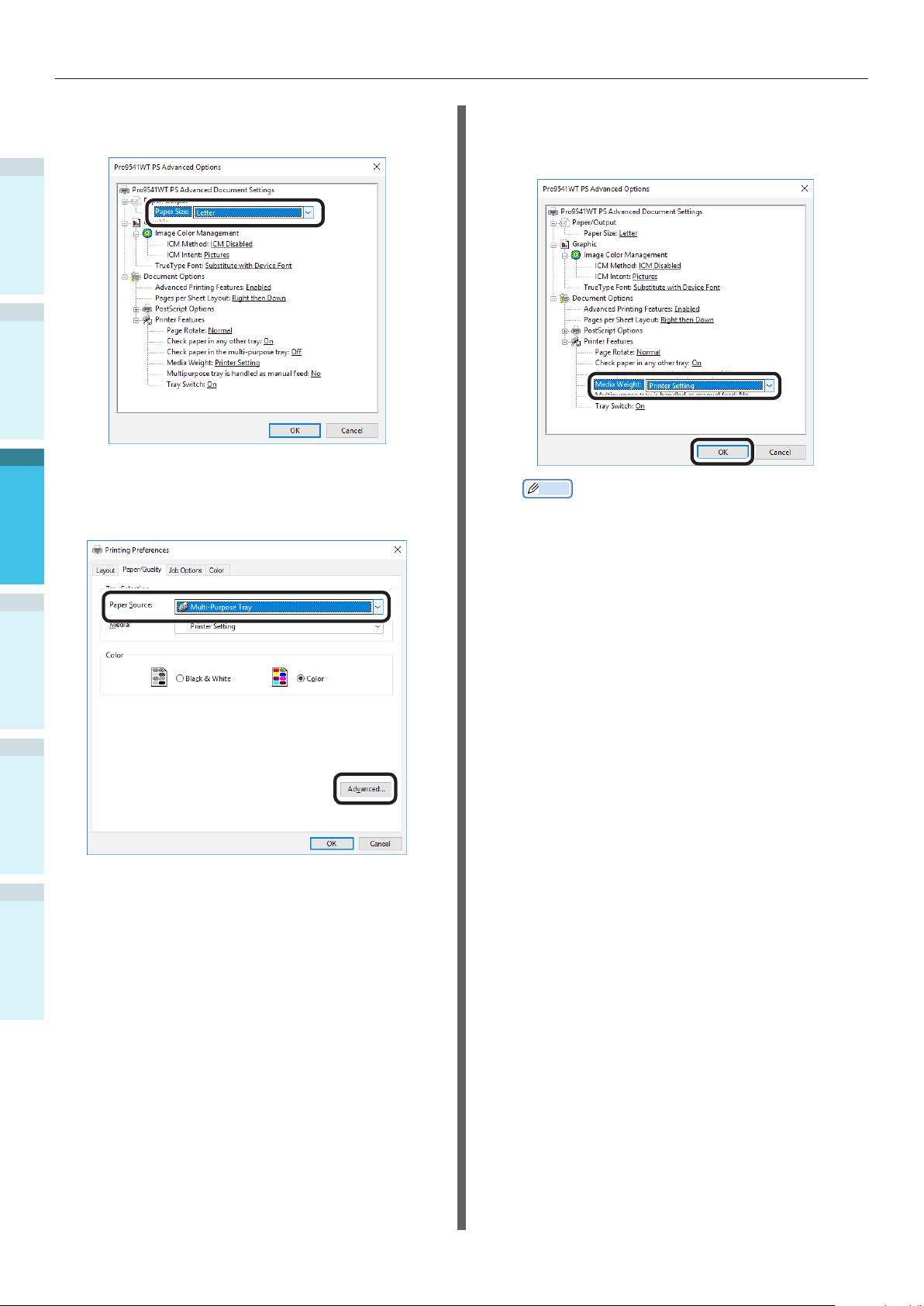
Printing from the Multi-Purpose Tray
7
1
Before Use
2
3
8
Printing
Select [Paper Size] from [Paper/Output]
in the "Advanced Options" tab.
Select [Multi-Purpose Tray] in [Paper
Source] in the [Paper/Quality] tab, and
click [Advanced].
Select a suitable value from [Media
9
Weight] in the "Advanced Options"
screen, and then click [OK].
Memo
Normally, select [Auto]. Select [Auto] to use the
value set using the printer control panel.
To print pages individually, set [Multipurpose tray is
handled as manual feed] to [Yes].
4
Basic Device Operations
AppendixSetting Up
Index
Click [OK] in the "Printing Preferences"
10
screen.
Click [Print] in the "Print" screen to
11
print.
- 88 -
Page 89

Printing from the Multi-Purpose Tray
Using Mac OS X Printer Driver
Open the le to be printed using
1
TextEdit.
Click [Page Setup] in the [File] menu.
2
Select the paper size and print
3
orientation using the page setup dialog
box, and click [OK].
Select [Print] in the [File] menu.
4
Select [Paper Feed] in the print dialog
5
box.
Select [Print Options] using the print
7
dialog box.
Chick the [Feed] tab in the printer
8
setup panel, and select [Media Type]
and [Media Weight].
1
Before Use
2
Setting Up
3
Printing
Select [Multi-Purpose Tray] in [All Pages
6
From].
Memo
Normally, select [Auto]. Select [Auto] to use the
value set using the printer control panel.
Click [Print] to print.
9
4
Basic Device Operations
Appendix
Index
- 89 -
Page 90

Outputting Paper
Outputting Paper
The printer outputs the paper either to the face-down stacker or the face-up stacker.
1
The face-down stacker can accumulate approx. 620 sheets of GMS 64g/m
Before Use
The face-up stacker can accumulate approx. 300 sheets of GMS 64g/m
2
paper.
2
paper.
Using the Face-Down Stacker
(Print Face Is Down)
2
The paper is output with the print side facedown. Papers are stacked in the order in which
they are printed.
To output from the face-down stacker, specify
the face-down stacker in "Output Bin" using the
printer drivers.
3
Using Windows PS Printer Driver
Printing
Open the le to be printed.
1
Click [Preferences] in the "Print" screen.
2
4
Basic Device Operations
Select [Stacker (Face-down)] in [Output
3
Bin] in the [Job Options] tab, and click
[OK].
Using Mac OS X Printer Driver
Memo
This section uses "TextEdit" as an example.
Open the le to be printed.
1
Select [Print] in the [File] menu.
2
Select [Print Options] using the print
3
dialog box.
Select [Stacker (Face-down)] in [Output
4
Bin] in the [Paper] tab.
AppendixSetting Up
Index
4
Implement printing.
Click [Print] to print.
5
The printed paper will be output to the
6
face-down stacker (output tray) (
).
- 90 -
Page 91

Outputting Paper
Using the Face-Up Stacker
(Print Face Is Up)
The paper is output with the print side faceup. Paper is stacked in the reverse order from
printing.
To output from the face-up stacker, specify the
face-up stacker in "Output Bin" using the printer
drivers.
Open the face-up stacker ( ) on the
1
left of the printer.
Open the le to be printed.
4
Customers using Mac OSX go to “Using
Mac OS X Printer Driver” Step 5.
Click [Advanced] in the "Print" screen.
5
Using Windows PS Printer Driver
Select [Stacker (Face-up)] in [Output
6
Bin] in [Job Options], and click [OK].
1
Before Use
2
Setting Up
3
Printing
Open the paper supporter ( ) as
2
shown in the diagram.
Rotate the auxiliary supporter ( ) in
3
the direction of the arrow until its lock
position.
Implement printing.
7
4
Basic Device Operations
Appendix
Index
- 91 -
Page 92

Outputting Paper
Using Mac OS X Printer Driver
Memo
This section uses "TextEdit" as an example.
1
Before Use
5
6
2
7
3
Printing
4
Basic Device Operations
Select [Print] in the [File] menu.
Select [Print Options] using the print
dialog box.
Select [Stacker (Face-up)] in [Output
Bin] in the [Paper] tab.
8
AppendixSetting Up
Index
Click [Print] to print.
Printed paper is output to the face-up
stacker (
).
- 92 -
Page 93

Setting Power Save Mode
4. Basic Device Operations
This chapter explains how to set power save mode, which reduces device power consumption, how
to check print quantities, the service life of consumables, remaining maintenance unit quantities and
service life, and how to cancel printing.
You can set the printer to enter power save mode from the standby screen. Further, you can also set
the printer to enter sleep mode from power save mode.
Setting Power Save Mode
1
Before use
2
Setting Power Save Mode
The device can be set to enter power save mode
from standby mode when no printing or data has
been received after a xed period of time.
The default factory setting is to enable power
save, so implementing this procedure is
unnecessary.
Press the scroll button or .
1
Select [Admin Setup], and press the
2
[OK] button.
Enter the administrator password, and
3
press the [OK] button.
Memo
In the default factory settings, the administrator
password is [aaaaaa].
Select [Power Setup], and press the
4
[OK] button.
3
Printing
4
Basic Device Operations
AppendixSetting Up
- 93 -
Select [Power Save], and press the [OK]
5
button.
Index
Page 94

Setting Power Save Mode
6
1
Before use
2
Setting Up
7
3
Printing
Select [Enable], and press the [OK]
button.
Press the [ON LINE] button to return to
the standby screen.
Setting the time before the
printer enters power save mode
You can set the time until power save mode is
entered.
The default factory setting is "1 min."
Lengthening the time until power save mode
is entered may shorten the time until printing
starts.
Press the [Fn] key.
1
The numerical values input screen will
be displayed.
Enter [2], [0], [0], and press the [OK]
2
button.
4
Basic Device Operations
Appendix Index
Memo
Other items can also continue to be set before
pressing the [ON LINE] button.
Select the time to be set, and press the
3
[OK] button.
- 94 -
Page 95

Setting Power Save Mode
Press the [ON LINE] button to return to
4
the standby screen.
Memo
The settable times are described below.
1 min., 2 mins., 3 mins., 4 mins., 5 mins., 10 mins.,
15 mins., 30 mins., 60 mins.
Setting sleep mode
The device can be set to enter sleep mode from
power save mode when no printing or data has
been received after a xed period of time.
The default factory setting is to enable sleep, so
implementing this procedure is unnecessary.
Press the scroll button or .
1
Select [Admin Setup], and press the
2
[OK] button.
1
Before use
2
3
Printing
Enter the administrator password, and
3
press the [OK] button.
Memo
In the default factory settings, the administrator
password is [aaaaaa].
Select [Power Setup], and press the
4
[OK] button.
4
Basic Device Operations
AppendixSetting Up
Index
- 95 -
Page 96
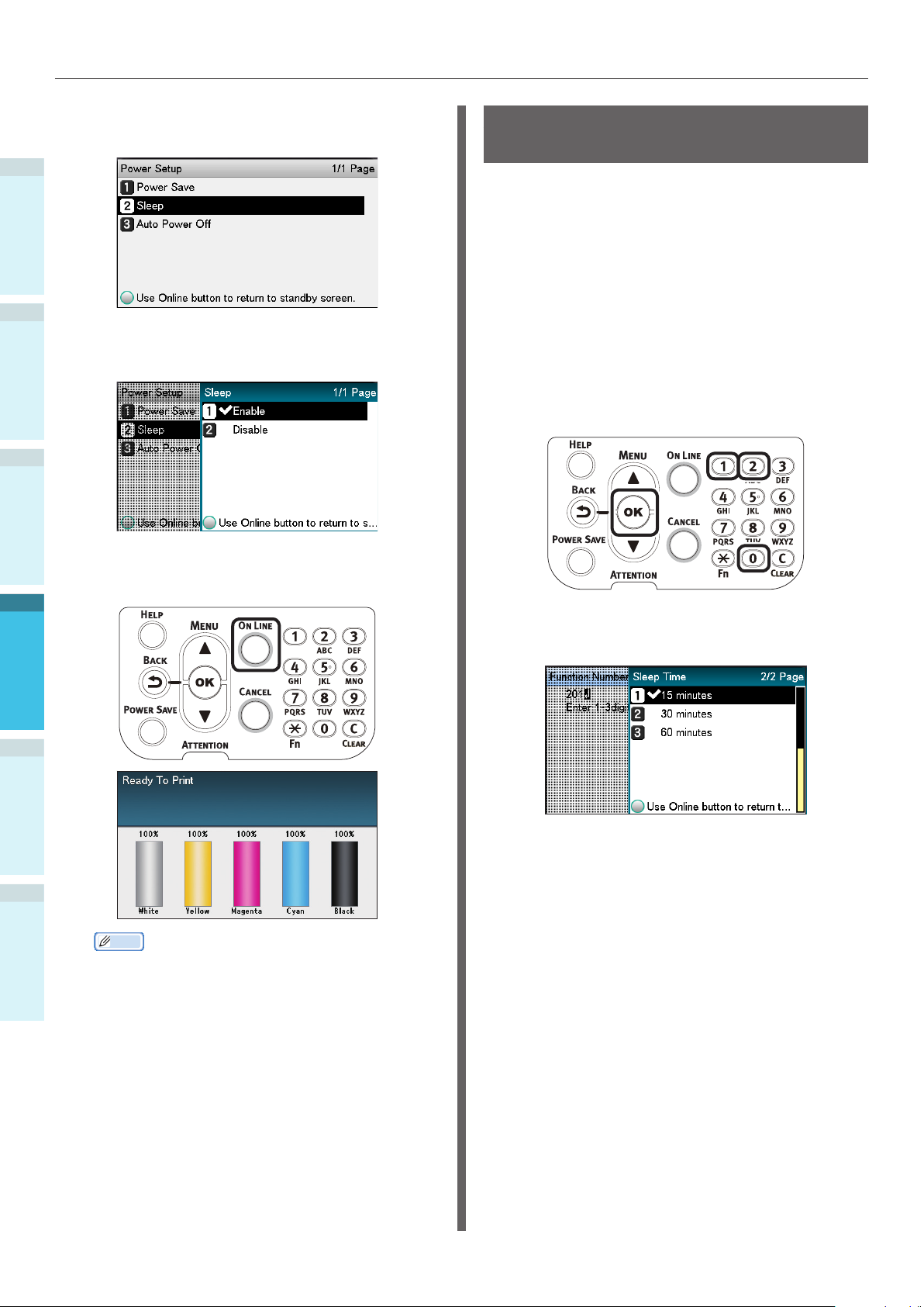
Setting Power Save Mode
5
1
Before use
2
Setting Up
6
3
Printing
7
4
Basic Device Operations
Select [Sleep], and press the [OK]
button.
Select [Enable], and press the [OK]
button.
Press the [ON LINE] button to return to
the standby screen.
Setting the time before the
printer enters sleep mode
You can set the time until sleep mode is entered.
The default factory setting is "15 mins."
Lengthening the time until sleep mode is entered
may shorten the time until printing starts.
Press the [Fn] key.
1
The numerical values input screen will
be displayed.
Enter [2], [0], [1], and press the [OK]
2
button.
Select the time to be set, and press the
3
[OK] button.
Appendix Index
Memo
Other items can also continue to be set before
pressing the [ON LINE] button.
- 96 -
Page 97
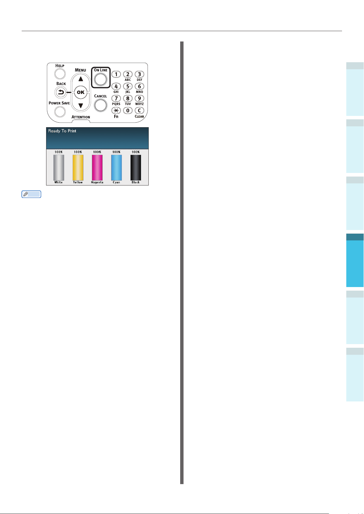
Press the [ON LINE] button to return to
4
the standby screen.
Setting Power Save Mode
1
Before use
2
3
Memo
The settable times until sleep mode is entered are
described below.
1 min., 2 mins., 3 mins., 4 mins., 5 mins., 10 mins.,
15 mins., 30 mins., 60 mins.
Printing
4
Basic Device Operations
AppendixSetting Up
Index
- 97 -
Page 98

Setting Power Save Mode
Restrictions in sleep mode
This section explains the restrictions when the device is in sleep mode.
1
When the device is displaying an error, entering sleep mode may be disabled.
Before use
Printer driver utility restrictions
When the device enters sleep mode, the printer driver and utility functions are restricted as described
below.
2
Setting Up
3
Printing
OS Software name Restrictions in sleep mode
Windows Conguration Tool Network settings for the Network Setting plug-in are disabled.
Network Extension
Driver installer
Mac OS X NIC Setup Tool
Printer drivers Printing is disabled when connected using EtherTalk. Connect to the
Cannot connect to
When connected to a network, the
acquired while installing the printer drivers.
Printer
device using either Bonjour (Rendezvous) protocols or LPD protocols
(TCP/IP).
For advanced setup methods, see either “Using Bonjour (Rendezvous)”
(P.70) or “Adding Printers Using LPD (TCP/IP) Protocols” (P.105).
searches and settings are disabled.
device
.
device
options information cannot be
When the device enters sleep mode, press the [POWER SAVE] button on the control panel to check that
"Printing enabled" is displayed on the liquid crystal panel.
When "Printing enabled" is displayed, the restrictions described above do not apply.
4
Basic Device Operations
Appendix Index
- 98 -
Page 99

Setting Power Save Mode
Network function restrictions
In sleep mode, the following restrictions apply to
the network functions.
Sleep mode is disabled
In the following cases, the device cannot enter
sleep mode.
IPSec is enabled.
A TCP connection has been established.
Example: A connection has been established
using Telnet or FTP, etc.
After the period for entry to power save mode
has elapsed in energy save mode, the printer will
enter sleep mode when the connection is cut.
E-mail receiving is enabled.
Memo
To enable sleep mode, disable IPSec/E-mail.
Unable to print
While in sleep mode, printing using the following
protocols is disabled.
NBT
EtherTalk*
Protocols with client functions do
not operate
While in sleep mode, the following protocols with
client functions do not operate.
E-mail alert
*1
SNMP Trap
WINS
*1: The elapsed time while in sleep mode does not include
*2: The elapsed time while in sleep mode does not include
*2
the intervals between periodic communications times for
e-mail alerts.
the intervals between WINS refresh times.
WINS is not periodically refreshed while in sleep mode,
so the names registered to the WINS server may be
deleted.
Moving automatically from sleep
mode to power save mode
In network environments with ows of large
packet quantities, the device may move
automatically from sleep mode to power save
mode and respond.
Subsequently, if the period for moving to
sleep mode elapses, sleep mode is entered
automatically.
1
Before use
2
3
Printing
4
Basic Device Operations
WSD Print
*: For Mac OS X, printing while in sleep mode is possible if
connected using Bonjour (Rendezvous) protocols or "LPD
protocols (TCP/IP)".
For setup methods, see either “Using Bonjour
(Rendezvous)” (P.70) or “Adding Printers Using LPD
(TCP/IP) Protocols” (P.105).
Unable to search/setup
While in sleep mode, searches and settings
using the following functions and protocols are
disabled.
PnP-X
UPnP
LLTD
MIB*
*: Referencing using the parts of MIB (Get command) that
are supported is possible is sleep mode.
AppendixSetting Up
Index
- 99 -
Page 100

Setup to Turn OFF the Power Supply Automatically
Setup to Turn OFF the Power Supply Automatically
1
Setting auto power OFF
Before use
mode
The device can be set to enter OFF mode
automatically when no printing or data has been
received after a xed period of time.
2
In the default factory settings, auto power OFF
mode is set automatically. Set according to the
Setting Up
conditions for entering OFF mode.
"Enable": Enters OFF mode automatically
"Auto Cong":
3
"Disable": The power supply does not turn OFF
Printing
Press the scroll button or .
Enters OFF mode when the set time has
elapsed. If using a network connection,
however, OFF mode is not entered even
when the set time has elapsed.
automatically.
1
4
Basic Device Operations
Select [Power Setup], and press the
4
[OK] button.
Select [Auto Power Off], and press the
5
[OK] button.
Select [Enable] or [Auto Cong], and
6
press the [OK] button.
Appendix Index
Select [Admin Setup], and press the
2
[OK] button.
Enter the administrator password, and
3
press the [OK] button.
Memo
In the default factory settings, the administrator
password is [aaaaaa].
- 100 -
 Loading...