

Page 1

OKIPOS 425S/D
(OKI Standard Version)
POS-PRINTER
Product Specifications
(Software edition)
2001-05-10 Rev.3
41049421PS Rev.3 1 / 221
Page 2
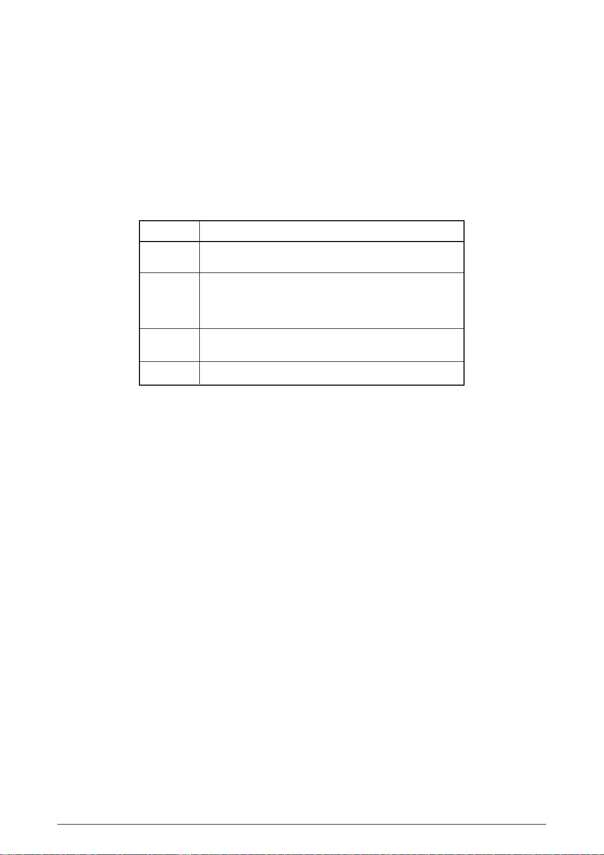
Document Revision History
Rev.No. Date
Corrected items
No.
Page Description of change
1 2001-01-17 ISSUE ODS Kanno
2 2001-02-28 ALL Review in entirely and ODS Kanno
update
3 2001-05-10 ALL Addition of Bar Code ODS Kanno
Command and update
Person in
charge
41049421PS Rev.3 2 /
Page 3

CONTENTS
1. OVERVIEW ......................................................................................................... 7
2. OPERATOR CONTROL ..................................................................................... 8
2.1 Operator Panel Functions................................................................................................... 8
2.1.1 Operator Panel Specifications................................................................................ 8
2.2 LOCAL FUNCTIONS ........................................................................................................ 12
2.2.1 Kinds of Local Functions and How to Start........................................................... 12
2.3 LOCAL TEST.................................................................................................................... 13
2.3.1 Printer Status in Local Test Mode ........................................................................ 13
2.3.2 Details of Local Test Prints................................................................................... 13
2.3.2.1 All Letter and Rolling ASCII Continuous Print Test (Receipt) ............... 13
2.3.2.2 All Letter and Rolling ASCII Continuous Print Test (Journal)................ 14
2.3.2.3 All Letter and Rolling ASCII Continuous Print Test (Receipt + Journal) 14
2.3.2.4 All Letter and Rolling ASCII Continuous Print Test (Slip/Sprocket) ...... 15
2.3.2.5 Sample Data Continuous Print Test (Validation)................................... 15
2.3.2.6 MICR Read Test (Receipt).................................................................... 16
2.3.2.7 Rewinder Winding Evaluation Continuous Print Test (Journal) ............ 17
2.3.3 Local Test Header ................................................................................................ 18
2.4 MENU FUNCTION (Receipt) ............................................................................................ 19
2.4.1 Overview............................................................................................................... 19
2.4.2 Menu Items........................................................................................................... 19
2.4.3 How to Operate .................................................................................................... 21
2.4.3.1 Start....................................................................................................... 21
2.4.3.2 Operation .............................................................................................. 21
2.5 HEX DUMP FUNCTION (Receipt).................................................................................... 22
2.5.1 Print Format.......................................................................................................... 22
2.5.2 How to Print.......................................................................................................... 22
2.6 PLATEN MAINTENANCE MODE..................................................................................... 23
3. COMMAND DESCRIPTION.............................................................................. 24
3.1 Control Code..................................................................................................................... 24
3.1.1 Control Code List.................................................................................................. 24
3.1.1.1 Function Code....................................................................................... 24
3.1.1.2 DLE Sequence ...................................................................................... 24
3.1.1.3 ESC Sequence...................................................................................... 25
3.1.1.4 FS Sequence ........................................................................................ 27
3.1.1.5 GS Sequence........................................................................................ 27
3.2 Control Operations............................................................................................................ 28
3.2.1 Print Operation Control......................................................................................... 28
3.2.1.1 Print/Carriage Return ............................................................................ 28
3.2.2 Space Control....................................................................................................... 29
3.2.2.1 Left Margin Set...................................................................................... 29
3.2.2.2 Absolute Position Designate ................................................................. 30
3.2.2.3 Relative Position Designate .................................................................. 31
3.2.2.4 Position Align ........................................................................................ 33
3.2.2.5 Journal Tab ........................................................................................... 33
3.2.3 Line Feed Control................................................................................................. 34
3.2.3.1 Print/Line Feed...................................................................................... 34
3.2.3.2 1/8-inch Line Feed Set .......................................................................... 35
3.2.3.3 7/72-inch Line Feed Set ........................................................................ 35
3.2.3.4 1/6-inch Line Feed Set .......................................................................... 36
3.2.3.5 n/144-inch Line Feed Pitch Set ............................................................. 36
3.2.3.6 n/72-inch Line Feed Pitch Set ............................................................... 37
3.2.3.7 Cut Sheet Paper Print and Eject or Sprocket Paper Form Feed........... 37
3.2.3.8 Sprocket Paper Page Length Set.......................................................... 38
3.2.3.9 Sprocket Paper Perforation Skip Set .................................................... 39
41049421PS Rev.3 3 /
Page 4

3.2.3.10 Sprocket Paper Perforation Skip Reset ................................................ 40
3.2.3.11 n/144-inch Paper Feed.......................................................................... 40
3.2.3.12 n-line Paper Feed.................................................................................. 41
3.2.3.13 n/144-inch Paper Feed.......................................................................... 41
3.2.3.14 n/144-inch Line Feed Pitch Set ............................................................. 42
3.2.4 Character Control ................................................................................................. 43
3.2.4.1 International Character Set Select ........................................................ 43
3.2.4.2 Character Code Table Select................................................................ 44
3.2.5 Print Mode Control................................................................................................ 45
3.2.5.1 Character Right-side Space Set............................................................ 45
3.2.5.2 Underline Designate/Clear .................................................................... 46
3.2.5.3 Double Height Print Set/Reset .............................................................. 46
3.2.5.4 Double Width Print Set/Reset ............................................................... 47
3.2.5.5 Italic Mode Set ...................................................................................... 47
3.2.5.6 Italic Mode Reset .................................................................................. 48
3.2.5.7 Emphasized Print Designate/Clear ....................................................... 48
3.2.5.8 Double Strike Print Designate/Clear ..................................................... 49
3.2.5.9 Blanket Print Mode Designate............................................................... 49
3.2.5.10 Condense Designate............................................................................. 50
3.2.5.11 Condense Designate............................................................................. 50
3.2.5.12 Condense Clear .................................................................................... 50
3.2.6 Image Control....................................................................................................... 51
3.2.6.1 Bit Image Mode Designate.................................................................... 51
3.2.6.2 9-Pin Bit Image Mode Designate .......................................................... 53
3.2.7 Print Sheet Control ............................................................................................... 56
3.2.7.1 Print Sheet Select ................................................................................. 56
3.2.7.2 Set Sheet Select ................................................................................... 57
3.2.7.3 Paper Sensor Select Enabling Paper End Signal ................................. 58
3.2.7.4 Print Stop Sensor Select ....................................................................... 59
3.2.7.5 Cut Form Wait Time Set........................................................................ 60
3.2.7.6 Full Cut.................................................................................................. 61
3.2.7.7 Partial Cut (one point left intact)............................................................ 61
3.2.7.8 Receipt+Journal Same Data Print Designate/Clear.............................. 61
3.2.7.9 Print Sheet Select ................................................................................. 62
3.2.7.10 Set Sheet Select ................................................................................... 64
3.2.8 Printer Hardware Control...................................................................................... 65
3.2.8.1 Peripheral Device Select....................................................................... 65
3.2.8.2 Peripheral Device Status Send ............................................................. 67
3.2.8.3 Panel Switch Enable/Disable ................................................................ 68
3.2.8.4 Print Data Cancel .................................................................................. 69
3.2.8.5 Printer Initialize...................................................................................... 69
3.2.8.6 Unidirectional Print Designate/Clear ..................................................... 70
3.2.8.7 One Line Unidirectional Print ................................................................ 70
3.2.8.8 Paper Sensor Status Send.................................................................... 71
3.2.8.9 Menu Item Set....................................................................................... 73
3.2.8.10 Print Speed and Head Currerent Run Time Set.................................... 75
3.2.8.11 Desiganted Pulse Generate (Open Cash Drawer)................................ 76
3.2.8.12 Auto Status Send Enable/Disable ......................................................... 77
3.2.8.13 Printer Status Real-time Send............................................................... 82
3.2.8.14 Printer ID Send...................................................................................... 84
3.2.8.15 Status Send........................................................................................... 86
3.2.8.16 Status Real-time Sent ........................................................................... 89
3.2.8.17 Real-time Request to Printer................................................................. 93
3.2.8.18 Real-time MICR Status Send ................................................................ 95
3.2.8.19 Check Paper Read (MICR Mode Select) .............................................. 96
3.2.8.20 Paper Load to Print Start Position....................................................... 100
3.2.8.21 Check Paper Eject .............................................................................. 100
3.2.8.22 Check Paper Read Result Re-send Request...................................... 101
3.2.8.23 Validation Insert Position Select.......................................................... 102
3.2.8.24 Auto Status Send Enable/Disable ....................................................... 103
3.2.8.25 Status Real-time Send ........................................................................ 105
41049421PS Rev.3 4 /
Page 5

3.2.9 Bar Code Control................................................................................................ 106
3.2.9.1 Bar Code Style Select and Size Set.................................................... 106
3.2.9.2 Print Bar Code Data ............................................................................ 116
3.3 Character set .................................................................................................................. 129
3.3.1 Code table .......................................................................................................... 129
3.3.1.1 USA..................................................................................................... 129
3.3.1.2 Canada-French ................................................................................... 130
3.3.1.3 Multilingual .......................................................................................... 131
3.3.1.4 Portugal............................................................................................... 132
3.3.1.5 Norway ................................................................................................ 133
3.3.1.6 BRASCII.............................................................................................. 134
3.3.1.7 Abicomp .............................................................................................. 135
3.3.1.8 Multilingual 858 ................................................................................... 136
3.3.1.9 ISO 8859/15 ........................................................................................ 137
3.3.1.10 International character set table.......................................................... 138
3.3.2 Spec ................................................................................................................... 139
3.3.3 Character development ...................................................................................... 140
3.4 Operation ........................................................................................................................ 142
3.4.1 Default ................................................................................................................ 142
3.4.2 Print Start............................................................................................................ 145
3.4.2.1 Conditions for Print Start ..................................................................... 145
3.4.3 Right Margin Process ......................................................................................... 146
3.4.4 Combination of print mode ................................................................................. 149
3.4.5 Print Pass Position Control................................................................................. 151
4. IEEE1284 SPECIFICATIONS ......................................................................... 152
4.1 Terminology .................................................................................................................... 152
4.2 I EEE1284....................................................................................................................... 153
4.3 Compatible Mode............................................................................................................ 154
4.3.1 Compatible Mode Handshake ............................................................................ 155
4.3.1.1 Compatible mode handshake timing chart.......................................... 155
4.3.1.1.1 Data receive (forward data transfer phase) ....................... 155
4.3.1.1.2 Initialization by POWER ON .............................................. 155
4.3.1.1.3 Initialization by I-PRIME (nlnit) signal ................................ 155
4.3.1.1.4 Paper end .......................................................................... 156
4.3.1.1.5 Recoverable alarm............................................................. 156
4.3.1.1.6 Fatal alarm......................................................................... 157
4.3.1.1.7 Feed SW hold down .......................................................... 157
4.3.1.2 Negotiation phase start ....................................................................... 157
4.4 Negotiation...................................................................................................................... 158
4.4.1 Details of Negotiation ......................................................................................... 158
4.4.1.1 Negotiation and handshake ................................................................ 159
4.4.1.2 Negotiation timing chart ...................................................................... 160
4.5 Nibble Mode.................................................................................................................... 164
4.5.1 Nibble Mode Handshake .................................................................................... 165
4.5.1.1 Nibble mode handshake timing charts ................................................ 166
4.6 Interface Errors ............................................................................................................... 177
4.6.1 Interface Error Timing Charts ............................................................................. 178
4.7 DEVICE ID...................................................................................................................... 184
4.7.1 Device ID Format................................................................................................ 184
4.7.2 Device ID Data ................................................................................................... 185
4.7.3 Error control during device ID data transfer........................................................ 185
4.8 NIBBLE MODE REVERSE CHANNEL TRANSFER ...................................................... 186
4.8.1 Reverse channel transfer data ........................................................................... 186
4.8.1.1 Transfer priority of reverse channel transfer data ............................... 186
4.8.2 Error control while reverse channel transfer data is being transferred............... 187
4.8.2.1 Control when status other than ASB is being transferred ................... 187
4.8.2.2 Control when ASB is being transferred ............................................... 187
4.8.2.3 Control while MICR read data is being transferred ............................. 188
4.8.2.4 Control while ASB/non-ASB mixed data is being transferred ............ 189
41049421PS Rev.3 5 /
Page 6

4.9 Interface Iinitialization ..................................................................................................... 190
4.9.1 I/F Signals During Initialization .......................................................................... 190
4.10 Status Transition Diagram .............................................................................................. 192
4.11 ASB performance ........................................................................................................... 193
5. RS-232C SPECIFICATIONS........................................................................... 195
5.1 Receive Buffer ................................................................................................................ 195
5.1.1 Receive Buffer Size............................................................................................ 195
5.1.2 Receive buffer structure ..................................................................................... 195
5.2 Serial Interface................................................................................................................ 196
5.2.1 Explanation of Interface Signal and Pins............................................................ 196
5.2.2 Interface Cable Wiring Diagram ......................................................................... 197
5.2.2.1 Wiring diagram when the host side serial board connector is D-SUB 9-pin.. 197
5.2.2.2 Wiring diagram when the host side serial board connector is D-SUB 25-pin 197
5.2.3 Overview............................................................................................................. 198
5.2.4 RS-232C Interface.............................................................................................. 199
5.2.4.1 Signal level.......................................................................................... 199
5.2.4.2 Character structure on transmission circuit......................................... 199
5.2.4.3 BUSY signal timing chart .................................................................... 200
5.2.5 Receiving Margin................................................................................................ 200
5.3 Selecting a Function ....................................................................................................... 201
5.3.1 DIP switch structure............................................................................................ 201
5.3.1.1 Details of DIP switch functions............................................................ 202
5.3.2 Factory default.................................................................................................... 203
5.3.3 Receive data error check.................................................................................... 204
5.3.3.1 Parity check......................................................................................... 204
5.3.3.2 Framing error check ............................................................................ 205
5.3.3.3 Overrun error check ............................................................................ 206
5.3.4 DSR signal control.............................................................................................. 207
5.3.4.1 DSR signal when data is being received............................................. 207
5.3.4.2 DSR signal when data is being sent ................................................... 207
5.3.4.3 Printer status request command that monitors status of DSR signal.. 208
5.3.4.4 Printer status request command when DSR signal is in MARK status 209
5.3.5 Protocol .............................................................................................................. 210
5.3.5.1 Ready / Busy protocols ....................................................................... 210
5.3.5.2 X-ON / X-OFF protocol........................................................................ 211
5.3.6 Busy On timeout receive control......................................................................... 212
5.3.6.1 Behavior .............................................................................................. 212
5.3.6.2 BUSY ON timeout receive time chart.................................................. 213
5.3.7 Local test function............................................................................................... 215
5.3.7.1 Circuit test mode ................................................................................. 215
5.3.8 Custmer display.................................................................................................. 218
5.3.8.1 Customer display connection and RTS signal .................................... 218
5.3.8.2 Customer display connection/non-connection and RTS signal status 218
5.3.9 Printer reset signal.............................................................................................. 219
5.3.9.1 Printer Busy control when reset signal is received.............................. 219
5.3.9.2 Busy control in X-ON/X-OFF protocol ................................................. 220
5.3.9.2.1 H/W reset........................................................................... 220
5.3.9.2.2 F/W reset ........................................................................... 221
41049421PS Rev.3 6 /
Page 7

1. OVERVIEW
This specification defines the following that are realized by the firmware, for the OKIPOS 425S/D
(POS Printer) OKI Standard Version.
• OKIPOS 425S : OKI Single Standard Version
• OKIPOS 425D : OKI Dual Standard Version
<Conventions in this specification document>
This printer comes in two models, 1-Roll Model and 2-Roll Model. The 2-Roll Model printer has three
roll paper modes, Receipt, Journal, and Receipt+Journal. The 1-Roll Mode printer has only the Roll
paper mode.
In this specification document, if the 1-Roll Model is not specifically mentioned when the 1-Roll
Model is involved, for “Receipt (mode)”, read “Roll Paper (mode)”, and ignore the descriptions for
“Journal (mode)” or “Receipt+Journal (mode)”.
<Definitions of Off-line>
This printer is not equipped with the On-line/Off-line switch. It becomes Off-line under the following
conditions:
(1) During the period from POW ON or initialization of the mechanism prompted by the reset from
the interface, to the time communications become available.
(2) During execution of local test.
(3) When the cover is opened (“Cover Open Alarm” on the menu is set to “Yes”)
(4) During paper feed by the switch.
(5) Printing has stopped due to Paper End.
(Paper End of Receipt, Journal, or Receipt+Journal selected by ESC c4.)
(6) Recoverable Error has occurred.
(Except Head Thermal Alarm, SP Thermal Alarm or LF Thermal Alarm)
(7) Unrecoverable Error has occurred.
At Off-line, an On-line/Off-line status that is sent by GS a n, ESC DLE a Pno n, GS ENQ, DLE EOT
n, and ESC DLE r Pno n becomes off-line, and the I/F becomes Busy. In the case of (3) through
(6), the I/F becomes Busy only if “Off-line Busy Control” on the menu is set to “Yes”
* Each I/F becomes Busy in the following manner.
• With the Parallel model (Centronics I/F), the Busy signal becomes High at Off-line.
• With the Serial model (RS232C I/F), the following Busy control is performed at Off-line.
If handshake is DTR/DSR, the DTR signal will change to MARK.
If handshake is XON/XOFF, DC3 will be sent.
41049421PS Rev.3 7 /
Page 8
2. OPERATOR CONTROL
This specification document describes the details of the operator panel and the local functions that
are realized by the firmware.
2.1 Operator Panel Functions
This chapter describes the operator panel functions.
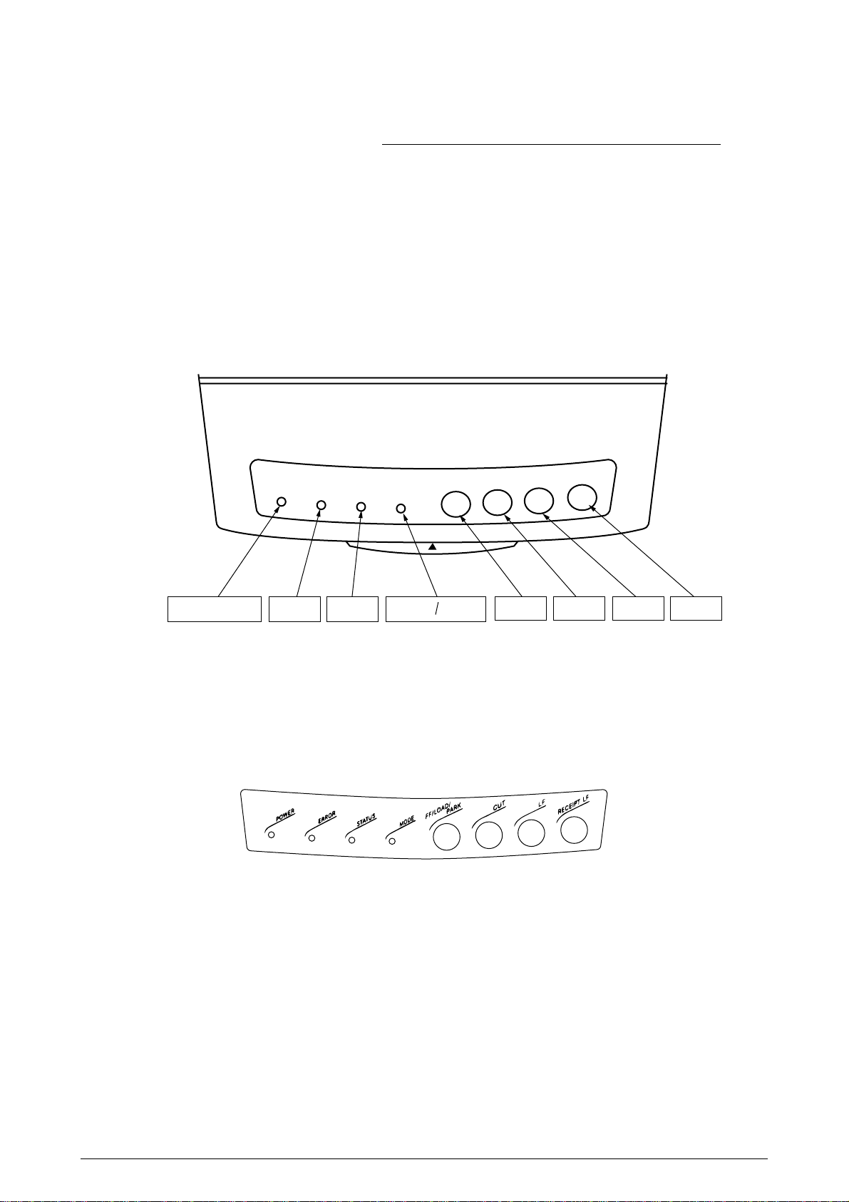
2.1.1 Operator Panel Specifications
(Operator Panel layout)
POWER LED LED1 LED2 SW2 SW3 SW1 SW4LED3 LED4
* The SW names in the above layout are tentative. They have been assigned to make their
explanations easy.
<Panel sheet design>
41049421PS Rev.3 8 /
Page 9
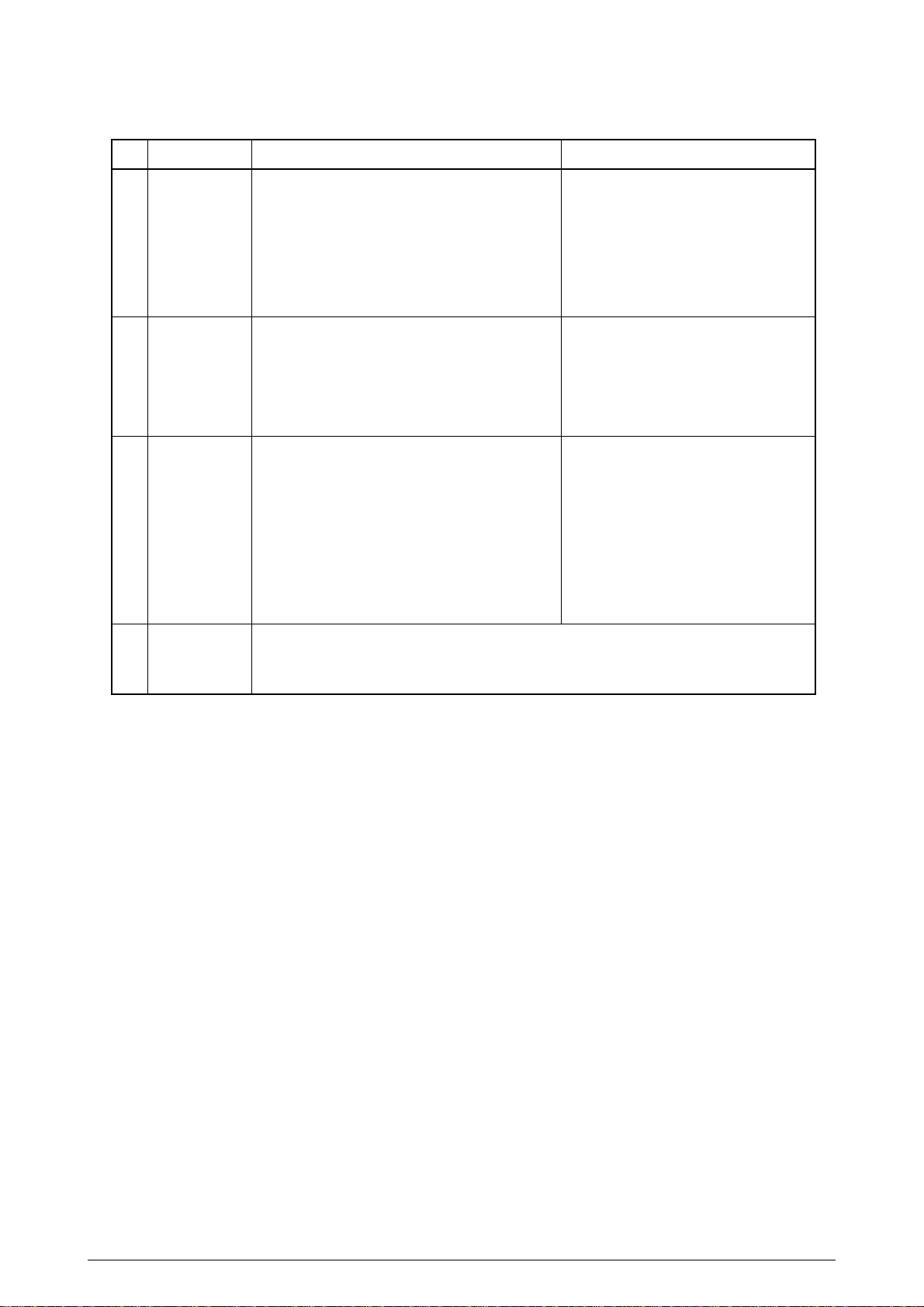
(Switch functions)
No.
1
2
3
Switch
SW2
(FF/LOAD/
PARK)
SW3
(CUT)
SW1
(LF)
Function in Modes other than Tractor Mode
In Receipt mode: Line-feeds receipts for a
fixed amount (10/6")
In Receipt+Journal mode: Same as above.
In Journal mode: Invalid.
In Slip mode: Ejects when paper is already
set.
In Validation mode: Invalid
* Does not cause printing to start.
Auto Cut (partial cut) Note 1)
* Valid regardless of print sheet mode or
print sheet status.
In Slip mode: Line-feeds the slip already set
by 1-line .
In Receipt mode: Line-feeds a jour nal by 1
line. Note 2)
In Validation mode: Invalid.
In Journal mode: Line-feeds a journal by 1line.
In Receipt+Journal mode: Line-feeds a
journal by 1-line.
* None of the above cause printing to start.
Function in Tractor Mode
Paper not loaded: Auto Load
Paper already loaded: Auto Park
* When No Paper is sensed by Slip
Sensor, Auto Park is invalid.
Cut position: Reverse-feeds to print
position.
Print position: Feeds to cut position.
Paper not loaded: Above does not
occur when pressed.
Single Press: Feeds Sprocket paper by 1-line.
Continuous Press: Form-feeds.
* Line-feeds 1-line immediately af-
ter the SW is pressed. Formfeeds after the SW is held down
continuously at least for 500ms.
* Does not cause printing to start.
4
SW4
(RECEIPT
Line-feeds a receipt by 1-line.
* Valid regardless of the print sheet mode or print sheet status.
LF)
Note 1)
Invalid when “Auto Cutter Unit = No” is set in the menu.
In the 1-Roll Model, Auto Cut function is invalid since this model does not have the auto
cutter unit.
Note 2)
In the 1-Roll Model, a receipt is line-fed by 1-line.
* When panel SW is set to invalid by Panel SW enable/disable command (ESC c5), the SW is
invalid.
* During the time between MICR read start and check paper eject, SW is invalid.
41049421PS Rev.3 9 /
Page 10
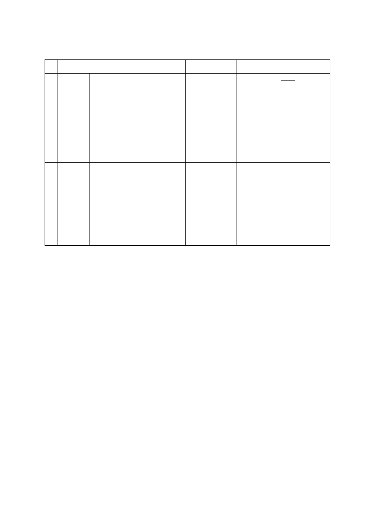
(LED display)
No.
1
2
3
4
LED ON
POWER
LED1
(ERROR)
LED2
(STATUS)
LED3/
LED4
(MODE)
Green
Red
Orange
Orange
Green
Powered on
Recoverable alarms
• Slip Load/Eject Alarm
• Auto loading Alarm
• Auto parking Alarm
• Media Does Not
Match Alarm (1)
• Media Does Not
Match Alarm (2)
• Cover Open Alarm
Note 1)
Paper not loaded (waiting for paper to be loaded) state
Slip Mode
Receipt+Journal Mode
Roll Paper Mode (1-Roll
Model)
OFF
Powered off
Normal state
Paper loaded
(ready for print)
state
Tractor Mode
BLINK
• Fatal alarms
(Alarm type is differentiated
by the number of times the
light blinks)
* Refer to the table on next
page.
• SP thermal alarm
(Blinks simultaneously with
LED2.)
• LF thermal alarm
• Waiting for removal
• SP thermal alarm
(Blinks simultaneously with
LED1.)
Validation mode
* Fast blinking
Receipt mode
* Fast blinking
MICR mode
* Slow blinking
Journal mode
* Slow blinking
Note 1)
When “Cover Open Alarm” is set to No in Menu, Cover Open Alarm does not happen
(Printing does not stop.)
* Media Does Not Match Alarm (1) is detected by monitoring the lever of the option tractor. Media
Does Not Match Alarm (2) is detected by the Validation sensor monitoring (media manually
inserted to the validation opening).
41049421PS Rev.3 10 /
Page 11
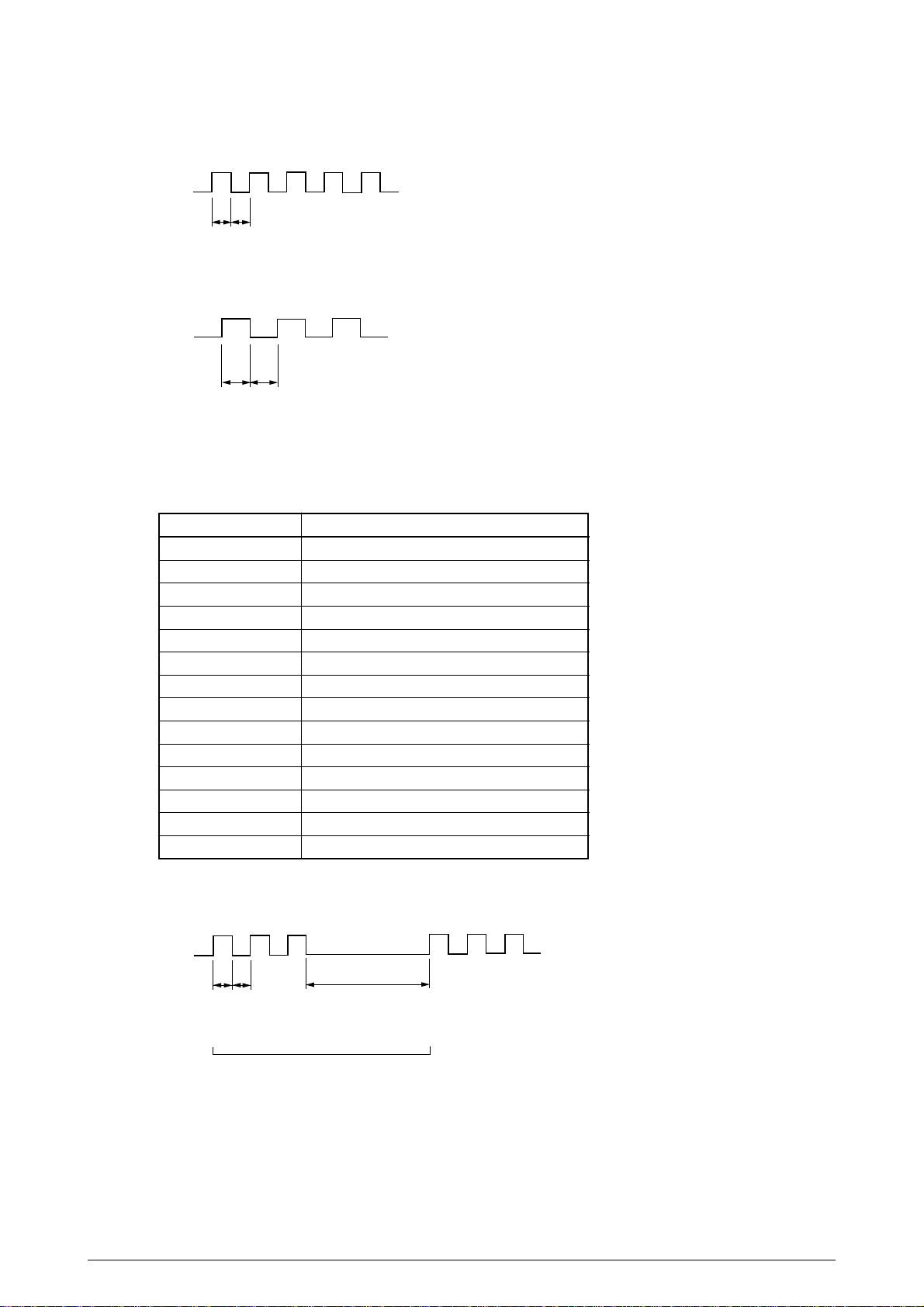
(Timing charts for LED1 and LED2 display for Waiting for removal and SP/LF thermal alarm state
and LED3 display for Validation mode and Receipt mode.)
LED
T1 T2
T1=T2=500msec
(LED3 display timing chart for MICR mode and Journal mode)
LED
T2T1
T1=T2=1sec
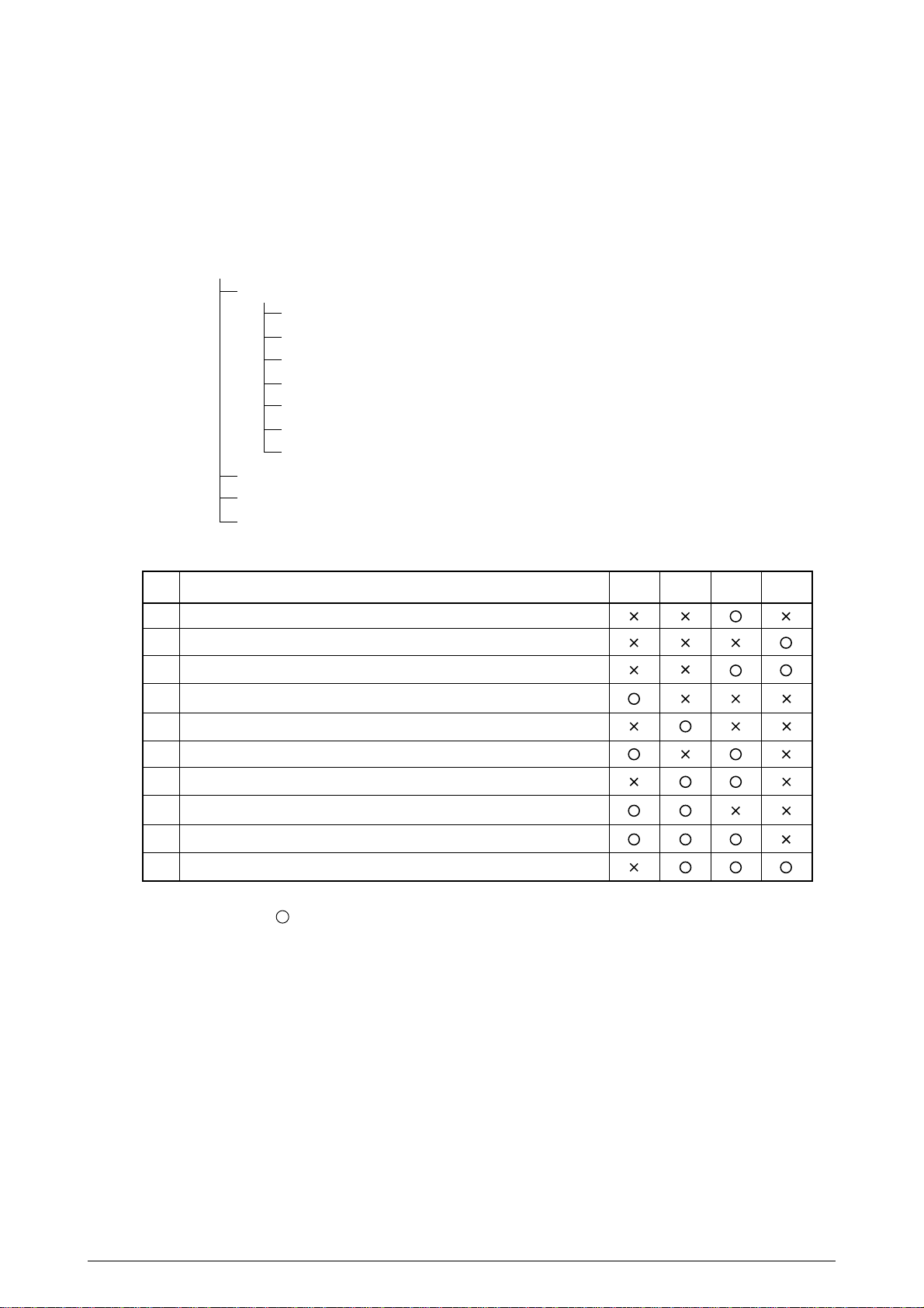
(Number of times LED1 blinks when fatal alarms have occurred)
Number of times Fatal alarm
1 Program ROM
2 EEPROM
3 Internal RAM
4 External RAM
5 Homing
6 Spacing
7 Auto Cutter
8 Platen Switch
9 Head A/D Error
10 WDT (F/W Control)
11 NMI (F/W Control)
12 BRK command (F/W Control)
13 MICR Unit Error
14 I/F board
(LED1 display timing chart when a fatal alarm has occurred)
LED1
T1 T2
1cycle
41049421PS Rev.3 11 /
T3
T1=T2=250msec
T3=1500msec
Page 12
2.2 LOCAL FUNCTIONS
The local and maintenance functions are described next.
2.2.1 Kinds of Local Functions and How to Start
(1) Kinds
Local functions
Local tests
All Letter and Rolling ASCII Continuous Print Test (Receipt)
All Letter and Rolling ASCII Continuous Print Test (Journal)
All Letter and Rolling ASCII Continuous Print Test (Receipt + Journal)
All Letter and Rolling ASCII Continuous Print Test (Slip/Sprocket)
Sample Data Continuous Print Test (Validataion)
MICR Read Test (Receipt)
Rewinder Rewind Evaluation Continuous Print Test (Journal)
Menu (Receipt)
HEX Dump (Receipt)
Platen Maintenance Mode
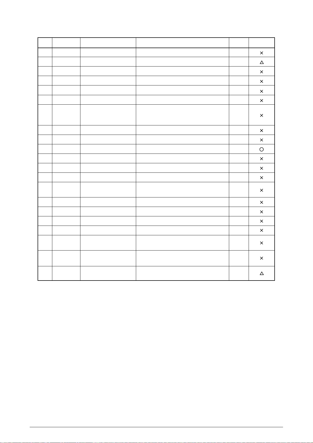
(2) How to start
NO.
1
All Letter & Rolling ASCII Continuous Print Test (Receipt)
2
All Letter & Rolling ASCII Continuous Print Test (Journal)
3
All Letter & Rolling ASCII Continuous Print Test (Receipt+Journal)
4
All Letter & Rolling ASCII Continuous Print Test (Slip)/(Sprocket)
5
Sample Data Continuous Print Test (Validation)
6
Menu (Receipt)
7
HEX Dump (Receipt)
8
MICR Read Test (Receipt)
9
Platen Maintenance Mode
10
Rewinder Rewind Evaluation Continuous Print Test (Journal)
Note 1
Note 2
Note 3
Note 4
Note 5
Note 6
Note 7
To enter the above modes, turn the power on while holding down the switches marked with
a circle ( ).
In No.4, if the lever is on the tractor side, the Sprocket Print Test becomes effective. If the
lever is not on the tractor side, the Slip Print Test becomes effective.
In Nos. 5, 8 and 10, if the lever is on the tractor side, these local functions become invalid,
and the printer starts in normal mode.
Nos.1 ~ 3, 6, 7 and 9 become effective regardless of the lever state.
In Nos.1~ 3, the print widths will be those set in the menu “Width of Roll Paper”.
In Nos.1 ~ 4 and 10, if SW1 is pressed, printing suspends. When the SW1 is pressed again,
the printing resumes.
In No.1 ~ 5, 8 and 10, if the cover is opened, printing suspends. When the cover is closed,
printing resumes.
(This is limited to only with the setting of Menu "Cover Open Alarm = YES", suspend in the
cases of No.6 and 7.)
In each local function, if the tractor lever is switched, Media Does Not Match Alarm (1) will
result. When the tractor is returned to the original position, the alarm is cleared and test
printing resumes.
Local Functions
SW 2 SW 3 SW 1 SW 4
41049421PS Rev.3 12 /
Page 13

2.3 LOCAL TEST
This function creates test data internally as if the printer received the data from the host, and prints
the test pattern.
2.3.1 Printer Status in Local Test Mode
When the local test begins, the printer cannot receive data (*1).
Even when a recoverable alarm occurs, the test mode is not cleared, and the test print resumes
when the alarm element is cleared.
The condition to end the local test is to turn the power off, but the local test is terminated when
I- PRIME signal (Parallel model) /Reset signal (Serial model) is received or a fatal alarm occurs.
(*1) When the printer cannot receive data, each I/F presents Busy as follows.
* Parallel model (Centronics interface): Busy signal → High
* Serial model (RS232C I/F): Busy control as follows.
When handshake is DTR/DSR: DTR signal → MARK status
When handshake is XON/XOFF: Sends DC3
2.3.2 Details of Local Test Prints
2.3.2.1 All Letter and Rolling ASCII Continuous Print Test (Receipt)
This function performs All Letter Print and Rolling ASCII Continuous Print in Receive mode.
It can test Auto Cutter Unit as well, and executes Auto Cut operations. It executes Auto Cut operation
only when “Auto Cutter Unit = Yes” is sent in the menu, however.
* In case of 1-Roll Model, since this model does not come with Auto Cutter Unit, the Auto Cut
function is invalid.
(1) How to start
Turn the power on while holding down the SW1.
(2) How to exit this mode
Turn the power off.
* During test printing, if you press SW1, printing suspends. If you press the SW1 again,
printing resumes.
(3) Printed contents and operations
(a) Auto Cut (Full Cut) operation
(b) Horizontal line (bit image print) printing
(c) Pattern (“ ”) printing to check breakage of the head pins
(d) Local test header printing
(e) UTL and HSD characters (20H~FFH) All Letter Print
(f) Auto Cut (Partial Cut) operation
(g) UTL characters (20H~7EH) Rolling ASCII Continuous Print
41049421PS Rev.3 13 /
Page 14

2.3.2.2 All Letter and Rolling ASCII Continuous Print Test (Journal)
This function performs All Letter Print and Rolling ASCII Continuous Print in Journal mode.
* In case of 1-Roll Model, this function is invalid.
(1) How to start
Turn the power on while holding down the SW4.
(2) How to exit this mode
Turn the power off.
* During test printing, if you press SW1, printing suspends. If you press the SW1 again,
printing resumes.
(3) Printed contents
(a) Horizontal lines (bit image print) printing
(b) Pattern (“ ”) printing to check breakage of the head pins
(c) Local test header printing
(d) UTL and HSD characters (20H~FFH) All Letter Print
(e) UTL characters (20H~7EH) Rolling ASCII Continuous Print
2.3.2.3 All Letter and Rolling ASCII Continuous Print Test (Receipt + Journal)
This function performs All Letter Print and Rolling ASCII Continuous Print in the Receipt+Journal
mode.
Prints the same data on both receipt and journal.
This function can test the auto cutter unit as well, and executes Auto Cut operation of receipts only
when “Auto Cutter Unit = Yes” is set in the menu, however.
* In case of 1-Roll Model, this function is invalid.
(1) How to start
Turn the power on while holding down SW1 + SW4.
(2) How to exit this mode
Turn the power off.
* During test printing, if you press SW1, printing suspends. If you press the SW1 again,
printing resumes.
(3) Print contents and operations
(a) Auto Cut (Full Cut) operation
(b) Horizontal line (bit image print) printing
(c) Pattern (“ ”) printing to check breakage of the head pins
(d) Local test header printing
(e) UTL and HSD characters (20H~FFH) All Letter Print
(f) Auto Cut (Partial Cut) operation
(g) UTL characters (20H~7EH) Rolling ASCII Continuous Print
41049421PS Rev.3 14 /
Page 15

2.3.2.4 All Letter and Rolling ASCII Continuous Print Test (Slip/Sprocket)
This function performs Rolling ASCII Continuous Print after All Letter Print.
(1) How to start
Turn the power on while holding down the SW2. If the lever is on the tractor side, the Sprocket
paper print test takes place. Otherwise, Slip paper print test takes place.
(2) How to exit
Turn the power off.
* During test printing, if you press SW1, printing suspends. If you press the SW1 again,
printing resumes.
(3) Print contents
(a) Horizontal line (bit image print) printing
(b) Pattern (“ ”) printing to check breakage of the head pins
(c) Local test header printing
(d) UTL and HSD characters (20H~FFH) All Letter Print
(e) UTL and HSD characters (20H~FFH) All Letter Print in Compressed Mode.
(f) UTL characters (20H~7EH) Rolling ASCII Continuous Print
2.3.2.5 Sample Data Continuous Print Test (Validation)
This function performs the test print on the Validation paper.
(1) How to start
Turn the power on while holding down the SW3.
(2) How to exit
Turn the power off.
(3) Print contents
(a) UTL character (20H~86H) printing (prints only one-line)
* Prints one-line when Validation is inserted, then enters Waiting for Removal state. After
the validation is removed, the printer enters the Waiting for Insertion state. Repeat the
sequence : Set paper → Print → Remove.
41049421PS Rev.3 15 /
Page 16

2.3.2.6 MICR Read Test (Receipt)
This function performs MICR read and prints that result on the receipt paper.
Effective only when the MICR unit is installed and “MICR Unit = Yes(CMC-7)” or “MICR Unit = Yes(E13B)” is set in the menu.
(1) How to start
Turn the power on while holding down SW2 + SW3.
(2) How to exit
Turn the power off.
(3) Contents of the test
(a) When this mode is started, the printer enters Wait for MICR Insertion state.
(b) Insert MICR card and perform MICR read.
(c) The printer prints MICR read results on the Receipt paper, and enters Wait for MICR
Insertion state.
(b) and (c) above are repeated.
(4) Contents printed
<When Read is OK:>
(a) Prints “Read OK”.
(b) Prints the MICR read results in HEX dump.
(“XX XX ...... XX” + ASCII: 1 line contains 8 byte information)
<When Read is NG:>
(a) Prints “Read NG”.
(b) Prints the MICR read results (Return Code (1 byte) and read data) in HEX dump.
(“XX XX ...... XX” + ASCII: 1 line contains 8 byte information)
* Regarding MICR Read result, Return Code (1 byte) and Read Data are printed.
When the Return Code is 30H (“No errors”), it is assumed as “Read OK” Otherwise, it
is assumed as “Read NG”
* Return codes are shown below:
Return code Status
30H (0) No errors.
33H (3) Error: Read/Decode error.
34H (4) Error: No magnetic ink detected.
36H (6) Error: Document jam or document is too long.
41049421PS Rev.3 16 /
Page 17
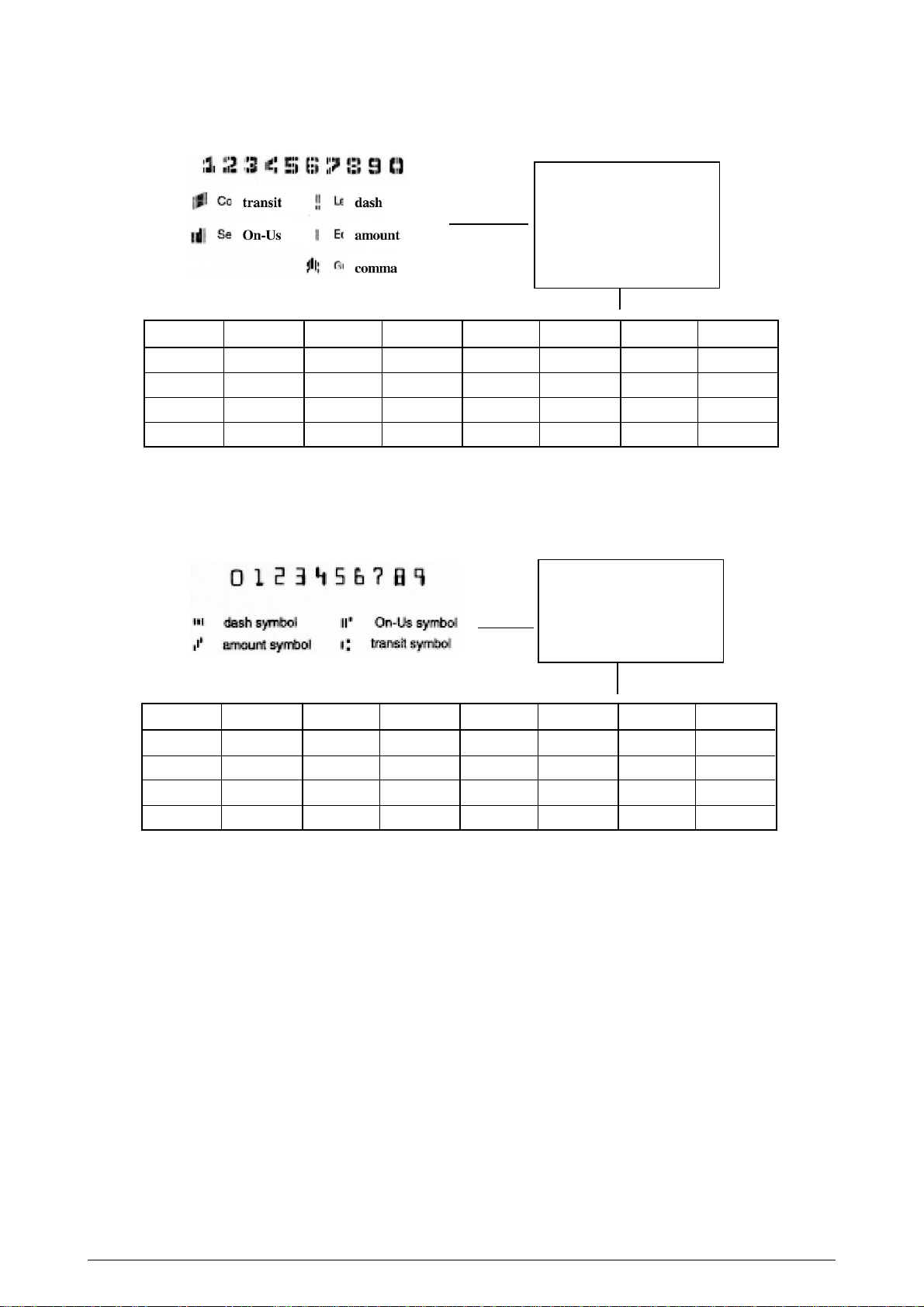
* When character set is CMC-7, the below codes are returned.
A: dash symbol
B: amount symbol
C: transit symbol
D: On-Us symbol
E: comma symbol
Character Code Character Code Character Code Character Code
1 31H 2 32H 3 33H 4 34H
5 35H 6 36H 7 37H 8 38H
9 39H 0 30H (space) 20H A 41H
B 42H C 43H D 44H E 45H
* Unknown:3FH(?)
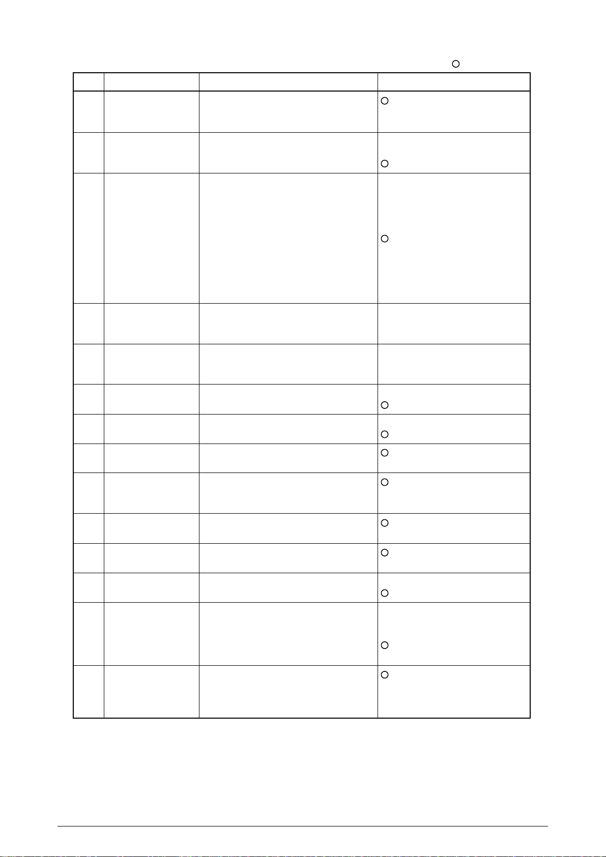
* When character set is E-13B, the below codes are returned.
A: dash symbol
B: amount symbol
C: transit symbol
D: On-Us symbol
Character Code Character Code Character Code Character Code
1 31H 2 32H 3 33H 4 34H
5 35H 6 36H 7 37H 8 38H
9 39H 0 30H (space) 20H - -
A 41H B 42H C 43H D 44H
* Unknown:3FH(?)
(Note)
In both cases of CMC-7 and E-13B, special character codes are different from those sent
to host by a check paper read command.
2.3.2.7 Rewinder Winding Evaluation Continuous Print Test (Journal)
This function performs print/platen switch continuous test to evaluate the rewinder winding
performance.
* In case of 1-Roll Model, this function will be in Roll Paper mode.
(1) How to start
Turn the power on while holding down SW3 + SW1 + SW4.
(2) How to exit
Turn the power off.
* During test printing, if you press the SW1, printing suspends. If you press the SW1 again,
printing resumes.
(3) Contents printed
(a) Prints “HHH”+ Space + “HHH” (UTL characters)
(b) Print Sheet Mode switching (Journal → Slip → Journal)
41049421PS Rev.3 17 /
Page 18

2.3.3 Local Test Header
Prints Model Name, Design Drawing Number, Version and F/W Revision.
OKIPOS 425D 41783801YR *1
VER 01 F/W REV 01.00
*1 1-Roll model: OKIPOS 425S 41783701YR
2-Roll model: OKIPOS 425D 41783801YR
The device names are not finalized yet.
The above names are tentative.
41049421PS Rev.3 18 /
Page 19

2.4 MENU FUNCTION (Receipt)
2.4.1 Overview
The menu function is the local function that sets each mode to control the printer and adjusts it. This
mode has the following items, saved in the E2P-ROM. This information is printed only when the
menu mode is activated at Power On, and the information can be written over from the operator
panel.
Menu Print is printed in Receipt Mode.
For the printer’s initialization state, each mode is set according to the information of this area.
2.4.2 Menu Items
(1) Auto Cutter Unit
(2) MICR Unit
(3) Print Registration
(4) Top Adjust
(5) Cut Adjust
(6) Auto LF (Auto line feed)
(7) Receive Buffer Size
(8) Print Mode
(9) Off-line Busy Control
(10) Cover Open Alarm
(11) Width of Roll Paper
(12) Zero Character
(13) Page Lengths
(14) Page End Signal
41049421PS Rev.3 19 /
Page 20
Default Value
NO.
1
Auto Cutter Unit
2
MICR Unit
3
Print Registration
4
Top Adjust
5
Cut Adjust
Item
Function
Selects Auto Cutter Unit Installed/Not
Installed.
Selects MICR Unit Installed/Not Installed.
Adjusts the print position if it shifts in
Forward printing and Reverse printing.
Adjusts Top Of Form position when
Slip/Sprocket are used.
Adjusts Cut Position when cutting
Sprocket paper.
Sets
Yes
No
*Default of 1-Roll Model is No.
Yes(CMC-7)
Yes(E-13B)
No
0.25mm Right
0.20mm Right
0.15mm Right
0.10mm Right
0.05mm Right
0
0.05mm Left
0.10mm Left
0.15mm Left
0.20mm Left
0.25mm Left
-1.75mm ~ +1.75mm
* Can be set in the 0.35mm unit.
* Default value : 0 mm
-1.75mm ~ +1.75mm
* Can be set in the 0.35mm unit.
* Default value : 0 mm
6
Auto LF
(Auto line feed)
7
Receive Buffer Size
8
Print Mode
9
Off-line Busy Control
10
Cover Open Alarm
11
Width of Roll Paper
12
Zero Character
13
Page Length
14
Paper End Signal
Selects auto line feed.
(Selects auto line feed by CR Code)
Selects Receive Buffer Size
Selects font
Selects conditions of BUSY
Selects enable/disable of print stop in
Cover Open
Selects the paper width of Roll paper
(Changes the print area.)
Selects a zero font
Selects the paper length of Sprocket
paper.
Selects the paper sensor that enables
Paper End signal.
* RNE :
Receipt/Journal Near End Sensor
* RE : Receipt/Journal End Sensor
Yes
No
2K
16K
Utility
HSD
Yes * Off-line or Receive buff-
er-full
No * Receive buffer-full
Yes
No
76.2mm
69.5mm
Slashed
Unslashed
88.9mm
139.7mm
215.9mm
279.4mm
304.8mm
Yes (RNE or RE)
Yes (RE)
No
Note 1)
Note 2)
In the 1-Roll Model, an auto cutter unit cannot be installed.
I/F control information (baud rate and etc.) and customer display connection/disconnec-
tion of serial model are set by DIP-SW of the I/F board.
Note 3)
MICR Unit selection has the following two types for MICR Read test (Refer to Section
2.3.2.6.): “Yes (CMC-7),” and “Yes (E-13B)” Normally, either selection is recognized as
an actual installation status of MICR Unit, and MICR type is selected by designation of the
command.
41049421PS Rev.3 20 /
Page 21
2.4.3 How to Operate
2.4.3.1 Start
To start the Menu Mode, turn the printer on while holding down SW2 + SW1. When the printer’s
initialization ends correctly, the printer prints the title “Menu Print” and all the menu items and set
values. Then, the printer line-feeds until the print result goes beyond the Manual Cutter position,
prints the item/set value immediately after “Menu Print”, then, waits for a switch to be pressed.
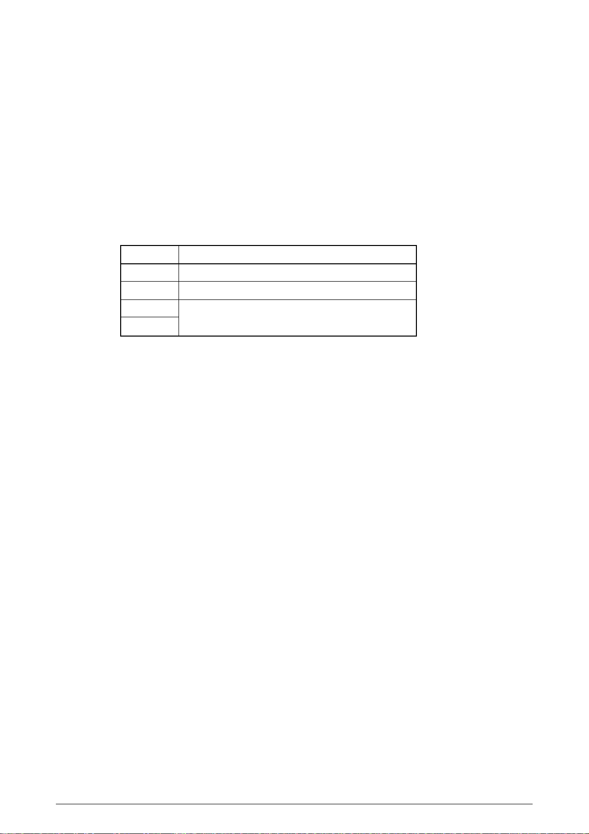
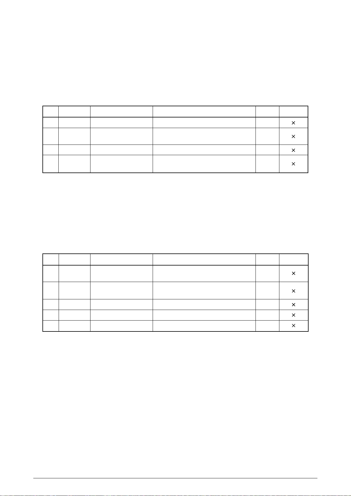
2.4.3.2 Operation
The switch functions during the menu mode are as follows:
Switch
SW2
SW3
SW1
SW4
Function
Advances the set values of the Menu Item, one at a time.
From the last set value, returns to the first set value.
Ends Menu Mode.
Registers the set values in EEPROM, then, prints the end
message “Menu End” and returns to the same initialized
state as at power on.
Advances the Menu Items, one at a time.
From the last Menu Item, returns to the first Menu Item.
Feeds the receipt, by one line.
41049421PS Rev.3 21 /
Page 22

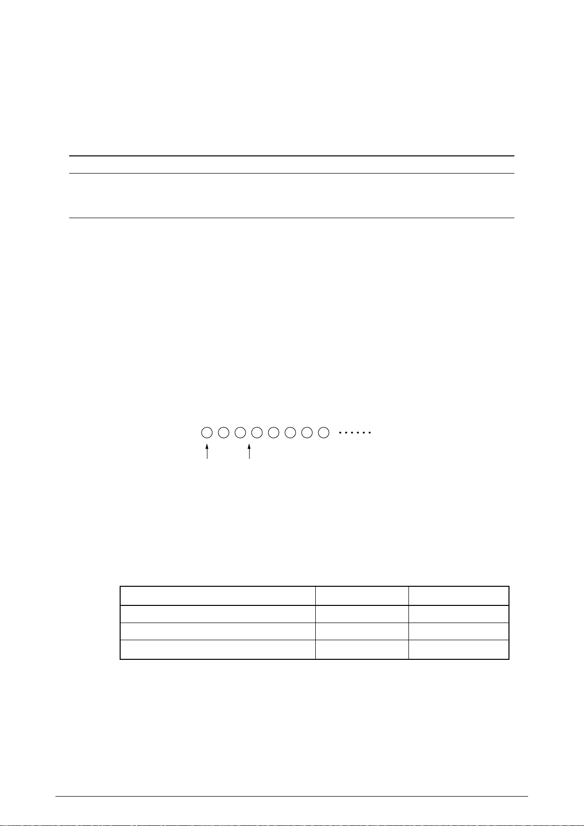
2.5 HEX DUMP FUNCTION (Receipt)
This function converts received data, as it is, to character codes, and prints it in the Receipt mode.
The printed contents are as follows: Upon receiving one byte, the printer divides it into three
characters, High-nibble, Low-nibble and a space. Regarding these as 1 block, the printer prints 8
blocks in one line, then, prints the same data in the character format.
Upon entering the HEX dump mode, the printer prints “Hex Data Dump”. (Title printing)
2.5.1 Print Format
Hex Data Dump
0000 XX XX XX XX XX XX XX XX : ........
0008 XX XX XX XX XX XX XX XX : ........
.
.
.
.
FFF8 XX XX XX XX XX XX XX XX : ........
0000 XX XX XX XX XX XX XX XX : ........
.
.
.
.
Hex dataLine No. ASCII data
2.5.2 How to Print
(1) If it does not receive data after 150ms have passed since receiving last data, the printer starts
printing (CR) if it has some data.
(If there is not enough data to form 8 blocks, spaces will be used.)
If it subsequently receives data, the printer prints from a position next to the position at which
the printing started.
(2) If it receives the I-PRIME signal (Parallel model)/Reset signal (Serial model), the printer starts
printing if it has some data, then, feeds one line. Then, the printer is initialized. (If it does not
have any data, the printer feeds one line and then, is initialized.) After the initialization, the
printer starts up in dump mode again and prints. The line number is reset, however, and
counting begins from “0000”.
* When I-PRIME signal (Parallel model)/Reset signal (Serial model) is hard reset (setting by
Short Plug with Parallel I/F board and by DIP SW with Serial I/F board), it immediately starts
initialization and does not continue hex dump.
(3) One line-feed is added for every 16 lines.
(4) The count begins from “0000” when the line number exceeds “FFF8”.
41049421PS Rev.3 22 /
Page 23
2.6 PLATEN MAINTENANCE MODE
This function is for switching the platen position when the print head gap is adjusted in the production
line.
(1) How to start the mode
Turn the power on while holding down SW2 + SW3 + SW1.
*1 This mode can be executed even when the print head is not installed.
*2 When this mode is being started, the initial platen position should be on the Receipt side.
If the paper is already loaded in the Tractor mode, the platen should be on the Slip side.
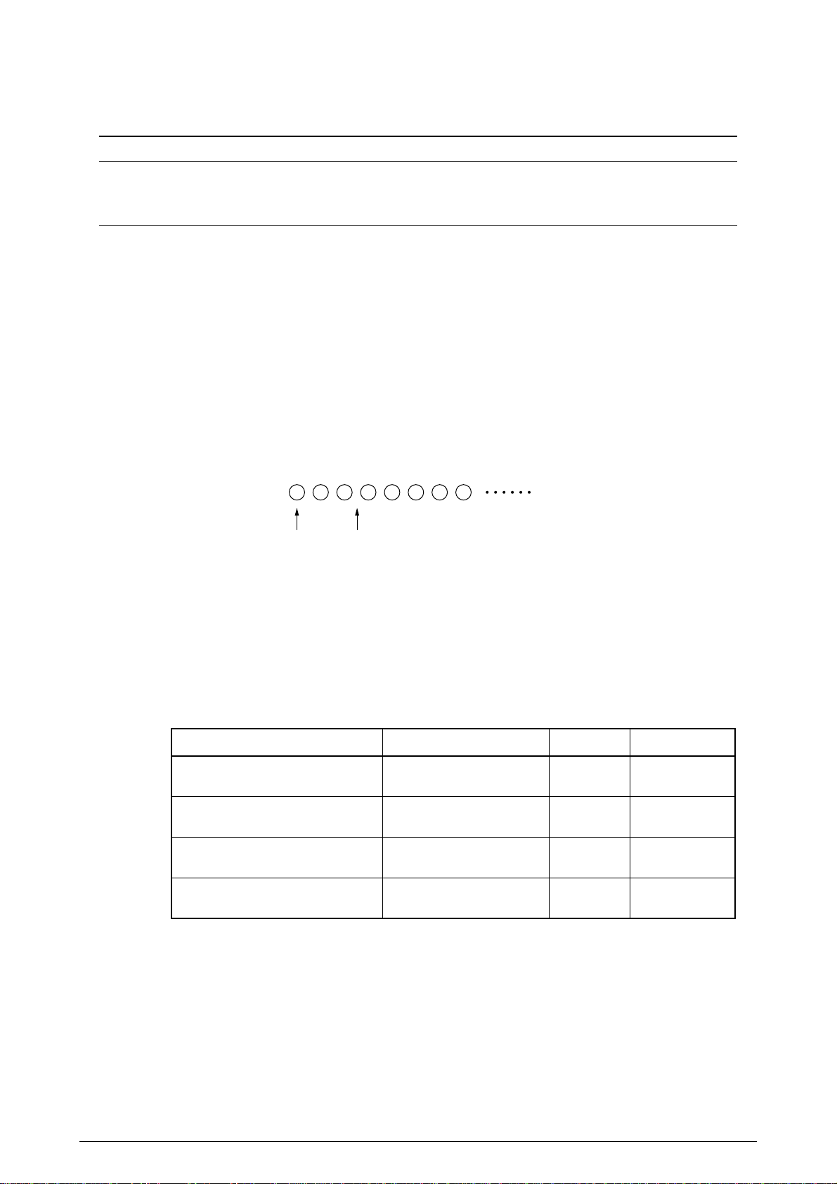
(2) How to operate
Switch
SW2
SW3
SW1
SW4
(3) How to exit the maintenance mode
Turn the power off.
Moves the platen to the Receipt side.
Moves the platen to the Slip side.
Invalid
Function
41049421PS Rev.3 23 /
Page 24
3. COMMAND DESCRIPTION
The intent of this document is to describe the details of the command functions that are effectuated
by the firmware.
3.1 Control Code
3.1.1 Control Code List
3.1.1.1 Function Code
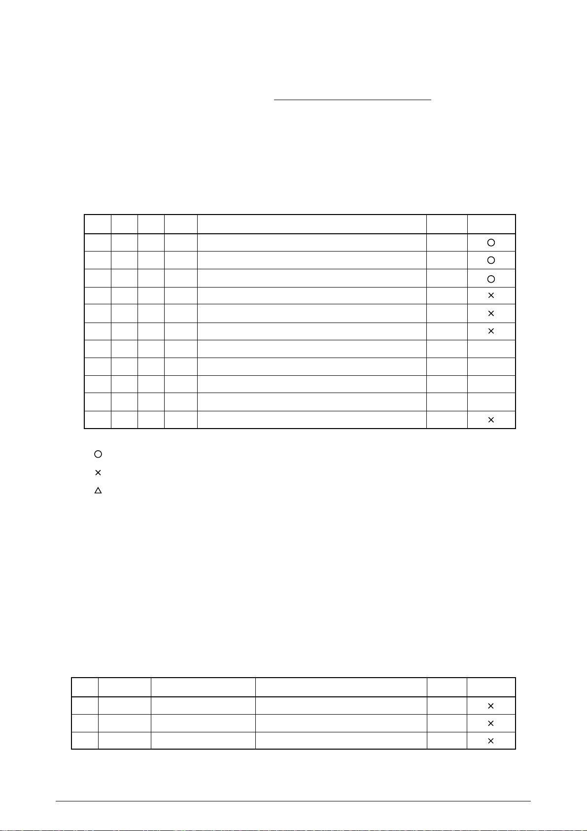
(1) List of Function Codes
No.
HEX
DEC
CODE
1
0A
10
LF
Print/line feed
2
0C
12
FF
Eject Cut Sheet paper or form-feed sprocket paper
3
0D
13
CR
Print/carriage return
4
0F
15
5
12
18
6
18
24
7
10
16
SI
Condense Designate
DC2
Condense Clear
CAN
Cancel print data
DLE
Start DLE sequence
Remarks
Section
3.2.3.1
3.2.3.7
3.2.1.1
3.2.5.10
3.2.5.12
3.2.8.4
3.1.1.2
Print Start
–
8
1B
27
9
1C
28
10
1D
29
11
1E
30
* Print Start Column
: Command that invokes print start
: Command that does not invoke print start
: Command that sometimes invokes print start
(This applies hereafter.)
3.1.1.2 DLE Sequence
(1) Command recognition
A code that follows a DLE code is treated as a 7-bit code. (MSB=0)
For the parameters, which vary among the commands, see each command’s functions.
If a function code follows a DLE code, it is is treated as a stand-alone function code.
If DLE codes come in succession, they are treated as a DLE code.
Example: DLE DLE EOT n is treated as command DLE EOT n.
ESC
Start ESC sequence
FS
Start FS sequence
GS
Start GS sequence
RS
Journal T ab
3.1.1.3
3.1.1.4
3.1.1.5
3.2.2.5
–
–
–
(2) DLE sequences
No.
1
2
3
41049421PS Rev.3 24 /
HEX
10 04
10 04 08
10 05
Command Sequence
DLE EOT n
DLE EOT BS n
DLE ENQ n
Functions
Real-time status sending
Real-time MICR status sending
Real-time request to Printer
Print StartSection
3.2.8.16
3.2.8.18
3.2.8.17
Page 25
3.1.1.3 ESC Sequence
(1) Command recognition
For the handling of codes that follow the ESC Code, when the ESC codes come in succession,
and their relationship with the functional codes, the way the DLE sequence is handled applies.
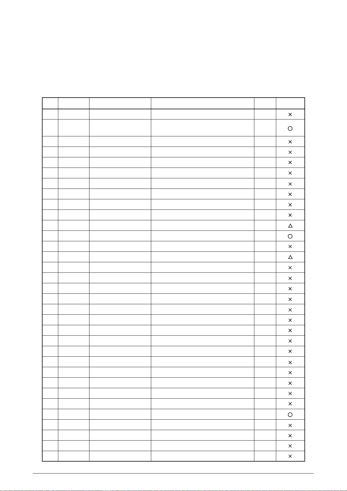
(2) ESC sequence list
No.
1
2
3
4
5
6
7
8
9
10
11
12
13
14
15
HEX
1B 0F
1B 10 44
1B 10 61
1B 10 63
1B 10 63
1B 10 6C
1B 10 72
1B 10 76
1B 20
1B 21
1B 24
1B 25 35
1B 25 39
1B 2A
1B 2D
Command Sequence
ESC SI
ESC DLE D
Pno Pa1 Pb1...Pan Pbn
ESC DLE a Pno n
ESC DLE c Pno 0 n
ESC DLE c Pno 1 n
ESC DLE l Pno n1 n2
ESC DLE r Pno n
ESC DLE v Pno n
ESC SP n
ESC ! n
ESC $ n1 n2
ESC % 5 n
ESC % 9 n
ESC * m n1 n2 data
ESC - n
Functions
Condense Designate
Sets up menu items
Enables/disables auto status send
Selects print sheet
Selects set sheet
Sets Left Margin
Real-time status sending
Selects Validation insert position
Sets chracter right-side space
Designates Print Mode all at once
Designates absolute position
Feeds paper in inrements of n/144"
Sets n/144" line feed
Designates Bit Image Mode
Designates/clears Underline
Print StartSection
3.2.5.11
3.2.8.9
3.2.8.24
3.2.7.9
3.2.7.10
3.2.2.1
3.2.8.25
3.2.8.23
3.2.5.1
3.2.5.9
3.2.2.2
3.2.3.13
3.2.3.14
3.2.6.1
3.2.5.2
16
17
18
19
20
21
22
23
24
25
26
27
28
29
30
31
32
1B 30
1B 31
1B 32
1B 33
1B 34
1B 35
1B 3C
1B 3D
1B 40
1B 41
1B 43
1B 45
1B 47
1B 4A
1B 4E
1B 4F
1B 52
ESC 0
ESC 1
ESC 2
ESC 3 n
ESC 4
ESC 5
ESC <
ESC = n
ESC @
ESC A n
ESC C n
ESC E n
ESC G n
ESC J n
ESC N n
ESC O
ESC R n
Sets 1/8" line feed
Sets 7/72" line feed
Sets 1/6" line feed
Sets n/144" line feed
Sets Italic Mode
Resets Italic Mode
Designates one-line uni-directional print
Selects peripheral device
Initializes printer
Sets n/72" line feed pitch
Sets page length for Sprocket paper
Designates/cancels Emphaize print
Designates/cancels Double Strike print
Feeds paper in increments of n/144"
Sets Sprocket paper performation skip
Resets Sprocket paper perforation skip
Selects international character set
3.2.3.2
3.2.3.3
3.2.3.4
3.2.3.5
3.2.5.5
3.2.5.6
3.2.8.7
3.2.8.1
3.2.8.5
3.2.3.6
3.2.3.8
3.2.5.7
3.2.5.8
3.2.3.11
3.2.3.9
3.2.3.10
3.2.4.1
33
1B 55
41049421PS Rev.3 25 /
ESC U n
Designates/cancels uni-directional print
3.2.8.6
Page 26
No.
HEX
Command Sequence
Functions
Print StartSection
34
35
36
37
38
39
40
41
42
43
44
45
46
47
48
1B 57
1B 5C
1B 5E
1B 61
1B 63 30
1B 63 31
1B 63 32
1B 63 34
1B 63 35
1B 64
1B 66
1B 69
1B 6D
1B 70
1B 74
ESC w n
ESC \ n1 n2
ESC ^ m n1 n2
ESC a n
ESC c 0 n
ESC c 1 n
ESC c 3 n
ESC c 4 n
ESC c 5 n
ESC d n
ESC f t1 t2
ESC i
ESC m
ESC p m t1 t2
ESC t n
Designates/cancels double width print
Desigantes relative position
Desigantes 9-pin Bit Image Mode
Aligns positions
Selects print sheet
Selects set sheet
Selects paper sensor that enables the
paper end signal; valid only with Parallel I/F
Selects print stop sensor
Enables/disables panel switch
Feeds paper for n lines
Sets Cut paper wait time
Full cut
Partial cut (keeping one point uncut)
Generaes designated pulse (Open
Cash Drawer)
Selects character code table
3.2.5.4
3.2.2.3
3.2.6.2
3.2.2.4
3.2.7.1
3.2.7.2
3.2.7.3
3.2.7.4
3.2.8.3
3.2.3.12
3.2.7.5
3.2.7.6
3.2.7.7
3.2.8.11
3.2.4.2
49
50
51
52
53
54
1B 75
1B 76
1B 77
1B 7A
ESC u n
ESC v
ESC w n
ESC z n
Sends perupheral device status
Sends paper sensor status
Sets/resets Double Height print
Designates/cancels Receipt+Journal
3.2.8.2
3.2.8.8
3.2.5.3
3.2.7.8
same data print
1B 10 41
ESC DLE A Pno N1...N8
Selects and sets the barcode type and
3.2.9.1
size
1B 10 42
ESC DLE B Pno Pm
Prints barcode data
3.2.9.2
DATA
* The ESC DLE sequence other than No. 2~8, 53, 54 will be ignored by the sequence.
(The data that follows “Pno” will be ignored as many bytes as set by Pno.)
41049421PS Rev.3 26 /
Page 27
3.1.1.4 FS Sequence
(1) Command recognition
For the handling of subsequent codes that follow the FS code, when the FS codes come in
succession, and their relationship with the functional codes, the way the DLE sequence is
handled applies.
(2) FS Sequence table
No.
1
2
3
4
HEX
1C 61 30
1C 61 31
1C 61 32
1C 62
Command Sequence
FS a 0 n
FS a 1
FS a 2
FS b
3.1.1.5 GS Sequence
(1) Command recognition
For the handling of subsequent codes that follow the GS code, when the GS codes come in
succession, and their relationship with the functional codes, the way the DLE sequence is
handled applies.
(2) GS Sequence table
No.
1
HEX
1D 05
Command Sequence
GS ENQ
Functions
Reads Check paper
Loads Check paper to the print start
position
Ejects Check paper
Requests for resending a result of
reading Check paper
Functions
Sends a status of the pritner status
real-time
Print StartSection
3.2.8.19
3.2.8.20
3.2.8.21
3.2.8.22
Print StartSection
3.2.8.13
2
3
4
5
1D 45
1D 49
1D 61
1D 72
GS E n
GS I n
GS a n
GS r n
Selects print speed and printhead
current flow time
Sends a prionter ID
Enables/disables auto status send
Sends a status
3.2.8.10
3.2.8.14
3.2.8.12
3.2.8.15
41049421PS Rev.3 27 /
Page 28

3.2 Control Operations
The control functions are described in the subsequent sections.
3.2.1 Print Operation Control
This section describes the print operation control functions.
3.2.1.1 Print/Carriage Return
Name: Print/Carriage Return
HEX: 0DH
Code
DEC: 13
Functions:
(1) To start printing received data and set the position to start receiving the next line’s data at the
left margin position (start of that line) after printing.
(2) To perform Carriage Return and Line Feed if Auto LF is set to Enabled on the menu.
(3) To perform Carriage Return to the start position of the line on Receipt side in Receipt+Journal
mode.
(4) To prompt the mode to shift Receipt+Journal in Validation Mode if Auto LF is set to Enabled
on the menu.
CR
41049421PS Rev.3 28 /
Page 29
3.2.2 Space Control
The space control functions are described in the subsequent sections.
3.2.2.1 Left Margin Set
ESC DLE l Pno n1 n2
Name: Setting Left Margin
HEX: 1BH 10H 6CH Pno n1 n2
Code
DEC: 27 16 108 Pno n1 n2
Function:
(1) To set Left Margin in increments of 1/60" from the home position.
n1= low-order bytes and n2=high-order bytes
(2) The DEL in the command sequence disables MSB. (“90H” is effective as well.)
(3) Valid range and definitions of parameters
(a) Pno: To designate the number of bytes (number of parameters) following ESC DLE
l Pno MSB is invalid.
Range: 00H ≤ Pno ≤ FFH
With this command, Pno=2.
(b) To designate the print position by n1 n2 on the basis of the home position.
Example) In case of ESC DLE l 02H 02H 00H:
n1=02H
n2=00H
The print position would be:
Home Position "0" Left Margin (increments of 1/60")
In this case, Left Margin is 2/60" from the home position.
(4) Range and definitions of n1,n2
0(00H) ≤ n1 ≤ 255 (FFH)
0(00H) ≤ n2 ≤ 255 (FFH)
If a value exceeding the value below is set, this command will be ignored and the previous
setting will remain valid.
The maximum value of n1, n2 would be one that does not fall below 1.25" in the distance to
the right margin.
Selected print sheet
Receipt/Journal/Receipt+Journal(76.2mm)
Receipt/Journal/Receipt+Journal(69.5mm)
Slip(/MICR Read)/Sprocket paper (option)
Range of n1, n2
0 ≤ n2 n1 ≤ 93
0 ≤ n2 n1 ≤ 77
0 ≤ n2 n1 ≤ 303
Right Margin (")
2.8
2.53
6.3
(5) Received within the line, this command will be ignored.
(6) If setting is made by this command in Receipt/Journal/Receipt+Journal Mode, that setting will
be valid for both Receipt and Journal.
It will not affect Slip/Validation/Sprocket.
(7) If setting is made by this command in Slip/Validation/Sprocket Mode, that setting will be valid
for all of Slip/Validation/Sprocket.
It will not affect Receipt or Journal.
(8) Neither the left margin position that is set in Receipt/Journal/Receipt+Journal Mode nor the left
margin position set in Slip/Validation/Sprocket Mode will change when the mode is switched.
41049421PS Rev.3 29 /
Page 30
3.2.2.2 Absolute Position Designate
ESC $ n1 n2
Name: Absolute Position Designate
HEX: 1BH 24H n1 n2
Code
DEC: 27 36 n1 n2
Function:
(1) To move a next printing position from the start position in the line to the one designated by n1
n2 in increments of 1/180" or 1/240".
Default unit of measurement is 1/180", but 1/240" if Condense is set.
n1 = low-order byte, n2 = high-order byte
(2) To designate the print position according to n1 n2, based on the left margin position (start
position of the line).
The left margin changes, the print start position, too, changes even if the setting is the same.
e.g.) ESC $ 02H 00H
n1 = 02H
n2 = 00H
The print position would be:
Left Margin Print Position (increments of 1/180 or 1/240")
In this case, subsequent data will be printed 2/180" or 2/240" from the left margin.
(3) Valid range and definitions of n1,n2
0(00H) ≤ n1 ≤ 255(FFH)
0(00H) ≤ n2 ≤ 255(FFH)
(4) Range of n1 n2 (If any value outside the range is designated, the command will be ignored in
its entirety.)
The range in the table below assumes the left margin position being 0.
If Left Margin + Absolute Position exceeds the right margin (ininches) in the table below, the
command will be ignored in its entirety.
Selected print sheet
Receipt/Journal/Receipt+Journal
(76.2mm)
Receipt/Journal/Receipt+Journal
(69.5mm)
Slip/Validation
Sprocket (option)
Range of n1 n2
0 ≤ n2 n1 ≤ 504 (1/180")
0 ≤ n2 n1 ≤ 672 (2/240")
0 ≤ n2 n1 ≤ 456 (1/180")
0 ≤ n2 n1 ≤ 608 (2/240")
0 ≤ n2 n1 ≤ 1134 (1/180")
0 ≤ n2 n1 ≤ 1512 (2/240")
0 ≤ n2 n1 ≤ 1134 (1/180")
0 ≤ n2 n1 ≤ 1512 (2/240")
Margin
504/180"
672/240"
456/180"
608/240"
1134/180"
1512/240"
1134/180"
1512/240"
Right Margin (")
2.8
2.53
6.3
6.3
(5) The amount of movement is calculated according to the following formula.
Movement (Distance from left margin) = {n1+(n2 AND 03H) × 256}/180 (inch) or
= {n1+(n2 AND 03H) × 256}/240 (inch)
0 ≤ movement < 6.3 (inch)
(6) If the parameter (n1 n2), which would set the print position to the left of the present print position,
is designated, print start is prompted.
(7) No underline is added to the movement made by this command.
(8) When Same Data Print is reset with Receipt+Journal, if the present position is located on the
Receipt side, the setting within the Receipt print position is valid, and if the present position is
located on the Journal side, the setting within the Journal print range is valid.
(On the Journal side, the left edge of the Journal print area is set as a start position of the pint line.)
41049421PS Rev.3 30 /
Page 31

3.2.2.3 Relative Position Designate
ESC \ n1 n2
Name: Relative Position Designate
HEX: 1BH 5CH n1 n2
Code
DEC: 27 92 n1 n2
Function:
(1) To move a next print position to the right or to the left, relative to the present position.
To move the print position to the position designated by n1 n2 in increments of 1/180" or 1/240".
Default unit is 1/180" but 1/240" if Condense is set.
n1 = low-order byte, n2 = high-order byte
(2) To designate the print position to left/right by the dots as designated by n1 n2, on the basis of
the present position being “0.”
Ex.) In case ESC \ 02H 00H is received:
n1=02H
n2=00H
Thus, the print position would be
1/180" or 1/240"
Present Position Print Position
(3) A pair of n1 n2 consists of 2 bytes making up a 16-bit numerical value.
Its 16th bit indicates a code. {positive = right, negative (Two’s complement)=left}
n1
LSB
15 14 13 12 11 10 9 8
MSB
0: Right
Code bit
1: Left
n2
bb
b b
7 6 5 4 3 2 1 0
41049421PS Rev.3 31 /
Page 32

(4) Range of move
Direction
Forward
Selected Print
Sheet
Receipt/Journal
(76.2mm)
Receipt/Journal
(69.5mm)
Slip/Validation
Sprocket
(option)
Reverse
Receipt/Journal
(76.2mm)
Receipt/Journal
(69.5mm)
Slip/Validation
Sprocket
(option)
(5) Maximum value of n2 n1
Range of n1 n2
0H ≤ n2 n1 ≤ 504-(present Position) (1/180")
0H ≤ n2 n1 ≤ 672-(present Position) (1/240")
0H ≤ n2 n1 ≤ 456-(present position) (1/180")
0H ≤ n2 n1 ≤ 608-(present position) (1/240")
0 ≤ n2 n1 ≤ 1134-(present position) (1/180")
0 ≤ n2 n1 ≤ 1512-(present position) (1/240")
0 ≤ n2 n1 ≤ 1134-(present position) (1/180")
0 ≤ n2 n1 ≤ 1512-(present position) (1/240")
-(present position) ≤ n2 n1<0 (1/180")
-(present position) ≤ n2 n1<0 (1/240")
-(present position) ≤ n2 n1<0 (1/180")
-(present position) ≤ n2 n1<0 (1/240")
-(present position) ≤ n2 n1<0 (1/180")
-(present position) ≤ n2 n1<0 (1/240")
-(present position) ≤ n2 n1<0 (1/180")
-(present position) ≤ n2 n1<0 (1/240")
Right Margin
504/180"
672/240"
456/180"
608/240"
1134/180"
1512/240"
1134/180"
1512/240"
504/180"
672/240"
456/180"
608/240"
1134/180"
1512/240"
1134/180"
1512/240"
Right
Margin (")
2.8
2.53
6.3
6.3
2.8
2.53
6.3
6.3
Selected Print Sheet
Receipt/Journal (76.2mm)
Receipt/Journal (69.5mm)
Slip/Validation
Sprocket(option)
Maximum value for Forward
504/180"
672/240"
456/180"
608/240"
1134/180"
1512/240"
1134/180"
1512/240"
Maximum value for Reverse
-504/180"
-672/240"
-456/180"
-608/240"
-1134/180"
-1512/240"
-1134/180"
-1512/240"
(6) A move in Reverse will prompt print start.
(7) If a move outside the printable range is designated, the command is ignored in its entire
sequence.
(8) If Underline is designated with the move made by this command, no underline will be applied
to the skipped spaces.
(9) When Same Data Print is reset with Receipt+Journal, if the present position is located on the
Receipt side, the setting within the Receipt print position is valid, and if the present position is
located on the Journal side, the setting within the Journal print range is valid. (On the Journal
side, the left edge of the Journal print area is set as a start position of the line.)
(10) In Validation Mode, if this command is received when the present position is already beyond
the right margin, the command will be ignored in its entire sequence. (See 3.4.3 Right Margin
Process.)
41049421PS Rev.3 32 /
Page 33

3.2.2.4 Position Align
Name: Position Align
HEX: 1BH 61H n
Code
DEC: 27 97 n
Function:
(1) To align the print position
(2) Valid range and definitions of n
Mode Value of n Definition
0 00H, 30H Left alignment (Default)
1 01H, 31H Center alignment
2 02H, 32H Right alignment
(a) If n is any other value than the above, this command is ignored and the previously set mode
remains effective.
(b) This command is valid only when received at the start of the line. Received some-way into
the line, the command will be ignored.
(3) Mode 0 (Left alignment)
To align the print start position relative to the left margin.
(4) Mode 1 (Center alignment)
(a) Those characters that would go beyond the right margin will be aligned relative to the
center of a next line. (This includes spaces at the start and end of the line.)
(b) Even if character pitch is changed in the middle of the line (Normal, Enlarge, and Character
right-side space), an entire text will be spread over evenly.
(5) Mode 2 (Right alignment)
To align the printer end position relative to the right margin.
(6) To align image as well.
(7) To align absolute skip and relative slip as well.
ESC a n
3.2.2.5 Journal Tab
RS
Name: Journal Tab
HEX: 1EH
Code
DEC: 30
Function:
(1) To move the print position to the top of Journal.
(2) Valid only in Receipt+Journal Mode and if Same Data Print to Receipt/Journal has been reset.
(Invalid if the present horizontal position is on the Journal side.)
41049421PS Rev.3 33 /
Page 34

3.2.3 Line Feed Control
The line feed control functions are described in the subsequent sections.
3.2.3.1 Print/Line Feed
Name: Print/Line Feed
HEX: 0AH
Code
DEC: 10
Functions:
(1) To complete receiving data for a line and start printing. To perform one line-feed after printing
has ended, according to the amount of line feed set for each type of print sheet (Receipt,
Journal, Slip, or Sprockect paper (option)).
(To perform line feed for the amount in accordance with each set value in the Receipt+Journal
mode.)
(2) To perform carriage return after printing by this command has started. The position following
carriage return is at the left margin (start of the line).
(The position is at the left margin on the Receipt side with the Same Data Print is reset in
Receipt+Journal Mode.)
(3) To perform perforation skip to the next TOF position when the selected print sheet is Sprocket
(option) if the position following line feed is within the perforation skip area.
(4) To set the line feed pitch for each type of print sheet in a combination of designation by ESC
0, ESC 1, ESC 2, ESC 3 n, ESC A n, or ESC % 9 n and Sheet selection by ESC c 1 n, ESC
DLE c Pno 1 n.
(5) Default line feed is one sixth of an inch (1/6") for all types of print sheet.
(6) To perform only carriage return following print start if the line feed pitch is “0.” (No line feed is
performed.)
(7) To perform only carriage return following print start in the Validation mode and prompt the
mode to shift to the Receipt+Journal mode when Validation media is removed.
LF
41049421PS Rev.3 34 /
Page 35

3.2.3.2 1/8-inch Line Feed Set
Name: 1/8-inch Line Feed Set
HEX: 1BH 30H
Code
DEC: 27 48
Function:
(1) To set the line feed pitch for the print sheet selected by the Set Sheet Select command (ESC
c 1 n, ESC DLE c Pno 1 n) to one eighth of an inch (1/8").
(2) To perform 1/8-inch line feed upon receiving the LF code with the type of print sheet set after
this command has been designated.
(3) For line feed by Right Margin Over and Switch, too, the 1/8-inch line feed pitch set by this
command applies.
(4) Default line feed is one sixth of an inch (1/6") for all types of print sheet.
(5) This command is effective at any point in the line.
Except in the middle of image data or a function sequence.
(6) The commands that execute line feed by the line feed pitch set by this command are LF and
CR (with Auto LF enabled).
(7) This command does not set TOF.
(8) The line feed pitch set by this command applies to the following commands.
(a) ESC d n (Printing, then feeding paper for an “n” number of lines)
(b) ESC C n (Setting the eject length for cut sheet paper and the page length for sprocket
paper)
(c) ESC N n (Setting perforation skip for sprocket paper)
ESC 0
3.2.3.3 7/72-inch Line Feed Set
Name: 7/72-inch Line Feed Set
HEX: 1BH 31H
Code
DEC: 27 49
Function:
(1) To set the line feed pitch for the print sheet selected by the Set Sheet Select command (ESC
c 1 n, ESC DLE c Pno 1 n) to seven seventy-seconds of an inch (7/72").
(2) To perform 7/72-inch line feed upon receiving the LF code with the type of print sheet set after
this command has been designated.
(3) For line feed by Right Margin Over and Switch, too, the 7/72-inch line feed pitch set by this
command applies.
(4) Default line feed is one sixth of an inch (1/6") for all types of print sheet.
(5) This command is effective at any point in the line.
Except in the middle of image data or a function sequence.
(6) The commands that execute line feed by the line feed pitch set by this command are LF and
CR (with Auto LF enabled).
(7) This command does not set TOF.
(8) The line feed pitch set by this command applies to the following commands.
(a) ESC d n (Printing, then feeding paper for an “n” number of lines)
(b) ESC C n (Setting the eject length for cut sheet paper and the page length for sprocket
paper)
(c) ESC N n (Setting perforation skip for sprocket paper)
ESC 1
41049421PS Rev.3 35 /
Page 36

3.2.3.4 1/6-inch Line Feed Set
Name: 1/6-inch Line Feed Set
HEX: 1BH 32H
Code
DEC: 27 50
Function:
(1) To set the line feed pitch for the print sheet selected by the Set Sheet Select command (ESC
c 1 n, ESC DLE c Pno 1 n) to one sixth of an inch (1/6").
(2) To perform 1/6-inch line feed upon receiving the LF code with the type of print sheet set after
this command has been designated.
(3) For line feed by Right Margin Over and the switch, too, the 1/6-inch line feed pitch set by this
command applies.
(4) Default line feed is one sixth of an inch (1/6") for all types of print sheet.
(5) This command is effective at any point in the line.
Except in the middle of image data or a function sequence.
(6) The commands that execute line feed by the line feed pitch set by this command are LF and
CR (with Auto LF enabled).
(7) This command does not set TOF.
(8) The line feed pitch set by this command applies to the following commands.
(a) ESC d n (Printing, then feeding paper for an “n” number of lines)
(b) ESC C n (Setting the eject length for cut sheet paper and the page length for sprocket paper)
(c) ESC N n (Setting perforation skip for sprocket paper)
ESC 2
3.2.3.5 n/144-inch Line Feed Pitch Set
Name: n/144-inch Line Feed Pitch Set
HEX: 1BH 33H n
Code
DEC: 27 51 n
Function:
(1) To set the line feed pitch for the print sheet selected by the Set Sheet Select command (ESC
c 1 n, ESC DLE c Pno 1 n) to n hundred forty-forth of an inch (n/144").
(2) To perform n/144-inch line feed upon receiving the LF code with the type of print sheet set after
this command has been designated.
(3) For line feed by Right Margin Over and Switch, too, the n/144-inch line feed pitch set by this
command applies.
(4) Default line feed is one sixth of an inch (1/6") for all types of print sheet.
(5) This command is effective at any point in the line.
Except in the middle of image data or a function sequence.
(6) The commands that execute line feed by the line feed pitch set by this command are LF and
CR (with Auto LF enabled).
(7) Range of n
0 ≤ n ≤ 255
(8) This command does not set TOF.
(9) The line feed pitch set by this command applies to the following commands.
(a) ESC d n (Printing, then feeding paper for an “n” number of lines)
(b) ESC C n (Setting the eject length for cut sheet paper and the page length for sprocket paper)
(c) ESC N n (Setting perforation skip for sprocket paper)
ESC 3 n
41049421PS Rev.3 36 /
Page 37

3.2.3.6 n/72-inch Line Feed Pitch Set
Name: n/72-inch Line Feed Pitch Set
HEX: 1BH 41H n
Code
DEC: 27 65 n
Function:
(1) To set the line feed pitch for the print sheet selected by the Set Sheet Select command (ESC
c 1 n, ESC DLE c Pno 1 n) to n seventy-seconds of an inch (n/72").
(2) To perform n/72-inch line feed upon receiving the LF code with the type of print sheet set after
this command has been designated.
(3) For line feed by Right Margin Over and Switch, too, the n/72-inch line feed pitch set by this
command applies.
(4) Default line feed is one sixth of an inch (1/6") for all types of print sheet.
(5) This command is effective at any point in the line.
Except in the middle of image data or a function sequence.
(6) The commands that execute line feed by the line feed pitch set by this command are LF and
CR (with Auto LF enabled).
(7) Range of n
0(00H) ≤ n ≤ 85(55H)
128(80H) ≤ n ≤ 213(D5H)
MSB will be ignored.
If an n value is other than the above, this command is invalid and the previously set mode
remains valid.
(8) This command does not set TOF.
(9) The line feed pitch set by this command applies to the following commands.
(a) ESC d n (Printing, then feeding paper for an “n” number of lines)
(b) ESC C n (Setting the eject length for cut sheet paper and the page length for sprocket paper)
(c) ESC N n (Setting perforation skip for sprocket paper)
ESC A n
3.2.3.7 Cut Sheet Paper Print and Eject or Sprocket Paper Form Feed
FF
Name: Cut Sheet Paper Print and Eject or Sprocket Paper Form Feed
HEX: 0CH
Code
DEC: 12
Functions:
(1) This command is ignored if the selected print sheet is Receipt/Journal/Receipt+Journal Paper.
(2) The selected print sheet is Slip:
• To print the data in the print buffer and perform CR, then prompt the sensor to monitor the
bottom of paper, eject a sheet of cut sheet paper and switch the selected print sheet to
Receipt+Journal.
• If the bottom is not detected after a pre-set amount has been fed, Eject Error occurs.
• The command is not affected by the setting by Print Stop Sensor Select (ESC c 4 n).
(3) To print data in the print buffer and perform carriage return, then feed paper to the next TOF
position if the print sheet is Sprocket paper (with the option tractor installed.)
(4) To perform only carriage return following print start if the selected print sheet is Validation,
prompting the mode to switch to Receipt+Journal upon removal of Validation
* Valid even at the heading position or the TOF position in Step (2) and (3) above.
41049421PS Rev.3 37 /
Page 38

3.2.3.8 Sprocket Paper Page Length Set
Name: Sprocket Paper Page Length Set
HEX: 1BH 43H n
Code
DEC: 27 67 n
Functions:
(1) To set the page length for sprocket paper by lines, based on the selection by the Set Sheet
Select command (ESC c 1 n, ESC DLE c Pno 1 n).
Only the lower seven bits of n are valid.
(a) Sprocket Paper selected by Set Sheet Select is valid:
• The page length set by this command becomes valid only if the print sheet is Sprocket
paper (with the option tractor installed).
• To initialize the page length to default (Setting made on Menu “Page Length”) if n = 00H.
• To set “n x LF pitch” as the page length if n ≠ 00H.
• If the line feed pitch is 0, the same setting takes place as n=00H.
• The maximum length that can be set is 40 inches and if any length that goes over this
limit will be set to 40 inches.
• To set the page length based on the line feed pitch for Sprocket paper as a unit of
measurement.
(The line feed pitch set by ESC 0, ESC 1, ESC 2, ESC 3 n, ESC A n, or ESC % 9 n with
Sprocket paper selected by Set Sheet Select.)
• Once set, the page length is not affected even if the line feed pitch is changed.
• To clear Perforation Skip for Sprocket paper.
• When the print sheet is Sprocket paper (with the option tractor installed), the position
where this command is received becomes the TOF position.
• Default page length is the setting made on Menu “Page Length”.
ESC C n
41049421PS Rev.3 38 /
Page 39

3.2.3.9 Sprocket Paper Perforation Skip Set
Name: Sprocket Paper Perforation Skip Set
HEX: 1BH 4EH n
Code
DEC: 27 78 n
Function:
(1) To set the perforation skip area for an “n” number of lines, based on the line feed pitch for
Sprocket paper if Sprocket paper selected by Set Sheet Select is valid.
The perforation skip area set by this command becomes valid only if the print sheet is Sprocket
paper (with the option tractor installed).
(2) To set the perforation skip area based on the line feed pitch set by ESC 0, ESC 1, ESC 2, ESC
3 n, ESC A n, or ESC % 9 n if Sprocket paper is selected by Set Sheet Select.
Example: 1 line = 1/6" and n = 12
Perforation Skip Area = 1/6 × 12 = 2 (inches)
(3) Range of n
Command Valid range Remarks
ESC N n 0 ≤ n ≤ 255 Only the lower 7 bits of n are valid; thus, 0 ≤ n ≤ 127.
If n=0, the entire command is ignored.
ESC N n
(4) Perforation Skip set by this command is cleared when the page length is set for sprocket paper.
(5) Once set, the Perforation Skip area is not affected even if the line feed pitch is changed.
(6) To perform Perforation Skip, when a line feed by LF/CR (with Auto Line Feed enabled), ESC
J n, ESC d n, or ESC % 5 n brings the position into the perforation skip area, then to feed paper
to the next TOF position.
(7) If the setting is set as “Page Length ≤ Perforation Skip Area, that perforation skip setting
becomes invalid, and previous perforation skip setting remains effective.
(8) Difference between ESC O and ESC N 00H:
The command ESC O clears Perforation Skip while ESC N 00H is ignored. (In other words,
the previous setting remains effective.)
(9) When the print sheet is Sprocket paper (with the option tractor installed), if setting a perforation
skip area brings the present vertical position into the perforation skip area, the printer can still
print one line even if the position is in the perforation skip area. Execution of the next forward
line feed command feed paper to the next page’s TOF position.
(10) When the print sheet is Sprocket paper (with the option tractor installed) and the line feed pitch
larger than the perforation skip area is set, if the line feed command that would prompt a jump
over the perforation skip area is received, paper is fed as much as the designated amount of
line feed.
(11) When the line feed pitch is set to 0, if n > 0. the perforation skip set command sets the amount
of skip to “0”. (This clears Perforation Skip.)
(12) When the print sheet is Sprocket paper (with the option tractor installed) and the perforation
skip area is set by this command, the setting becomes immediately effective within the current
page.
(13) The default perforation skip area is now cleared.
41049421PS Rev.3 39 /
Page 40

3.2.3.10 Sprocket Paper Perforation Skip Reset
Name: Sprocket Paper Perforation Skip Reset
HEX: 1BH 4FH
Code
DEC: 27 79
Functions:
(1) To reset the perforation skip setting if the sprocket paper selected by Set Sheet Select is valid.
(2) Perforation Skip is also reset when the page length is set for Sprocket paper by ESC C n.
(This applies only when Sprocket by Print Sheet Select is valid.)
3.2.3.11 n/144-inch Paper Feed
Name: n/144-inch Paper Feed
HEX: 1BH 4AH n
Code
DEC: 27 74 n
Function:
ESC O
ESC J n
(1) To print data in the print buffer and perform n/144-inch line feed.
(2) To perform carriage return as this command is executed.
(3) Range of n
Valid range Remarks
0 ≤ n ≤ 255 No line feed is performed if n=0, but printing starts.
(4) To perform Perforation Skip to the next TOF position if n/144-inch paper feed results in the
position being within the perforation skip area when the print sheet is Sprocket paper (with the
option tractor installed).
(5) To perform only carriage return following print start in the Validation mode, prompting the mode
to switch to Receipt+Journal upon removal of Validation media.
(6) To perform line feed for as much as each setting in the Receipt+Journal mode. The carriage
return position is at the left margin on the Receipt side upon cancellation of Same Data Print.
41049421PS Rev.3 40 /
Page 41

3.2.3.12 n-line Paper Feed
Name: n-line Paper Feed
HEX: 1BH 64H n
Code
DEC: 27 100 n
Function:
(1) To print data in the print buffer and perform line feed for an “n” number of lines based on the
line feed pitch set for each type of print sheet.
(2) This command is accompanied by carriage return.
(3) Range of n
Valid range Remarks
0 ≤ n ≤ 255 Line feed is not performed if n=0, but print start is prompted.
(4) The maximum paper feed amount that can be designated is 40 inches, and if “n x line feed pitch”
results in more than 40 inches, line feed is performed just for 40 inches.
(5) To perform Perforation Skip to the next TOF position if paper feed for an “n” number of lines
results in the position being within the perforation skip area when the print sheet is Sprocket
paper (with the option tractor installed).
(6) To perform only carriage return following print start in the Validation mode, prompting the mode
to switch to Receipt+Journal when Validation media is removed.
(7) To perform line feed as much as each setting in the Receipt+Journal mode. The carriage return
position is at the left margin on the Receipt side upon cancellation of Same Data Print.
ESC d n
3.2.3.13 n/144-inch Paper Feed
Name: n/144-inch Paper Feed
HEX: 1BH 25H 35H n
Code
DEC: 27 37 53 n
Functions:
(1) To print data in the print buffer and perform n/144-inch line feed.
(2) This command is accompanied by carriage return.
(3) Range of n
Valid range Remarks
0 ≤ n ≤ 255 No line feed is performed if n=0, but print start is prompted.
(4) To perform Perforation Skip to the next TOF position if forward paper feed for n/144" results
in the position being within the perforation skip area when the print sheet is Sprocket paper
(with the option tractor installed).
(5) To perform only carriage return following print start in the Validation mode, prompting the mode
to switch to Receipt+Journal upon removal of Validation media.
(6) To perform line feed for the amount designated for both Receipt and Journal in the
Receipt+Journal mode. The carriage return position is at the left margin on the Receipt side
upon cancellation of Same Data Print.
ESC % 5 n
41049421PS Rev.3 41 /
Page 42

3.2.3.14 n/144-inch Line Feed Pitch Set
Name: n/144-inch Line Feed Pitch Set
HEX: 1BH 25H 35H n
Code
DEC: 27 37 53 n
Function:
(1) To set the line feed pitch for the print sheet selected by the Set Sheet Select command (ESC
c 1 n, ESC DLE c Pno 1 n) to n hundred forty-forth of an inch (n/144").
(2) To perform n/144-inch line feed upon receiving the LF code with the type of print sheet set after
this command has been designated.
(3) For line feed by Right Margin Over and Switch, too, the n/144-inch line feed pitch set by this
command applies.
(4) Default line feed is one sixth of an inch (1/6") for all types of print sheet.
(5) This command is effective at any point in the line.
Except in the middle of image data or a function sequence.
(6) The commands that execute line feed by the line feed pitch set by this command are LF and
CR (if Auto LF enabled).
(7) Range of n
0 ≤ n ≤ 255
(8) This command does not set TOF.
(9) The line feed pitch set by this command applies to the following commands.
(a) ESC d n (Printing, then feeding paper for an “n” number of lines)
(b) ESC C n (Setting the eject length for cut sheet paper and the page length for sprocket
paper)
(c) ESC N n (Setting perforation skip for sprocket paper)
ESC % 9 n
41049421PS Rev.3 42 /
Page 43

3.2.4 Character Control
The character control functions are described in the subsequent sections.
3.2.4.1 International Character Set Select
Name: International Character Set Select
HEX: 1BH 52H n
Code
DEC: 27 82 n
Function:
(1) To set a character set for each language as designated by n.
(2) Range of n
If the value of n is other than those listed in the table, this command will be ignored in its entirety
and the previously selected Set remains effective.
ESC R n
n value
00H
01H
02H
03H
04H
05H
06H
07H
(3) Default is American (n=00H).
(4) For the International Character Set table, see Section 3.3.1.
Character set
American
French
German
British
Danish I
Swedish
Italian
Spanish I
n value
08H
09H
0AH
0BH
0CH
0DH
0EH
40H
Character set
Japanese
Norwegian
Danish II
Spanish II
Latin American
French Canadian
Dutch
Publisher
41049421PS Rev.3 43 /
Page 44

3.2.4.2 Character Code Table Select
Name: Character Code Table Select
HEX: 1BH 74H n
Code
DEC: 27 116 n
Function:
(1) To select a character code table.
(For the Character Code tables, see Section 3.3.1.)
(2) Values of n:
ESC t n
Value of n
00H
02H
03H
04H
05H
50H
51H
52H
53H
If the value of n is other than the above, the entire command is ignored and the previously set
Code Page remains effective.
(3) Default is USA (n=00H).
USA
Multilingual
Portugal
Canada French
Norway
BRASCII
Abicomp
ISO 8859/15
Multilingual 858
Code Page
41049421PS Rev.3 44 /
Page 45

3.2.5 Print Mode Control
n dots
Each character’s Right space
Each character’s left space
Character clearance space set by ESC SP n
Character
width
This section describes the print mode control functions.
3.2.5.1 Character Right-side Space Set
Name: Character Right-side Space Set
HEX: 1BH 20H n
Code
DEC: 27 32 n
Function:
(1) To set the amount of space on the right side of a character in increments of n/180".
It is set in increments of n/240", however, for Condense Print.
ESC SP n
Note 1)
Note 2)
At default, n=0.
This printer’s character left-side space is “0.”
(2) Values of n:
0 ≤ n ≤ 32
If n is other than the above the command is ignored in its entirety.
(3) The character clearance is also doubled if Double Width Print is set.
41049421PS Rev.3 45 /
Page 46

3.2.5.2 Underline Designate/Clear
Name: Underline Designate/Clear
HEX: 1BH 2DH n
Code
DEC: 27 45 n
Function:
(1) To set or clear Underline Print.
(2) Values of n
Values of n Meaning
01H, 31H Sets underline mode.
00H, 30H Clears underline mode.
If n is other than the above, the entire command is ignored.
(3) Underlines are not applied to bit image. (Refer to Section 3.4.4.)
(4) Underlines are applied to graphic characters.
(5) Underlines are applied to the spaces (20H. 7FH or FFH).
(6) This command does not prompt print start.
(7) For the print position of underline, refer to Section 3.4.5.
(8) Underlines are printed in the same pass as for the characters.
(9) Double Strike Print is not applied to underlines even if the mode is specified.
(10) Emphasized Print is not applied to underlines even if the mode is specified.
(11) Underlines are not applied to the move made by the Absolute Position Designate command
(ESC $ n1 n2).
(12) Underlines are not applied to the move prompted by the Relative Position Designate command
(ESC \ n1 n2).
ESC - n
3.2.5.3 Double Height Print Set/Reset
Name: Double Height Print Set/Reset
HEX: 1BH 77H n
Code
DEC: 27 119 n
Function:
(1) Sets/Clears Double Height Print.
To print characters received subsequent to this command in double height.
(2) Values of n
Values of n Meaning
01H, 31H Sets Double Height Print
00H, 30H Resets Double Height Print
If n is other than the above, the entire command is ignored.
(3) In Validation Mode, the above setting is valid but printing will be the same as when Double
Height Mode is reset.
ESC w n
41049421PS Rev.3 46 /
Page 47

3.2.5.4 Double Width Print Set/Reset
Name: Double Width Print Set/Reset
HEX: 1BH 57H n
Code
DEC: 27 87 n
Function:
(1) To set/reset Double Width Print.
To enlarge the characters received after this command double in width, then print.
(2) Values of n
Values of n Meaning
01H, 31H Sets Double Width Print
00H, 30H Clears Double Width Print
If the value of n is other than the above, the entire command is ignored.
(3) For how to enlarge characters refer to Section 3.3.3.
(4) The table below shows the character sizes in Double Width Print for each font selected.
ESC W n
Font type
HSD
Utility
3.2.5.5 Italic Mode Set
Name: Italic Mode Set
HEX: 1BH 34H
Code
DEC: 27 52
Function:
(1) To set Italic Print.
To print characters received subsequently to this command in Italic.
(2) This command is valid even if received in the middle of the line and takes effect immediately.
(3) Graphics characters are not printed in Italic. (See 3.4.4.)
(4) Characters in Italic are printed in slant on the basis of the lowest dot (9th dot) in the normal
character patterns. For how characters are slanted, see 3.3.3.
Normal size
180DPI
20cpi
16.4cpi
240DPI
26.7cpi
21.8cpi
Double Wide size
180DPI
10cpi
8.2cpi
240DPI
13.3cpi
10.9cpi
ESC 4
41049421PS Rev.3 47 /
Page 48

3.2.5.6 Italic Mode Reset
Name: Italic Mode Reset
HEX: 1BH 35H
Code
DEC: 27 53
Function:
(1) To reset Italic Print Mode.
(2) This command is valid even if received in the middle of the line and takes effect immediately.
(3) If characters overlap as a result of setting/resetting of Italic characters, OR takes place for
printing.
3.2.5.7 Emphasized Print Designate/Clear
Name: Emphasized Print Designate/Clear
HEX: 1BH 45H n
Code
DEC: 27 69 n
ESC 5
ESC E n
Function:
(1) To designate or clear Emphasized Print Mode.
To print characters that are received after this command emphasized in the horizontal
direction. Characters in Emphasized Print are heavier in the horizontal direction than normal
character pattern. (Horizontally emphasized print)
(2) Values of n
Values of n Meaning
01H Designated Emphasized Print.
00H Clears Emphasized Print.
The upper seven bits of n are ignored.
(3) For more about Emphasized Print, refer to Section 4.3.
(4) Emphasized Print applies to line graphics as well.
(5) Emphasize Print does not apply to bit images.
41049421PS Rev.3 48 /
Page 49

3.2.5.8 Double Strike Print Designate/Clear
Name: Double Strike Print Designate/Clear
HEX: 1BH 47H n
Code
DEC: 27 71 n
Function:
(1) To designate or clear Double Strike Print Mode.
To print again over the characters that are received after this command.
(2) Values of n
Values of n Meaning
01H Designates Double Strike Print Mode.
00H Clears Double Strike Print Mode.
The upper seven bits of n are ignored.
(3) To print over the same characters in 2 passes.
(4) Double Strike Print applies to line graphics as well.
(5) This command does not prompt print start.
(6) In Validation Mode, the above setting is valid but printing will be the same as when Double
Strike Mode is “cleared.”
ESC G n
3.2.5.9 Blanket Print Mode Designate
Name: Blanket Print Mode Designate
HEX: 1BH 21H n
Code
DEC: 27 33 n
Function:
(1) To designate printer modes all at once.
(2) The n is a parameter that designates print modes by each bit, and the correspondence between
Print Modes and bits are as follows:
LSB
Function
Print Font
0
(Undefined)
1
(Undefined)
2
Emphasized Print
3
MSB
b b
7 6 5 4 3 2 1 0
bit value=1
HSD
–
–
Designate
LSB
Corresponding
command
–
–
–
ESC E 1
bit value=0
Utility
–
–
Clear
Corresponding
(Horizontally)
ESC ! n
command
–
–
–
ESC E 0
MSB
Double Height Print
4
Double Width Print
5
(Undefined)
6
Underline
7
Designate
Designate
–
Designate
ESC w 1
ESC W 1
–
ESC-1
Clear
Clear
–
Clear
ESC w 0
ESC W 0
–
ESC-0
(3) Designations by this command have the same effects as by the above individual correspond-
ing commands.
41049421PS Rev.3 49 /
Page 50

3.2.5.10 Condense Designate
Name: Condense Designate
HEX: 0FH
Code
DEC: 15
Function:
(1) To designate Condense Print.
To print characters and bit images at 240DPI.
(A printing area does not change; thus, the number of printable columns changes.)
(2) This command is valid only when received at the start of the line
(If Condense Print Designate and Condense Print Clear are both present in the same line,
printing cannot take place.)
(3) This is valid in all modes of Journal, Receipt, Receipt+Journal, Validation, Slip and Sprocket,
and printing is performed at 180DPI if Condense is cleared and at 240DPI if Condense is
designated.
(4) At default, Condense mode is reset.
3.2.5.11 Condense Designate
Name: Condense Designate
SI
ESC SI
HEX: 1BH 0FH
Code
DEC: 27 15
Function:
(1) To designate Condense Print.
(This is the same function as 3.2.5.10 SI.)
3.2.5.12 Condense Clear
Name: Condense Clear
HEX: 12H
Code
DEC: 18
Function:
(1) To clear Condense Print.
To clear Condense Print that has been set by the Condense Designate commands (SI, ESC
SI).
(2) This command is valid only when received at the start of the line.
(If Condense Print Designate and Condense Print Clear are present in the same line, printing
cannot take place.)
(3) At default Condense mode is cleared.
(4) This command is valid in all print sheet modes, and printing is performed at 180DPI if Condense
is cleared and at 240DPI if Condense is designated.
DC2
41049421PS Rev.3 50 /
Page 51

3.2.6 Image Control
This section describes Image Control Function.
3.2.6.1 Bit Image Mode Designate
Name: Bit Image Mode Designate
HEX: 1BH 2AH m n1n2 data
Code
DEC: 27 42 m n1n2 data
Function:
(1) Prints in bit image mode set by m.
(2) Types of bit images set by m:
ESC * m n1 n2
Parameters
m
Dots in vertical direction
Dots per inch (DPI)
Max. print
dot columns
(Number of
dots)
(3) Definitions and range of n1 and n2
(4) The number of data will be determined based on the number of columns set by n1 and n2.
(5) When a setting exceeding the right margin is made, data up to the right margin will be valid,
Receipt / Journal
(Receipt + Journal
Same Data Print
designated)
Receipt + Journal
Same Data Print
cleared
Slip / Validation
Sprocket (option)
*1 The upper value is the number of dots when the width is 76.2mm while the lower values
is the number of dots when the width is 69.5mm.
Note)
In Double Density, when two or more columns continue horizontally next to each other,
adjacent even-number positioned dots cannot be printed.
For details, refer to (9).
When an m value other than the above is received, the “ESC * m” part of the command will be
ignored, and n1 and thereafter will be processed as print data or a function code.
(a) Definitions
To specify the number of columns according to the following formula:
Number of columns =n1+n2 × 256
(b) Range
• 0 ≤ n1 ≤ 255
• 0 ≤ n2 ≤ 255
• If n1=n2=0, the entire command of ESC* m n1 n2 will be ignored.
(a) Number of data=n1+n2 × 256 (bytes)
and data exceeding the right margin will be ignored.
00H (Single density)
90 Full
252
228
*1
504(252+252)
456(228+228)
*1
567
567
8
120 Full
(Condense
designated)
672(336+336)
608(304+304)
336
304
*1
*1
756
756
Details
01H (Double density)
180 Quasi
1008(504+504)
912(456+456)
1134
1134
504
456
*1
*1
8
240 Quasi
(Condense
designated)
672
608
*1
1344(672+672)
1216(608+608)
*1
1512
1512
41049421PS Rev.3 51 /
Page 52

(6) With Same Data Print cleared in Receipt+Journal Mode, if the position to start receiving data
is on the Receipt side, yet goes beyond the Receipt’s right margin, the data that goes beyond
the right margin will be printed from the Journal’s left margin (start of the line). If it goes beyond
the Journal’s right margin, the data only up to the Journal’s right margin will be valid. (See
Section 3.4.3.)
(7) Data Format
b7
MSB
b6
b5
1234
n1+n2 × 256 bytes
b4
b3
b2
b1
b0
LSB
Data is written in the above sequence.
(8) Relationship between data and print head pins (Single density images)
Dot clearance is 1/90" horizontally and 1/72" vertically. It is 1/120" horizontally if Condense is
designated.
bit
pin
b7
b6
b5
b4
b3
b2
b1
1
2
3
4
5
6
7
1/72 inch
b0
8
9
1/90 inch or 1/120 inch
(9) Relationship between data and print head pins (Double density images)
Dot spacing is 1/180 inch horizontally and 1/72 inch vertically. Dot spacing is 1/240 inch
horizontally if Condense is designated.
bit
b7
b6
b5
pin
1
2
3
b4
b3
b2
b1
4
5
6
7
1/72 inch
b0
8
9
1/180 inch or 1/240 inch
Dots are not printed.
41049421PS Rev.3 52 /
Page 53

3.2.6.2 9-Pin Bit Image Mode Designate
Name: 9-Pin Bit Image Mode Designate
HEX: 1BH 5EH m n1n2 data
Code
DEC: 27 94 m n1n2 data
Function:
(1) To print according to the bit image set by m.
(2) Types of bit images that are set by m are as follows:
ESC ^ m n1 n2
Parameters
m
Dots in vertical direction
Dots per inch (DPI)
Max. print
dot columns
(Dots)
*1 The upper value is the number of dots when the width is 76.2mm while the lower values
Note)
When an m value other than the above is received, the ESC ^ m part of the command will be
ignored, and n1 and thereafter will be processed as print data or a function code.
(3) Definitions and range of n1 and n2
(a) Definitions
(b) Range
(4) The number of data will be determined by doubling the columns based on the number of
columns set by n1 and n2.
(a) Number of data=n1+n2 × 256 × 2 (bytes)
(5) When a setting exceeding the right margin is made, data up to the right margin will be valid,
but data exceeding the right margin will be ignored.
(6) With Same Data Print cleared in Receipt+Journal Mode, if the position to start receiving data
is on the Receipt side, yet goes beyond the Receipt’s right margin, the data that goes beyond
the right margin will be printed from the Journal’s left margin (start of the line). If it goes beyond
the Journal’s right margin, the data only up to the Journal’s right margin will be valid. (See
Section 3.4.3.)
Receipt / Journal
(Receipt + Journal
Same Data Print
designated)
Receipt + Journal
Same Data Print
cleared
Slip / Validation
Sprocket (option)
is the number of dots when the width is 69.5mm.
In Double Density, when two or more columns continue horizontally next to each other,
adjacent even-number positioned dots cannot be printed.
For details, refer to (9).
To specify the number of columns according to the following formula:
Number of columns =n1+n2 × 256
• 0 ≤ n1 ≤ 255
• 0 ≤ n2 ≤ 255
• If n1=n2=0, the entire command of ESC ^ m n1 n2 will be ignored.
00H (Single density)
90 Full
252
228
*1
504(252+252)
456(228+228)
*1
567
567
9
120 Full
(Condense
designated)
672(336+336)
608(304+304)
336
304
*1
*1
756
756
Details
01H (Double density)
180 Quasi
1008(504+504)
912(456+456)
1134
1134
504
456
*1
*1
9
240 Quasi
(Condense
designated)
672
608
*1
1344(672+672)
1216(608+608)
*1
1512
1512
41049421PS Rev.3 53 /
Page 54

(7) Data format
b7
MSB
b6
b5
1357
2468
n1+n2 × 256 columns
b4
b3
b2
b1
b0
b7
b6
b5
b4
b3
b2
b1
b0
LSB
MSB
LSB
Data is written in the above sequence. The number of data is twice that of columns.
Bit 7 of even bytes will form a 9-pin image.
(8) Relationship between data and print head pins (Single density images)
Dot clearance is 1/90" horizontally and 1/72" vertically. It is 1/120" horizontally if Condense is
designated.
1/72 inch
1/90 inch or 1/120 inch
bit
b7
b6
b5
b4
b3
b2
b1
b0
b7
byte Even byte0dd
pin
1
2
3
4
5
6
7
8
9
41049421PS Rev.3 54 /
Page 55

(9) Relationship between data and print head pins (Double density images)
Dot clearance is 1/180 inch horizontally and 1/72 inch vertically. Dot clearance is 1/240 inch
horizontally if Condense is designated.
1/72 inch
1/180 inch or 1/240 inch
Dots are not printed.
bit
b7
b6
b5
b4
b3
b2
b1
b0
b7
pin
1
2
0dd-numbered
byte
3
4
5
6
Even-numbered
byte
7
8
9
41049421PS Rev.3 55 /
Page 56

3.2.7 Print Sheet Control
This section describes the print sheet control functions.
3.2.7.1 Print Sheet Select
Name: Print Sheet Select
HEX: 1BH 63H 30H n
Code
DEC: 27 99 48 n
Function:
(1) To select print sheet subject to printing.
(2) The n is a parameter that designates print sheet by the bit, and the correspondence between
print sheet and bit is as follows:
MSB
b b
7 6 5 4 3 2 1 0
LSB
ESC c 0 n
LSB
MSB
Journal *1
0
Receipt *1
1
Slip
2
Validation
3
(Undefined)
4
(Undefined)
5
(Undefined)
6
(Undefined)
7
Function
bit value=1
Valid
Valid
Valid
Valid
–
–
–
–
bit value=0
Invalid
Invalid
Invalid
Invalid
–
–
–
–
• Undefined bits will be masked; therefore, either 0 or 1 can be set.
• Only the combination of Receipt+Journal is valid; other types of print sheet are valid only if
they are individually selected. If any other combinations than Receipt+Journal are set, the
entire command will be ignored.
• If all types of print sheets are invalid, the entire command is ignored.
*1 With the 1 Roll Model, if either Journal (bit0) or Receipt (bit1) is valid, Roll paper becomes valid.
(3) When this command is received while a line is being received, the entire command will be ignored.
(4) To perform Eject when the following print sheet switch takes place, in the same way as when
the FF command is received:
(a) Switch from Slip to Receipt/Journal/Receipt+Journal.
(b) Switch from Slip to Validation.
(5) To set Print Sheet to Receipt+Journal regardless of the setting by this command when the
option tractor is installed and the lever is switched.
(6) With the optional tractor installed, if this command is received when the lever is set to Tractor, the
setting of Receipt/Journal/Receipt+Journal is valid. (Any other print sheet settings are invalid.)
(7) Line feed pitch can be set separately for each print sheet in a combination of the set sheet
selection and the Line Feed Pitch Set command.
(In Receipt+Journal Mode, line feed is performed according to each set line-feed pitch at the
execution of LF. )
(8) Whether to or not to stop printing at Paper Out can be set separately for each print sheet by
the Stop Print Sensor Select.
(9) The default print sheet is Receipt+Journal.
When the option tractor is installed and the lever is set to the Tractor side, if the sprocket paper
has been fed, the default print sheet will be Sprocket.
41049421PS Rev.3 56 /
Page 57

3.2.7.2 Set Sheet Select
Name: Set Sheet Select
HEX: 1BH 63H 31H n
Code
DEC: 27 99 49 n
Function:
(1) To select a sheet subject to setting the line feed pitch.
(2) The n is a parameter that designates a sheet (s) that becomes subject to setting by the bits.
Correspondence between print sheet and bit is as follows:
MSB
b b
7 6 5 4 3 2 1 0
LSB
ESC c 1 n
LSB
MSB
Journal *1
0
Receipt *1
1
Slip
2
(Validation)
3
(Undefined)
4
(Undefined)
5
(Undefined)
6
(Undefined)
7
Function
bit’s value=1
Valid
Valid
Valid
Valid
–
–
–
–
bit’s value=0
Invalid
Invalid
Invalid
Invalid
–
–
–
–
• Undefined bits will be masked. Therefore either 0 or 1 setting is permitted.
• Multiple sheets can be selected simultaneously and in that case all the selected sheets will
be subject to selection.
• If all types of print sheets are invalid, the LF Pitch Set command is ignored in its entirety.
*1 With the 1 Roll Model, if either Journal (bit0) or Receipt (bit1) is valid, Roll paper becomes
valid.
(3) The settings by this command are applied when the following setting commands are received:
• Line Feed Pitch Set command: ESC 0, ESC 1, ESC 2, ESC 3 n, ESC A n, ESC % 9 n
(4) At default, all types of print sheet are subject to this command. (Valid with all.)
(5) Even if Validation is made valid, there are no other items to actually set.
(6) To disable Set Sheet selection of Sprocket, which can be set by ESC DLE c Pno 1 n.
41049421PS Rev.3 57 /
Page 58

3.2.7.3 Paper Sensor Select Enabling Paper End Signal
Name: Paper Sensor Select Enabling Paper End Signal
HEX: 1BH 63H 33H n
Code
DEC: 27 99 51 n
Function:
(1) To select a paper sensor that enables the Paper End Signal.
(2) Range of n
00H ≤ n ≤ FFH
(3) To select a status of the sensor to enable the paper end signal.
(4) The n is a parameter that designates the sensor by the bit, and the correspondence between
the sensor and each bit is as follows:
MSB
b b
7 6 5 4 3 2 1 0
LSB
ESC c 3 n
LSB
MSB
Function
Journal Near End Sensor *1
0
Receipt Near End Sensor *1
1
Journal End Sensor *2
2
Receipt End Sensor *2
3
Slip Insert Sensor
4
Slip Eject Sensor (Validation Sensor)
5
(Undefined)
6
(Undefined)
7
bit’s value=1
Valid
Valid
Valid
Valid
Valid
Valid
–
–
bit’s value=0
Invalid
Invalid
Invalid
Invalid
Invalid
Invalid
–
–
• Undefined bits will be masked. Therefore either 0 or 1 setting is permitted.
• Multiple sheets can be selected simultaneously and in that case all the selected sheets will
be subject to selection.
*1 With the 1 Roll Model, if either Journal Near End sensor (bit0) or Receipt Near End sensor
(bit1) is valid, the Roll Paper Near End sensor will become valid.
*2 With the 1 Roll Model, if either Journal Near End sensor (bit2) or Receipt Near End sensor
(bit3) is valid, the Roll Paper Near End sensor will become valid.
(5) If multiple sensors are designated to Enable, when one of the sensors has detected paper end,
the paper end signal will be enabled.
(6) This command becomes valid only with the parallel interface; it is received and ignored until
ESC c 3 n with the serial interface.
(7) The initial state of this command conforms to the settings of the menu "Paper End Signal".
"Yes (RNE or RE)" :n = 0FH (Receipt/Journal Near End Sensor and End Sensor enabled)
"Yes (RE)" : n = 0CH (Receipt/Journal End Sensor enabled)
"No" : n = 00H (all the sensors disabled)
(8) If the sensor that has been set valid by this command detects Paper End without regard to the
selected, the paper end signal will be enabled.
(Example) When bit4 (Slip Insert sensor) of ESC c 3 n is valid, even if the selected print sheet
is Receipt, the Paper End signal will be enabled in the Slip paper end status.
(9) To enable/disable the Paper End signal solely based on the sensor status.
(Example) The Paper End signal is enabled/disabled according to a status of the Slip Insert
sensor and Slip Eject sensor, even if Slip paper has been already fed.
(10) The Fault signal, too, will change together with the Paper End signal.
The Busy signal will not change.
(11) The setting of Paper End signal enable/disable by this command will not affect the status of
the LED (ON, OFF, Blink) influenced by the status of each paper sensor.
41049421PS Rev.3 58 /
Page 59

3.2.7.4 Print Stop Sensor Select
Name: Stop Print Sensor Select
HEX: 1BH 63H 34H n
Code
DEC: 27 99 52 n
Function:
(1) To select in which sensor status printing should be stopped.
(2) The n is a parameter that designates a sensor(s) by the bit. The correspondence between
sensor and bit is as follows:
ESC c 4 n
LSB
MSB
MSB
b b
7 6 5 4 3 2 1 0
Function
Journal Near End Sensor *1
0
Receipt Near End Sensor *1
1
Journal End Sensor *2
2
Receipt End Sensor *2
3
Slip Insert Sensor
4
Slip Insert Sensor
5
(Undefined)
6
(Undefined)
7
LSB
bit’s value=1
Valid
Valid
Valid
Valid
Valid
Valid
–
–
bit’s value=0
Invalid
Invalid
Invalid
Invalid
Invalid
Invalid
–
–
• Undefined bits will be masked. Therefore, setting either 0 or 1 is permitted.
• Multiple sensors can be selected simultaneously and in that case, all the selected sensors
become subject to this command.
• If either bit 4 or bit 5 is “1,” the Slip Insert sensor takes effect.
*1 With the 1 Roll Model, if either Journal Near End sensor (bit0) or Receipt Near End sensor
(bit1) is valid, Roll paper Near End sensor will become valid.
*2 With the 1 Roll Model, if either Journal Near End sensor (bit2) or Receipt Near End sensor
(bit3) is valid, the Roll paper Near End sensor will become valid.
(3) The initial state of this command is as follows:
n = 0CH
Only the Journal End sensor and Receipt End sensor are valid; any other sensors are invalid.
(4) The sensors that determine the validity of setting by this command vary, depending on the
selection of print sheet.
• If print sheet is Receipt, the setting by bit 1 and bit 3 takes effect.
• If print sheet is Journal, the setting by bit 0 and bit 2 takes effect.
• If print sheet is Receipt+Journal, the setting by bit 0,bit 1, bit 2 and bit 3 takes effect.
• If print sheet is Slip, the setting by bit 4 and bit 5 takes effect.
• If print sheet is Validation, Print Stop Sensor Select is disabled, and printing will stop as with
the Slip Eject sensor (Validation sensor) at paper end. (Valid Print Stop Sensor is fixed.)
• If print sheet is Sprocket, Print Stop Sensor Select is disabled, and the bottom edge of paper
is monitored by the Slip Insert sensor, and when it goes beyond the printable area, printing
will stop. (Valid Print Stop sensor is fixed.)
41049421PS Rev.3 59 /
Page 60

3.2.7.5 Cut Form Wait Time Set
Name: Cut Form Wait Time Set
HEX: 1BH 66H t1 t2
Code
DEC: 27 102 t1 t2
Function:
(1) To set a time for the printer to wait for Slip and Validation to be inserted and a time till an
operation begins after either is inserted. (Feeding Slip or printing Validation.)
(2) Definition and range of t1
(a) Definition
t1 specifies a time to wait for Slip or Validation to be inserted in increments of a minute.
(b) Range 00H(0D) ≤ t1 ≤ 0FH(15D)
When the value of t1 is other than the above, the entire command is ignored.
(c) When t1=0, a wait time for paper to be inserted is infinite.
(d) If paper insertion is not detected even after the time specified by t1 has elapsed, Slip or
Validation Print Sheet Mode will automatically be cancelled, and Receipt+Journal Print
Sheet mode becomes effective.
(e) If Slip is ejected because the switch is pressed while receiving data for the line and the
printer waits for insertion, a wait time will be infinite regardless of the setting by this
command.
The printer waits for insertion after paper eject has been made by the switch, only when
the Slip Print Stop Sensor is effective (bit5=1 of ESC c 4 n).
(f) Default setting is limitless. (t1=0)
(3) Meaning and range of t2
(a) Meaning
t2 specifies a time to start of operation following insertion, in increments of 0.1 second.
Start of operation following insertion means an operation of starting feeding paper if Slip
is selected and printing if Validation is selected.
(b) Range 00H(0D) ≤ t2 ≤ 40H(64D)
If the value of t2 is other than above the entire command will be ignored.
(c) Default setting is 1 second (t2=10)
(4) This command becomes valid regardless of the selected Print Sheet(s), but the setting itself
becomes effective in the Slip or Validation Print Sheet Mode.
(5) This setting cannot be made separately for Slip and Validation Print Sheet.
(The same setting is used for Slip and Validation.)
(6) The same time value(s) will be used in MICR Read Mode as well.
ESC f t1 t2
41049421PS Rev.3 60 /
Page 61

3.2.7.6 Full Cut
Name: Full Cut
HEX: 1BH 69H
Code
DEC: 27 105
Function:
(1) To cut the entire Receipt when “Auto Cutter Yes” is set in “Auto Cutter YES/NO” on the menu.
(If an Auto Cutter is not installed, however, Auto Cutter Alarm will occur.)
(2) If “Auto Cutter No” is set in “Auto Cutter YES/NO” on the menu, the entire command will be
ignored (regardless of Auto Cutter being installed or not).
(3) To operate without regard to the print sheet mode or the print sheet status.
3.2.7.7 Partial Cut (one point left intact)
Name: Partial Cut (1 point left intact)
HEX: 1BH 6DH
Code
DEC: 27 109
ESC i
ESC m
Function:
(1) To cut Receipts leaving 1 point intact when “Auto Cutter Yes” is set in “Auto Cutter YES/NO”
on the menu.
(If an Auto Cutter is not installed, however, Auto Cutter Alarm occurs.)
(2) If “Auto Cutter No” is set in “Auto Cutter YES/NO” on the menu (regardless of Auto Cutter being
installed or not), the entire command will be ignored.
(3) To operate without regard to the print sheet mode or the print sheet status.
3.2.7.8 Receipt+Journal Same Data Print Designate/Clear
Name: Receipt+Journal Same Data Print Designate/Clear
HEX: 1BH 7AH n
Code
DEC: 27 122 n
Function:
(1) To designate or clear Same Data Print with Receipt+Journal.
(2) Value of n
Mn Definition
01H Designates Same Data Print
00H Clears Same Data Print
ESC z n
Upper 7 bits of n are ignored.
(3) Default value: n=00H (Same Data Print Clear)
(4) This is valid only when received at the start of the line.
(5) The Setting (designate or clear) is valid even in other modes than Receipt+Journal.
(6) If Same Data Print is designated, the same data is printed to both Receipt and Journal.
Line feed, however, will be performed according to the line feed pitch set for each.
(7) If Same Data Print is cleared, the line will be treated as with the line that includes a skip area
in the printing area.
41049421PS Rev.3 61 /
Page 62

3.2.7.9 Print Sheet Select
ESC DLE c Pno 0 n
Name: Print Sheet Select
HEX: 1BH 10H 63H Pno 30H n
Code
DEC: 27 16 99 Pno 48 n
Function:
(1) To select a sheet subject to printing.
(2) The MSB of DLE (10H) in the command sequence will be ignored. (“90H” is effective as well.)
(3) Valid range and definition of parameter
(a) Pn0: To designate the bytes (parameters) following ESC DLE c Pno.
Its MSB will be ignored.
Range: 00H ≤ Pno ≤ FFH
With this command, Pno=2.
(b) n: A parameter that designates a print sheet by the bit, and the correspondence between
print sheet and bit is shown below.
LSB
MSB
Function
Journal *1
0
Receipt *1
1
Slip
2
Validation
3
Sprocket (option)
4
(Undefined)
5
(Undefined)
6
(Undefined)
7
MSB
b b
7 6 5 4 3 2 1 0
LSB
Bit value=1
Valid
Valid
Valid
Valid
Valid
–
–
–
Bit value=0
Invalid
Invalid
Invalid
Invalid
Invalid
–
–
–
• Undefined bits will be masked; therefore, either 0 or 1 can be set.
• Only the combination of Receipt+Journal is valid; other types of print sheet are valid
only if they are individually selected. If any other combinations than Receipt+Journal
are set, the will be ignored in their entirety.
• If all types of print sheets are invalid, the command is ignored in its entirety.
*1 With the 1 Roll Model, if either Journal(bit0) or Receipt(bit1) is valid, Roll paper will be valid.
(4) When this command is received while a line is being received, the entire command will be
ignored.
(5) To perform Eject when the following print sheet switch takes place, in the same way as when
the FF command is received:
(a) Switch from Slip to Receipt/Journal/Receipt+Journal.
(b) Switch from Slip to Validation.
(6) To set Print Sheet to Receipt+Journal when the option tractor is installed and the lever is
switched to either side (Tractor side or Slip side) regardless of the setting by this command.
(7) With the optional tractor installed and the lever set to the Tractor side, only the setting of
Receipt/Journal/Receipt+Journal/Sprocket is valid when this command is received. (Any other
print sheet setting is invalid.)
41049421PS Rev.3 62 /
Page 63

(8) Line feed pitch can be set separately for each print sheet by the combination of the Set Sheet
Select and the Line Feed Pitch Set commands.
(In Receipt+Journal Mode, line feed is performed according to each set line-feed pitch at the
execution of LF.)
(9) Whether to or not to stop printing at Paper End can be set separately for each print sheet by
the Stop Print Sensor Select.
(10) The default print sheet is Receipt+Journal.
With the option tractor installed, the lever set to Tractor, and the sprocket paper loaded, the
default print sheet is Sprocket.
(11) When the optional tractor is not installed, or when the optional tractor is installed but the lever
is not set to Tractor, the selection of Sprocket will be invalid.
(12) This command is exactly the same as ESC c 0 n except for Sprocket being added to bit 4
relative to the parameter n.
41049421PS Rev.3 63 /
Page 64

3.2.7.10 Set Sheet Select
ESC DLE c Pno 1 n
Name: Set Sheet Select
HEX: 1BH 10H 63H Pno 31H n
Code
DEC: 27 16 99 Pno 49 n
Function:
(1) To select a sheet subject to line feed pitch setting and page length setting.
(2) The MSB of DLE (10H) in the command sequence will be ignored. (“90H” is effective as well.)
(3) Valid range and definition of n
(a) Pn0: To designate the number of bytes (parameters) following ESC DLE c Pno.
Its MSB will be ignored.
Range: 00H ≤ Pno ≤ FFH
With this command, Pno=2.
(b) n: A parameter that designates a sheet subject to setting by the bit, and the correspondence
between sheet and bit is shown below.
LSB
MSB
Journal *1
0
Receipt *1
1
Slip
2
(Validation)
3
Sprocket (option)
4
(Undefined)
5
(Undefined)
6
(Undefined)
7
MSB
b b
7 6 5 4 3 2 1 0
Function
LSB
Bit value=1
Valid
Valid
Valid
Valid
Valid
–
–
–
Bit value=0
Invalid
Invalid
Invalid
Invalid
Invalid
–
–
–
• Undefined bits will be masked; therefore, either 0 or 1 can be set.
• Multiple sheets can be selected at the same time, and in that case all sheets are subject
to setting.
• If all types of print sheets are invalid, the Line Feed Pitch and Page Length Set
commands will be ignored in their entirety.
*1 With the 1 Roll Model, if either Journal (bit0) or Receipt(bit1) is valid, Roll paper will be
valid.
(4) The settings by this command are applied when the following setting commands are received:
• Line Feed Pitch Set command : ESC 0, ESC 1, ESC 2, ESC 3 n,
ESC A n, ESC % 9 n
• Page Length Set command : ESC C n
• Perforation Skip Set/Reset command : ESC N n, ESC O
* Even if Validation is valid (bit3=1), it will not affect the settings by the above commands.
(5) At default, all types of print sheet are subject to this command. (All sheets are valid.)
(6) This command is exactly the same as ESC c 1 n except for addition of Sprocket to bit 4 relative
to the parameter n. Upon reception of ESC c 1 n, however, Set Sheet Select for Sprocket will
be become invalid.
41049421PS Rev.3 64 /
Page 65

3.2.8 Printer Hardware Control
This section describes the printer hardware control functions.
3.2.8.1 Peripheral Device Select
Name: Peripheral Device Select
HEX: 1BH 3DH n
Code
DEC: 27 61 n
Function:
(1) To select a peripheral device, with which data input from the host PC becomes valid.
(2) Definition of bits in n:
ESC = n
Bit
Printer
0
Customer Display
1
(Undefined)
2
(Undefined)
3
(Undefined)
4
(Undefined)
5
(Undefined)
6
(Undefined)
7
If the value of n is other than the above, the command will be ignored in its entirety.
• Printer and Customer Display can be simultaneously selected or deselected.
(3) Presence of any data that has not yet been printed before reception of data command will not
invoke print start.
(4) With the setting of Printer Deselected, this printer will ignore all data it receives (except for DLE
ENQ 02H) until selected by this command.
(5) If there is any data not printed as yet before Printer Deselected takes effect, that data will be
printed when print start is prompted after Printer Selected takes placed.
(6) Even if Printer Deselected is in effect, the printer sometimes goes Off-line through some printer
operations (the cover is opened or SW on the Operator Panel is pressed).
Device
01
Deselected
Deselected
–
–
–
–
–
–
Value
Selected
Selected
–
–
–
–
–
–
41049421PS Rev.3 65 /
Page 66

(7) Default
(a) At POW ON, reception of I-PRIME signal (Parallel model)/Reset signal (Serial model)
n Customer Display connected or disconnected
02H DIP-SW 1-8 setting on the Serial I/F board is Customer Display connect *1
01H DIP-SW 1-8 setting on the Serial I/F board is Customer Display disconnect *1
(b) Execution of ESC@
Default setting by ESC@ is determined according to the value designated by ESC = and
the menu setting immediately prior to the process of ESC@, as shown in the table below.
After
ESC @
Process
Preceding setting (n) 01H
DIP-SW 1-8 setting on the Serial I/F board is Customer Display connect *1
DIP-SW 1-8 setting on the Serial I/F board is Cus-
01H
01H
02H
02H *2
02H *2
tomer Display disconnect *1
*1 Fixed to Disconnect with Parallel models.
*2 In the Printer Deselected state, the printer will not process ESC @; thus, the value
set in ESC = will not change.
Customer Display is optional and can be connected only with the Serial models.
The command itself is valid, however, even with the Parallel models.
03H
02H
01H
41049421PS Rev.3 66 /
Page 67

3.2.8.2 Peripheral Device Status Send
Name: Peripheral Device Status Send
HEX: 1BH 75H n
Code
DEC: 27 117 n
Function:
(1) To create(send) a status of the connector pin “n” at execution of the command.
(2) Types of n:
n Connector Pin
00H 30H Drawer Kick Connector Pin #3
(Notes)
(Notes common to Parallel/Serial)
(a) Bit 0 is always “1” if nothing is connected to the connector.
(b) If ASB by the command GS a or ESC DLE a is valid, it becomes necessary to distinguish
a status by this command from a status by ASB.
(c) If the value of n is other than the defined range, the command will be ignored in its entirety.
(d) If the printer holds one status by ASB and another by this command, it sends the one by
ABS first.
(Notes specific to Parallel Mode)
(a) This command is executed as incoming data is processed in the receive buffer and a one-
byte status is created. This status is sent at the request from the host PC for reverse data
transfer.
(b) There may be some delay incurred between command reception and status creation,
depending on the status of the receive buffer.
(c) If the host PC does not request reverse data transfer after reception of this command, data
will be held to the maximum of 100bytes (except a status by ASB). If the size of data held
exceeds 100 bytes, reception of this command will not prompt creating data to be sent to
the host PC.
ESC u n
41049421PS Rev.3 67 /
Page 68

(Notes specific to Serial Mode)
(a) This command is executed as incoming information is processed in the receive buffer, and
a one-byte status is sent.
(b) With DTR/DSR Control selected, the printer sends one byte after confirming that the host
PC is enable to receive (DSR Signal is in SPACE). If the host PC is not enable to receive
(DSR Signal is in MARK), the printer keeps waiting until the host becomes enabled to
receive. With XON/XOFF Control selected, the printer sends one byte without confirming
the status of the DSR signal.
(c) This command is executed as incoming data is processed in the receive buffer; thus, there
may be some delay incurred between command reception and status creation, depending
on the status of the receive buffer.
Statuses to be sent:
Functions
LSB
Drawer Kick Connector Level of
0
Pin #3
(Undefined)
1
(Undefined)
2
(Undefined)
3
(Fixed)
4
(Undefined)
5
(Undefined)
6
(Fixed)
MSB
7
• For any undefined bits, 0 will be sent.
3.2.8.3 Panel Switch Enable/Disable
Name: Panel Switch Enable/Disable
HEX: 1BH 63H 35H n
Code
DEC: 27 99 53 n
Bit value= 0
“L”
–
–
–
Fixed at 0.
–
–
Fixed at 0.
Bit value= 1
“H”
–
–
–
Fixed at 0.
–
–
Fixed at 0.
ESC c 5 n
Function:
(1) To switch Enable/Disable for all the panel switches.
To enable the panel switch if n has bit0=0.
To disable the panel switch if n has bit0=1.
(2) Range of n
• 00H ≤ n ≤ FFH
• Only the LSB of n is valid.
(3) If any of the panel switches is disabled by this command, all panel switches will be disabled.
(Except for Cover Open)
(4) Reception of this command will not invoke printing of data that has not yet been printed.
41049421PS Rev.3 68 /
Page 69

3.2.8.4 Print Data Cancel
Name: Cancel Print Data
HEX: 18H
Code
DEC: 24
Function:
(1) To clear the contents of the print buffer for the line, at which this command was received and
shift the next print start position to the Left Margin position.
The data for which print start has already been prompted cannot be cleared, however.
To clear the contents of the print buffer for Receipt and Journal within the same line if Same
Data Print Clear is in effect while in the Receipt+Journal mode.
(2) Only data that is canceled is the print data (including spaces, etc.) within the line, at which this
command was received.
Therefore, print modes such as Double Width are not canceled.
3.2.8.5 Printer Initialize
Name: Printer Initialize
CAN
ESC @
HEX: 1BH 40H
Code
DEC: 27 64
Functions:
(1) To initialize printer settings.
(2) To clear all printing data in the print buffer and initialize each setting.
The data in the line that has already been received and for which print start has already been
invoked prior to reception of this command cannot be cleared. The receive buffer is not cleared
either.
(3) Refer to 3.4.1 for defaults.
(4) Default print sheet is Receipt+Journal.
If the optional tractor is installed, the lever is set to Tractor, and Sprocket paper is loaded, then
default print sheet is Sprocket paper.
(5) To eject paper according to the sensor monitoring if Slip is already loaded, and start initializing
after removal of paper.
(This is the same ejecting action as reception of the FF command without Eject Length set.)
(6) With the optional tractor installed, the lever set to Tractor and Sprocket paper loaded the
position where this command is received is the TOF position for Sprocket paper.
(If it happens to be in the cut position, then the cut position remains effective.)
(7) When Sprocket paper (with optional tractor installed) is set for print sheet, even if the print sheet
is not present at the Slip sensor at the time of reception of this command, the paper loaded
status will remain effective.
(8) For Validation (already loaded), initialization starts after removal of paper.
(9) This command becomes invalid if Printer is not selected by the command ESC = (Peripheral
Device Select).
41049421PS Rev.3 69 /
Page 70

3.2.8.6 Unidirectional Print Designate/Clear
Name: Unidirectional Print Designate/Clear
HEX: 1BH 55H n
Code
DEC: 27 85 n
Functions:
(1) To designate/clear Unidirectional Print (printing from left to right).
(2) Value and definitions of n
Value of n Desigantion
01H Unidirectional Print Designate
00H Unidirectional Print Clear (Bidirectional)
The upper seven bits of n are ignored.
(3) To print in a single direction starting with the line at which the Unidirectional Print Designate
command was received.
(4) To print in two directions starting with the line at which the Unidirectional Print Clear command
was received.
(5) If both Designate and Clear are present in the same line, whichever print direction is set last
will take effect.
(6) Default is Bi-directional Print.
ESC U n
3.2.8.7 One Line Unidirectional Print
Name: One Line Unidirectional Print
HEX: 1BH 3CH
Code
DEC: 27 60
Functions:
(1) To print from left to right the line at which this command was received.
(To move the head to the home position. As a result, Unidirectional printing takes place.)
(2) This command is not continual.
(3) This command does not invoke printing.
(4) This can be set effectively anywhere in the line.
ESC <
41049421PS Rev.3 70 /
Page 71

3.2.8.8 Paper Sensor Status Send
Name: Paper Sensor Status Send
HEX: 1BH 76H
Code
DEC: 27 118
Functions:
(1) To create(send) a status of the paper sensor at the time of command execution.
Notes)
(Items common to both Parallel and Serial Models)
(a) If ASB by the command GS a or ESC DLE a is effective, it is necessary to distinguish a
status by this command from one by ASB.
(b) Statuses of all the sensors are monitored regardless of the selected paper mode. (With
the sensor for other than the selected paper mode, its status to be created(sent), too, will
change if its state changes.)
(c) Presence of print data not printed as yet at the time of reception of this command will not
prompt printing.
(d) If the printer holds one status by ASB and another by this command, it sends the one by
ASB first.
(Notes specific to Parallel Mode)
(a) This command is executed as incoming data is processed in the receive buffer and a one-
byte status is created after printing and paper feeding has completely stopped. (Its status
create timing is different from ESC u, GSI, or GS r 2.) This status is sent at the request from
the host PC for reverse data transfer.
(b) There may be some delay incurred between command reception and status creation,
depending on the status of the receive buffer.
(c) If the host PC does not request reverse data transfer after reception of this command, data
will be held to the maximum of 100bytes (except a status by ASB). If the size of data held
exceeds 100 bytes, reception of this command will not prompt creating data to be sent to
the host PC.
(Notes specific to Serial Mode)
(a) This command is executed as incoming information is processed in the receive buffer, and
a one-byte status is created and sent after printing and paper feeding has completely
stopped.
(Its status create timing is defferent from ESC u, GS I, or GS r 2.)
(b) With DTR/DSR Control selected, the printer sends one byte after confirming that the host
PC is enable to receive (DSR Signal is in SPACE). If the host PC is not enable to receive
(DSR Signal is in MARK), the printer keeps waiting until the host becomes enabled to
receive.
With XON/XOFF selected, the printer sends one byte without confirming the status of the
DSR signal.
(c) There may be some delay incurred between command reception and status creation,
depending on the status of the receive buffer.
ESC v
41049421PS Rev.3 71 /
Page 72

Functions
Bit value= 0
Bit value= 1
LSB
Journal Near End Sensor
0
Receipt Near End Sensor
1
Journal Paper Sensor
2
Receipt Paper Sensor
3
(Fixed value)
4
Slip Insert Sensor
5
Paper present
Paper present
Paper present
Paper present
Fixed at 0
Paper present
Paper End
Paper End
Paper End
Paper End
Fixed at 0
Paper End
(Sprocket Insert Sensor)
Slip Exit Sensor
6
Paper present
Paper End
(Validation sensor)
MSB
(Fixed value)
7
Fixed at 0
Fixed at 0
Bit 0, 1: With 1-Roll model, the Roll paper Near End Sensor status takes effect.
Bit 2, 3: With 1-Roll model, the Roll paper End Sensor status takes effect.
41049421PS Rev.3 72 /
Page 73

3.2.8.9 Menu Item Set
ESC DLE D Pno Pa1 Pb1 … Pan Pbn
Name: Menu Item Set
HEX: 1BH 10H 44H Pno Pa1 Pb1 … Pan Pbn
Code
DEC: 27 16 68 Pno Pa1 Pb1 … Pan Pbn
Functions:
(1) To set Menu.
(2) MSB of DLE (10H) in the command sequence is invalid. (“90H” is effective as well.)
(3) Valid range and meaning of parameters
(a) Pno: Designates the number of bytes (parameters) following ESC DLE D Pno.
MSB is invalid.
Range 00H ≤ Pno ≤ FFH
If Pno=00H or 01H, the menu settings do not change, but initialization takes place.
If Pno=01H, whatever follows, up to one byte, is the sequence.
(b) Pa: Sets the Menu item number.
If Bit6=1, then it is recognized as a Pa parameter.
MSB is invalid.
Range 40H ≤ Pa ≤ 7F, 0H ≤ Pa ≤ FFH
(c) Pb: Sets Menu set values.
If Bit6=0, it is recognized as a Pb parameter.
MSB is invalid.
Range 00H ≤ Pb ≤ 3F, 80H ≤ Pb ≤ BFH
(4) Printing is activated when ESC DLE D is received.
(5) After the settings by this command are completed, each mode is set to default.
(For the initial state, refer to Section 3.4.1.)
(6) EEPROM contents are rewritten by this command setting.
However, it does not write in EEPROM, when the setting items by this command are the same
as the Menu settings.
(7) The following shows examples of command sequences.
No. Command sequences Designation
1 ESC DLE D 04H Pa1 Pb1 Pa2 Pb2 Sets Pa1 item at Pb1 and Pa2 item at Pb2.
2 ESC DLE D 03H Pa1 Pb1 Pa2 Sets Pa1 item at Pb1 and ignores Pa2.
3 ESC DLE D 03H Pa1 Pa2 Pb2 Sets Pa2 item at Pb2 and ignores Pa1.
4 ESC DLE D 03H Pb1 Pb2 Pb3 Ignores Pb1 Pb2 Pb3 entirely.
5 ESC DLE D 03H Pa1 Pb1 Pb2 Sets Pa1 item at Pb2 and ignores Pb1.
6 ESC DLE D 03H Pa1 Pa2 Pb2 Ignores Pa2 when Pa2 is out of the range
(undefined value) invalidates Pa1. Thus,
settings do not change. The same applies
when Pb2 is out of the range.
41049421PS Rev.3 73 /
Page 74

(8) The following shows Pa and Pb setting values.
No.
1
2
3
4
5
6
7
8
9
10
11
12
13
14
Pa
b7 b0 b7 b0
x100 0000
x100 0001
x101 0000
x101 0001
x101 0010
x110 0000
x110 0001
x110 0010
x110 0011
x110 0100
x110 0101
x110 0110
x110 0111
x110 1000
Auto cutter Unit
MICR Unit
Print Registration
Top Adjust
Cut Adjust
Auto LF
(Auto line feed)
Receive Buffer Size
Print Mode
Off-line Busy Control
Cover Open Alarm
Width of Roll Paper
Zero Character
Page Length
Paper End Signal
Menu items
Pa
x000 0000
x000 0001
x000 0000
x000 0001
x000 0010
x011 1011
x011 1100
x011 1101
x011 1110
x011 1111
x000 0000
x000 0001
x000 0010
x000 0011
x000 0100
x000 0101
x011 1011
x011 1100
x011 1101
x011 1110
x011 1111
x000 0000
x000 0001
x000 0010
x000 0011
x000 0100
x000 0101
x011 1011
x011 1100
x011 1101
x011 1110
x011 1111
x000 0000
x000 0001
x000 0010
x000 0011
x000 0100
x000 0101
x000 0000
x000 0001
x000 0000
x000 0001
x000 0000
x000 0001
x000 0000
x000 0001
x000 0000
x000 0001
x000 0000
x000 0001
x000 0000
x000 0001
x000 0000
x000 0001
x000 0010
x000 0011
x000 0100
x000 0000
x000 0001
x000 0010
Menu items
No
Yes
* Default of 1 Roll Model is No .
No
Yes (CMC-7)
Yes (E-13B)
0.25mm Right
0.20mm Right
0.15mm Right
0.10mm Right
0.05mm Right
0mm
0.05mm Left
0.10mm Left
0.15mm Left
0.20mm Left
0.25mm Left
-1.75mm
-1.40mm
-1.05mm
-0.70mm
-0.35mm
0mm
+0.35mm
+0.70mm
+1.05mm
+1.40mm
+1.75mm
-1.75mm
-1.40mm
-1.05mm
-0.70mm
-0.35mm
0mm
+0.35mm
+0.70mm
+1.05mm
+1.40mm
+1.75mm
No
Yes
2K
16K
Utility
HSD
No
Yes
No
Yes
76.2mm
69.5mm
Slashed
Unslashed
88.9mm
139.7mm
215.9mm
279.4mm
304.8mm
No
Yes (RNE or RE)
Yes (RE)
* The setting with is default.
41049421PS Rev.3 74 /
Page 75

3.2.8.10 Print Speed and Head Currerent Run Time Set
Name: Print Speed and Head Current Run Time Set
HEX: 1DH 45H n
Code
DEC: 29 69 n
Functions:
(1) Selects print speed and head current run time (printing operation mode)
(Effective in with selected sheet.)
(2) n: A parameter that specifies print speed and head current run time by each bit. The following
shows how each bit works.
MSB
b b
7 6 5 4 3 2 1 0
LSB
GS E n
LSB
MSB
Functions
Head current run time
0
(Undefined)
1
(Undefined)
2
(Undefined)
3
Print speed
4
(Undefined)
5
(Undefined)
6
(Undefined)
7
bit value= 1
Standard
–
–
–
Slow speed
–
–
–
• Undefined bits are masked; thus, either 0 or 1 can be set.
• If bit4=0, Standard Mode applies regardless of 0 or 1 for bit0.
Therefore, there are the following three types of printing modes.
n
bit7 bit0
***0***0
***0***1
***1***0
Print speed
High speed
(100%)
Low speed 2
(80%)
Head current run
time
Standard 1
(Short)
Copy (Long)
bit value= 0
Copy
–
–
–
High speed
–
–
–
Print operation
mode
Standard mode
Copy mode
***1***1
Low speed 1
(85%)
Standard 2
(Medium)
Low speed mode
(3) This print operation mode can be set separately for the following print sheets. It is set when
a print sheet is selected this command is received.
No. Print sheet Default
1 Receipt/Journal/Receipt+Journal *1 Standard mode
2 Slip Low speed mode
3 Validation Standard mode
4 Sprocket paper (optional) Low speed mode
*1 The setting for Receipt/Journal/Receipt+Journal is shared among them.
If the setting for Receipt is different from that for Journal, the setting made last is effective
in all modes.
(4) If the command is received while a line is being received, the command becomes valid in that
line onward.
41049421PS Rev.3 75 /
Page 76

3.2.8.11 Desiganted Pulse Generate (Open Cash Drawer)
Name: Designated Pulse Generate (Open Cash Drawer)
HEX: 1BH 70H m t1 t2
Code
DEC: 27 112 m t1 t2
Functions:
(1) Outputs the signals designated by t1 and t2 to Connector Pin m.
(2) Values and definitions of m
Value of m Content of designation
00H, 30H Drawer Kick Connector Pin 2
01H, 31H Drawer Kick Connector Pin 5
If the value of m is other than the above, the command is ignored to ESC p m, and t1 and
thereafter are processed as either print data or a function code.
(3) Range and definitions of t1 and t2
• t1: ON time in increments of 10ms
t2: OFF time in increments of 10ms
• Range
00H ≤ t1 ≤ FFH, 00H ≤ t2 ≤ FFH
• If t1>t2, the value of t2 is processed as if t1=t2.
ESC p m t1 t2
41049421PS Rev.3 76 /
Page 77

3.2.8.12 Auto Status Send Enable/Disable
Name: Auto Status Send Enable/Disable
HEX: 1DH 61H n
Code
DEC: 29 97 n
Functions:
(1) Selects which status is subject to Auto Status Send (ASB: Automatic Status Back).
(2) Range: 00H ≤ n ≤ FFH
(3) Default value
If Menu Off-line Busy Control is
Yes n=0
No n=2
Definitions of each bit of n
GS a n
LSB
Functions
Level of Drawer Kick Con-
0
bit value= 1
Invalid
bit value= 0
Valid
Supported status
Byte 1 – Bit 2
nector Pin 3
Status of On-line/Off-line
1
Error status
2
Invalid
Invalid
Valid
Valid
Byte 1 – Bit 3,5,6
Byte 2 –
Bit 2,3,5,6
Roll Paper Sensor
3
Invalid
Valid
Byte 3 –
Bit 0,1,2,3
(Undefined)
4
Cut Paper Sensor and Cut
5
Paper Status
–
Invalid
–
Valid
–
Byte 3 – Bit 5,6
Byte 4 –
Bit 0,1,2,3
MSB
(Undefined)
6
(Undefined)
7
–
–
–
–
–
–
(Notes)
(Notes common to Parallel/Serial)
(a) Setting and creating(sending) status by this command is performed when the receive buffer is
expanded.
(b) When none of the statuses is selected, ASB function becomes invalid. (No status will be
created or sent.)
(c) For statuses to be sent refer to the tables on the subsequent pages.
(d) This command is disabled in Printer Deselected set by the Peripheral Device Select
(ESC =), but the ASB functions, once set, are valid.
(e) In using ESC u, ESC v, GS I, GS r, DLE EOT, GS ENQ, or ESC DLE r, it becomes
necessary to distinguish a status by this command or the ASB function from one by each
command.
(f) For the undefined bits, 0 is sent instead. (For the undefined bit of Byte 4, 1 is sent instead.)
(g) If Menu “Off-line Busy Control” is set to “No,” the ASB status is created (sent) immediately
after POW ON, reception of I-PRIME signal (Parallel model)/Reset signal (Serial
model), reception of ESC @, or initialization by Menu setting command reception.
41049421PS Rev.3 77 /
Page 78

(Notes specific to Parallel Model)
(a) If any of statuses is selected valid, the ASB function becomes enabled, and the printer
uses the change to the status selected valid as a trigger, and creates a 4-byte status as
send data to the host PC. (Even for statuses selected invalid, the printer still creates a
current status.)
(b) If any of statuses is selected valid, the printer creates a status as data to be sent to the
host PC as subsequent data is processed in the receive buffer. There may be some delay
incurred between reception of this command and creation of status data. (You must be
aware that when a status change occurs before the entire command is processed, the
printer creates a new status.)
(c) The created send data to the host PC is sent at a request for reverse transfer from the host PC.
(d) If the selected status changes several times without data being read due to the reverse
data transfer requests from the host PC, the printer will hold up to two sets of the latest
status (8bytes).
(e) If any ASB statuses by the ESC DLE a Pno n command that has not been sent is held,
they will be cleared upon reception of this command.
(f) If an unrecoverable error occurs, the same status will be sent whenever host requests a
reverse transfer when any of the statuses is subject to auto status send. Regarding
information of other than unrecoverable errors, the information available at the time of an
unrecoverable error occurrence will be continuously sent.
(Special notes for Serial Model)
(a) If any of statuses is selected valid, the ASB functions become valid, and the printer uses the
change to the status selected valid as a trigger, and creates a 4-byte status as send data to
the host PC. (Even for statuses selected invalid the printer still creates the current status.)
(b) If any of statuses is selected valid, the printer creates a status as data to be sent to the
host PC as subsequent data is processed in the receive buffer. There may be some delay
incurred between reception of this command and creation of status data. (You must be
aware that when a status change occurs before the entire command is processed, the
printer creates a new status.)
(c) The printer sends four bytes of status without checking the DSR signal status.
(d) A status of four bytes must be sent except for the XOFF code.
(e) If an unrecoverable error occurs, the information available at the time of an unrecoverable
error occurrence will be continuously sent when any of the statuses is subject to auto
status send. After this, even though a status being selected valid changes, the status data
will not be sent to host.
41049421PS Rev.3 78 /
Page 79

Byte 1 (Printer information)
Functions
LSB
(Fixed value)
0
(Fixed value)
1
Level of Drawer Kick Connector
2
Pin 3
On-line/Off-line status
3
(Fixed value)
4
Cover status
5
Paper feed by switch
MSB
6
(Fixed value)
7
Not feeding paper
Bit 3: Indicates printer’s On-line/Off-line status.
<Parallel Model>
A status is sent at the reverse data transfer request from the host PC regardless of
printer’s On-line/Off-line status.
<Serial Model>
A status is sent when a printer status change is recognized regardless of printer’s On-
line/Off-line status.
Bit 5/6: <Parallel Model>
The Off-line status takes effect during Cover Open (With Cover Open Alarm set to Yes)
and Feeding Paper by the switch; hence, the printer creates status information as “Off-
line/Cover Open” or “Off-line/Feeding paper by Switch” and sends at the reverse data
transfer request from the host PC.
<Serial Model>
The Off-line status takes effect during Cover Open (with Cover Open Alarm set to Yes)
and Feeding Paper by the switch; hence, the printer sends a status as “Off-line/Cover
Open” or “Off-line/Feeding paper by Switch.”
Bit value = 0
Fixed at 0
Fixed at 0
“L”
On-line
Fixed at 1
Cover Close
Fixed at 0
Bit value = 1
Fixed at 0
Fixed at 0
“H”
Off-line
Fixed at 1
Cover Open
Feeding paper
Fixed at 0
41049421PS Rev.3 79 /
Page 80

Byte 2 (Error occurrence information)
LSB
MSB
(Undefined)
0
(Undefined)
1
Mechanical error
2
Auto Cutter Error
3
(Fixed value)
4
Unrecoverable error
5
Temperature error
6
(Fixed value)
7
Functions
Bit value = 0
–
–
No error
No error
Fixed at 0
No error
No error
Fixed at 0
Bit value = 1
–
–
Error has occurred
Error has occurred
Fixed at 0
Error has occurred
Error has occurred
Fixed at 0
Bit 2: When the following condition has arose, a status is sent as mechanical error.
• Slip paper feed/Exit Alarm
• Auto Loading/Auto Parking Alarm
• Media Mismatch Alarm (1)/(2)
• Spacing Error (*1)
• Platen Switch Error (*1)
*1: Unrecoverable, prompting Bit 5 to turn “1.”
Bit 5: When the following conditions have arose, a status is sent as unrecoverable error.
• Head A/D error
• MICR Unit error
• Spacing error (*1)
• Platen Switch error (*1) (*3)
• Auto Cutter error (*2) (*3)
*1: Mechanical error, prompting Bit 2 to turn “1.”
*2: Auto Cutter Error is unrecoverable, prompting this bit to turn “1.”
*3: If this error occurs during POW ON Initialization, none of these statuses will be
sent.
Bit 6: If the temperature of the print head, SP motor, or LF motor rises, the printer stops
printing (*1), during which time this bit is “1.” This error automatically recovers. Online status remains effective.
*1: Print stop time: 3 seconds for SP Motor and 5 seconds for LF Motor, until the
temperature of the print head goes down.
41049421PS Rev.3 80 /
Page 81

Byte 3 (Paper Sensor Information)
LSB
Functions
Journal Near End Sensor
0
Receipt Near End Sensor
1
Journal Paper Sensor
2
Receipt Paper Sensor
3
(Fixed value)
4
Slip Insert Sensor
5
Bit value= 0
Paper present
Paper present
Paper present
Paper present
Fixed at 0
Paper present
Bit value= 1
Paper End
Paper End
Paper End
Paper End
Fixed at 0
Paper End
(Sprocket Insert Sensor)
Slip Exit Sensor
6
Paper present
Paper End
(Validation sensor)
MSB
(Fixed value)
7
Fixed at 0
Fixed at 0
If only the Roller Paper sensor is selected, the printer does not use the change to the Slip Insert
sensor or the Exit sensor as a trigger for creating(sending) a status. If only Cut Paper Sensor
and Cut Paper Status are selected, the printer does not use the change to the Journal sensor
or Receipt sensor as a trigger for creating(sending) a status.
Bit 0,1: With 1-Roll model, the Roll paper Near End Sensor status takes effect.
Bit 2,3: With 1-Roll model, the Roll paper End Sensor status takes effect.
Byte 4 (Cut Paper Information)
LSB
MSB
Slip Select
0
Slip Status
1
Validation Select
2
Validation Status
3
(Fixed value)
4
(Underfined)
5
(Underfined)
6
(Fixed value)
7
Functions
Bit value= 0
Selected
Printable
Selected
Printable
Fixed at 0
–
–
Fixed at 0
Bit value= 1
Deselected
Not printable
Deselected
Not printable
Fixed at 0
–
–
Fixed at 0
Bit 1: Slip status turns 0 (printable) at end of loading and 1 (not printable) at start of ejection.
• Even if Bit 3 of Byte 1 (On-line/Off-line) is Off-line, Slip status does not change to 1
(not printable).
• When Slip is selected and its insertion is awaited:
Of Byte 3, Bit 5 and Bit 6 turn 1 (Paper End).
Of Byte 4, Bit 0 turns 0 (selected) and Bit 1 turns 1 (not printable).
• When Slip is selected and its removal is awaited:
Of Byte 3, Bit 5 turns 1 (Paper End) and Bit 6 turns 0 (paper present).
Of Byte 4, Bit 0 turns 0 (selected) and Bit 1 turns 1 (not printable).
• When there is no Slip paper and Print Stop (ESC c 4) is disabled, even if there is no
more printable area in the Slip paper, Slip status does not turn 1 (unprintable).
Whether or not there is still a printable area in the Slip paper must be checked by
using the Status Send command (GS r 3).
41049421PS Rev.3 81 /
Page 82

3.2.8.13 Printer Status Real-time Send
Name: Printer Status Real-time Send
HEX: 1DH 05H
Code
DEC: 29 05
Functions:
(1) Creates(sends) a status of the printer upon reception of this command.
(2) Contents of statuses to be sent are found in the table on the next page.
(3) It must be noted that printer status is created(sent), too, when a string of data by 1DH 05H is
received, in addition to by this command.
(Example)
ESC *m n1 n2
(4) This command may not be used in the middle of a code sequence of other commands made
of more than two bytes.
(Example)
In sensing ESC 3 n from the host PC, if GS ENQ is sent at the point past ESC 3, these
commands are processed as ESC 3 n = 1DH instead. This must be kept in mind.
(5) If ASB is enabled by GS a or ESC DLE a, a status sent by this command must be distinguished
from one by ASB.
(Limitation with Parallel Models)
(6) A status is sent at a request from the host PC for Reverse Transfer.
(7) If the Busy signal is at High, reception of this command is disabled. The Busy signal becomes
High either when the receive buffer is full or the Off-line state is effective. (See Section 1
“Definitions of Off-line>.)
(8) If the printer holds one status sent by ASB and another by this command, it sends the one by
ASB first.
(9) If there is not a request from the host PC for Reverse Transfer following the reception of this
command, the printer holds data up to 100bytes (except the status data by ASB). Once the
data it holds goes over 100bytes, the printer does not generate data to send to the host upon
reception of this command.
(Limitation with Serial Models)
(10) The printer sends only one byte without checking the status of the DSR signal.
(11) This command is executed in the Off-line mode and Receive Buffer Full state.
This process is not performed if an unrecoverable error has occurred.
(12) It is desirable not to use this command if the communication data length is 7 bits and handshake
is done in the XON/XOFF control. Neither any of statuses sent by this nor the XON/XOFF code
can be recognized.
GS ENQ
41049421PS Rev.3 82 /
Page 83

Functions
Bit value= 0
Bit value= 1
LSB
Journal Near End Sensor
0
Receipt Near End Sensor
1
Cover status
2
On-line/Off-line status
3
Status of Drawer Kick Connector
4
Paper present
Paper present
Cover Close
On-line
"L"
Paper End
Paper End
Cover Open
Off-line
"H"
Pin 3
Slip Insert Sensor
5
Paper present
Paper End
(Sprocket Insert Sensor)
Error
MSB
6
(Fixed value)
7
No error
Fixed at 1
Error has occured
Fixed at 1
Bit 0,1: With 1-Roll model, the Roller paper Near End Sensor status takes effect.
Bit 3: Turns “1” if the printer is Off-line because of print stop due to Paper End, Cover Open
(with “Cover Open Alarm” set to “Yes” on the menu), and so forth.
Bit 6: Turns “1” if error has occurred due to the following causes. Cover Open is not
considered error.
• Slip Paper Feed/Exit Alarm
• Auto Loading/Auto Parking Alarm
• Media Mismatch Alarm (1), (2)
• Head Thermal Alarm (*1)
• SP Thermal Alarm (*1)
• LF Thermal Alarm (*1)
*1: These errors automatically recover. On-line remains effective for On-line/Off-line
status.
Print stop time: Until the temperature goes down for Print Head, 3 seconds for SP
Motor, and 5 seconds for LF Motor.
41049421PS Rev.3 83 /
Page 84

3.2.8.14 Printer ID Send
Name: Printer ID Send
HEX: 1DH 49H n
Code
DEC: 29 73 n
Functions:
(1) Creates(sends) a printer ID according to the designation by n.
n Printer ID Spec ID (Hexadecimal)
01H 31H Model ID 00
02H 32H Type ID See the table on the next page. –
03H 33H ROM Version ID According to the ROM Version 01 (Version 1)
(2) Range of n
01H ≤ n ≤ 03H
31H ≤ n ≤ 33H
(Notes)
(Notes common to Parallel/Serial)
(a) The ROM version ID is variable.
(b) IF the ASB is enabled by GS a or ESC DLE a, a status sent by this command and one by
ASB must be distinguished,
(c) If the value of n is outside the above range, this command is ignored.
(If n is 04H 34H, 00H ID is created(sent).)
(d) If the printer holds one status by ASB and another by this command, it sends the one by
ABS first.
(Notes specific to Parallel Models)
(a) This command is executed as incoming data is processed in the receive buffer and a one-
byte status is created. This status is sent at the request from the host PC for reverse data
transfer.
(b) If the host PC does not request reverse data transfer after reception of this command, data
will be held to the maximum of 100bytes (except a status by ASB). If the size of data held
exceeds 100 bytes, reception of this command will not prompt creating data to be sent to
the host PC.
(c) There may be some delay incurred between command reception and status creation,
depending on the status of the receive buffer.
(Notes specific to Serial Models)
(a) This command is executed as incoming information is processed in the receive buffer, and
a one-byte status is sent.
(b) With DTR/DSR Control selected, the printer sends one byte after confirming that the host
PC is enable to receive (DSR Signal is in SPACE). If the host PC is not enable to receive
(DSR Signal is in MARK), the printer keeps waiting until the host becomes enabled to
receive. With XON/XOFF selected, the printer sends one byte without confirming the
status of the DSR signal.
(c) There may be some delay incurred between command reception and status creation,
depending on the status of the receive buffer
GS I n
41049421PS Rev.3 84 /
Page 85

n=2 Type ID
LSB
Functions
2-byte code (Kanji) support
0
Auto Cutter Available/Not
1
Bit value= 0
Unsupported
Not available
Bit value= 1
Supported
Available
available
Customer Display
2
OFF
ON
connect/disconnect Setting
MICR Mode Enabled/Disabled
MSB
3
(Fixed value)
4
(Undefined)
5
(Undefined)
6
(Fixed value)
7
Disabled
Fixed at 0
–
–
Fixed at 0
Enabled
Fixed at 0
–
–
Fixed at 0
Bit 0: Fixed at 0 (Kanji unsupported)
Bit 1/3: By Menu setting
Bit 2: By the DIP-SW setting on the Serial I/F board for Serial Models while fixed at 0 (OFF)
for Parallel Models.
• For the undefined bits, 0 is sent instead.
41049421PS Rev.3 85 /
Page 86

3.2.8.15 Status Send
Name: Status Send
HEX: 1DH 72H n
Code
DEC: 27 114 n
Functions:
(1) Creates(sends) a status according to n.
N Functions
01H 31H Sends a status of Paper Sensor. (Same as ESC v.)
02H 32H Sends a status of Drawer Kick Connector. (Same as ESC u 0.)
03H 33H Sends a status of Slip paper.
(Notes)
(Notes common to Parallel/Serial Models)
(a) For statuses to be sent refer to the tables on the subsequent pages.
(b) If ASB is enabled by GS a or ESC DLE a, a status sent by this command must be
distinguished from one by ASB.
(c) If the value of n is outside the above range, this command is ignored.
(d) If the printer holds one status sent by ASB and another by this command, it sends the one
by ASB first.
(Notes specific to Parallel Models)
(a) This command is executed as incoming data is processed in the receive buffer and a one-
byte status is created (excluding GS r 1, GS r 3). This status is sent at the request from
the host PC for reverse data transfer.
(b) If the Busy signal is at High, reception of this command is disabled. The Busy signal
becomes High either when the receive buffer is full or in the Off-line state. (See Section
1 “Definitions of Off-line”.)
(c) With GS r 3 (Slip Mode only) and GS r 1, a one-byte status is created after printing and
paper feeding has completely stopped. (Its status create timing is different from ESC u,
GS I, or GS r 2.)
(d) There may be some delay incurred between command reception and status creation,
depending on the status of the receive buffer.
(e) Status information is not generated during a wait for Slip paper or for removal of Slip paper.
(f) If there is not a request from the host PC for Reverse Transfer following the reception of
this command, the printer holds data up to 100bytes (except the status data by ASB).
Once the data it holds goes over 100bytes, the printer does not generate data to send to
the host upon reception of this command.
(g) In checking paper present/paper end by using this command in Receipt, Journal, or
Receipt+Journal mode, if the sensor, for which Print Stop Enable has been set by ESC
c 4n, has no paper, the printer mode turns Off-line. Thus, a status is not sent until this off-
line state is reset. In other words, no status will be sent as long as the sensor for which
Print Stop Valid is set is in paper empty state. (The default value of ESC c 4 n is, the Receipt
and Journal Paper End Sensors are Valid.)
GS r n
41049421PS Rev.3 86 /
Page 87

(Notes specific to Serial Modes)
(a) This command is executed as incoming information is processed in the receive buffer, and
a one-byte status is sent (excluding GS r 1, GS r 3).
(b) With DTR/DSR Control selected, the printer sends one byte after confirming that the host
PC is enable to receive (DSR Signal is in SPACE). If the host PC is not enable to receive
(DSR Signal is in MARK), the printer waits until it becomes enabled to receive. With XON/
XOFF selected, the printer sends one byte without confirming the status of the DSR signal.
(c) With GS r 3 (Slip Mode only) and GS r 1, a one-byte status is created after printing and
paper feeding has completely stopped. (Its status create timing is different from ESC u,
GS I, or GS r 2.)
(d) There may be some delay incurred between command reception and status creation,
depending on the status of the receive buffer.
(e) During Slip paper wait and Slip paper ejection wait, none of statuses is sent.
(f) In checking paper present/paper end by using this command in Receipt, Journal, or
Receipt-Journal mode, if the sensor, for which Print Stop Enable has been set by ESC c
4n, has no paper, the printer mode turns Off-line. Thus, a status is not sent until this off-
line state is reset. In other words, no status will be sent as long as the sensor for which
Print Stop valid is set is in paper empty state. (The default value of ESC c 4 n is, the Receipt
and Journal Paper End Sensors are Valid.)
n= 1: Paper Sensor Status
LSB
Functions
Journal Near End Sensor
0
Receipt Near End Sensor
1
Journal Paper Sensor
2
Receipt Paper Sensor
3
(Fixed value)
4
Slip Insert Sensor
5
Bit value= 0
Paper present
Paper present
Paper present
Paper present
Fixed at 0
Paper present
(Sprocket Insert Sensor)
Slip Eject Sensor
6
Paper present
(Validation sensor)
MSB
(Fixed value)
7
Fixed at 0
Bit 0,1: With 1-Roll model, the Roll paper Near End Sensor status takes effect.
Bit 2,3: With 1-Roll mode, the Roll paper End Sensor status takes effect.
n = 2: Status of Drawer Kick Connector
LSB
Level of Pin 3
0
(Undefined)
1
Functions
Bit value = 0
"L"
–
Bit value= 1
Paper End
Paper End
Paper End
Paper End
Fixed at 0
Paper End
Paper End
Fixed at 0
Bit value = 1
"L"
–
(Undefined)
MSB
2
(Undefined)
3
(Fixed value)
4
(Undefined)
5
(Undefined)
6
(Fixed value)
7
–
–
Fixed at 0
–
–
Fixed at 0
–
–
Fixed at 0
–
–
Fixed at 0
• For undefined bits, 0 is sent instead.
41049421PS Rev.3 87 /
Page 88

n=3: Status of Slip paper
Current status of Slip paper
0 0 0 0 0 0 0 0 B No printable area or Slip paper not selected
0 0 0 0 0 0 0 1 B One line with no double-height characters printable
0 0 0 0 0 0 1 0 B One line with no double-height characters printable
0 0 0 0 0 0 1 1 B Multiple lines printable at the currently set line feed pitch
(Remarks) Whether or not the Slip paper still has a printable area can be found by GS r 3.
• Sends 03H if several more lines can be printed at the currently set lien feed pitch.
• Sends 02H if only one line including double-height characters can be printed.
• Sends 01H if only one line excluding double-height characters can be printed.
• Sends 00H if no printing can be made to the current paper.
41049421PS Rev.3 88 /
Page 89

3.2.8.16 Status Real-time Sent
Name: Status Real-time Send
HEX: 10H 04H n
Code
DEC: 16 04 n
Functions:
(1) Creates(sends) a status of n real-time.
Hn Function
01H Sends printer status
02H Sends Off-line cause status
03H Sends Error cause status
04H Sends Roll Paper Sensor status
05H Sends Slip paper status
06H Sends Validation status
(2) Range of n
01H ≤ n ≤ 06H
(Notes)
(Notes common to Parallel/Serial Models)
(a) For statuses to be sent refer to the tables on the subsequent pages.
(b) This command is executed as data is received.
(c) Be aware that in addition to this command, reception of a data sequence of 10H 04H n
(01H ≤ n ≤ 05H) prompts the same operation as this command does.
(Example) ESC * m n1 n2
(d) This command may not be used in the middle of a code sequence of other commands of
more than two bytes.
(Example) It must be made aware that when the host has sent ESC 3 in sending ESC
3 n, if DLE EOT 4 is sent, ESC 3 n will be processed as ESC 3 n=10H.
(e) This command is disabled in the Printer Deselected state set by the Peripheral Device
Select (ESC =).
(f) If the ASB function is enabled by GS a or ESC DLE a, a status sent by this command and
one by ASB must be distinguished,
(g) If the value of n is outside the above range, this command is ignored.
(Notes specific to Parallel Models)
(a) Sends a status at a request from the host PC for Reverse Transfer.
(b) If the Busy signal is at High, reception of this command is disabled. The Busy signal
becomes High either when the receive buffer is full or in the Off-line state. (See Section
1 “Definitions of Off-line”.)
(Hence, when an unrecoverable error has occurred, this command cannot be received.)
(c) If the printer holds a status sent by ASB and one by this command, it sends the one by ASB
first.
(d) If there is not a request from the host PC for Reverse Transfer following the reception of
this command, the printer holds data up to 100bytes (except the status data by ASB).
Once the data it holds goes over 100bytes, reception of this command does not prompt
the printer to generate data to send to the host.
(Notes specific to Serial Models)
(a) Sends only one byte without checking the status of the DSR signal in sending a status.
(b) Processes while Off-line or in the Receive Buffer Full state.
This process is not performed if an unrecoverable error has occurred.
DLE EOT n
41049421PS Rev.3 89 /
Page 90

n= 1: Printer status
Functions
LSB
(Fixed value)
0
(Fixed value)
1
Level of Drawer Kick Connector
2
Pin 3
On-line/Off-line status
3
(Fixed value)
4
(Underfined)
5
(Underfined)
6
MSB
(Fixed value)
7
• For undefined bits, 0 is sent instead.
n= 2: Status of Off-line causes
Functions
LSB
(Fixed value)
0
(Fixed value)
1
Cover Status
2
Bit value= 0
Fixed at 0
Fixed at 1
“L”
On-line
Fixed at 1
–
–
Fixed at 0
Bit value= 0
Fixed at 0
Fixed at 1
Cover Close
Bit value= 1
Fixed at 0
Fixed at 1
“H”
Off-line
Fixed at 1
–
–
Fixed at 0
Bit value= 1
Fixed at 0
Fixed at 1
Cover Open
Paper feed by switch
MSB
3
(Fixed value)
4
Roll Paper status
5
Error status
6
(Fixed value)
7
Not feeding paper
Fixed at 1
Printable
No error
Fixed at 0
Feeding paper
Fixed at 1
Not printable
Error has occured
Fixed at 0
Bit 5: Turns 1 (Printing has stopped) if printing has stopped based on the ESC c 4 setting
while in the Receipt, Journal, and Receipt+Journal modes.(It turns 0 (Printable)
otherwise.)
Bit 6: Turns “1” if error has occurred due to the following causes. Cover Open is not
considered error.
• Slip Paper Feed/Exit Alarm
• Auto Loading/Auto Parking Alarm
• Media Mismatch Alarm (1), (2)
• Head Thermal Alarm (*1)
• SP Thermal Alarm (*1)
• LF Thermal Alarm (*1)
• Spacing Alarm
• Auto Cutter Alarm
• Platen Switch Alarm
• Head A/D Error
• MICR Unit Error
*1: These errors automatically recover. On-line remains effective for On-line/Off-line
status.
Print stop time: Until the temperature goes down for Print Head, 3 seconds for SP
Motor, and 5 seconds for LF Motor.
41049421PS Rev.3 90 /
Page 91

n = 3: Status or Error Causes
LSB
MSB
(Fixed value)
0
(Fixed value)
1
Mechanical error
2
Auto Cutter Error
3
(Fixed value)
4
Unrecoverable error
5
Thermal error
6
(Fixed value)
7
Functions
Bit value= 0
Fixed at 0
Fixed at 1
No error
No error
Fixed at 1
No error
No error
Fixed at 0
Bit value= 1
Fixed at 0
Fixed at 1
Error has occured
Error has occured
Fixed at 1
Error has occured
Error has occured
Fixed at 0
Bit 2: Sends Mechanical error as a status instead if one of the following conditions has
occurred.
• Slip Paper Feed/Exit Alarm
• Auto Loading/Auto Parking Alarm
• Media Mismatch Alarm (1), (2)
Bit 5: 0 (No error).
This is because this command cannot be processed when any unrecoverable error
occurs.
Bit 6: Printing stops (*1) when the temperature has gone up with the print head, SP motor,
and LF motor. The bit value changes to “1” during this time. This error automatically
recovers. On-line remains effective for On-line/Off-line status.
*1 Print stop time: Until the temperature goes down for Print Head, 3 seconds for SP
Motor, and 5 seconds for LF Motor.
n=4: Roll Paper Sensor Status
LSB
MSB
Functions
(Fixed value)
0
(Fixed value)
1
Journal Near End Sensor
2
Receipt Near End Sensor
3
(Fixed value)
4
Journal Paper Sensor
5
Receipt Paper Sensor
6
(Fixed value)
7
Bit value= 0
Fixed at 0
Fixed at 1
Paper present
Paper present
Fixed at 1
Paper present
Paper present
Fixed at 0
Bit value= 1
Bit 2,3: With 1-Roll model, the Roll paper Near End Sensor status takes effect.
Bit 5,6: With 1-Roll model, the Roll paper End Sensor status takes effect.
Fixed at 0
Fixed at 1
Paper end
Paper end
Fixed at 1
Paper end
Paper end
Fixed at 0
41049421PS Rev.3 91 /
Page 92

n=5: Slip status
LSB
MSB
(Fixed value)
0
(Fixed value)
1
Slip Select
2
Slip Insert Wait
3
(Fixed value)
4
Slip Insert Sensor
5
Slip Eject Sensor
6
(Fixed value)
7
Functions
Bit value= 0
Fixed at 0
Fixed at 1
Selected
Not waiting
Fixed at 1
Paper present
Paper present
Fixed at 0
Bit value= 1
Fixed at 0
Fixed at 1
Deselected
Waiting
Fixed at 1
Paper end
Paper end
Fixed at 0
Bit 2: There may be some delay incurred between reception of ESC c 0 and actual selection
of Slip. During this delay, the status is 1 (non-select).
After the Slip paper has been ejected and before it is removed, the status is 0
(Deselected).
Bit 3: The status turns 0(Not waiting) as loading starts, following detection of Slip paper.
Bit 5,6: Sends a status of the Slip sensor.
n=6: Validation status
Functions
Bit value= 0
Bit value= 1
LSB
(Fixed value)
0
(Fixed value)
1
Validation select
2
Validation Insert wait
3
(Fixed value)
4
Slip Eject sensor
5
Fixed at 0
Fixed at 1
Selected
Not waiting for
insertion
Fixed at 1
Paper present
Fixed at 0
Fixed at 1
Deselected
Waiting for
insertion
Fixed at 1
Paper end
(Validation Sensor)
Slip Eject sensor
6
Paper present
Paper end
(Validation Sensor)
MSB
(Fixed value)
7
Fixed at 0
Fixed at 0
Bit 2: There may be some delay between reception of ESC c 0 and actual selection of
Validation. During this delay, the status is 1 (Non-select).
The status is 0 (Select) while removal of Validation is awaited and until it is actually
removed.
Bit 3: The status turns 0 (not waiting for insertion) when the printer goes into the state where
the paper is actually loaded, after the Slip Eject sensor (Validation sensor) has
detected the paper and the time between paper insertion and operation start has
elapsed.
Bit 5/6: Sends the current status of Slip Eject Sensor (Validation sensor).
41049421PS Rev.3 92 /
Page 93

3.2.8.17 Real-time Request to Printer
Name: Real-time Request to Printer
HEX: 10H 05H n
Code
DEC: 16 05 n
Functions
(1) Responds to the request from the host based on the designation of n. The operations based
on n are explained in the table below.
N Function
02H If this command is received in the recoverable error state (*1), clearing of the
receive buffer and print buffer, and clearing the cause of error prompt setting the
print sheet to Receipt+Journal. (*2)
(This command is ignored with any other error than recoverable error.)
03H If this command is received in the state (*3) waiting for Slip, Validation or Check
(MICR Mode), or when there is no Sprocket paper, the receive buffer and print
buffer are cleared; then the print sheet is set to Receipt+Journal. (*2)
(This command is ignored in any other states than Waiting.)
*1 Recoverable errors (Not including Cover Open Error).
• Slip Paper Feed/Eject Alarm
• Auto Loading/Auto Parking Alarm
• Media Mismatch Alarm (1)/(2)
*2 Nothing other than Receive Buffer, Print Buffer, and Print Sheet Mode will be initialized.
When the Option tractor is installed and the lever is set to Tractor, if Paper Mode is
Sprocket, the Sprocket Mode remains effective if the status is Paper present.
*3 This is the state effective before an operation starts at insertion of paper.
(2) Range of n: 02H ≤ n ≤ 03H
(Notes)
(a) This command is processed at reception.
(b) (Parallel Models)
Reception is disabled in the Off-line (Menu, “Off-line Busy Control” is “Yes”), Receive
Buffer Full and an unrecoverable error state; hence, this command cannot be processed.
(Serial Models)
The command is processed even in the Off-line and Receive Buffer Full state.
It is not processed in an unrecoverable error.
(c) It must be noted that reception of a string of data as 10H 05H n (02H ≤ n ≤ 03H), in addition
to this command, also prompts an operation by this command.
Example)
ESC * m n1 n2
(d) This command may not be used in the middle of a code sequence of other commands
made of more than two bytes.
(Example)
It must be made aware that when the host has sent ESC 3 in sending ESC 3 n, if DLE ENQ
02H is sent, ESC 3 n will be processed as ESC 3 n=10H.
(e) If DLE ENQ 02H is received in the recoverable error state, clearing the cause of error
prompts clearing of the receive buffer and print buffer, then setting the print sheet to
Receipt+Journal. For various settings by ESC !, ESC 3, and so forth, the printer retains
the status effective at the time of error occurrence. This command and ESC @ can
completely initialize the printer. Furthermore, this command is valid only if the errors are
recoverable except for Thermal Error.
DLE ENQ n
41049421PS Rev.3 93 /
Page 94

(f) DLE ENQ 03H is valid only during Slip Insert Wait or Validation Insert Wait. Hence, it must
be confirmed prior to execution of DLE ENQ 03H that Slip or Validation has been selected
by DLE EOT 05H or 06H, and insertion of either print sheet is being awaited. The print
sheet will be Receipt+Journal once Slip Insert Wait or Validation Insert Wait is reset.
(g) In the Printer Deselected states set by Peripheral Device Select (ESC=), the error
recovery function (DLE ENQ 02H) is enabled while the insert wait cancel (DLE ENGQ
03H) function becomes disabled.
(h) When the print sheet selected is Slip, if error recovery has been made after reception of
DLE ENQ 02H, the print sheet will be Receipt+Journal. Hence, the Slip mode needs to
be selected again by ESC c 0 04H in order to print Slip paper again.
(i) If the value of n is outside the specified range, this command is ignored.
(j) Reception of this command will not clear a status that has not yet been sent.
[In the Serial mode, if the DTR signal is MARK, sending of a status prompted by Non-Real-
time command (such as ESC u n) is awaited until the DTR signal changes to SPACE and
no other commands or data are processed during this wait. In other words, there cannot
be any occurrence of state (such as Recoverable Error and Paper Insert Wait) that would
allow this command to become effective while there is still an unsent status.]
(Notes)
In case of MICR Mode:
(a) When MICR Mode is selected by FS a 0, if error recovery has been made after reception
of DLE ENQ 02H, the printer clears the contents of the receive buffer and print buffer,
prompting Receipt+Journal. Hence, the MICR mode needs to be selected again by FS
a 0 in order to print Check paper.
(b) DLE ENQ 03H can reset the Check Insert Wait status in Check Paper Insert Wait state.
Prior to resetting, it is necessary to check that the MICR mode is selected by DLE EOT
BS 01H, and also the Check Insert Wait state. Once Insert Wait is cleared, the print sheet
is set to Receipt+Journal.
(c) Canceling Insert Wait by DLE ENQ 03H prompts clearing the receive buffer and print
buffer.
(d) This command is invalid during reading of MICR data.
41049421PS Rev.3 94 /
Page 95

3.2.8.18 Real-time MICR Status Send
DLE EOT BS n
Name: Real-time MICR Status Send
HEX: 10H 04H 08H n
Code
DEC: 17 04 08 n
Functions
(1) Creates(sends) real-time a 1-byte status of MICR if n=01H.
(2) This command functions only if the menu item “MICR Unit” is set to “Yes.”
If the setting of Menu “MICR Unit” is “No,” the command is ignored to DLE EOT BS.
If the MICR option is not installed and the setting of MICR Unit is “Yes,” the status is MICR Mode
Deselected, prompting sending of this status.
(3) This command is ignored during reading of Check paper.
(4) It must be noted that reception of a data queue as 1DH 61H n (00H ≤ n ≤ FFH), in addition to
this command, also prompts an operation by this command.
Example)
ESC * m n1 n2
(5) This command may not be used in the middle of a code sequence of other commands made
of more than two bytes.
Example)
In sensing ESC 3 n from the host PC, if you send DLE EOT BS 01H past ESC 3, these
commands are processed as ESC 3 n = 1DH instead. This must be kept in mind.
(Notes specific to Parallel Models)
(6) Sends a status when the host PC requests for Reverse Data Transfer.
(7) If the Busy signal is at High, reception of this command is disabled. The Busy signal becomes
“High” at Receive Buffer Full or at Off-line. (See Section 1 “Definitions of Off-line.”)
(8) If the printer holds a status sent by ASB and another by this command, it sends the one by ASB
first.
(9) If there is not a request from the host PC for Reverse Transfer following the reception of this
command, the printer holds data up to 100bytes (except the status data by ASB). Once the
data it holds goes over 100bytes, reception of this command does not prompt the printer to
generate data to send to the host.
(Notes specific to Serial Models)
(10) Sends one byte without checking the status of the DSR signal in sending a status.
(11) Processes while at Off-line or in the Receive Buffer Full state.
This process is not performed when an unrecoverable error has occurred.
(12) MICR status is sent as follows:
• MICR status (n=1)
Functions
LSB
MSB
41049421PS Rev.3 95 /
(Fixed value)
0
(Fixed value)
1
MICR Mode Select/Deselect
2
Check Insert wait
3
(Fixed value)
4
Slip Insert Sensor
5
Slip Exit Sensor
6
(Fixed value)
7
Bit value= 0
Fixed at 0
Fixed at 1
MICR Mode
Selected
Not waiting
Fixed at 1
Paper present
Paper present
Fixed at 0
Bit value= 1
Fixed at 0
Fixed at 1
MICR Mode
deselected
Waiting
Fixed at 1
Paper end
Paper end
Fixed at 0
Page 96

3.2.8.19 Check Paper Read (MICR Mode Select)
Name: Check Paper Read (MICR Mode Select)
HEX: 1CH 61H 30H n
Code
DEC: 28 97 48 n
Functions
(1) Selects MICR Mode and reads Check paper.
(2) Range and definitions of n
FS a 0 n
LSB
Font recognition
0
1
(Fixed value)
2
3
4
5
6
MSB
7
Font recognition:
Bit1 bit0 Font
0 0 E13B
0 1 CMC7
1 0 (Undefined)
1 1 (Undefined)
Functions
Bit value= 0
(See the table below.)
Fixed at 0
Bit value= 1
• If an undefined font is selected, this command is entirely ignored.
41049421PS Rev.3 96 /
Page 97

Character Codes
If the character code is E-13B, the following codes are returned.
D: dash symbol
A: amount symbol
O: On-Us symbol
T: transit symbol
Chrs Code Chrs Code Chrs Code Chrs Code
1 31H 2 32H 3 33H 4 34H
5 35H 6 36H 7 37H 8 38H
9 39H 0 30H (space) 20H - -
T 54H A 41H O 4FH D 44H
* For any unrecognizable characters, “?”(3FH) is returned.
If the character set is CMC-7, the following codes are returned.
/: transit symbol
#: On-Us symbol
=: dash symbol
>: amount symbol
^: comma symbol
Chrs Code Chrs Code Chrs Code Chrs Code
1 31H 2 32H 3 33H 4 34H
5 35H 6 36H 7 37H 8 38H
9 39H 0 30H (space) 20H / 2FH
# 23H = 3DH > 3EH ^ 5EH
* For any unrecognizable characters, “?”(3FH) is returned.
41049421PS Rev.3 97 /
Page 98

(3) This command functions only if Menu Item “MICR Unit” is set to “Yes.”
If Menu Item “MICR Unit” is set to “No,” the command is partially ignored, to FS a.
When the MICR option is not installed and Menu Item “MICR Unit” is set to “Yes,” reception
of this command will result in MICR Unit error (unrecoverable error).
(4) This command is valid only if designated at the start of the line.
Designated in the middle of the line, the command is ignored in its entirely.
(5) Upon reception of this command, the printer enters the MICR mode and waits for insertion of
Check paper.
The printer waits for insertion of Check paper until DLE ENQ 03H is received, the Insert Wait
time (t1) set by ESC f has lapsed, the printer is reset, or the power supply is shut off.
Whether the status is MICR Mode Selected or Deselected can be checked by DLE EOT BS.
(6) The printer only processes the real-time commands (DLE EOT n, DLE EOT BS n, DLE ENQ
n, ESC DLE r Pno n, or GS ENQ) while waiting for the Check paper to be inserted or reading
the Check paper.
(7) The Check paper insert wait status can be cancelled by DLE ENQ 03H.
In this case, the data in the print and receive buffers are cleared.
The Check paper insert wait status can be checked by DLE EOT BS.
(8) Reading the Check paper, the printer creates (sends) a result to the host PC.
• The printer read normally.
“1 Header + 2 Read status (Normal end) + 3 Date + 4 NUL”
• The printer did not read normally.
“1 Header + 2 Read status (Anomalous end) + 4 NUL” (Data is not sent)
1 Header: 5FH
2 Read status:
LSB
Font recognition
0
1
(Fixed value)
2
(Fixed value)
3
Re-read operation
4
Enable/Disable
Read result
5
Functions
Bit value= 0
(See the table
below.)
Fixed at 0
Fixed at 0
Re-read operation
enabled
Read normal end
Bit value= 1
(See the table
below.)
Fixed at 0
Fixed at 0
Re-read operation
disabled
Read anomalous
end
MSB
(Fixed value)
6
(Fixed value)
7
Fixed at 1
Fixed at 0
Fixed at 1
Fixed at 0
• For the undefined bit, 0 is returned.
• This printer has the setting constant at Re-read operation (reading from the normal read
end position) diable; hence, bit 4 is always 1.
• Read status is constant at 70H in case of anomalous end.
41049421PS Rev.3 98 /
Page 99

Font Recognition
Bit1 bit0 Font
0 0 E13B
0 1 CMC7
1 0 (Undefined)
1 1 (Undefined)
3 Data: Recognized character strings (ASCII Codes)
4 NUL: 00H
(9) Bit 0 and Bit 1 of read status indicate the recognized character fonts.
If reading did not end normally neither Bit 0 nor Bit 1 carries any meaning.
(10) In the following cases, the status is read anomalous end (Bit 5=1).
• Check Insert Wait has been cleared by DLE ENQ 03H.
• The Insert Wait Time (t1) set by ESC f has elapsed.
• Characters to be read could not be found.
• Less than five characters are recognizable.
• More than three characters are unrecognizable.
• The character font is not what is designated.
• The printer is waiting for Check paper to be inserted and the lever is switched to Tractor.
(11) In the case of Check Read anomalous end (Read status bit5=0), the printer sends “Header~NUL”
to the host PC but does not eject the Check paper. If any command other than FS a 0, FS a
1, FS a 2, FS b, and real-time commands (DLE EOT n, DLE EOT BS n, DLE ENQ n, ESC DLE
r Pno n) has been processed, the printer ejects Check paper and goes into Receipt+Journal
Mode.
(The real-time commands “GS ENQ” prompt ejection of Check paper as “GS” is processed in
the receive buffer.)
(12) In the case of Check Read anomalous end (Read status bit5=1), the printer ejects Check paper
to set MICR Mode to Deselected. It moves to Receipt+Journal Mode.
(13) If Check Read action results in JAM, paper feed alarm occurs.
When the alarm condition is cleared, the status is Check Insert Wait.
(14) When paper feed alarm has occurred, if DLE ENQ 02H is received, the alarm status is cleared
and MICR Mode is deselected; then the printer goes into Receipt+Journal mode.
(15) The printer ignores the Real-time command while sending “Header~NUL.”
(16) Even if the ASB function is selected, the printer does not send ASB status while reading, and
sending “Header~NUL.”
In the case of Parallel Mode, the printer sends “Header~NUL” at the request from the Host PC
for Reverse Data Transfer, then sends ASB status at a next Reverse Data Transfer request.
(17) Read status will be hold until reception of either ESC @, FS a 0 n, Menu setting command, I-
PRIME signal (Parallel model), or Reset signal (Serial Model). (DLE ENQ n does not initialize
Read status.)
(18) All switches are invalid between the start of MICR read and ejection of Check paper.
(19) In the case of Check Read Normal End (Read status bit5=0), reception of this command
prompts the printer to eject Check paper and go into the Check Insert Wait state again.
(20) With the option tractor installed and the lever set to the tractor, reception of this command will
be ignored.
(21) If MICR Reader Unit communication error has occurred, MICR Unit error (unrecoverable error)
occurs.
41049421PS Rev.3 99 /
Page 100

(Notes specific to Serial models)
(a) With DTR/DSR Control selected, the printer sends a result of reading Check paper after
confirming that the host PC is enable to receive (DSR Signal is in SPACE).
If the host PC is not enable to receive (DSR Signal is in MARK), the printer waits until it
becomes enabled to receive.
With XON/XOFF selected, the printer sends a result of reading Check paper irrespective
of the status of the DSR signal.
(b) While the printer sends status data read, if the host PC becomes unable to receive (DSR
signal is in MARK), it keeps sending status data.
(c) While waiting for Check paper to be inserted according to this command, if the printer
receives the real-time status request command, it sends response data in reply to the realtime request command.
(d) While waiting for Check paper to be inserted according to this command, if the printer
receives the non-real-time status request command, it does not send response data in
reply to the non-real-time request command.
The printer sends response data in reply to the non-real-time request command after
having finished sending status data as a result of reading Check paper.
3.2.8.20 Paper Load to Print Start Position
Name: Paper Load to Print Start Position
FS a 1
HEX: 1CH 61H 31H
Code
DEC: 28 97 49
Functions
(1) Loads Check paper to the print start position.
(2) This command functions only when MICR Mode is selected by FS a 0.
If MICR Mode is not selected, the command is ignored in its entirety.
(3) If Menu “MICR Unit” is set to “No,” this command is ignored to FS a.
(4) If Check read has ended normally (Read status Bit5=0), this command is executed.
(5) Resets MICR Mode after loading Check paper and enters Slip Mode.
(6) If JAM has occurred, paper feed alarm occurs. When the alarm condition is cleared, the printer
goes into Slip Mode.
3.2.8.21 Check Paper Eject
Name: Check Paper Eject
HEX: 1CH 61H 32H
Code
DEC: 28 97 50
FS a 2
Functions:
(1) Ejects Check paper.
(2) Switches Print sheet Mode to default (Receipt+Journal) after Check paper has been loaded.
(3) This command functions only when MICR Mode is selected by FS a 0.
If MICR Mode is not selected, the command is ignored in its entirety.
(4) If Menu “MICR Unit” is set to “No,” this command is ignored to FS a.
(5) In the case of Check Read Normal End, the printer ejects the Check paper as at reception of
this command.
41049421PS Rev.3 100 /
 Loading...