

Page 1

RT322
RT322
Tear Bar/Cutter Software Manual
59318001 my.okidata.com
Page 2
Contents
1. Installing/Uninstalling .............................................................................................4
1.1 Installing (Windwos 2000/XP) .................................................................................................................... 4
1.1.1 USB Interface .......................................................................................................................................................... 8
1.1.2 Non-USB Interface ................................................................................................................................................10
1.2 Installing (Windows Vista 32-Bit Edition) .............................................................................................16
1.2.1 USB Interface ........................................................................................................................................................20
1.2.2 Non-USB Interface ..............................................................................................................................................21
1.3 Installing ( Windows Vista 64-Bit Edition ) ...........................................................................................25
1.3.1 USB Interface ........................................................................................................................................................26
1.3.2 Non-USB Interface ..............................................................................................................................................30
1.4 Uninstalling ....................................................................................................................................................36
1.4.1 Windows 2000/XP ...............................................................................................................................................36
1.4.2 Windows Vista 32-Bit Edition ..........................................................................................................................37
1.4.3 Windows Vista 64-Bit Edition ..........................................................................................................................39
2. Features ..................................................................................................................... 43
2.1 RT322 Driver ...................................................................................................................................................43
2.2
..............................................................................................................44
2.3 Virtual Port Emulator ...................................................................................................................................44
3. Windows 2000/XP/Vista Printer Driver Settings ......................................... 45
3.1 Setting the Printer ........................................................................................................................................46
3.1.1 Print Mode .............................................................................................................................................................47
3.1.2 Paper Type ............................................................................................................................................................48
3.1.3 Page Cut Type (RT322 Cutter Model Only) ................................................................................................49
3.1.4 Document Cut Type (RT322 Cutter Model Only) .....................................................................................50
3.1.5 Document Feed Type (RT 322 Tear Bar Model Only) ..............................................................................51
3.1.6 Print Speed ............................................................................................................................................................ 52
3.1.7 Print Density ..........................................................................................................................................................53
3.1.8 Vertical Mount (reverse printing) ..................................................................................................................54
3.1.9 Document Top Logo ..........................................................................................................................................55
3.1.10 Page Top Logo ......................................................................................................................................................56
3.1.11 Page Bottom Logo ..............................................................................................................................................57
3.1.12 Document Bottom Logo ...................................................................................................................................58
3.1.13 Peripheral Unit Type ...........................................................................................................................................59
3.1.14 Peripheral Unit 1 ..................................................................................................................................................60
2
Page 3
3.1.15 Peripheral Unit 2 ..................................................................................................................................................61
3.1.16 Pulse Width for Cash Drawer 1 .......................................................................................................................62
3.1.17 Buzzer 1 On Time ................................................................................................................................................. 64
3.1.18 Buzzer 1 OFF Time ............................................................................................................................................... 65
3.1.19 Buzzer 1: Number of Times Buzzer Sounds ................................................................................................66
3.1.20 Buzzer 2 On Time ................................................................................................................................................. 67
3.1.21
3.1.22 Buzzer 2: Number of Times Buzzer Sounds ................................................................................................69
3.2 Setting the Paper Size .................................................................................................................................70
3.2.1 Standard Sizes ...................................................................................................................................................... 70
3.2.2 .............................................................................................................71
3.3 Device Fonts ...................................................................................................................................................73
3.4 Control Fonts ..................................................................................................................................................75
3.4.1 Control Font Characters and Their Operations ............................................................................................75
3.4.2 Using the Control Font ...................................................................................................................................... 77
3.5 Barcode Fonts ................................................................................................................................................79
3.5.1 Barcode Font List .................................................................................................................................................79
3.5.2 Entering the Barcode Font ...............................................................................................................................80
3.5.3 Using the Barcode Font .....................................................................................................................................82
3.6 Selecting the Print Color ............................................................................................................................84
4. (Windows 2000 SP3 or Later/XP/Vista 32-Bit Edition) .... 86
4.1 Printer Settings ..............................................................................................................................................90
4.1.1 Memory SW Settings .........................................................................................................................................92
4.1.2 NVLogo ...................................................................................................................................................................94
4.1.3 Printer Tests ...........................................................................................................................................................97
4.1.4 Ethernet I/F Setup ...............................................................................................................................................99
4.2 Application Settings ................................................................................................................................. 105
4.2.1 Virtual Port Emulator ...................................................................................................................................... 106
4.3 Common Data ............................................................................................................................................109
4.3.1 Image List ............................................................................................................................................................ 110
5. Guidelines for Printing Documents ...............................................................115
5.1 Notes for Printing via a Serial Interface ............................................................................................. 115
5.2 Notes for Using Microsoft Word ........................................................................................................... 116
5.3 Restrictions and Precautions ................................................................................................................. 118
68
3
Page 4
1. Installing/Uninstalling
Before using the OKIPOS RT322 with Windows 2000/XP/Vista, you must rst install the driver.
e installation steps vary according to the operating system.erefore, refore to the section for the environment that you
are using.
1.1 Installing ( Windows 2000 / XP)
1.2 Installing ( Windows Vista 32-Bit Edition )
1.3 Installing ( Windows Vista 64-Bit Edition )
1.1 Installing (Windwos 2000/XP)
To install the driver, proceed as follows.
Important: When using a USB interface, turn on the printer’s power aer performing steps 1 to 8
1. For Windows XP click on OKIPOS RT322.msi setup le. For Windows 2000 select the appropriate
OKIPOS RT322.msi setup les depending on the Service Pack.( under Windows2000 SP2 / upper Windows2000 SP3)
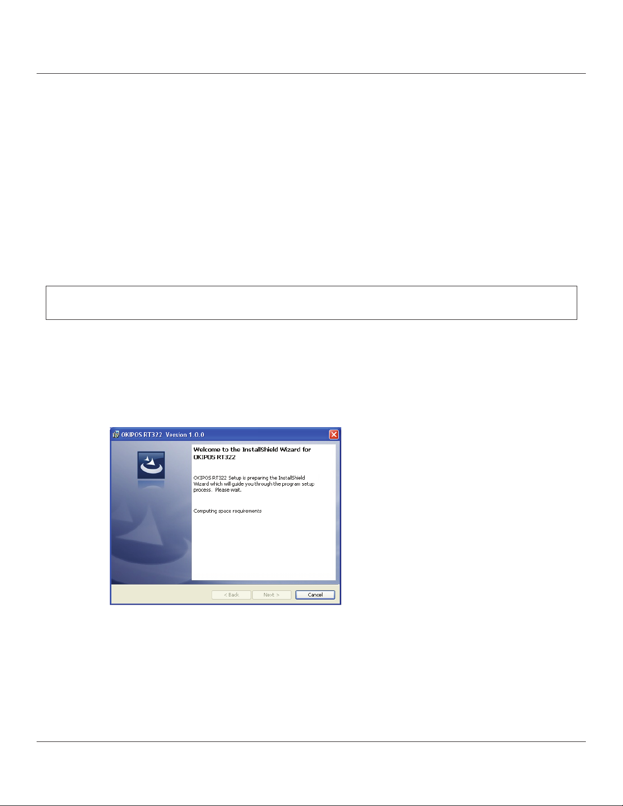
2. e following window appears, and the wizard prepares to start the installation.
e time required for installation may be longer than usual depending on the environment used.
4
Page 5
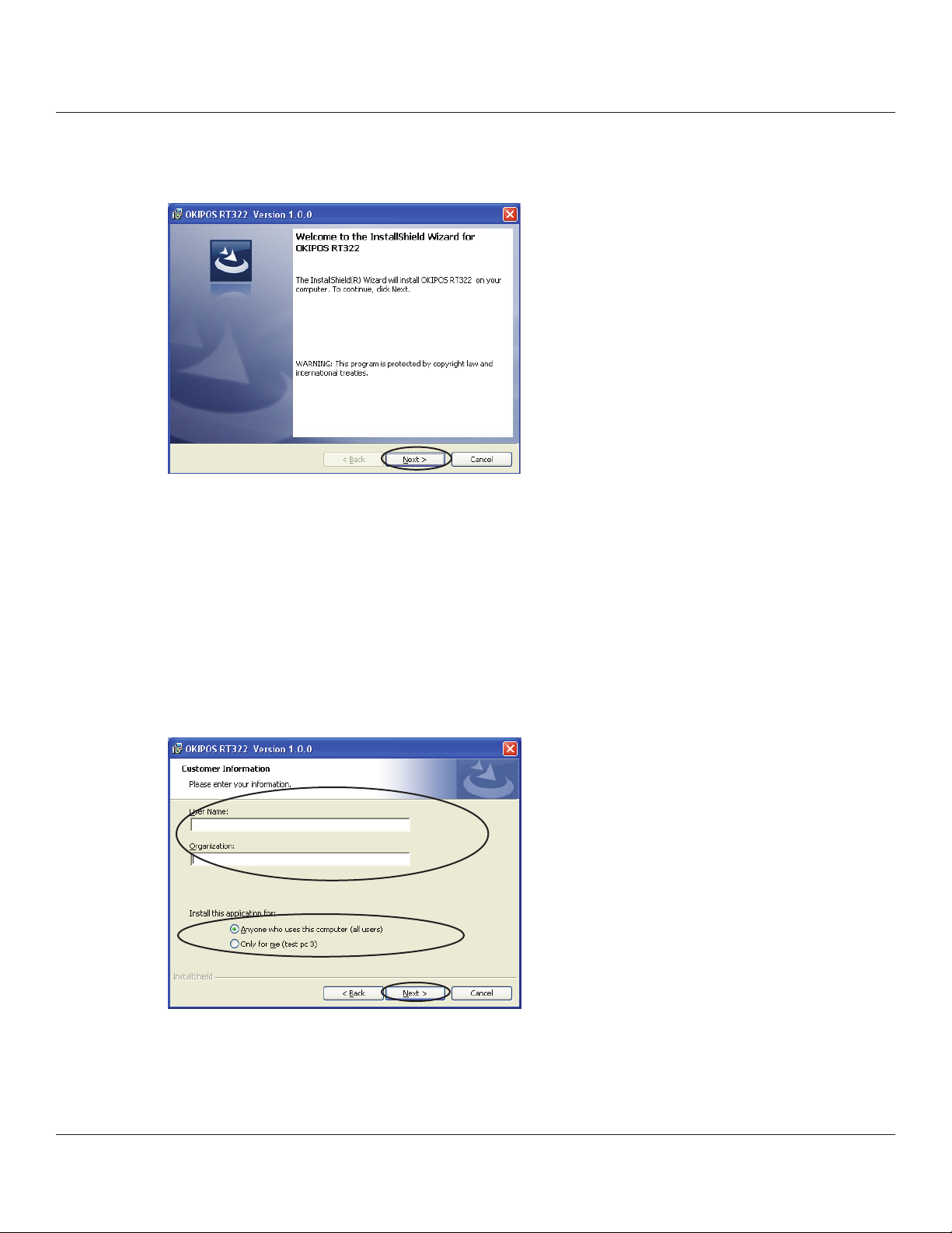
3. Click the [Next>] button to proceed.
4. Type your user information.
Aer typing your user name and the name of your organization and selecting whether the installed program is to
be available to all users of this computer or only to you, click the [Next>] button.
5
Page 6
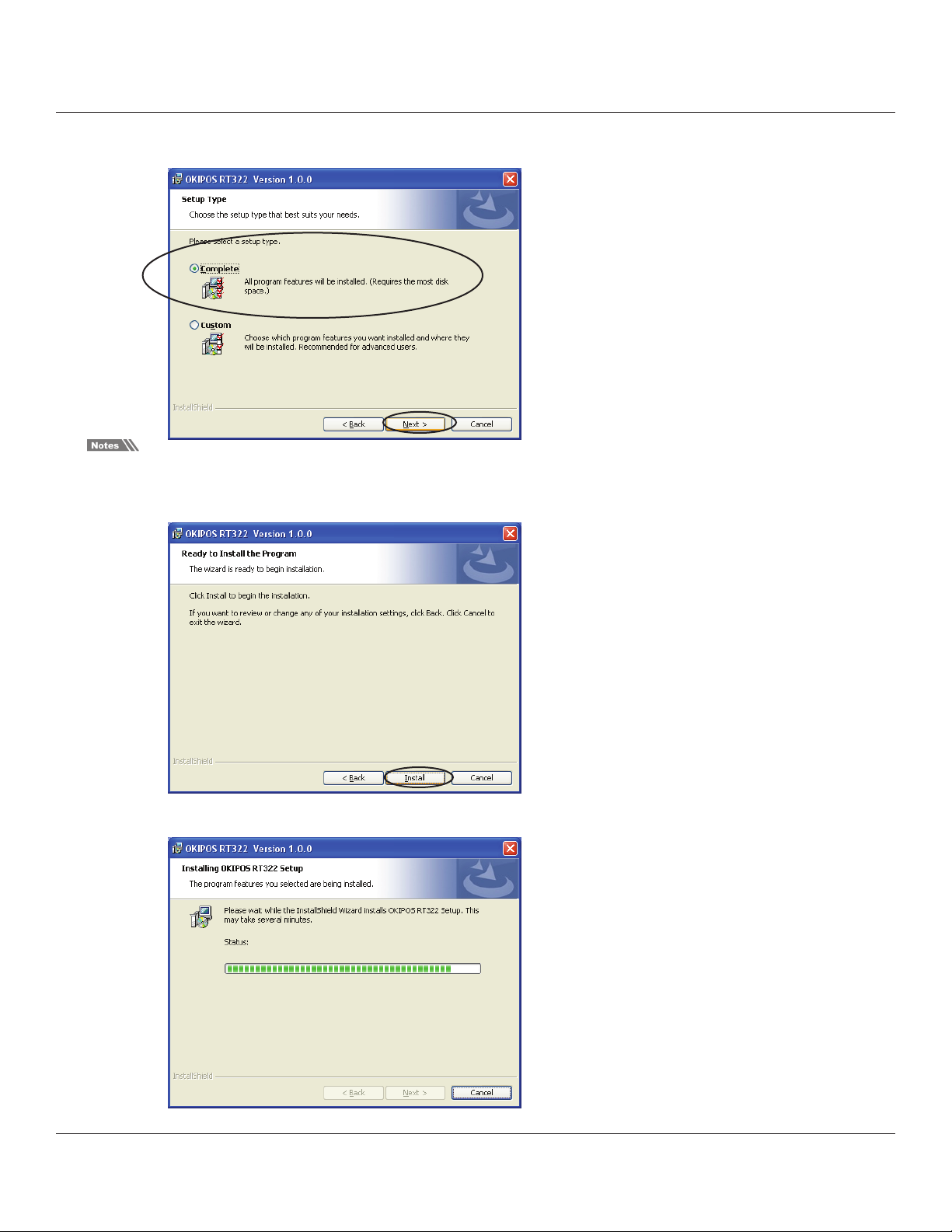
5. Select the type of setup.
Select Complete to install all of the program’s features, and then click the [Next>] button.
For Windows versions prior to Windows 2000 SP3, only the driver functions will be installed.
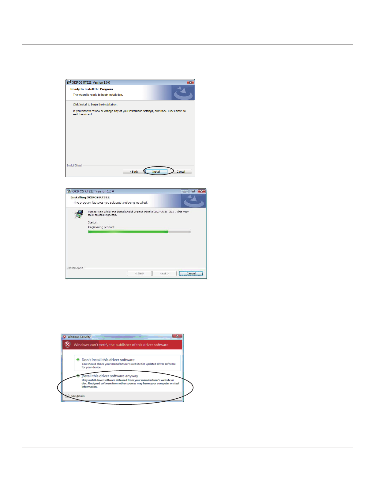
6. Click the [Install] button to begin the installation.
e program’s features are installed.
6
Page 7
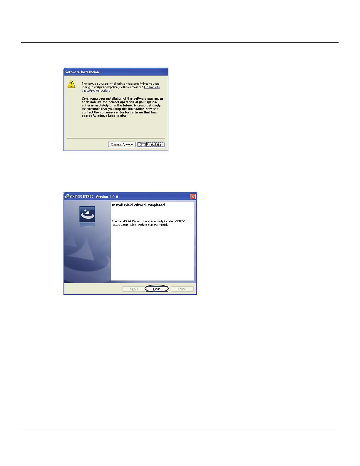
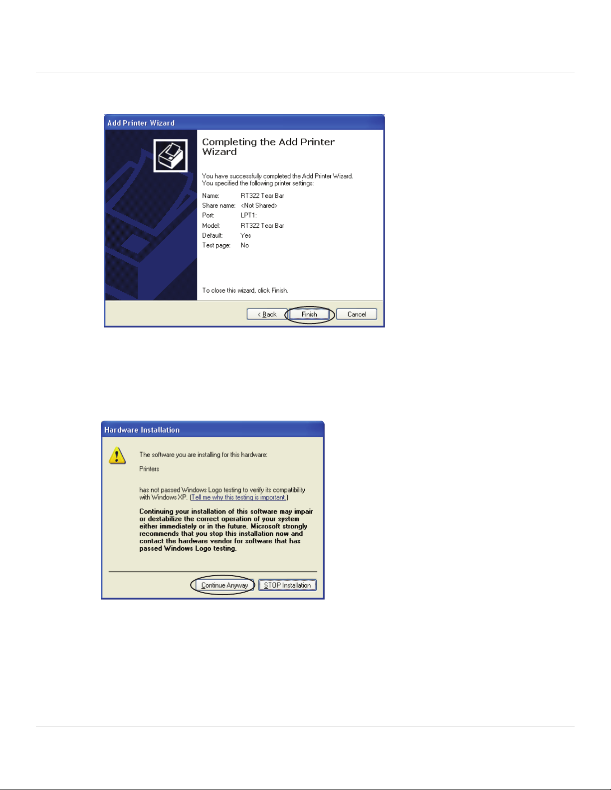
7. When the installation is complete, the Soware Installation conrmation dialog box will appear.
Click the [ Continue Anyway ] button.
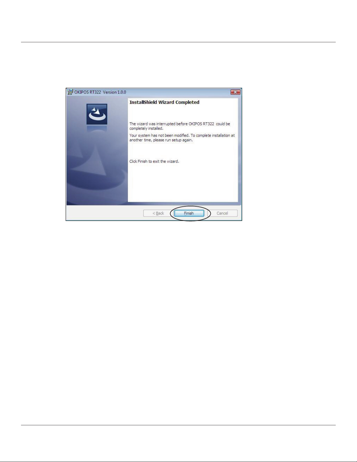
8. e wizard has completed installation of the program.
Click the [Finish] button to close the wizard.
9. e remaining installation steps vary according to the type of interface.
Continue to add the printer according to the steps for the interface that you are using.
1.1.1 USB Interface
1.1.2 Non-USB Interface
7
Page 8
1.1.1 USB Interface
To add a printer, proceed as follows.
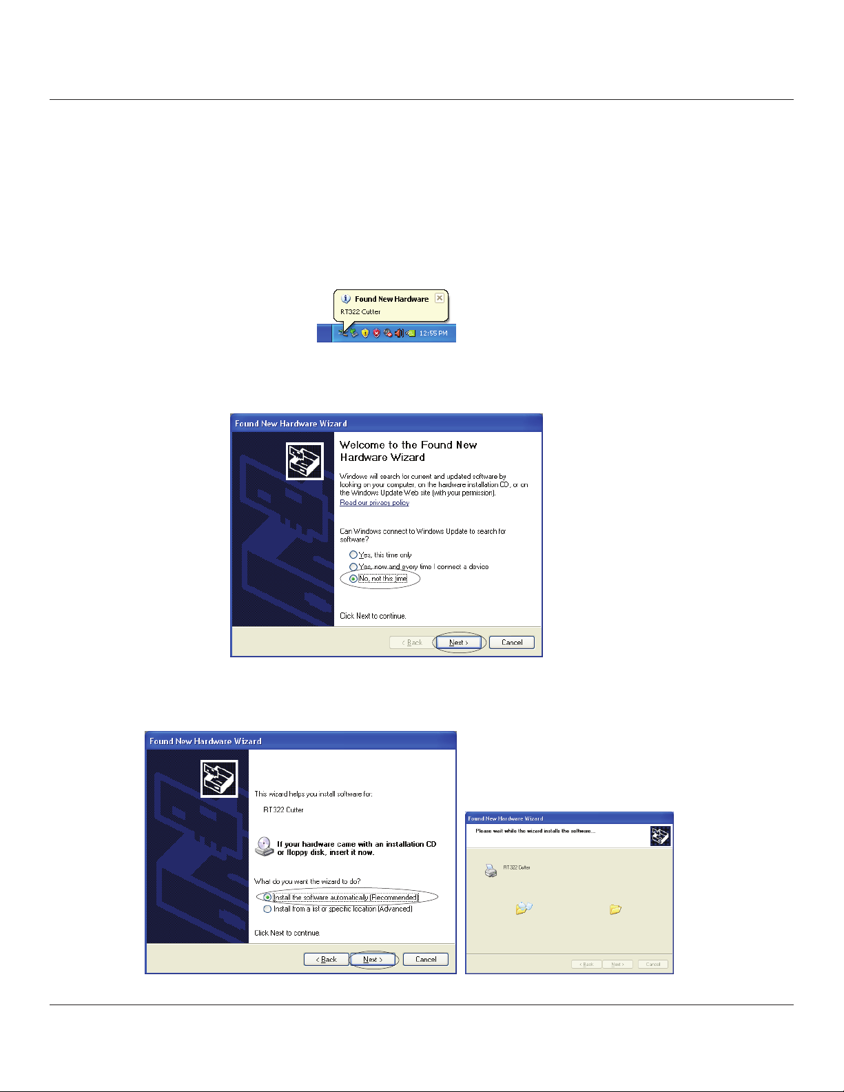
1. Connect the printer, and then turn on the printer’s power switch.
e Plug and Play feature detects the connection of the printer hardware and automatically starts installing the driver
soware.
At this time, the following message will appear on the lower right of the Windows desktop.
2. In the following dialog box, select No, not this time, and then click the [Next>] button.
3. In the following dialog box, select Install the soware automatically (Recommended), and then click the [Next>]
button.
8
Page 9
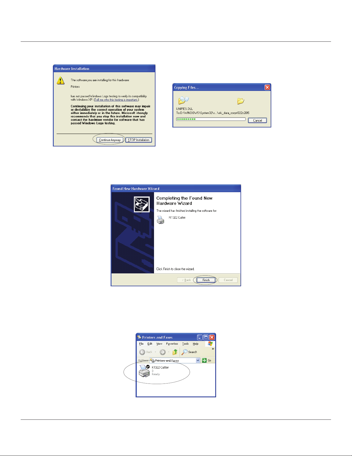
4. In the Hardware Installation dialog box, click the [Continue Anyway] button.
5. If installation was completed successfully, the following dialog box will appear.
Click the [Finish] button to complete the installation.
6. From the Windows Start menu, select Printers and Faxes and conrm that RT322 Cutter or RT322 Tear Bar appears
in the folder. If the appropriate printer appears there, installation was completed successfully.
9
Page 10
1.1.2 Non-USB Interface
To add a printer, proceed as follows.
When using a TCP/IP interface, the port must be congured beforehand.
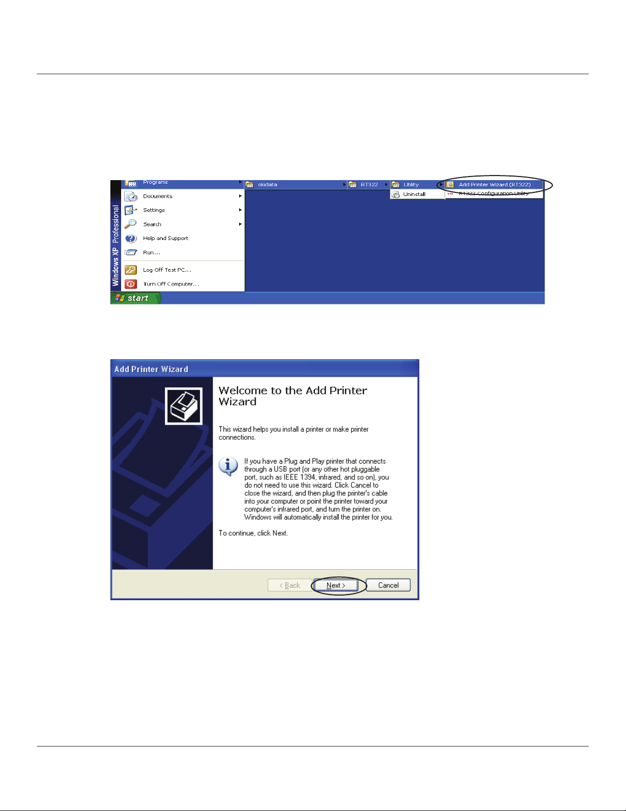
1. From the Windows Start menu, select Programs – Okidata – RT322 – Utility – Add Printer Wizard (RT322).
2. In the Add Printer Wizard dialog box, click the [Next>] button.
10
Page 11
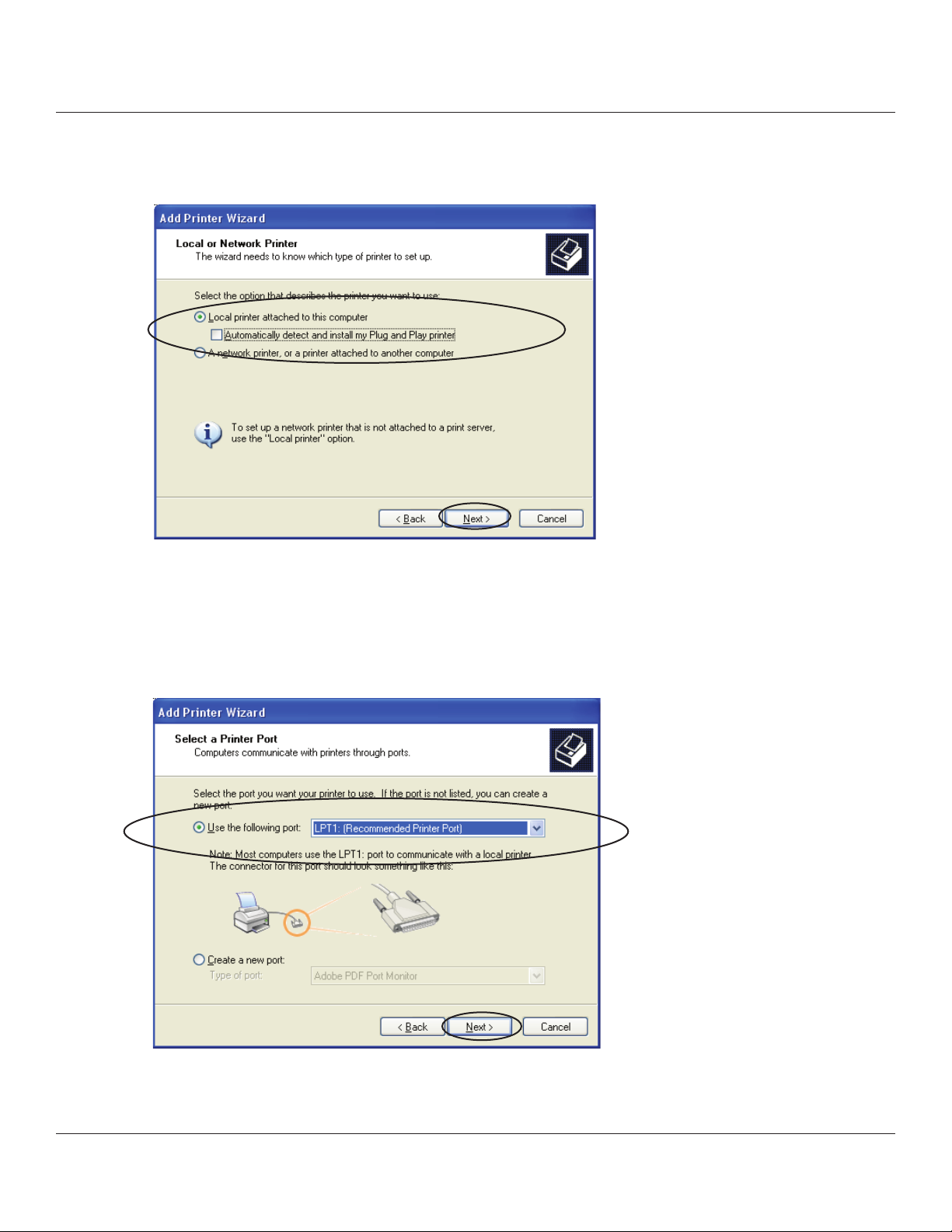
3. In the Local or Network Printer dialog box, select Local printer attached to this computer and uncheck Automatically
detect and install my Plug and Play printer. Click the [Next>] button to proceed.
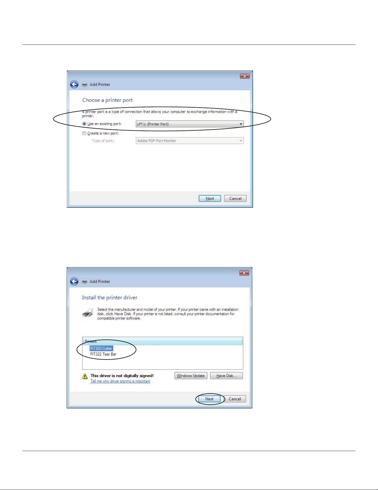
4. In the Select a Printer Port dialog box, select the port to use, and then click the [Next>] button.
11
Page 12
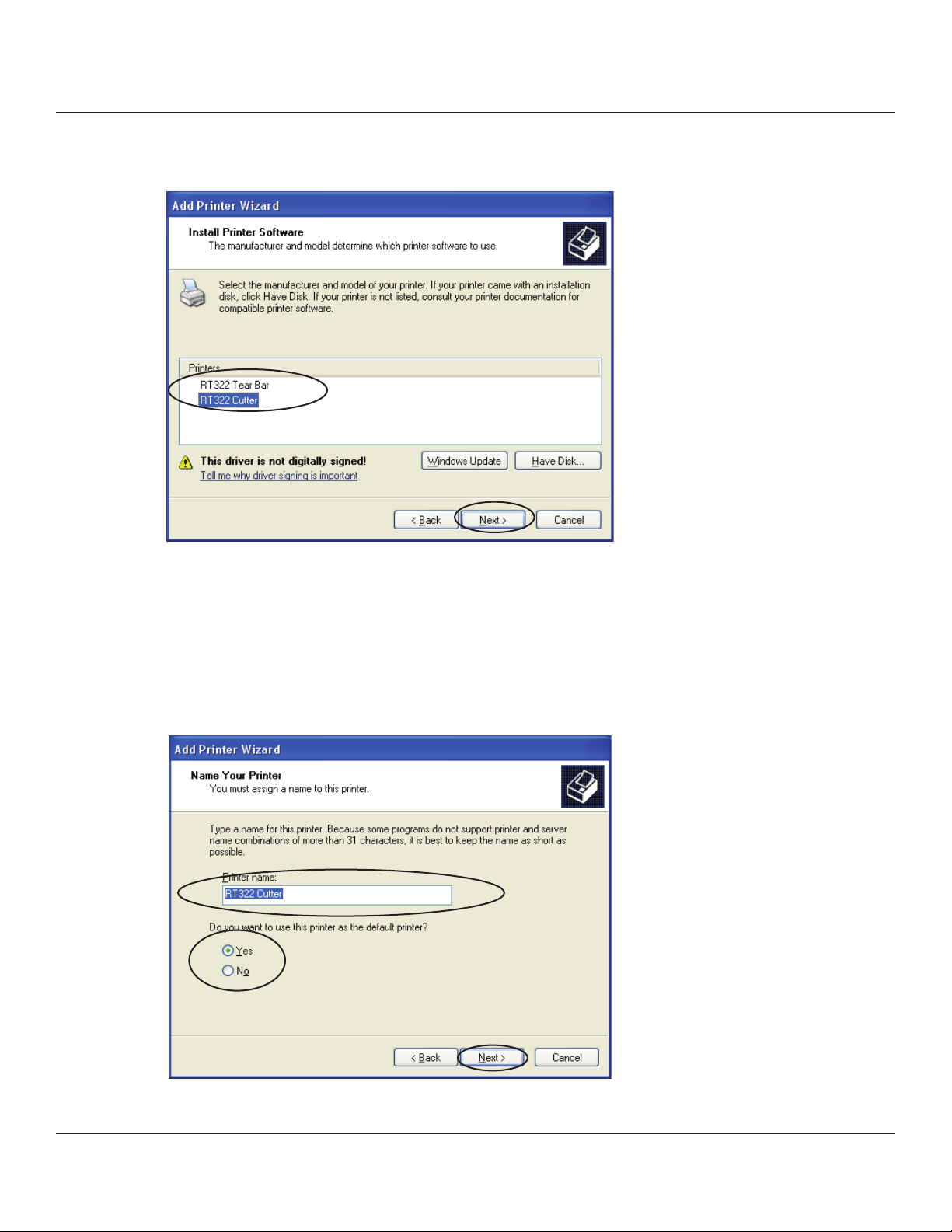
5. Select the printer to install, and then click the [Next>] button.
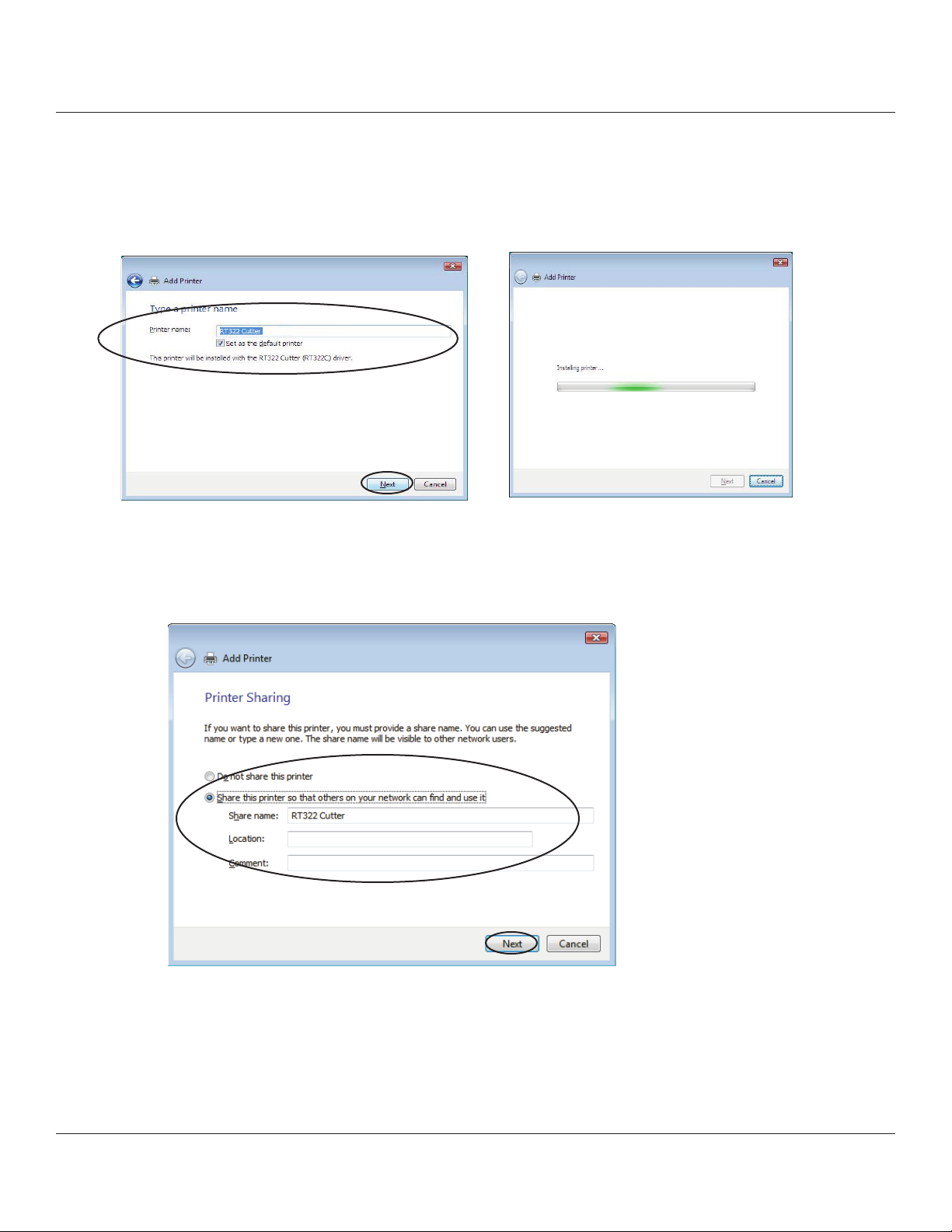
6. Specify the printer name that will be used aer installation in Windows-based programs. Type the printer name if you
wish to change it. Additionally, you may set the printer currently being installed as the default printer. Conrm the
settings, and then click the [Next>] button.
12
Page 13
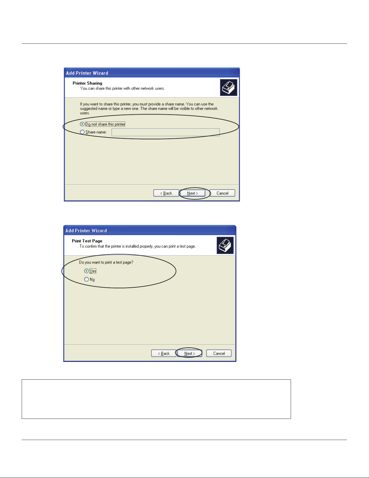
7. Make the appropriate printer-sharing settings, and then click the [Next>] button.
8. Select Yes to print a test page or No to not print one, and then click the [Next>] button.
Important: When using a serial interface, do not print the test page.
Conrm the printer and printer port settings when printing via a serial
interface. For details, refer to “5.1 Notes for printing via a Serial Interface” at
the end of the manual.
13
Page 14
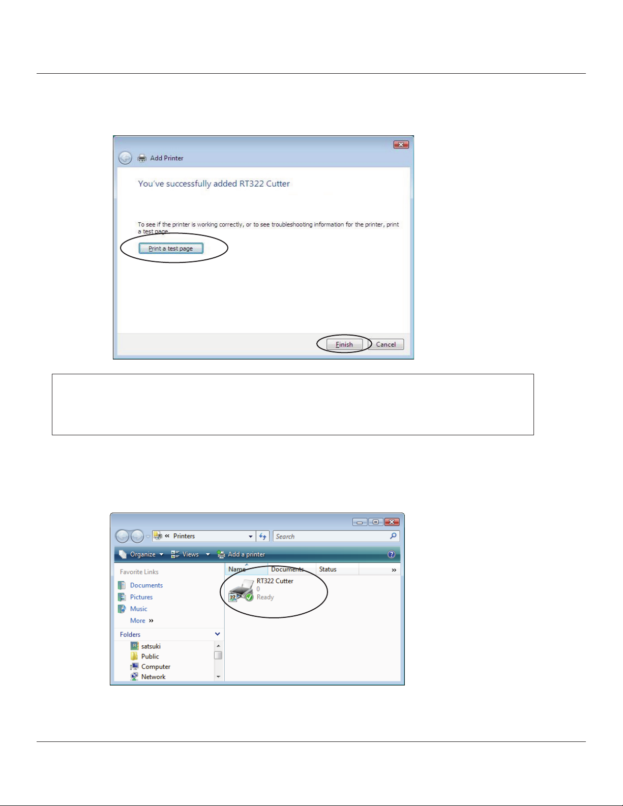
9. e settings are displayed. If the settings are correct, click the [Finish] button to add the printer
10. In the Hardware Installation dialog box, click the [Continue Anyway] button.
14
Page 15
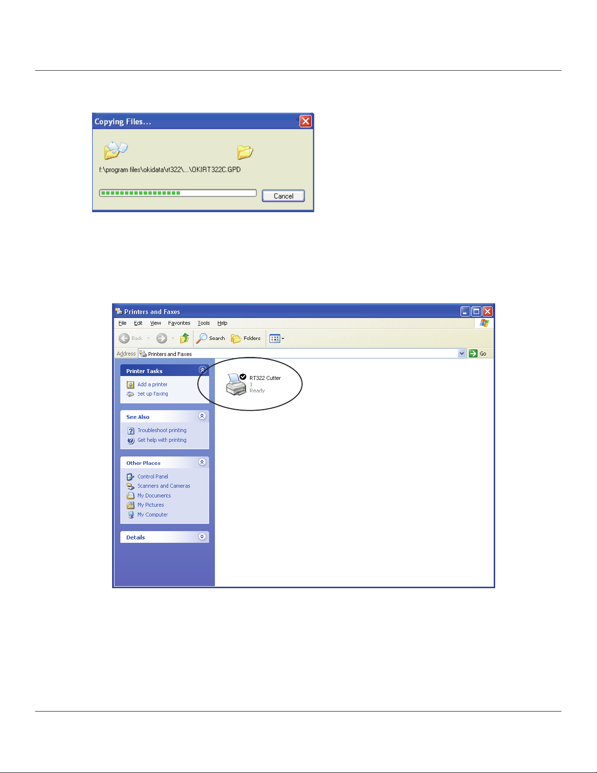
e les are copied.
11. From the Windows Start menu, select Printers and Faxes and conrm that RT322Cutter or RT322 Tear Bar appears in
the folder. If the appropriate printer appears there, installation was completed successfully.
15
Page 16
1.2 Installing (Windows Vista 32-Bit Edition)
To install the driver, proceed as follows.
Important : When using a USB interface, turn on the printer’s power aer performing steps 1 to 9 .
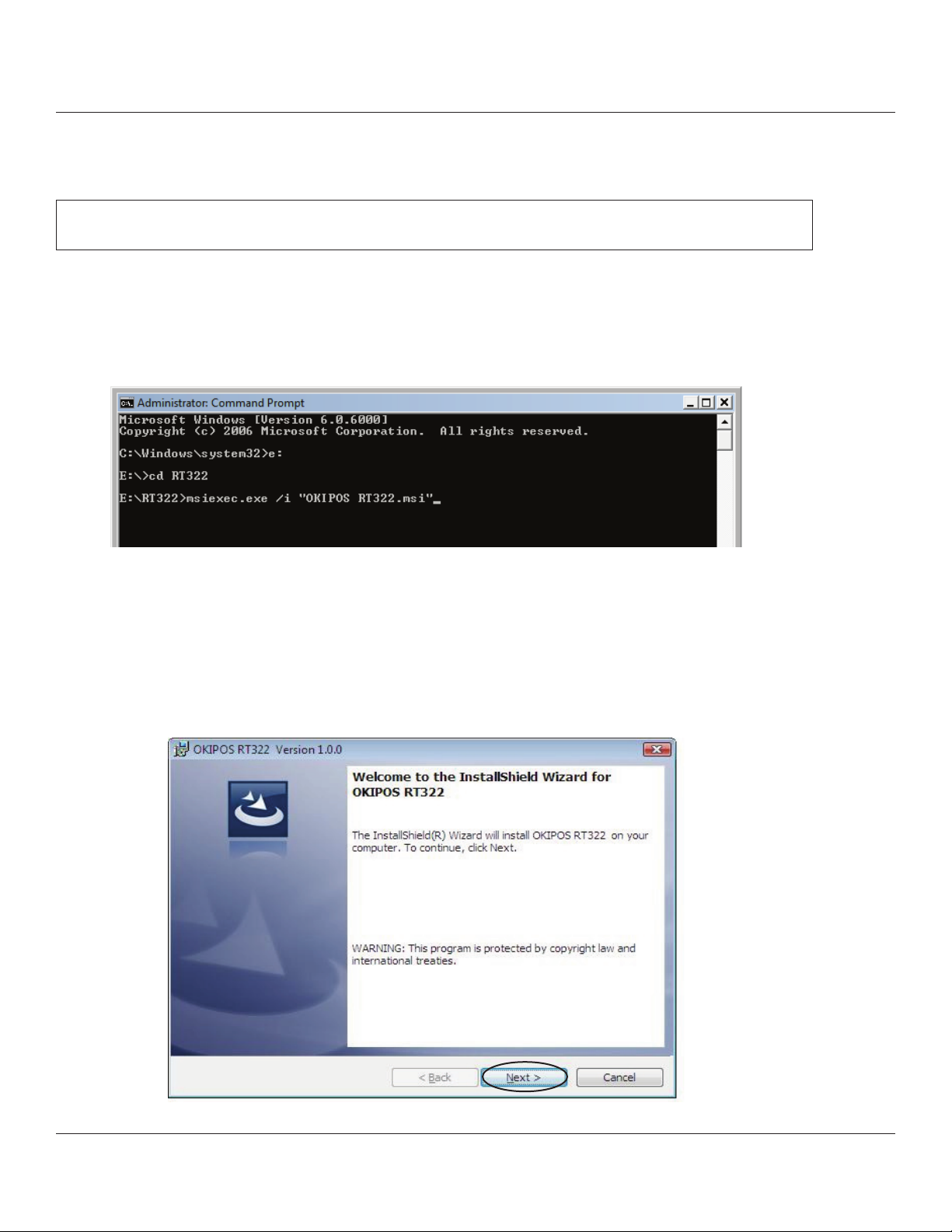
1. Fom the Windows Startmenu, select Programs - Accessories , right-click Command Prompt, and then Run as
administrator.
2. At the command prompt, perform the OKIPOS Driverset msi installer as follows.
3. In the User Account Control dialog box, click the [Continue] or [Allow] button.
e following window appears, and the wizard prepares to start the installation.
e time required for installation may be longer than usual depending on the environment used.
4. Click the [Next>] button to proceed.
16
Page 17
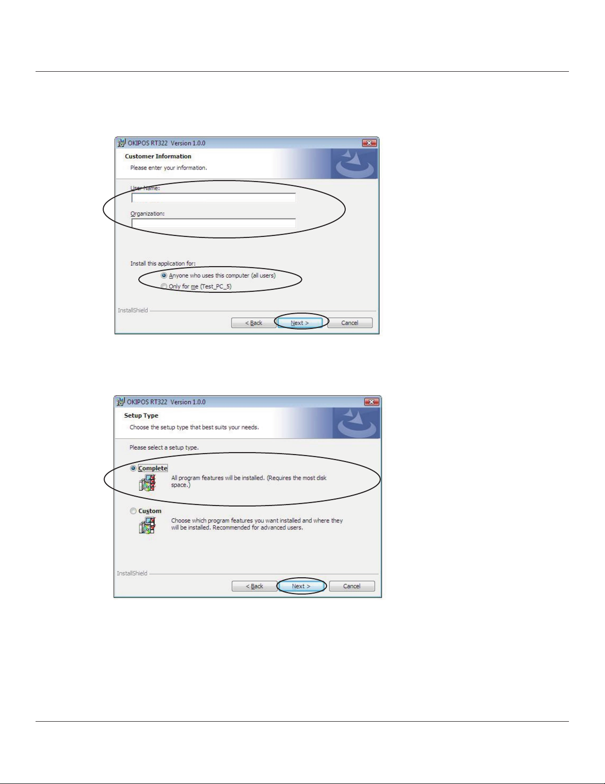
5. Type your user information.
Aer typing your user name and the name of your organization and selecting whether the installed program is to be
available to all users of this computer or only to you, click the [Next>] button.
6. Select the type of setup.
Select Complete to install all of the program’s features, and then click the [Next>] button.
17
Page 18
7. Click the [Install] button to begin the installation.
8. In the soware installation conrmation dialog box, click Install this driver soware anyway to continue
with installation. e conrmation dialog box will appear multiple times.
18
Page 19
9. e wizard has completed installation of the program.
Click the [Finish] button to close the wizard.
10. e remaining installation steps vary according to the type of interface.
Continue to add the printer according to the steps for the interface that you are using.
1.2.1 USB Interface
1.2.2 Non-USB Interface
19
Page 20
1.2.1 USB Interface
To add a printer, proceed as follows.
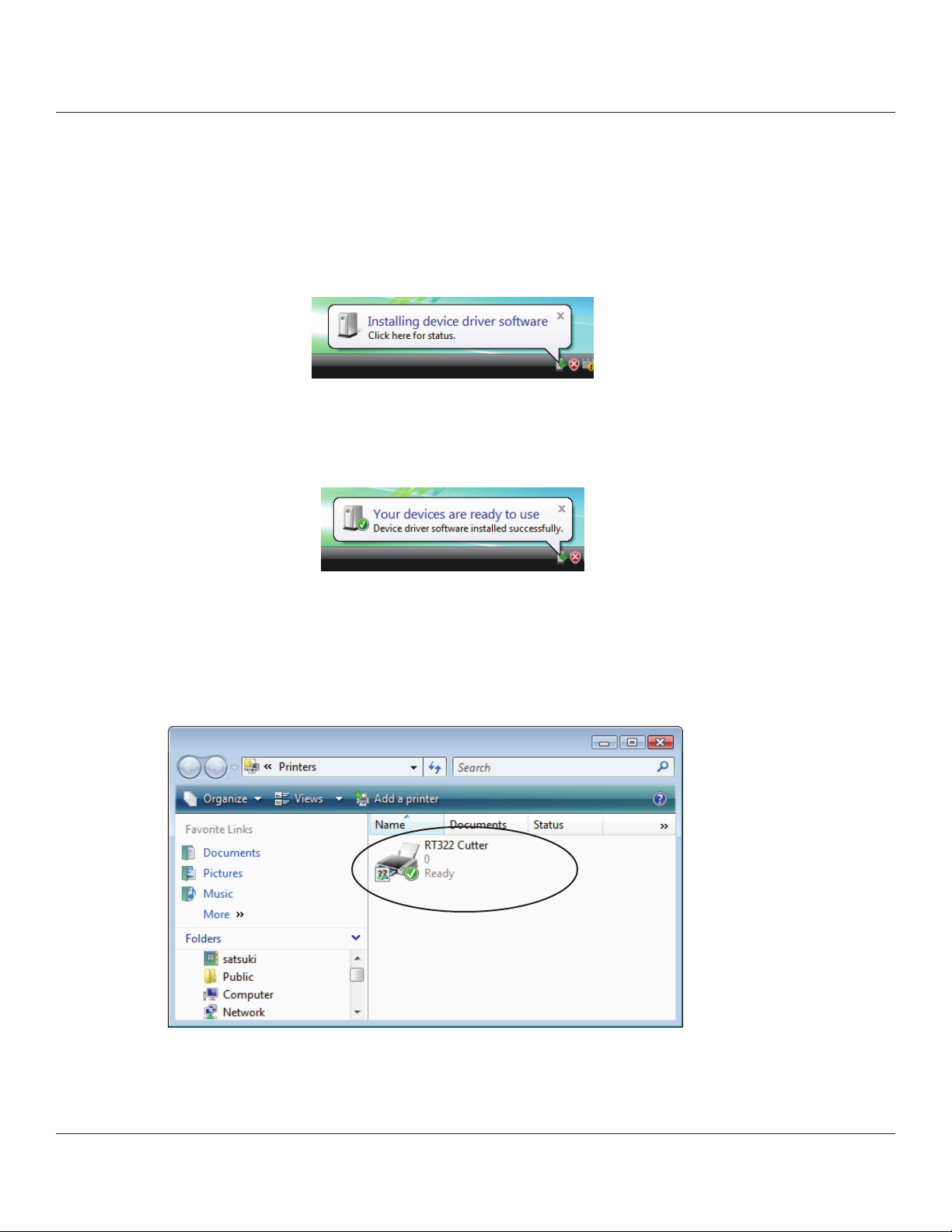
1. Connect the printer, and then turn on the printer’s power switch.
e Plug and Play feature detects the connection of the printer hardware and automatically installs the driver
soware.
If installation was completed successfully, the following message will appear on the lower right of the Windows
desktop.
2. From the Windows Start menu, select Settings – Printers to display the printer setting dialog box.
Conrm that RT322 Cutter or RT Tear Bar appears in the folder. If the appropriate printer appears there, installation
was completed successfully.
20
Page 21
1.2.2 Non-USB Interface
To add a printer, proceed as follows.
When using a TCP/IP interface, the port must be congured beforehand.
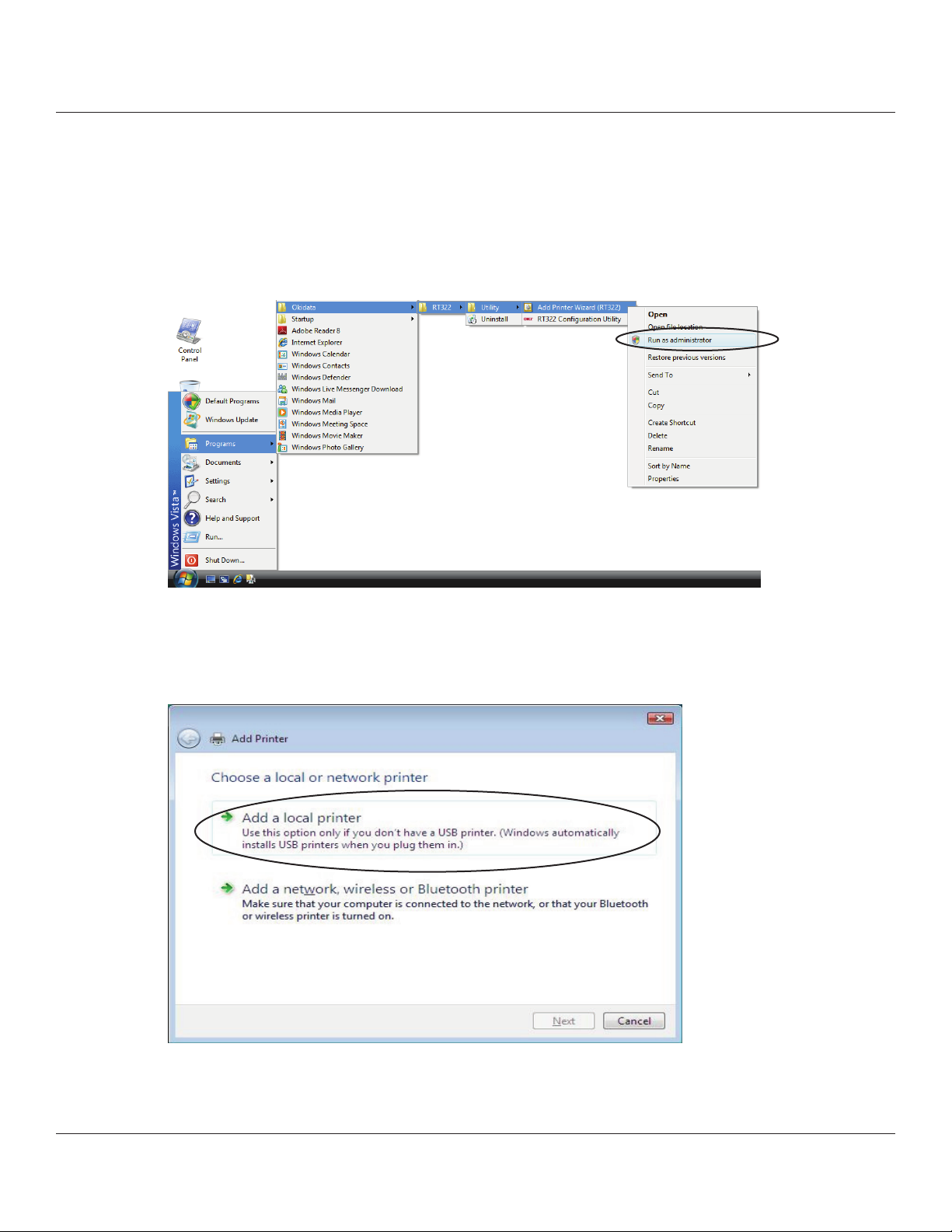
1. From the Windows Start menu, select Programs – Okidata – RT322 – Utility, right-click Add Printer Wizard (RT322),
and then select Run as administrator.
2. In the User Account Control dialog box, click the [ Continue ] or [ Allow ] button.
3. In the Choose a local or network printer dialog box, click Add a local printer.
21
Page 22
4. In the Choose a printer port dialog box, select the port to use, and then click the [Next] button.
5. Select the printer to install, and then click the [Next] button
22
Page 23
6. Specify the printer name that will be used aer installation in Windows-based programs. Type the printer
name if you wish to change it. Additionally, you may set the printer currently being installed as the default printer.
Click the [Next] button to begin the installation.
7. Make the appropriate printer-sharing settings, and then click the [Next] button.
23
Page 24
8. If installation was completed successfully, the following dialog box will appear. To print a test page, click the [Print a test
page] button. Click the [Finish] button to complete the installation.
Important: When using a serial port, do not print the test page.
Conrm the printer and printer port settings when printing via a serial port.
For details, refer to “5.1 Notes for Printing via a Serial Interface” at the end of
the manual.
9. From the Windows Start menu, select Settings – Printers to display the printer setting dialog box. Conrm that RT322
Cutter or RT322 Tear Bar appears in the folder. If the appropriate printer appears there, installation was completed
successfully.
24
Page 25
1.3 Installing ( Windows Vista 64-Bit Edition )
To install the driver, proceed as follows.
Important : When using a USB interface, turn on the printer’s power aer performing steps 1
1. Create a new folder in a location of your choosing on the computer (ex., “RT322” on the desktop), and
then copy the les of Printer Driver Set. (e compressed data can be used aer copying it.)
2. e remaining installation steps vary according to the type of interface.
Continue to add the printer according to the steps for the interface that you are using.
1.3.1 USB Interface
1.3.2 Non-USB Interface
25
Page 26
1.3.1 USB Interface
To add a printer, proceed as follows.
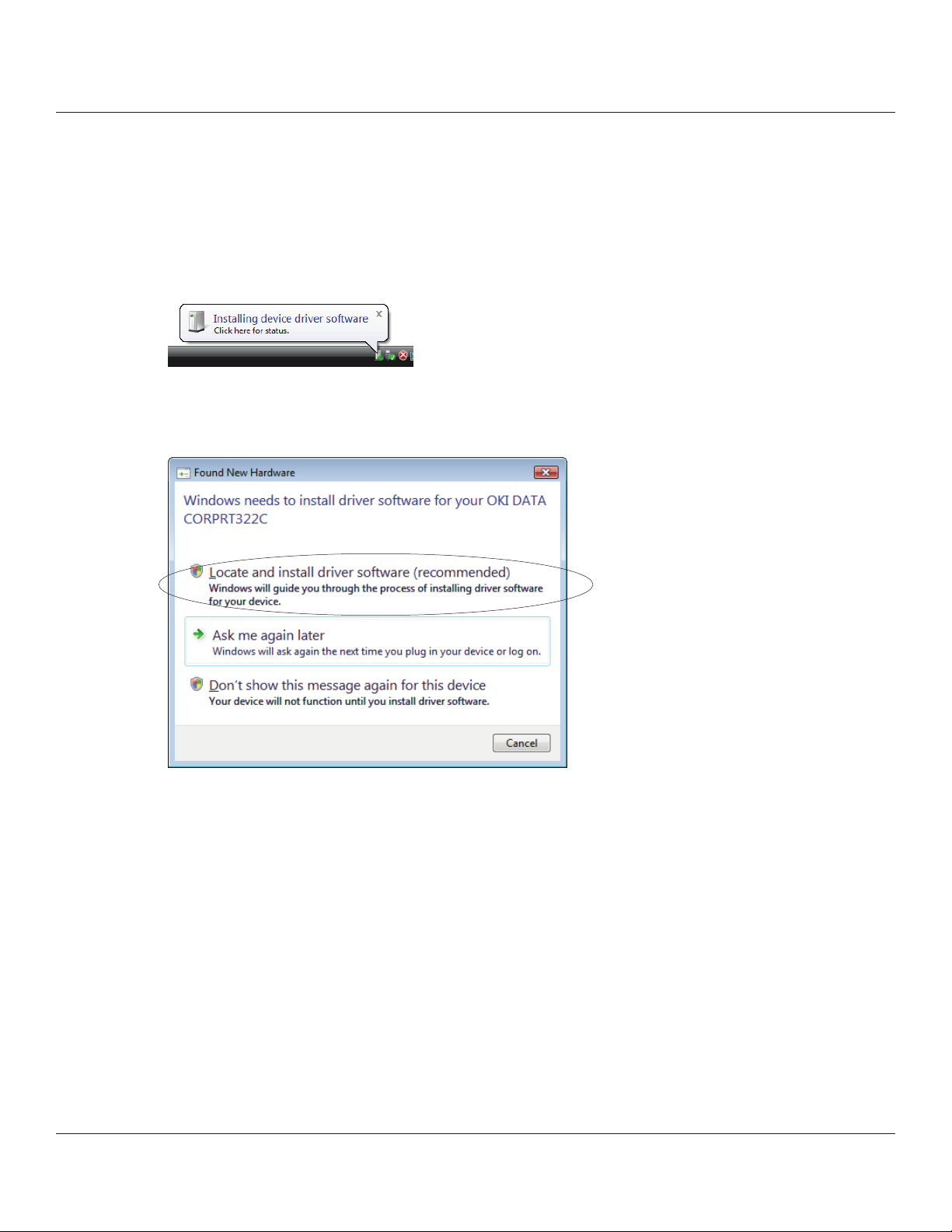
1. Connect the printer, and then turn on the printer’s power switch.
e Plug and Play feature detects the connection of the printer hardware and automatically starts installing the driver
soware.
2. In the following dialog box, click Locate and install driver soware (recommended).
3. In the User Account Control dialog box, click the [Continue] or [Allow] button.
Installation begins.
e time required for installation may be longer than usual depending on the environment used.
26
Page 27
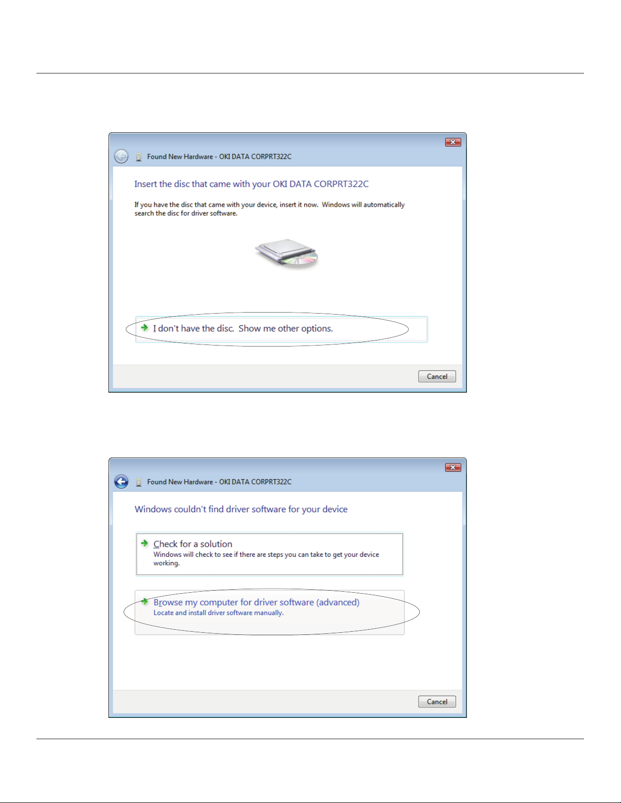
4. e following dialog box will appear.
e previously copied driver will be used; therefore, click I don’t have the disc. Show me other options.
5. Click Browse my computer for driver soware (advanced).
27
Page 28
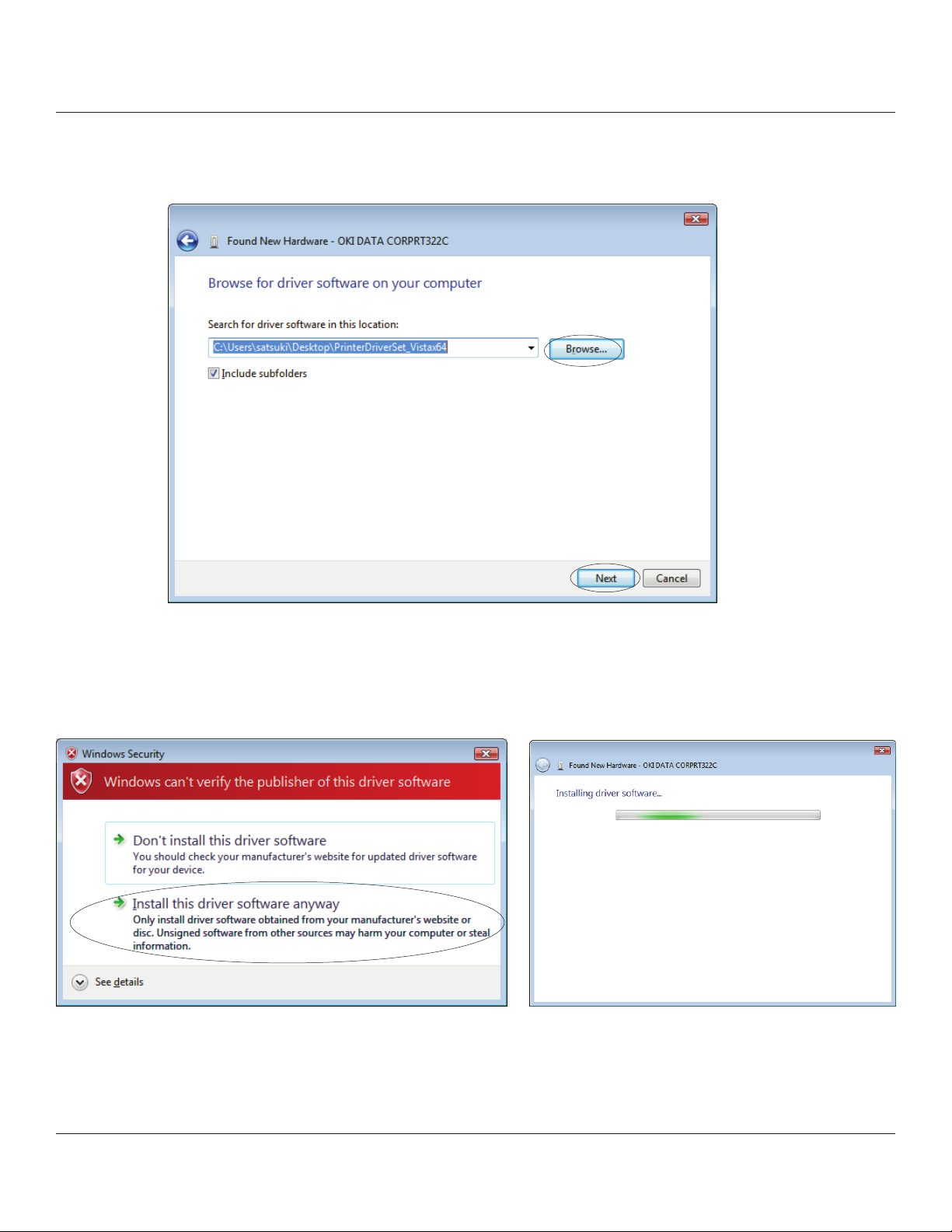
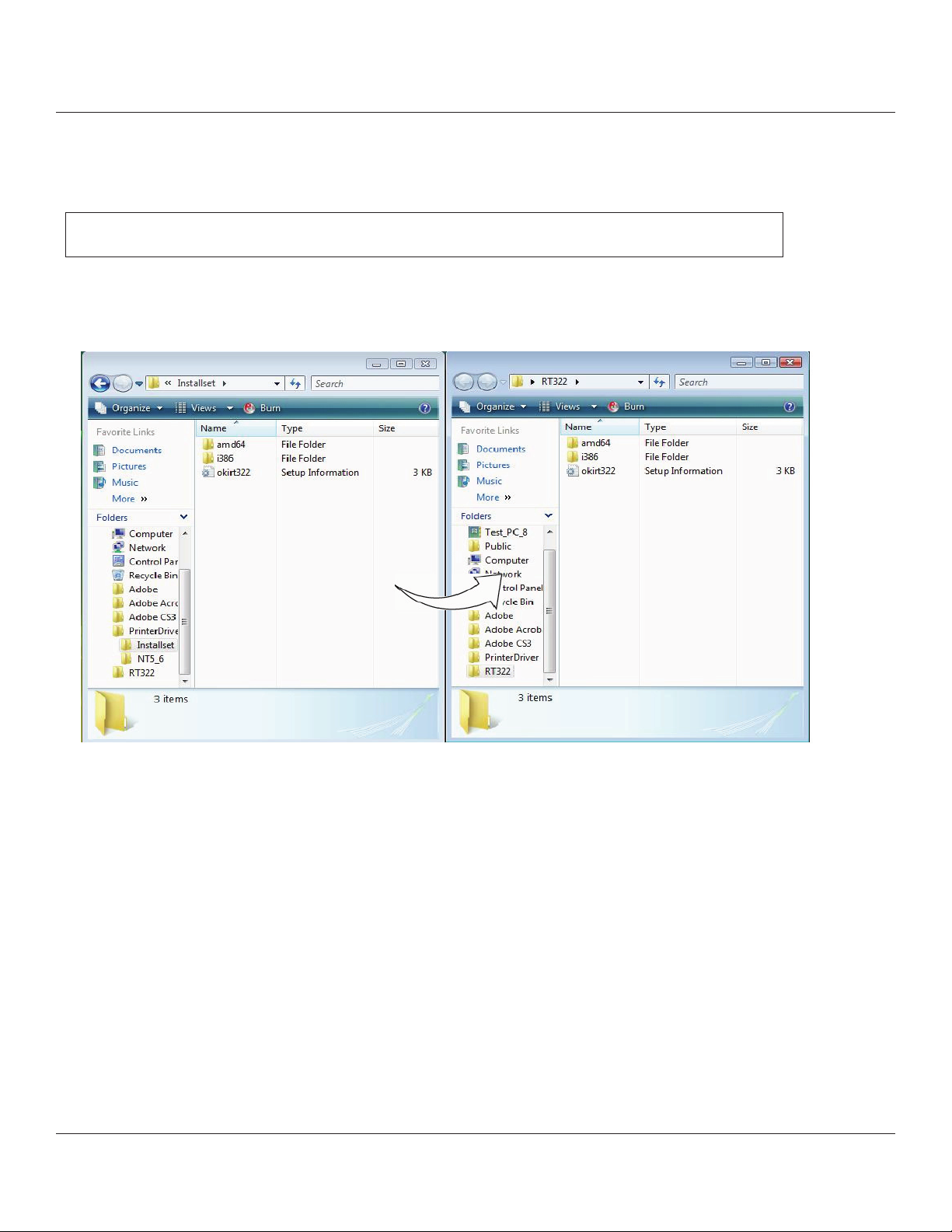
6. Click the [Browse…] button, select the Installset folder (ex., RT322\Installset on the desktop) in the previously
created folder, and then click the [Next] button.
7. In the soware installation conrmation dialog box, click Install this driver soware anyway to continue with
installation.
28
Page 29
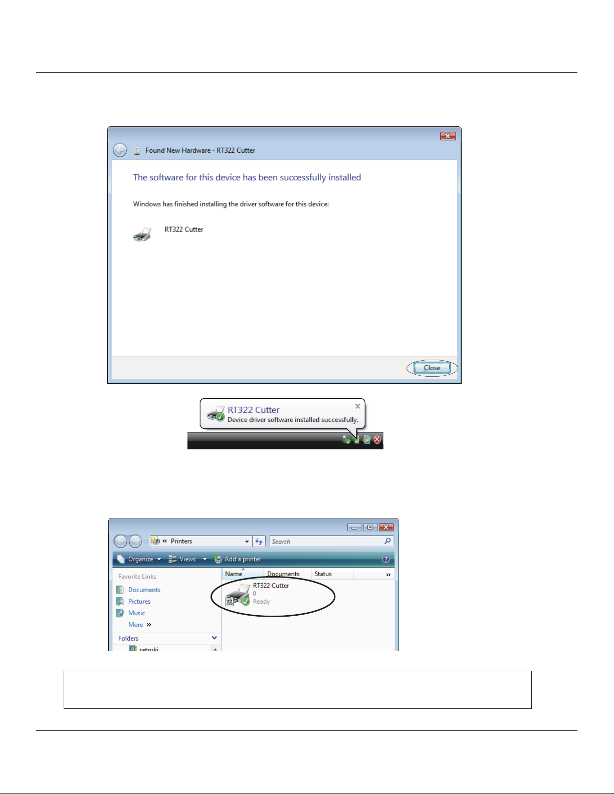
8. If installation was completed successfully, the following dialog box will appear.
Click the [Close] button to complete the installation.
9. From the Windows Start menu, select Settings – Printers to display the printer setting dialog box.
Conrm that RT322 Cutter or RT322 Tear Bar appears in the folder. If the appropriate printer appears there,
installation was completed successfully.
Important: e folder created in a location of your choosing during installation and
the les it contains are no longer necessary; therefore, delete them.
29
Page 30
1.3.2 Non-USB Interface
To add a printer, proceed as follows.
When using a TCP/IP interface, the port must be congured beforehand.
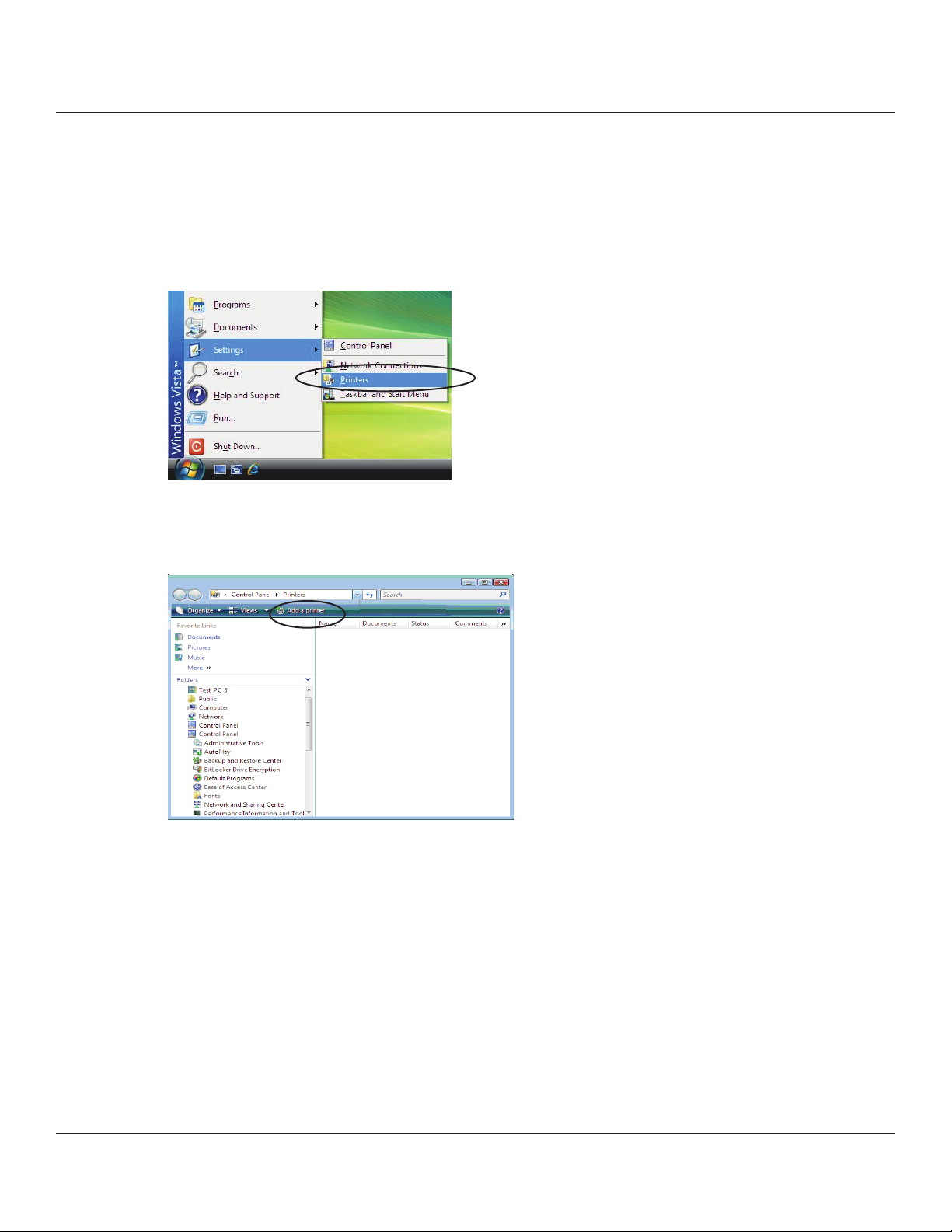
1. From the Windows Start menu, select Settings – Printers.
2. In the printer setting dialog box, click Add a printer.
30
Page 31

3. Click Add a local printer.
4. In the Choose a printer port dialog box, select the port to use, and then click the [Next] button.
5. In the Install the printer driver dialog box, click the [Have Disk...] button.
31
Page 32

6. In the Install from Disk dialog box, click the [Browse...] button to display the Locate File dialog box. In the previously
created folder, open the Installset folder (ex., RT322\Installset on the desktop), select “okirt322.inf”, and then click the
[Open] button.
7. Click the [OK] button.
32
Page 33

8. In the Install the printer driver dialog box, select the printer to use, and then click the [Next] button.
9. Specify the printer name that will be used aer installation in Windows-based programs. Type the printer name if you
wish to change it. Additionally, you may set the printer currently being installed as the default printer.
Click the [Next] button to begin the installation.
10. In the User Account Control dialog box, click the [Continue] or [Allow] button.
e printer is installed.
33
Page 34

11. In the soware installation conrmation dialog box, click Install this driver soware anyway to continue with
installation. e conrmation dialog box will appear multiple times.
12. If installation was completed successfully, the following dialog box will appear. To print a test page, click
the [Print a test page] button. Click the [Finish] button to complete the installation.
Important: When using a serial port, do not print the test page.
Conrm the printer and computer printer port settings when printing via a serial port.
For details, refer to “5.1 Notes for Printing via a Serial Interface” at the end of the manual.
34
Page 35

13. From the Windows Start menu, select Settings – Printers to display the printer setting dialog box.
Conrm that RT322 Cutter or RT322 Tear Bar appears in the folder. If the appropriate printer appears there,
installation was completed successfully.
Important: e folder created in a location of your choosing during installation
and the les it contains are no longer necessary; therefore, delete them.
35
Page 36

1.4 Uninstalling
1.4.1 Windows 2000/XP
To uninstall the driver, proceed as follows.
1. Turn o the power switch of the RT322.
2. From the Windows Start menu, select Programs – Okidata – RT322 – Uninstall.
3. When the following conrmation dialog box appears, click the [Yes] button to continue.
4. e uninstaller launches to remove all of the RT322 soware from your computer.
36
Page 37

1.4.2 Windows Vista 32-Bit Edition
To uninstall the driver, proceed as follows.
1. Turn o the power switch of the RT322.
2. From the Windows Start menu, select Programs – Okidata – RT322, right-click Uninstall, and then Run as
administrator.
3. In the User Account Control dialog box, click the [Continue] or [Allow] button.
When the following conrmation dialog box appears, click the [Yes] button to continue.
37
Page 38

4. If the print spooler conrmation dialog box appears, select Do not close applications, and then click the [OK] button.
(Although “A reboot will be required” is indicated, the computer will not restart.)
5. e uninstaller launches to remove all of the RT322 soware from your computer.
38
Page 39

1.4.3 Windows Vista 64-Bit Edition
To uninstall the driver, proceed as follows.
1. Turn o the power switch of the RT322.
2. From the Windows Start menu, select Settings – Printers to open the printers folder.
Right-click the RT322 printer icon and then select Run as administrator – Delete.
3. In the User Account Control dialog box, click the [Continue] or [Allow] button.
4. When the following conrmation dialog box appears, click the [Yes] button to continue.
39
Page 40

5. Right-click a blank area in the printers folder, and then select Run as administrator – Server Properties.
6. In the User Account Control dialog box, click the [Continue] or [Allow] button.
7. In the Print Server Properties dialog box, click the Drivers tab.
Select the OKI RT322 printer, and then click the [Remove...] button.
40
Page 41

8. e dialog box to select the deletion method will appear.
Select Remove driver and driver package, and then click the [OK] button.
9. When the following conrmation dialog box appears, click the [Yes] button to continue.
10. e following dialog box will appear. Click the [Delete] button to continue.
41
Page 42

Important: If the dialog box shown in step 11 does not appear aer performing step 10, the
driver(s) and driver package(s) were not deleted successfully. Restart the
computer, and then perform the uninstalling procedure again from step 5.
11. If the driver(s) and driver package(s) were deleted, the following dialog box will appear. Click the [OK] button.
12. If the RT322 printer no longer appears in the following Print Server Properties dialog box, the uninstalling procedure
was completed successfully. Click the [Close] button to close the dialog box.
42
Page 43

2. Features
2.1 RT322 Driver
is driver can be used to set basic printing functions, such as the print mode and paper types, and it can also be used to
make graphic logo settings and advanced settings for peripheral units (buzzer and cash drawer).
e following is an example of driver settings when using the buzzer (optional).
Example of driver settings:
Peripheral Unit Type Buzzer
Peripheral Unit 1 Document Bottom
Peripheral Unit 2 No Use
Buzzer 1: On Time 500 milliseconds
Buzzer 1: O Time 2000 milliseconds
Buzzer 1: Cycles 5
The total buzzer time, including on time and o time for the total number of cycles, should not exceed 30 seconds.
Click here to go to the description page regarding RT322 driver.
43
Page 44

2.2 OKI RT322 Conguration Utility
e OKI RT322 Conguration Utility provides an easy way to set the printer’s memory switches, to register graphic logos,
and to make other such hard print settings.
It also oers an easy way to set up an Ethernet interface cord.
Also, note that you may choose to install the utility only, without also installing the driver soware.
Important: is function is supported by Windows 2000 ( SP3 or later )/XP/Vista 32-bit edition.
Click here to go to the advanced okidata Conguration Utility page.
2.3 Virtual Port Emulator
By using this soware, printers equipped with a USB interface card or Ethernet interface card can be used with applications
that support only serial printers
Important: Some applications do not support this feature.
is function is supported by Windows 2000 (SP3 or later)/XP/Vista 32-bit edition.
Click here to go to the description page regarding Virtual Port Emulator setup.
44
Page 45

3. Windows 2000/XP/Vista Printer Driver Settings
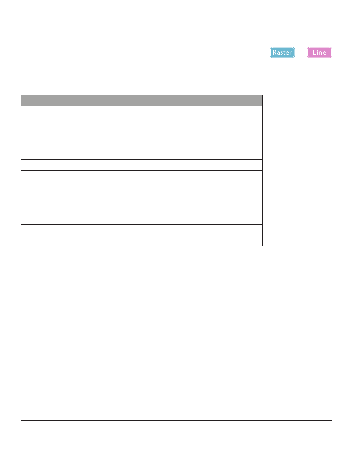
e driver supports two print modes: Raster mode and Line mode.
e default mode for this driver is Raster mode.
When printing via a USB interface, it is recommended to select Raster mode, and when printing via a serial interface,
it is recommended to select Line mode.
e features for each print mode are as follows.
Prints graphics at high speed.•
Suitable for reverse printing (wall mount mode).•
Supports device fonts.•
Suitable for printing barcode device fonts.•
In addition, this driver is able to set various functions for the RT322.
Paper Type
Page Cut Type
Document Cut Type
Document Feed Type
Print Speed
Print Density
Vertical Mount (reverse printing)
Document Top/Bottom Logo
Page Top/Bottom Logo
Peripheral Unit Type
Buzzer or Cash Drawer Interlocking Operation
Device Fonts
Barcode Fonts
Some functions cannot be set at the same time. If the mark is displayed in the Device Settings tab, refer to
Section 3.1 and after to conrm the settings.
○ ○
○ ○
○ ○
○ ○
○ ○
○ ○
○ ×
○ ○
× ○
○ ○
○ ○
× ○
× ○
45
Page 46

3.1 Setting the Printer
Using the printer’s Properties dialog box, you can set various functions of this driver.
Begin by opening the Properties dialog box, as follows.
1. From the Windows Start menu, select Printers and Faxes to open the folder.
2. In the folder, right-click the RT322 printer icon, and then select Properties to open the printer’s Properties dialog box.
3. Click the Device Settings tab.
46
Page 47

3.1.1 Print Mode
Sets the print mode. For details of each mode, refer to page 42.
Available settings are as follows.
Setting Default Meaning
Raster
Line Sets Line Mode
Setting the print mode:
○
Sets Raster Mode
In the explanations that follow for the various functions, the settings that can be made for Raster mode
and Line mode are dierent.
and line shown at the upper right of the pages in this manual to indicate that the
setting can be made for one or both of the print modes.
47
Page 48

3.1.2 Paper Type
Set this to the appropriate paper type.
Available settings are as follows.
Setting Default Meaning
Receipt
Ticket Fixed length: the printer outputs white-space padding up to the end
Setting the paper type:
○
Variable length: the printer does not output white-space padding at
the end of the page data.
of the xed-length page.
If you wish to carry out journal printing (without page breaks), set the paper type to Receipt (variable length)
and select a receipt-length paper size, such as 72 mm × Receipt, for the feed method and paper. (Refer to
Section 3.2.1.)
48
Page 49

3.1.3 Page Cut Type (RT322 Cutter Model Only)
Sets the cutting method for the end of each non-nal page of a document.
Available settings are as follows.
Setting Default Meaning
No Cut
Partial Cut Printer feeds paper to cut position, and then cuts it leaving one point at
Setting the page cutting:
○
Printer does not feed or cut paper.
the center.
49
Page 50

3.1.4 Document Cut Type (RT322 Cutter Model Only)
Sets the cutting method for the nal page of the document.
Available settings are as follows.
Setting Default Meaning
No Cut Printer does not feed or cut paper.
Partial Cut
Setting the document cutting:
○
Printer feeds paper to cut position, and then cuts it leaving one
point at the center.
50
Page 51

3.1.5 Document Feed Type (RT 322 Tear Bar Model Only)
Sets the document feed operation aer printing.
Available settings are as follows.
Setting Default Meaning
No Feed Printer does not feed paper aer printing document.
Tear Bar
Setting the document feeding:
○
Printer feeds paper to tear bar (cut position) aer printing the document.
51
Page 52

3.1.6 Print Speed
Set the print speed. Note that the setting also aects the print quality.
Available settings are as follows.
Setting Default Meaning
High
Middle Sets print quality and print speed to intermediate level.
Low Provides the highest print quality but lowers print speed.
Setting the print speed:
○
Priority is given to print speed over print quality.
52
Page 53

3.1.7 Print Density
Sets the print density.
Available settings are as follows.
Setting Default Meaning
-3 to -1 Larger value with – (minus) makes print density lighter.
Standard
+1 to +3 Larger value with + (plus) makes print density darker.
Setting the print density:
○
Prints with normal density.
53
Page 54

3.1.8 Vertical Mount (reverse printing)
Set this to Enable if the printer is mounted on the wall or is stood up vertically.
is setting makes it possible for the customer to view the printout in the correct orientation when the
printer is installed vertically.
Available settings are as follows.
Setting Default Meaning
Disable
Enable Printing is inverted, top to bottom. (Use when printer is
Selecting normal or reverse printing:
○
Prints normally.
mounted on wall or standing vertically.)
Important: e vertical mount (reverse printing) setting is enabled only when “Raster mode” is
selected for the print mode. Note that it is not possible to use the logo printing settings
and reverse printing at the same time.
54
Page 55

3.1.9 Document Top Logo
e NV logos are identied by their NV logo (image list) numbers.
To select a top-of-document logo, choose the appropriate logo number. Before making this setting, you must load NV logos
into the printer’s nonvolatile memory. For details about loading NV logos, refer to “4.1.2 NVLogo”.
Available settings are as follows.
Setting Default Meaning
No Logo Printed
Print Logo 1, …, 10 Prints the selected logo at the document top.
Selecting the top-of-document logo:
○
No logo printed at the document top.
Important: Note that it is not possible to use the logo printing settings and reverse printing at the
same time.
55
Page 56

3.1.10 Page Top Logo
To select a top-of-page logo, choose the appropriate NV logo (image list) number. Before making this
setting, you must load NV logos into the printer’s nonvolatile memory. For details about loading NV logos,
refer to “4.1.2 NVLogo”.
Available settings are as follows.
Setting Default Meaning
No Logo Printed
Print Logo 1, …, 10 Prints the selected logo at the Page top.
Selecting the top-of-page logo:
○
No logo printed at the Page top.
Important: e page top logo setting is enabled only when “Line mode”
Is selected for the print mode. Note that it is not possible to use the logo
printing settings and reverse printing at the same time.
56
Page 57

3.1.11 Page Bottom Logo
To select the bottom-of-page logo, choose the appropriate NV logo (image list) number. Before making this
setting, you must load NV logos into the printer’s nonvolatile memory. For details about loading NV logos,
refer to “4.1.2 NVLogo”
Available settings are as follows.
Setting Default Meaning
No Logo Printed
Print Logo 1, …, 10 Prints the selected logo at the page bottom.
Selecting the bottom-of-page logo:
○
No logo printed at the page bottom.
Important: Page bottom logo setting is enabled only when “Line mode” is selected for the
print mode. Note that it is not possible to use the logo printing settings and
reverse printing at the same time.
57
Page 58

3.1.12 Document Bottom Logo
To select the bottom-of-document logo, choose the appropriate NV logo (image list) number. Before making this setting,
you must load NV logos into the printer’s nonvolatile memory. For details about loading NV logos, refer to “4.1.2 NVLogo”.
Available settings are as follows.
Setting Default Meaning
No Logo Printed
Print Logo 1, …, 10 Prints the selected logo at the document bottom.
Selecting the bottom-of-document logo:
○
No logo printed at the document bottom.
Important: Note that it is not possible to use the logo printing settings when reverse printing is at the
same time.
58
Page 59

3.1.13 Peripheral Unit Type
Sets the peripheral unit type.
Available settings are as follows.
Setting Default Meaning
Buzzer
Cash Drawer Selects the cash drawer as the peripheral unit.
Setting the peripheral unit type:
○
Selects the buzzer as the peripheral unit.
Important: Buzzers are optional devices.
Note that it is not possible to use buzzers and cash drawers at the same time.
59
Page 60

3.1.14 Peripheral Unit 1
Sets the operation timing of the peripheral unit 1 that was selected in Peripheral Unit Type. When Cash Drawer
is selected for the peripheral unit type, Page Top and Page Bottom cannot be selected.
Available settings are as follows.
Setting Default Meaning
No Use
Document Top Operates the selected peripheral unit at the document top.
Page Top Operates the selected peripheral unit at the page top.
Page Bottom Operates the selected peripheral unit at the page bottom.
Document Bottom Operates the selected peripheral unit at the document
Setting the peripheral unit 1:
○
Does not use the peripheral unit.
bottom.
60
Page 61

3.1.15 Peripheral Unit 2
Sets the operation timing of the peripheral unit 2 that was selected in Peripheral Unit Type. When Cash
Drawer is selected for the peripheral unit type, Page Top and Page Bottom cannot be selected.
Available settings are as follows.
Setting Default Meaning
No Use
Document Top Operates the selected peripheral unit at the document top.
Page Top Operates the selected peripheral unit at the page top.
Page Bottom Operates the selected peripheral unit at the page bottom.
Document Bottom Operates the selected peripheral unit at the document bottom.
Setting the peripheral unit 2
○
Does not use the peripheral unit.
61
Page 62
3.1.16 Pulse Width for Cash Drawer 1
Sets the pulse width for cash drawer 1 when Cash Drawer is selected for the Peripheral Unit Type.
Available settings are as follows.
Setting Default Meaning
10 milliseconds Pulse width is 0.01 second.
100 milliseconds Pulse width is 0.1 second.
200 milliseconds
300 milliseconds Pulse width is 0.3 second.
400 milliseconds Pulse width is 0.4 second.
500 milliseconds Pulse width is 0.5 second.
600 milliseconds Pulse width is 0.6 second.
700 milliseconds Pulse width is 0.7 second.
800 milliseconds Pulse width is 0.8 second.
900 milliseconds Pulse width is 0.9 second.
1000 milliseconds Pulse width is 1.0 second.
1100 milliseconds Pulse width is 1.1 seconds.
1200 milliseconds Pulse width is 1.2 seconds.
○
Pulse width is 0.2 second.
62
Page 63

Setting cash drawer 1:
The pulse width for cash drawer 2 is xed at 200 milliseconds.
63
Page 64

3.1.17 Buzzer 1 On Time
Sets the buzzer 1 on time according to the timing set in Peripheral Unit 1 when Buzzer was selected in Peripheral Unit
Type. For details of the settings and examples of operation, refer to “2.1 RT322 Driver”.
Available settings are as follows.
Setting Default Meaning
20 milliseconds
40 milliseconds Set to 0.04 second.
100 milliseconds Set to 0.1 second.
200 milliseconds Set to 0.2 second.
500 milliseconds Set to 0.5 second.
1000 milliseconds Set to 1.0 second.
2000 milliseconds Set to 2.0 second.
5000 milliseconds Set to 5.0 second.
Setting the buzzer 1 on time:
○
Set to 0.02 second.
64
Page 65

3.1.18 Buzzer 1 OFF Time
Sets the buzzer 1 OFF time according to the timing set in Peripheral Unit 1 when Buzzer was selected in Peripheral Unit
Type. For details of the settings and examples of operation, refer to “2.1 RT322 Driver”.
Available settings are as follows.
Setting Default Meaning
20 milliseconds
40 milliseconds Set to 0.04 second.
100 milliseconds Set to 0.1 second.
200 milliseconds Set to 0.2 second.
500 milliseconds Set to 0.5 second.
1000 milliseconds Set to 1.0 second.
2000 milliseconds Set to 2.0 second.
5000 milliseconds Set to 5.0 second.
Setting the buzzer 1 o time:
○
Set to 0.02 second.
65
Page 66

3.1.19 Buzzer 1: Number of Times Buzzer Sounds
Sets the number of times that buzzer 1 sounds according to the timing set in Peripheral Unit 1 when Buzzer
was selected in Peripheral Unit Type. Regardless of the number of times specied for the buzzer to sound,
the buzzer stops when the FEED button is pressed. For details of the settings and examples of operation, refer
to “2.1 RT322 Driver”.
Available settings are as follows
Setting Default Meaning
1
2 Buzzer 1 sounds 2 times.
3 Buzzer 1 sounds 3 times.
5 Buzzer 1 sounds 5 times.
10 Buzzer 1 sounds 10 times.
15 Buzzer 1 sounds 15 times.
20 Buzzer 1 sounds 20 times.
Setting the number of times buzzer 1 sounds:
○
Buzzer 1 sounds 1 time.
66
Page 67

3.1.20 Buzzer 2 On Time
Sets the buzzer 2 on time according to the timing set in Peripheral Unit 2 when Buzzer was selected in
Peripheral Unit Type. For details of the settings and examples of operation, refer to “2.1 RT322 Driver”.
Available settings are as follows.
Setting Default Meaning
20 milliseconds
40 milliseconds Set to 0.04 second.
100 milliseconds Set to 0.1 second.
200 milliseconds Set to 0.2 second.
500 milliseconds Set to 0.5 second.
1000 milliseconds Set to 1.0 second.
2000 milliseconds Set to 2.0 seconds.
5000 milliseconds Set to 5.0 seconds.
Setting the buzzer 2 on time:
○
Set to 0.02 second.
67
Page 68

3.1.21 Buzzer 2 O Time
Sets the buzzer 2 o time according to the timing set in Peripheral Unit 2 when Buzzer was selected in Peripheral Unit
Type. For details of the settings and examples of operation, refer to “2.1 RT 322 Driver”.
Available settings are as follows.
Setting Default Meaning
20 milliseconds
40 milliseconds Set to 0.04 second.
100 milliseconds Set to 0.1 second.
200 milliseconds Set to 0.2 second.
500 milliseconds Set to 0.5 second.
1000 milliseconds Set to 1.0 second.
2000 milliseconds Set to 2.0 seconds.
5000 milliseconds Set to 5.0 seconds.
Setting the buzzer 2 o time:
○
Set to 0.02 second.
68
Page 69

3.1.22 Buzzer 2: Number of Times Buzzer Sounds
Sets the number of times that buzzer 2 sounds according to the timing set in Peripheral Unit 2 when Buzzer
was selected in Peripheral Unit Type. Regardless of the number of times specied for the buzzer to sound, the buzzer stops
when the FEED button is pressed. For details of the settings and examples of operation, refer to
“2.1 RT322 Driver”.
Available settings are as follows.
Setting Default Meaning
1
2 Buzzer 1 sounds 2 times.
3 Buzzer 1 sounds 3 times.
5 Buzzer 1 sounds 5 times.
10 Buzzer 1 sounds 10 times.
15 Buzzer 1 sounds 15 times.
20 Buzzer 1 sounds 20 times.
Setting the number of times buzzer 1 sounds:
○
Buzzer 1 sounds 1 time.
69
Page 70

3.2 Setting the Paper Size
is driver supports both standard sizes and user-dened sizes.
3.2.1 Standard Sizes
e following standard sizes are supported for the RT 322 driver.
e maximum values that can be used with 58 mm or 80 mm roll paper are shown.
Paper Roll
Width
58 mm
80 mm
- A4 210 mm 297 mm
- Letter
Setting Default Width Length
50.8 mm x 200 mm 50.8 mm 200 mm
50.8 mm x Receipt 50.8 mm 3,000 mm
72 mm x 200 mm 72 mm 200 mm
72 mm x Receipt 72 mm 3,000 mm
○
8.5 inches 11 inches
If you wish to carry out journal printing (without page breaks), select a receipt-length paper size, such as 72 mm
× Receipt, and set the paper type to Receipt (variable length). (Refer to Section 3.1.2.)
70
Page 71

3.2.2 User-Dened Paper Settings
e paper size that will be used can be dened.
e procedure is as follows.
1. From the File menu in the Printers and Faxes dialog box, select Server Properties.
2. Click the Forms tab.
71
Page 72

3. Select the Create a new form check box.
4
3
6
5
7
4. In the Form name textbox, overwrite the current name with a new name for the custom size you are dening.
5. In the Form description (measurements) area, select the appropriate Units and type the desired Width and Height
settings.
Important: Set all four margins (le, right, top, and bottom) to “0”.
6. Click the [Save Form] button.
7. Click the [OK] button to close the dialog box.
If the user-dened paper sizes are within the printable ranges of the RT322, they can be used by this driver. Paper
sizes that can be set are as follows.
Width : 25.4 mm – 72 mm
Length : 25.4 mm – 3,276 mm
72
Page 73

3.3 Device Fonts
is driver is equipped with a variety of device fonts that can be used in Line mode.
As these fonts were designed specically to match the characteristics of the printer, they oer clearer printing
than TrueType fonts.
Important: Select the proper height when using device fonts.
For two-color printing, refer to “3.6 Selecting the Print Color” for setup.
e supported device fonts are shown below.
Fonts
Printer 17 cpi 12 24 48
Printer 8.5 cpi 24 24 24
Printer 17 cpi Tall 12 48 48
Printer 8.5 cpi Tall 24 48 24
Printer 16 cpi 13 24 44
Printer 8 cpi 26 24 22
Printer 16 cpi Tall 13 48 44
Printer 8 cpi Tall 26 48 22
Printer 14 cpi 15 24 38
Printer 7 cpi 30 24 19
Printer 14 cpi Tall 15 48 38
Printer 7 cpi Tall 30 48 19
Printer 17 cpi (RED) 12 24 48
Printer 8.5 cpi (RED) 24 24 24
Width
(pixels)
Height
(pixels)
Columns at
72 mm (576 dots)
Meaning
Thermal printer
fonts
Printer 17 cpi Tall (RED) 12 48 48
Printer 8.5 cpi Tall (RED) 24 48 24
Printer 16 cpi (RED) 13 24 44
Printer 8 cpi (RED) 26 24 22
Printer 16 cpi Tall (RED) 13 48 44
Printer 8 cpi Tall (RED) 26 48 22
Printer 14 cpi (RED) 15 24 38
Printer 7 cpi (RED) 30 24 19
Printer 14 cpi Tall (RED) 15 48 38
Printer 7 cpi Tall (RED) 30 48 19
73
Page 74

Fonts
Width
(pixels)
Height
(pixels)
Columns at
72 mm (576 dots)
Meaning
Control 12 24 48
ESC_FONT 1 24 576
UPC-E 12 24 48
UPC-A 12 24 48
JAN/EAN-8 12 24 48
JAN/EAN-13 12 24 48
CODE39 12 24 48
ITF 12 24 48
NW-7 (Codaber) 12 24 48
Control fonts
Barcode fonts
74
Page 75

3.4 Control Fonts
A control font is not a printable font, but is instead used to execute specic operations on the printer.
Each character of the font is assigned to a particular operation.
3.4.1 Control Font Characters and Their Operations
e operations that can be executed through the control font are shown below.
Character Operation
A Drive cash drawer 1 (50 ms)
B Drive cash drawer 1 (100 ms)
C Drive cash drawer 1 (150 ms)
D Drive cash drawer 1 (200 ms)
E Drive cash drawer 1 (250 ms)
d Drive cash drawer 2 (200 ms)
6 Output LF
7 Output CR
F Auto-cutter: Full-cut
P Auto-cutter: Partial-cut
G Print NV Bit Image 1 in regular mode
H Print NV Bit Image 2 in regular mode
I Print NV Bit Image 3 in regular mode
J Print NV Bit Image 4 in regular mode
K Print NV Bit Image 5 in regular mode
Q Print NV Bit Image 1 in double-width mode
R Print NV Bit Image 2 in double-width mode
S Print NV Bit Image 3 in double-width mode
T Print NV Bit Image 4 in double-width mode
U Print NV Bit Image 5 in double-width mode
V Print NV Bit Image 1 in double-width mode
W Print NV Bit Image 2 in double-height mode
X Print NV Bit Image 3 in double-height mode
Y Print NV Bit Image 4 in double-height mode
Z Print NV Bit Image 5 in double-height mode
75
Page 76

Character Operation
[ Print NV Bit Image 1 in 4x mode
] Print NV Bit Image 2 in 4x mode
^ Print NV Bit Image 3 in 4x mode
_ Print NV Bit Image 4 in 4x mode
` Print NV Bit Image 5 in 4x mode
a Align left
b Align center
c Align right
e Set new line to 3 mm (1/8 inch)
f Set new line to 4 mm (1/6 inch)
g International character select: USA
h International character select: France
i International character select: Germany
j International character select: England
k International character select: Denmark I
l International character select: Sweden
m International character select: Italy
n International character select: Spain I
o International character select: Japan
p International character select: Norway
q International character select: Denmark II
r International character select: Spain II
s International character select: Latin America
t Print using black/white inversion
u Cancel black/white inversion
v Customer display: Start data transfer
w Customer display: End data transfer
x Customer display: Display clear
Important: e printer ignores control font characters that it does not support.
76
Page 77

3.4.2 Using the Control Font
e following is an example of how to use the control font.
1. Select the Control font from the font list.
Important: When using device fonts with Microso Word, refer to “5. Guidelines
for Printing Documents” at the end of the manual.
77
Page 78

2. Input the character for each operation you wish to execute (refer to Section 3.4.1).
For the characters that set the control font, set the font height to the specied value “8.5”.
3. Print.
In this example, the printer executes a linefeed and then prints “ABC” at the center of the page.
<Print Sample>
78
Page 79

3.5 Barcode Fonts
Select barcode fonts and enter the code to generate and print the barcode.
When printing a barcode, the barcode image is printed, and then notations are printed under the barcode image.
Barcode images do not appear in the window of the application.
3.5.1 Barcode Font List
e table below shows supported types of barcode fonts and available types of characters
Barcode Type Character Columns Available Character Set
UPC-E 12 columns Value: 0 to 9
UPC-A 12 columns Value: 0 to 9
JAN/EAN-8 8 columns Value: 0 to 9
JAN/EAN-13 13 columns Value: 0 to 9
Value: 0 to 9
CODE39 More than 1 column
More than 2 column
ITF
(even number)
NW-7 (Codaber) More than 1 column
*1) Start/stop code is automatically entered, so there is no need to specify it when entering the code.
Symbol: –, ., <SP>, $, /, +, %
Alphabet: A to Z
Start/stop code:: * (*1)
Value: 0 to 9
Value: 0 to 9
Symbol: –, $, :, /, ., +,
Alphabet: A to D
79
Page 80

3.5.2 Entering the Barcode Font
Enter barcode fonts in the following format.
Enter “z”, which is the nal character of the barcode font, at the end of the code.
e.g., For CODE39
Data to enter: apABCDE67890z
a p ABCDE6780 z
• Parameter for barcode end
Enter “z”.
• Barcode data
Enter actual barcode data.
• Parameter to set height
Specify within range of “o” to “v”.
• Parameter to set mode
Specify within range of “a” to “i”.
For details of each parameter, refer to “Barcode Font Parameter List” on the next page.
80
Page 81

■ Barcode Font Parameter List
Software Manual
Character to use
barcode font
a 2 dots 2 dots (6) 2 dots (5) Minimum module width
b 3 dots 3 dots (9) 4 dots (10) Minimum module width
c 4 dots 4 dots (12) 6 dots (15) Minimum module width
d — 2 dots (5) 2 dots (4) Minimum module width
e — 3 dots (8) 4 dots (8) Minimum module width
f — 4 dots (10) 6 dots (12) Minimum module width
g — 2 dots (4) 2 dots (6) Minimum module width
h — 3 dots (6) 3 dots (9) Minimum module width
i — 4 dots (8) 4 dots (12) Minimum module width
o Barcode height: 32 dots (4 mm)
p Barcode height: 64 dots (8 mm)
q Barcode height: 96 dots (12 mm)
UPC-E, UPC-A
JAN/EAN-8,
JAN/EAN-13
Operation
CODE39
NW-7
(*1)
Remarks
UPC-E, UPC-A
ITF
JAN/EAN-8,
(*1)
JAN/EAN-13
r Barcode height: 128 dots (16 mm)
s Barcode height: 160 dots (20 mm)
t Barcode height: 192 dots (24 mm)
u Barcode height: 224 dots (28 mm)
v Barcode height: 255 dots (31.9 mm)
z Ending code of barcode data (1 EH)
*1) Number in () means number of dots with thick pattern
OKI DATA CORPORATION
- 78 -
81
Page 82

3.5.3 Using the Barcode Font
e following is an example of how to set and use barcode fonts.
1. Select the device font with the barcode name from the font list.
In the following example, select the barcode font of “CODE39”
Important : When using device fonts with Microso Word, refer to “5.Guidelines for Printing
Documents” at the end of the Manual.
82
Page 83

2. Enter codes.
Also, set the font height. (For CODE39, set the font height to “8.5”.)
3. Print.
When printing, a barcode is generated and printed out.
<Print Sample>
83
Page 84

3.6 Selecting the Print Color
is driver supports two-color printing.
Before you can use two-color printing, however, you must select color printing at the driver, as follows.
1. From the Windows Start menu, select Printers and Faxes to open the folder.
2. In the folder, right-click the Oki RT322 icon, and select Printing Preferences to open the printer’s Printing Preferences
dialog box.
84
Page 85

3. Click the Paper/Quality tab.
Select the paper type appropriate for the specied print color.
Selecting the paper type and print color:
Setting the Paper Type
Setting the Printing Color
For normal monochrome printing
Select as follows for normal monochrome printing using thermal paper
Media : Select normal type paper.
Color : Select check button of Black & White
For color printing
Select as follows for color printing using two-color thermal paper
Media : Select 2 color paper.
Color : Select check button of Color.
For printing on special paper
Select as follows when you need darker monochrome printing than normal monochrome
printing or for printing using special paper such as high image stability paper.
Media : Select high image stability paper.
Color : Select check button of Black & White.
85
Page 86

4. OKI RT322 Conguration Utility (Windows 2000 SP3 or Later/XP/Vista 32-Bit Edition)
is soware is supported by Windows 2000 (SP3 or later)/XP/Vista 32-bit edition.
e OKI RT322 Conguration Utility allows you to congure your printer.
Open the Printer Conguration Utility dialog box as follows.
• Windows 2000 SP3 or Later/XP
From the Windows Start menu, select Programs — Okidata— RT322 — Utility — RT322 Conguration Utility, and
follow steps 1 to 4 below.
1. From the Windows Start menu, select Printers and Faxes to open the folder.
2. In the folder, right-click the Oki RT322 icon, and then select Properties to open the printer’s Properties dialog box.
3. Click the RT322 Cong tab.
4. Click the [Launch Conguration Utility] button.
86
Page 87

5. e Oki Conguration Utility dialog box appears.
• Windows Vista 32-Bit Edition
From the Windows Start menu, select Programs – okidata – RT322 – Utility, right-click RT322 Conguration Utility,
and then select Run as administrator.
In the User Account Control dialog box, click the [Continue] or [Allow] button.
87
Page 88

Follow steps 1 to 6 below.
1. From the Windows Start menu, select Settings – Printers to open the printers folder.
2. Right-click the RT322 Cutter/Tearbar printer icon and then select Run as administrator – Properties.
3. In the User Account Control dialog box, click the [Continue] or [Allow] button.
4. Click the RT322 Cong tab.
5. Click the [Launch Conguration Utility] button
88
Page 89

6. e OKI Congration Utility dialog box appears.
■ Menu Bar
(1) File
Select File (F) — Rescan Ports for Printer (S) to rescan ports.
To rescan, click the [Yes] button
(2) Help
Select Help (H) — Version (V) to display the version of RT322 Conguration Utility.
89
Page 90

4.1 Printer Settings
Use the printer settings to set the memory switches, set up NV logos, and carry out printer tests, and congure the Ethernet
interface.
If you select any of the items, the top part of the dialog box will display the name of the connected printer, the
name of the port it is connected to, the current emulation, and a [Congure Port] button.
Select the model name, port name, and emulation according to the environment used.
The printer setting function can be used with *Star Line mode* and *ESC/POS mode*.
perform the settings on the printer and select the emulation according to the application that you are using.
Important: When using an Ethernet interface, the TCP/IP port will appear in the Port list
by clicking the [Search LAN for Printers] button in Ethernet I/F Setup.
90
Page 91

Click the [Congure Port] button to display the conguration dialog box for the selected port. Aer making
the appropriate settings, click the [OK] button.
<LPT> <USB> <TCP/IP>
<COM>
Important: Match the port congurations to the printer settings.
e printer settings can be conrmed using the self -Printing.
For details, refer to the Hardware Manual.
In the conguration utility, the Flow Control for the serial interface cannot be set to Xon/Xo. If the printer
setting is Xon/Xo, change it to DTR and set the port conguration setting to Hardware.
91
Page 92

4.1.1 Memory SW Settings
In Memory SW Settings, the printer memory switch settings can be loaded and written.
Select the model name, port name, and emulation according to the environment used, and then click the
[Load Settings] button to read the printer’s current memory switch settings. Values marked.
Values marked with * are the factory defaults.
Important: 1) Before clicking the button to load the settings, conrm that
the model name, port name, and emulation settings match the printer settings.
2) e memory switch settings cannot be used for virtual serial ports.
3) If the port is set to USB for the printer class, the current settings for the
memory switches cannot be read. e factory default settings will appear.
Settings aer the changes can be written to the printer.
92
Page 93

To change the memory switch settings, select items to change from the drop-down menus, and then click
the [Write Settings] button.
e displayed settings are written to the printer.
Important: Click the [Write Settings] button to make your changes eective.
Aer changing the settings, be sure to click the [Write Settings] button.
93
Page 94
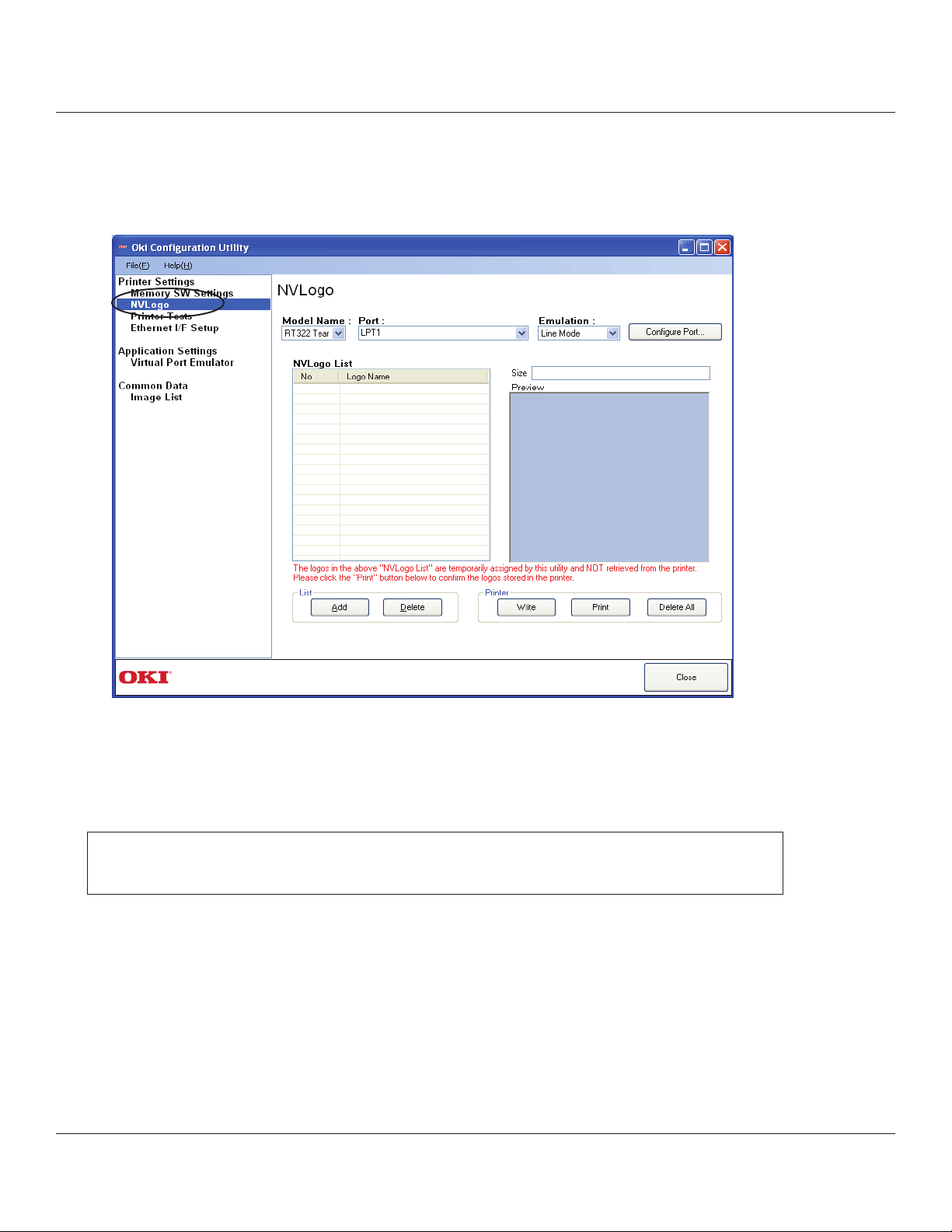
4.1.2 NVLogo
NVLogo is a function for registering image data, selected from data pre-registered in the Image List, to the
printer in order to print them on the top or bottom of the page.
For details about adding image data to the NVLogo list, refer to “4.3.1 Image List”.
To set the print data of NV logos, use the printer driver.
For details, refer to the information in from “3.1.9 Document Top Logo” to “3.1.12 Document Bottom Logo”.
Important: e “NVLogo List” is a list of the data registered in the computer.
To check the images registered in the printer, click the [Print] button.
94
Page 95

1. Click the [Add] button.
2. Select the image that you want to register in the printer, and then click the [Use] button.
95
Page 96

3. e selected graphic data is added to the NVLogo List.
To register multiple images in the printer, repeat steps 1 and 2.
To delete the selected image from the NVLogo List, click the [Delete] button.
4. When you have moved all graphic data to register into the NVLogo List, click the
[Write] button. Data shown in the NVLogo List is written to the printer.
To print all of the NV logo data written to the printer, click the [Print] button. is makes it possible for you
to check all of the image data currently registered in the printer.
To delete all of the NV logo data in the printer, click the [Delete All] button.
The memory capacity for NV logos in this printer is 312 KB.
After clicking the [Write], [Print], or [Delete All] button, the printer will be reset.
Important: By executing [Write], data shown in the “NVLogo List” will be overwritten to
the NV logo memory of the printer
All data previously registered will be deleted.
96
Page 97

4.1.3 Printer Tests
Printer Tests executes the printing function of the printer and prints several samples.
Furthermore, it allows you to conrm that the peripherals work properly.
Test Prints
■ Print Single Byte Characters
Click the [Print] button to print out the 1-byte character table.
■ Print Head Test
Click the [Print] button to execute black solid printing consisting of several lines, and to test the printer
head.
If the black solid printing part of this sample contains white vertical lines, clean the printer head.
Refer to the Hardware Manual to clean the printer head.
Also, if the print can’t be improved even aer cleaning the printer head, please contact your dealer for
advice.
97
Page 98

■ Print Barcodes
Click the [Print] button to print all barcodes supported
■ 2-Color Printing Test
Executes 2-color sample printing.
For 2-color printing, conrm that paper for two colors is set.
The printer performs monochrome printing if this type of paper is not set.
Also, refer to “3.6 Selecting the Print Color” for setup.
Cash Drawer/Peripheral Device
■ Cash Drawer 1 Test
Click the [Test] button to drive cash drawer 1.
is allows you to conrm that cash drawer 1 works properly.
■ Cash Drawer 2 Test
Click the [Test] button to drive cash drawer 2.
is allows you to conrm that cash drawer 2 works properly.
Buzzer/Peripheral Device
■ Buzzer 1 Test
Click the [Test] button to make buzzer 1 sound.
is allows you to conrm that buzzer 1 works properly.
■ Buzzer 2 Test
Click the [Test] button to make buzzer 2 sound.
is allows you to conrm that buzzer 2 works properly.
Important: Buzzers are optional devices.
Note that it is not possible to use buzzers and cash drawers at the same time.
98
Page 99

4.1.4 Ethernet I/F Setup
In Ethernet I/F Setup, settings for the Ethernet interface card connected to the printer can be made using the web browser.
In addition, when using a TCP/IP port with the conguration utility, the TCP/IP port will appear in the Port list by rst
clicking the [Search LAN for Printers] button.
Click the [Search LAN for Printers] button to search the printers connected on your LAN.
If there is an applicable printer, the following dialog box will appear. Click the [OK] button.
99
Page 100

All connected LAN printers are shown in the Printer List on LAN.
Select the printer from the Printer List on LAN and click the [Property] button to display the detailed information of the
current Ethernet interface for the selected printer.
If the printers on the LAN cannot be found, click the [Troubleshooting] button to display “Ethernet I/F setup Trouble-
shooting”.
100
 Loading...