

Page 1

OKIPLATE 904PSIII
OKIPROOF 905PSIII
Maintenance Manual
1999. 3. 4 Rev. 2
40801701TH Rev.2 1 / 122
Page 2

Rev.No. Date Corrected items Person in
No. Page Description of change change
2 1999.3.4 4.1.2 67 Revision of Table E1 Miyazaki
40801701TH Rev.2 2 / 122
2 /
Page 3

Introduction
Introduction
This manual, intended for maintenance personnel, describes the machine maintenance methods in its field.
For handling and operating, see the “Users Manual”. The unit names are referred to as follows.
OKIPLATE 904PSIII .........................OP904
OKIPROOF905PSIII .........................OP905
*Difference of OP904 from OP905 is in
Controller Board (Board Same, only RAM Capacity Different);
LED Head, Mechanism Control Board (Board and ROM Different),
and their print engine blocks are the same.
Note:
40801701TH Rev.2 3 /
• All or any part of the contents is not allowed to be reproduced without permission from the
owner of copyright.
• The contents are subject to change due to improvements in the machine or the description in
the manual itself without notice.
Page 4

Contents
Contents
1. Configuration................................................................................................................... 7
1.1 System Configuration............................................................................................................................7
1.2 Printer Configuration .............................................................................................................................8
1.3 Specification..........................................................................................................................................9
1.4 Printer Indication .................................................................................................................................11
1.4.1 TÜF, CE Label ..............................................................................................................................11
1.4.2 Warning Label ...............................................................................................................................11
2. Operation Description ...................................................................................................12
2.1 Circuit Operation Description ..............................................................................................................14
2.1.1 Controller ......................................................................................................................................14
2.1.1.1 Hardware Configuration ..........................................................................................................14
2.1.1.2 Circuit Operation Description ..................................................................................................15
2.2 Power/Sensor Board ...........................................................................................................................16
2.3 Electrophotographic Process Mechanism...........................................................................................17
2.3.1 Operation Description of Each Process ........................................................................................19
2.4 Paper Jam Sensing.............................................................................................................................26
2.5 Cover Open State ...............................................................................................................................26
2.6 “Toner-low” Detection .........................................................................................................................27
2.7 Paper Size Sensing ............................................................................................................................27
3. Parts Replacement........................................................................................................28
3.1 Parts Replacing Precautions...............................................................................................................28
3.2 Parts layout .........................................................................................................................................30
3.3 Parts Replacing Methods ....................................................................................................................35
3.3.1 Face-up Stacker Assy...................................................................................................................36
3.3.2 Contact Assy.................................................................................................................................37
3.3.3 DC Fan Motor ...............................................................................................................................38
3.3.4 Operator Panel Assy.....................................................................................................................39
3.3.5 SRA-PCB .....................................................................................................................................40
3.3.6 Stacker Cover Assy, DC12V Fan Motor, Damper Arm .................................................................41
3.3.7 Damper .........................................................................................................................................43
3.3.8 Eject Roller Assy ...........................................................................................................................44
3.3.9 Separation Piece (Sticky)..............................................................................................................45
3.3.10 FF Roller Assy, Bearing F ...........................................................................................................48
3.3.11 Paper Feed Motor .......................................................................................................................49
3.3.12 Resister Roller Assy....................................................................................................................50
3.3.13 Main Motor, Resister Motor.........................................................................................................51
3.3.14 Fuser Assy ..................................................................................................................................53
3.3.15 Fusing guide ...............................................................................................................................54
3.3.16 Back-up Roller ............................................................................................................................55
3.3.17 Hopping Roller Assy ...................................................................................................................56
3.3.18 Power Supply..............................................................................................................................57
3.3.19 Paper End Lever .........................................................................................................................58
3.3.20 Detector Spring, LLSW-PCB (First Tray) ....................................................................................59
3.3.21 LED Head ...................................................................................................................................60
40801701TH Rev.2 4 /
Page 5

Contents
3.3.22 Paper Cassette ...........................................................................................................................61
3.3.23 Transfer Roller, TR Gear, TR Bearing ........................................................................................62
3.3.24 Feeding Roller.............................................................................................................................63
3.3.25 Detector Spring, LLSW-PCB (Second Tray)...............................................................................64
4. Adjustment ....................................................................................................................65
4.1 LED Head Driving Time Set-up...........................................................................................................65
4.1.1 Outline of Set-up Procedure .........................................................................................................66
4.1.2 Driving Time Set-up ......................................................................................................................67
4.2 Fuser Counter Reset (only OP905) ....................................................................................................69
5. Routine Maintenance ....................................................................................................70
5.1 Routine Replacement Parts ................................................................................................................70
5.2 Cleaning..............................................................................................................................................70
5.2.1 LED Lens Array Clearning ...........................................................................................................70
6. Troubleshooting Produre...............................................................................................72
6.1 Prior to Repairing ................................................................................................................................72
6.2 Check Points prior to Handling Imperfect Image ................................................................................72
6.3 Precautions on Handling Imperfect Image..........................................................................................72
6.4 Preparation for Troubleshooting .........................................................................................................73
6.5 Troubleshooting Methods ...................................................................................................................73
6.5.1 LCD Status Message List .............................................................................................................73
6.5.2 LCD Message Troubleshooting ....................................................................................................77
6.5.3 Imperfect Image Troubleshooting .................................................................................................85
6.5.4 Manual Feed Hopper Assy Opening/Closing Troubleshooting .....................................................94
7. Connection Diagram .....................................................................................................95
7.1 Connection Diagram ...........................................................................................................................95
7.2 Board Layout.......................................................................................................................................99
8. Interface Specification.................................................................................................104
8.1 Interface Specification.......................................................................................................................104
8.1.1 Centronics Interface Specification ..............................................................................................104
8.1.2 Centronics Interface Connector and Cable.................................................................................104
8.1.3 Centronics Interface Level ..........................................................................................................104
8.1.4 Centronics Interface Circuit.........................................................................................................105
8.2 RS232C Interface Specification ........................................................................................................107
8.2.1 RS232C Interface General..........................................................................................................107
8.2.2 RS232C Interface Connector and Cable ....................................................................................107
8.2.3 RS232C Interface Level..............................................................................................................107
8.2.4 RS232C Interface Circuit ............................................................................................................108
8.2.5 RS232 Interface Signal ...............................................................................................................108
8.3 RS422A Interface Specification ........................................................................................................109
8.3.1 RS422A Interface General..........................................................................................................109
8.3.2 RS422A Interface Connector and Cable.....................................................................................109
8.3.3 RS422A Interface Signal.............................................................................................................110
8.4 AppleTalk® Interface Specification ....................................................................................................111
8.4.1 AppleTalk® Interface General.....................................................................................................111
8.4.2 AppleTalk® Interface and Connector...........................................................................................111
8.4.3 AppleTalk® Interface Level ..........................................................................................................111
40801701TH Rev.2 5 /
Page 6

Contents
8.4.4 AppleTalk® Interface Circuit ........................................................................................................111
8.4.5 AppleTalk® Interface Signal ........................................................................................................112
8.5 Parallel Interface Specification..........................................................................................................113
8.5.1 Electrical Conditions ...................................................................................................................113
8.5.2 Timing Chart ...............................................................................................................................114
9. Component Parts List..................................................................................................115
40801701TH Rev.2 6 /
Page 7
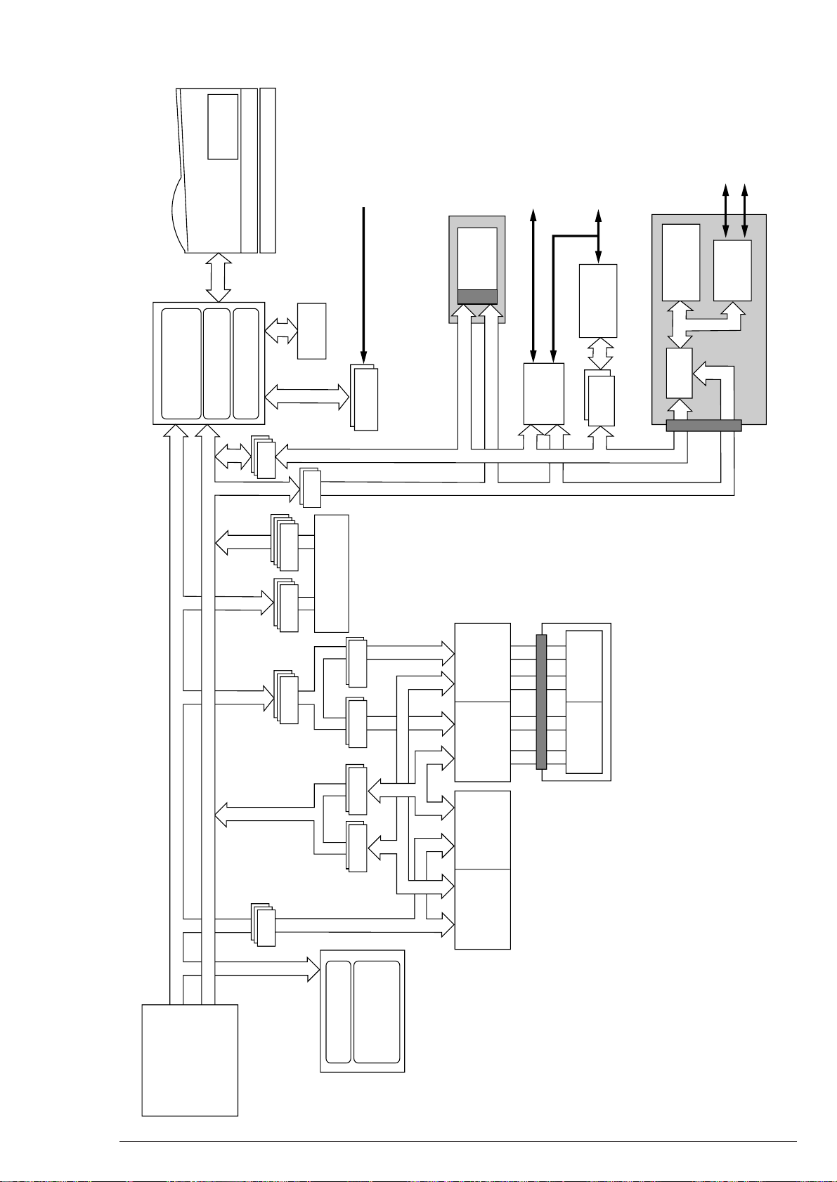
1. Configuration
Controller Block
Centronics
RS232C
Appletalk
RS422A
Ethertalk
Main Control Board
1750MB HDD
Expansion RAM
Board
16MB
Operator
Panel
Engine Block
136 Roman Fonts
EtherTalk
Board
100/10
Base-TX
Engine Control Board
OP905 : Engine
(A3/1200dpi/10ppm)
OP904 : Engine
(A3/600dpi/12ppm)
First Tray
Front Feeder
Second Tray
Power Supply
AC IN
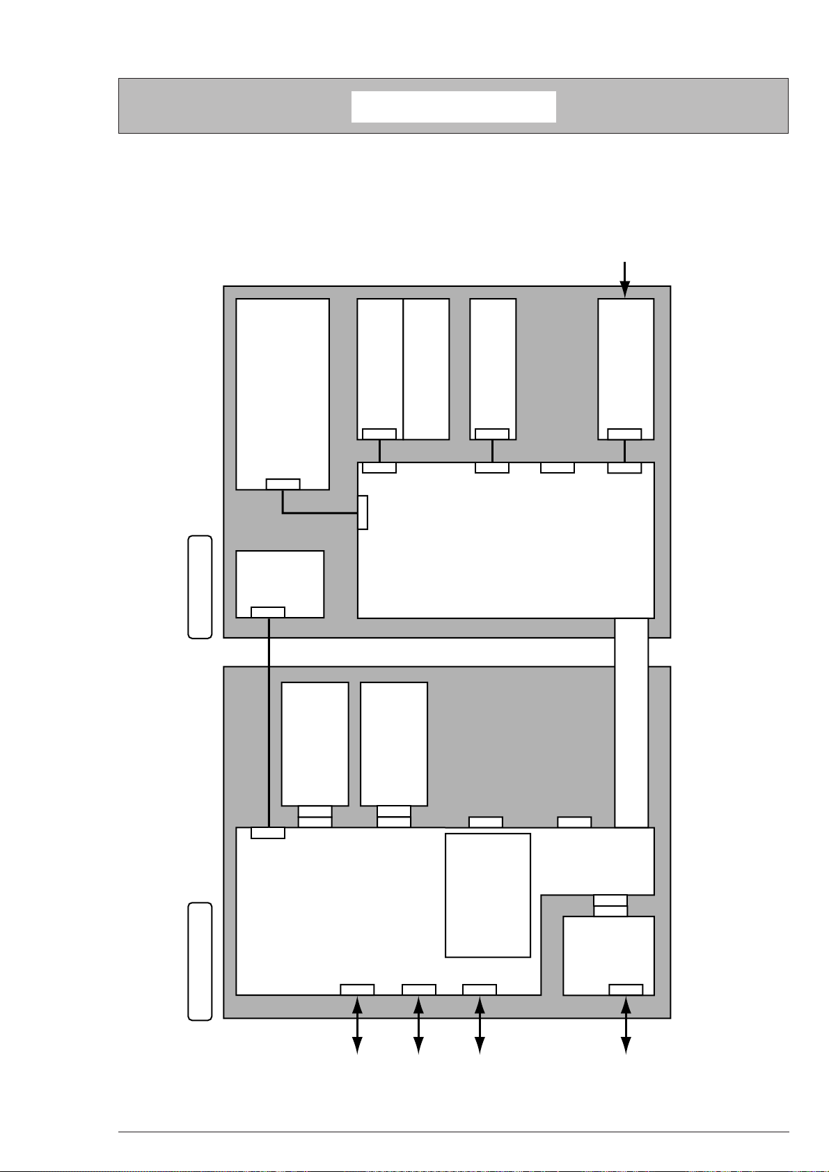
1.1 System Configuration
This unit consists of a control block and an engine block as standard. (See Figure 1-1.)
1. Configuration
Figure 1-1
40801701TH Rev.2 7 /
Page 8
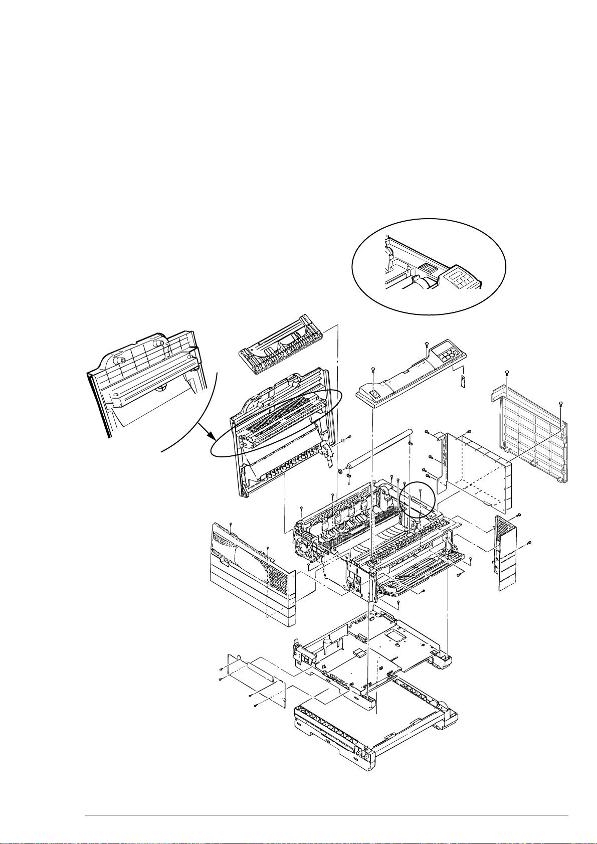
1.2 Printer Configuration
The internal part of the printer consists of the following parts.
• Electrophotographic Processor
• Paper Feeder
• Control Block
• Operator Panel
• Power-supply Unit
Figure 1-2 shows the printer unit configuration.
Only in ML905, the LED head and the circled cover parts differ from those of others.
OP905
1. Configuration
OP905
Figure 1-2
40801701TH Rev.2 8 /
Page 9
1.3 Specification
(1) Type Desk Top Type
(2) External Dimensions Height 317mm
(Excluding protrusion) Width 498mm
Depth 430
(3) Weight 30kg (OP904), 28kg (OP905)
(4) Development Method Dry Electrophotography
Exposure Method LED Head Method
(5) Paper
1. Configuration
Type Size Thickness Texture
Plain
Paper
Thick
Paper
Special
Paper
105 x 148mm
to 328 x 453mm
148 x 210mm
to 328 x 453mm
148 x 210mm
to 328 x 453mm
105 x 148mm
to 328 x 453mm
297 x 488mm
to 340 x 505mm
20lb to 28lb
28lb to 32lb
Appointment paper Vertical
Vertical
Vertical
Vertical
Paper Feed Method
First
Tray
Second
Tray
Front
Feeder
Remark
Use Face-up
Stacker.
Use Face-up
Stacker.
(6) Printing Speed First Printing 16 sec
Consecutive Printing 12 copies/min. (A4 Horizontal)
Warm-up Time 2 min
(AC230V, Ambient Temperature 25°C)
(7) Paper Feed Method Automatic Paper Feed Method, Manual Feed Method
(8) Paper Delivery Method Face-down, Face-up
(9) Resolution 600 x 600 dot/inch (OKIPLATE 904PSIII)
1200 x 1200 dot/inch (OKIPLATE 904PSIII)
(10) Power Input AC230V
(11) Power Consumption Maximum Average
During operation 1100W or less Approx. 400W
Heater off 45W
40801701TH Rev.2 9 /
Page 10

(12) Temperature, Humidity
Temperature Humidity
During
operation
10 to 32°C 20 to 80%RH (Relative Humidity)
In storage -23 to 43°C 10 to 90%RH (Relative Humidity)
No condensation detected.
1. Configuration
Note:
In storage, a packaged condition is required and the period shall
not exceed one year.
(13) Noise During operation 53dB(A) or less
In standby time 45dB(A) or less
(14) Consumables Life Toner Cartridge Approx. 5,000 copies
(A4 5% duty consecutive printing. Except
for the life of the first toner cartridge to be set
to a new drum.)
Drum Cartridge Approx. 10,000 copies
(A4 consecutive printing)
40801701TH Rev.2 10 /
Page 11
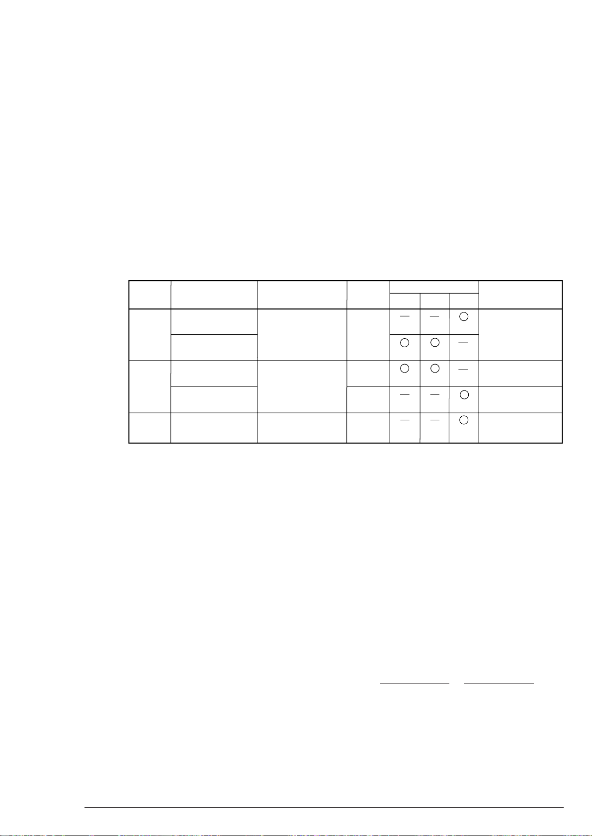
1.4 Printer Indication
1.4.1 TÜF, CE Label
The following parts of the printer are labeled TÜF, CE.
Such as
1. Configuration
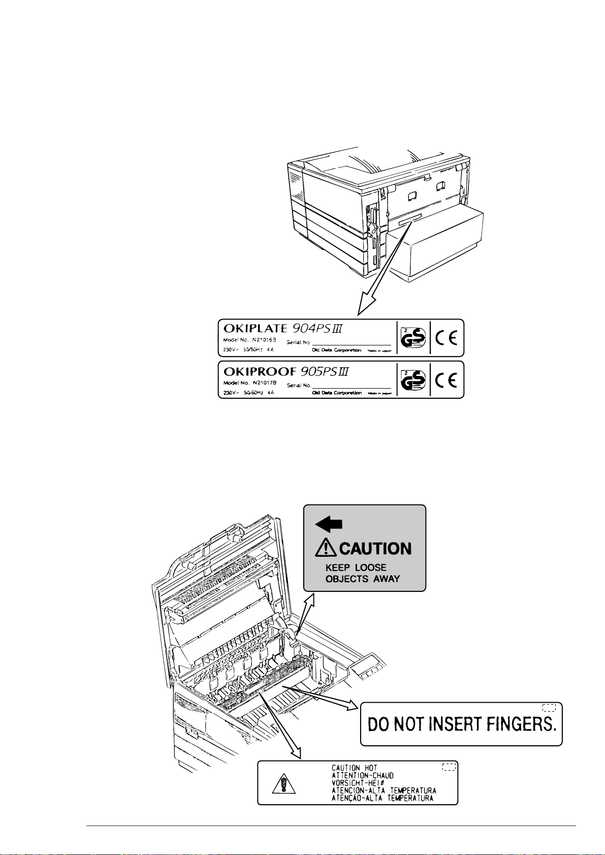
1.4.2 Warning Label
Warning indications are given at the places hazardous to human bodies.
Pay attention to the warnings and take precautions carefully while at work.
MN
40801701TH Rev.2 11 /
Page 12

2. Operation Description
2. Operation Description
This unit consists of a control board, a power/sensor board, an operator panel, and an electrophotographic
process mechanism. Print data is received from the host interface. They are decrypted and edited before
sequential storing in memory. When editing one page of data is finished, font memory referring is performed
and bit images are generated in the same memory. Concurrently, the bit images are from time to time transferred
to the LED head by dot line and printed on paper by the electrophotographic process mechanism.
The operator panel operates the device and displays the status.
Figure 2-1 shows the block diagram of the device.
40801701TH Rev.2 12 /
Page 13
SIMM SIMM
ABT373x2 ABT373x2
(Even) (Odd)
Regident DRAM
(16Mbitx8)
(904/905)
(Even) (Odd)
CODE ROM
512K word x 16
x 2
CODE ROM
512K word x 16
x 2
F244x3
F158x3
FCT16543
x2
FCT16543
x2
F245x3
F373x3
F244x2
F244x4
FONT ROM
ATC1284x2
EEPROM
3.5" HDD
(EIDE)
RS232C I/F
Centro I/F
12PPM PRINT UNIT
A3 / 600dpi :OP904
A3 / 1200dpi :OP905
AppleTalk/RS422I/F
100Base-TX
10Base-TX
Address BUS
Data BUS
Command ROM
Address Generation
DRAM Controller,
Refresh, Access
Sequencer
NEC G/A 240pin
uPD65806GN-136-LMU
LS374
85C30
SCSI
NEC G/A 240pin
uPD68806GN-136-LMU
I/O Access Controller
Engine I/F(VIDEOI/F)
Operator Panel,
Command I/F
Operator Panel
Mechanism
Control
POWER UNIT
First Tray 250 sheets
Second Tray 250 sheets
Peripheral Data BUS
NIC Controller
MPD70236
ROM 1MByte
RAM 512KByte
Dualport
RAM
Z80181
ROM 512Kbit
RAM 256Kbit
Am29040-50KC
(Clock 50MHz)
Redident SIMM
16M Byte x 2 (905)
8M Byte x 2
2. Operation Description
Figure 2-1 Block Diagram
40801701TH Rev.2 13 /
Page 14

2. Operation Description
2.1 Circuit Operation Description
2.1.1 Controller
The main control board of the OP900’s controller is a printer controller designed for a postscript. The controller
has a high-performance RISC processor Am29040, 32-megabyte RAM (64 megabytes for OP905), ROM, a
RS-232C port, an AppleTalk TM port, a parallel transmission port, a printer unit interface port, and 512-byte
EEPROM.
This controller is designed so as to connect to an OKI A3 engine and has an OKI standard printer interface.
In this controller, PostScript is used to print images read in a “Text,” a “Graphics,” and a scanner. All the print
files which the controller handles are generated by PostScript programs. PostScript enables graphics image
processes, general program flow control, and data structures.
2.1.1.1 Hardware Configuration
The OP904 and OP905 controllers consist of the following circuit blocks in rough.
(1) RISC Processor
(2) RAM
(3) Program ROM
(4) Font ROM
(5) Printer Interface
(6) Communication Interface
(7) Operator Panel Interface
40801701TH Rev.2 14 /
Page 15

2.1.1.2 Circuit Operation Description
(1) CPU Peripherals
Element Used : AMD-made Am29040-50KC
CPU Operation Clock : 50MHz
Timer : Timer with built-in CPU is used.
(2) Memory Peripherals
(a) RAM
Element Used : Equivalent to HM514400ZP-8
Access : Operation in “High Speed Page” Mode
RAS Inactive only in performing Miss Hit or Refresh.
Refresh Control : CAS before RAS
1024 Refresh/Approx. 10.49mS
Controlling by G/A #1
3 wait (in Miss Hit)
0 wait (in Burust Access)
2. Operation Description
OP905 and OP904 have eight banks of tatal 64-megabyte storage and four banks of total 32megabyte storage, at eight megabytes per bank unit, respectively.
(b) Program ROM
Element Used : Equivalent to 27C852-12
Access time 120nS or less is required.
0 wait (in Burust Access)
0 wait or 1+1 wait (except for Burust)
A 32-bit width or one word is generated with two units because the program ROM is 16-bit wide.
(c) Font ROM
Element Used OP904 : 32M-MASK x 2 + 8M-MASK x 2
OP905 : 32M-MASK x 2 + 8M-MASK x 2
(d) Resident EEPROM
Element Used : Equivalent to X2404(Xicor)
Capacity : 8bit x 256word x 2page
EEPROM is used for data memorizing as fixed memory. Batteries are not required.
Menu set-up values and other data are borne in memory.
40801701TH Rev.2 15 /
Page 16
2. Operation Description
Sensor
Inlet Sensor 1
Inlet Sensor 2
Inlet Sensor 3
Paper Sensor
Outlet Sensor
Paper End Sensor
Toner Sensor
Functions
When paper is loaded, the leading part of paper is detected to
obtain a supervision timing for switching from a hopping operation to a feeding operation. Also paper feeding and its size
are monitored accordong to paper arrival and running time.
Paper Width Check
Paper Width Check
The leading part of paper is detected.
Paper feeding is monitored.
Paper feeding and its size are monitored based on paper
arrival and running time.
The paper end is detected.
Toner-low is detected.
Sensing State
ON : Paper exists.
OFF : No paper exists.
ON : A4 size or larger
OFF : A4 size or smaller
ON : B4 size or larger
OFF : B4 size or smaller
ON : Paper exists.
OFF : No paper exists.
ON : Paper exists.
OFF : No paper exists.
ON : Paper exists.
OFF : No paper exists.
ON LONG : Toner is low.
ON SHORT : Toner exists.
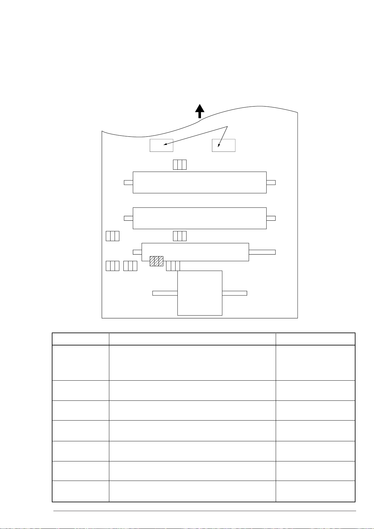
2.2 Power/Sensor Board
This board consists of an AC filter circuit, a low voltage power supply circuit which supplies power to the control
system, a high voltage power supply circuit which supplies power to the electrophotographic process system, a
heater driver circuit, and a photosensor for the paper feed system and toner detection use.
Figure 2-2 shows the sensor layout.
Paper Feeding Direction
Eject Roller
Outlet Sensor
Heat Roller
Transfer Roller
Paper Sensor
Toner
Sensor
Inlet
Sensor 3
Paper End
Sensor
Inlet
Sensor 2
Resist Roller
Inlet Sensor 1
Hopping Roller
Figure 2-2 Sensor Layout
40801701TH Rev.2 16 /
Page 17

2.3 Electrophotographic Process Mechanism
(1) Electrophotographic Process
The following is the outline of the electrophotographic process.
1 Charging
Applying DC voltage to the CH roller charges the surface of the OPC drum evenly in negative.
2 Exposure
Light from the LED head is directed onto the surface of the negatively charged OPC drum. The
emitted parts of the drum surface attenuates in the surface potential and electrostatic latent images
are generated according to image signals.
3 Development and Recovery of Residual Toner
Negatively charged toner contacts the OPC drum. With static, the toner is fixed on the electrostatic
latent images on the drum and changed into its visible images.
At the same time, residual toner on the drum is drawn to the developing roller with static.
2. Operation Description
4 Transfer
The toner is drawn on paper with static by laying the paper on the OPC drum surface and applying
a positive charge opposite to the toner polarity to the back of the paper by the transfer roller.
5 Cleaning
The cleaning roller draws the residual toner on the OPC drum with static after the transfer and then
returns it to the drum.
6 Fusing
Applying heat and pressure fuses post-transfer unfixed toner images on the paper.
40801701TH Rev.2 17 /
Page 18

2. Operation Description
(2) Paper Feeding Motor
48-step/rotation pulse motor. Two-phase excited driving is made based on signals from the control
board.
The hopping roller for the first tray and the front feed roller are driven via two one-way clutches
according to each motor rotating direction.
(3) Resister Roller
48-step/rotation pulse motor. Two-phase excited driving based on signals from the control board
drives the resister roller.
(4) Drum Motor
96-step/rotation pulse motor. Two-phase excited driving based on signals from the cotrol board
changes into motive power of the mechanism.
(5) LED Head
The shift/latch resister receives images by dot line from the control board and 76,800 (600dpi Head),
15,360 (1200dpi Head) of LEDs are driven to emit onto the image drum.
(6) Fuser
A heater, a heat roller, a thermistor, and a thermostat constitute the fuser.
The power/sensor board supplies AC voltage to the heater based on signals (HRATON) from the
control board to heat the heat roller, while the control board supervises the heat roller temperature via
the thermistor and sets on/off the heater AC voltage supply to keep the even temperature.
An extraordinary rise in temperature of the heat roller causes the thermostat in the heater voltage
supply circuit on and cuts off the AC voltage supply by force.
40801701TH Rev.2 18 /
Page 19
2.3.1 Operation Description of Each Process
• Hopping
Hopping switches between the first tray and the front feeder paper feeding by the following mechanism:
Idle Gear A
One-way Clutch Gear B
2. Operation Description
Paper Feed Motor
(Pulse Motor)
a
b
Hopping Roller
(Front Feeder)
FF Plate
Hopping Roller
(First Tray)
(1) Paper Feeding from First Tray
Idle Gear B
Resister Roller
One-way Clutch Gear A
Figure A
1 Figure A shows that the paper feed motor rotates in the “a” direction (CW direction) to drive the
hopping roller and paper is fed until the inlet sensor is on.
While the front feeder gear is also revolving then, the FF roller is not turned by the one-way bearing.
2 After the paper turns the inlet sensor on, feeding a certain quantity of further paper runs the paper
against the resister roller. (This corrects a skew of paper.)
40801701TH Rev.2 19 /
Page 20

(2) Paper Feeding from Second Tray
Idle Roller
Planet Gear
Paper
Feeding Gear
(One-way Clutch Gear)
Feeding Roller
Hopping Gear
(One-way Clutch Gear)
Hopping Roller
Paper Feed Motor
Idle Gear
b"
a"
a'
b
a
2. Operation Description
1 Hopping
The pulse motor rotates in the “a” direction (CW direction) to drive the hopping roller and feeding
roller.
2 Feeding
When hopping is finished, the pulse motor rotates in the “b” direction (CCW direction) to drive the
feeding roller. While the hopping gear is also revolving then, the hopping roller is not being turned
by the one-way bearing.
40801701TH Rev.2 20 /
Page 21

2. Operation Description
(3) Paper Feeding from Front Feeder
1 When the printer is turned on, the front feeder takes up a position to lower the FF plate.
(its home position).
2 Figure A shows that the one-way clutch gear B revolves via the idle gear to turn the FF roller and FF
cam when the paper feed motor rotates in the “b” direction (CCW direction).
3 Turning the FF cam releases the FF plate from the FF plate pressing release lever, then the FF
plate is raised by the spring. Paper on the FF plate is pressed against the FF roller. The FF roller
feeds out the paper pressed. It continues until the inlet sensor is on, and a certain further quantity
is moved forward to run the paper against the resister roller. (This corrects a skew of paper.)
4 While the FF roller feeds the paper, the FF cam turns and presses down the FF plate. When the FF
plate lowers in its full, the release lever lies on the FF plate to keep the plate uchanged even if the
plate is disconnected from the FF cam.
5 Feeding the paper by the resister roller turns the FF roller by rubbing against the paper. This
turning power drives the shaft and it continues until the FF cam touches the release lever to obtain
a standby state for the next hopping.
The one-way bearing is built into the FF roller boss. After the cam touches the release lever, the
one-way bearing runs idle so as not to turn the shaft.
40801701TH Rev.2 21 /
Page 22
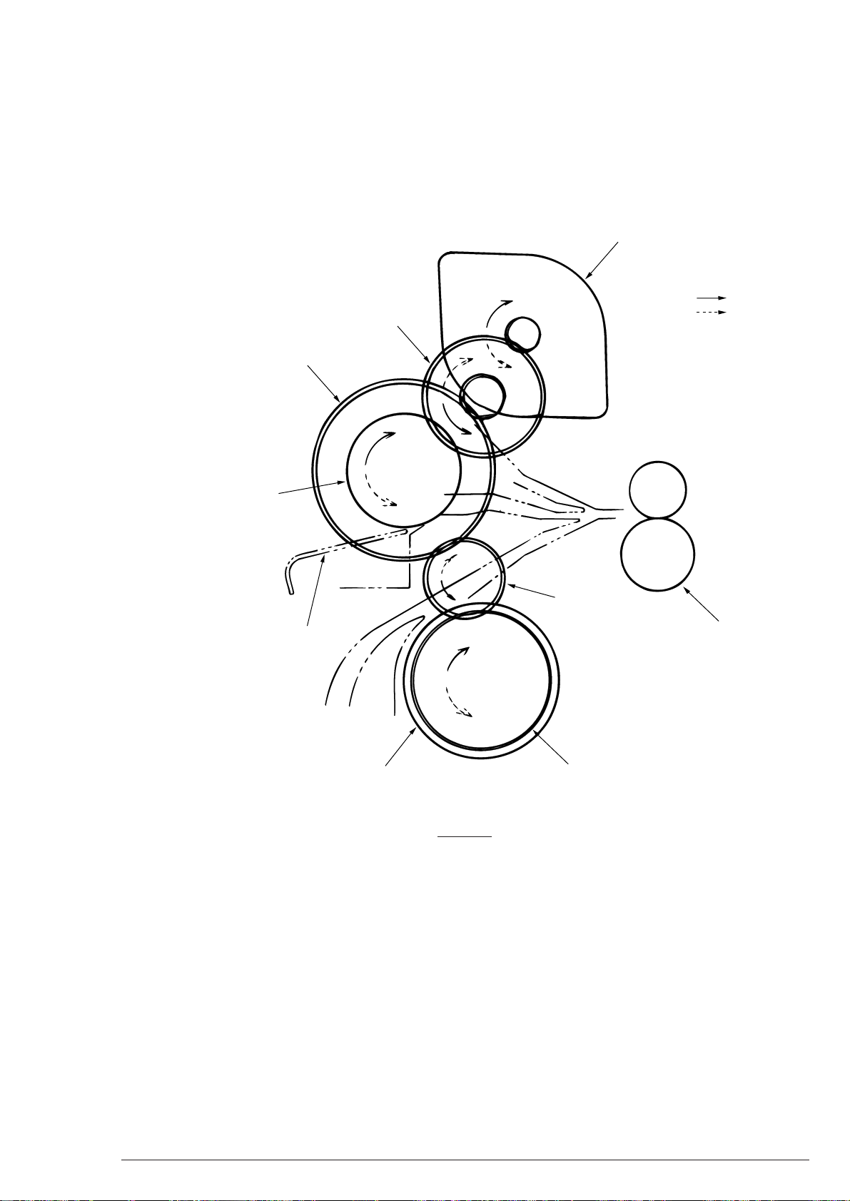
• Feeding
g
2. Operation Description
OPC Drum
Paper Sensor
Transfer Roller
Pulse Motor
Paper
Resister Roller
Hoppin
Roller
1 After the hopping is finished, the resister motor rotates to drive the resister roller and paper is fed
until the paper sensor is on.
2 Further feeding is synchronized with printing data.
40801701TH Rev.2 22 /
Page 23
2. Operation Description
Power
Supply
OPC Drum
Charging Roller
Power
Supply
OPC Drum
Charging Roller
OPC Drum
LED Head
LED Head
Paper
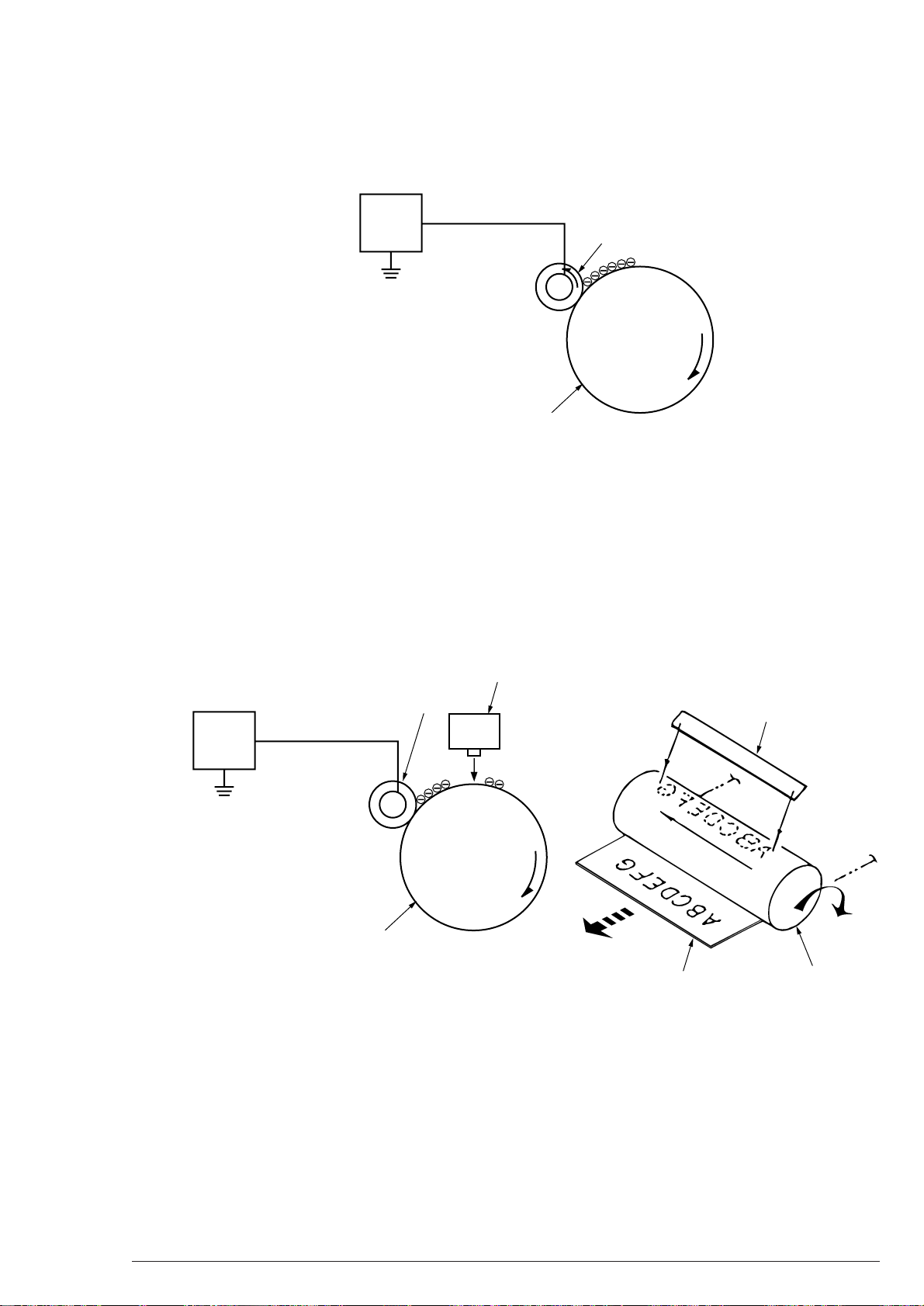
(1) Charging
Charging is processed by applying DC voltage to the charging roller contacting the OPC drum surface.
(2) Exposure
Light from the LED head is directed onto the surface of the negatively charged OPC drum. The
potential of the emitted parts of the OPC drum attenuates and electrostatic latent images are generated
according to image signals.
40801701TH Rev.2 23 /
Page 24
2. Operation Description
OPC Drum
Transfer Roller
Paper
Power
Supply
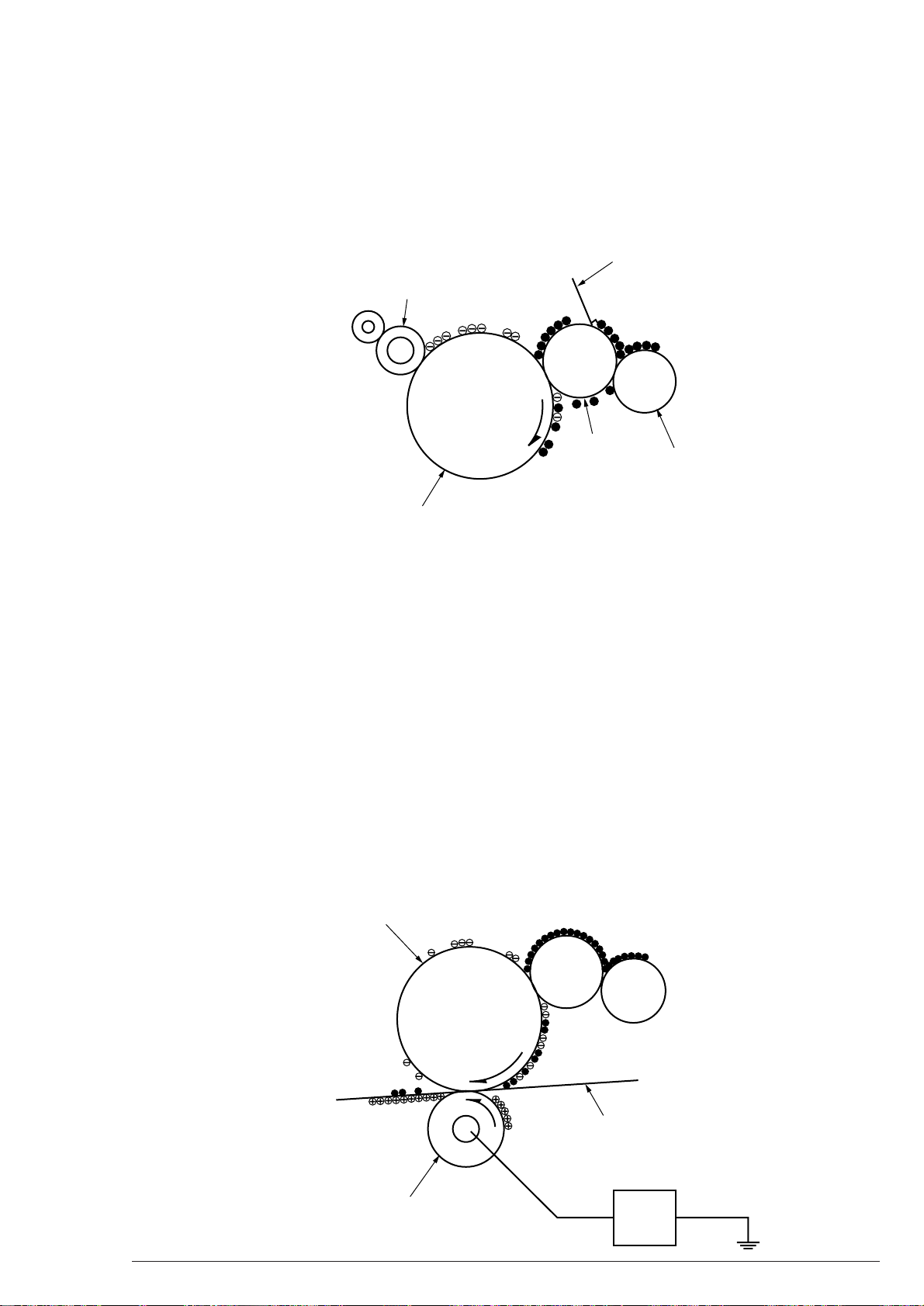
(3) Development
Fixing toner on electrostatic latent images on the OPC drum surface changes the toner to its visible
images. Development is processed in the contact parts between the OPC drum and the developing
roller.
1 The sponge roller fixes toner on the developing roller. The toner is charged negatively then.
Developing Blade
Charging Roller
Developing
Roller
OPC Drum
Sponge Roller
2 The toner on the developing roller is shaven by the developing blade to make a thin layer of the
toner on the surface of the developing roller.
3 Fixing the toner to the exposed parts of the OPC drum makes electrostatic latent images visible in
the contact parts between the OPC drum and the developing roller.
(4) Transfer
The transfer roller is made of a conductive sponge material and arranged so that paper and the OPC
drum surface are well close together.
A positive charge opposite to the toner polarity (negative) is applied to the back of paper by the
transfer roller, laying the paper on the OPC drum surface.
Applying high voltage from the power supply (positive) to the transfer roller moves a positive charge
induced on the roller surface to the paper side in the contact parts of the transfer roller.
A positive charge on the back of the paper moves the negative toner on the OPC drum surface to the
upside of the paper. Transfering to the paper is performed by this.
40801701TH Rev.2 24 /
Page 25
2. Operation Description
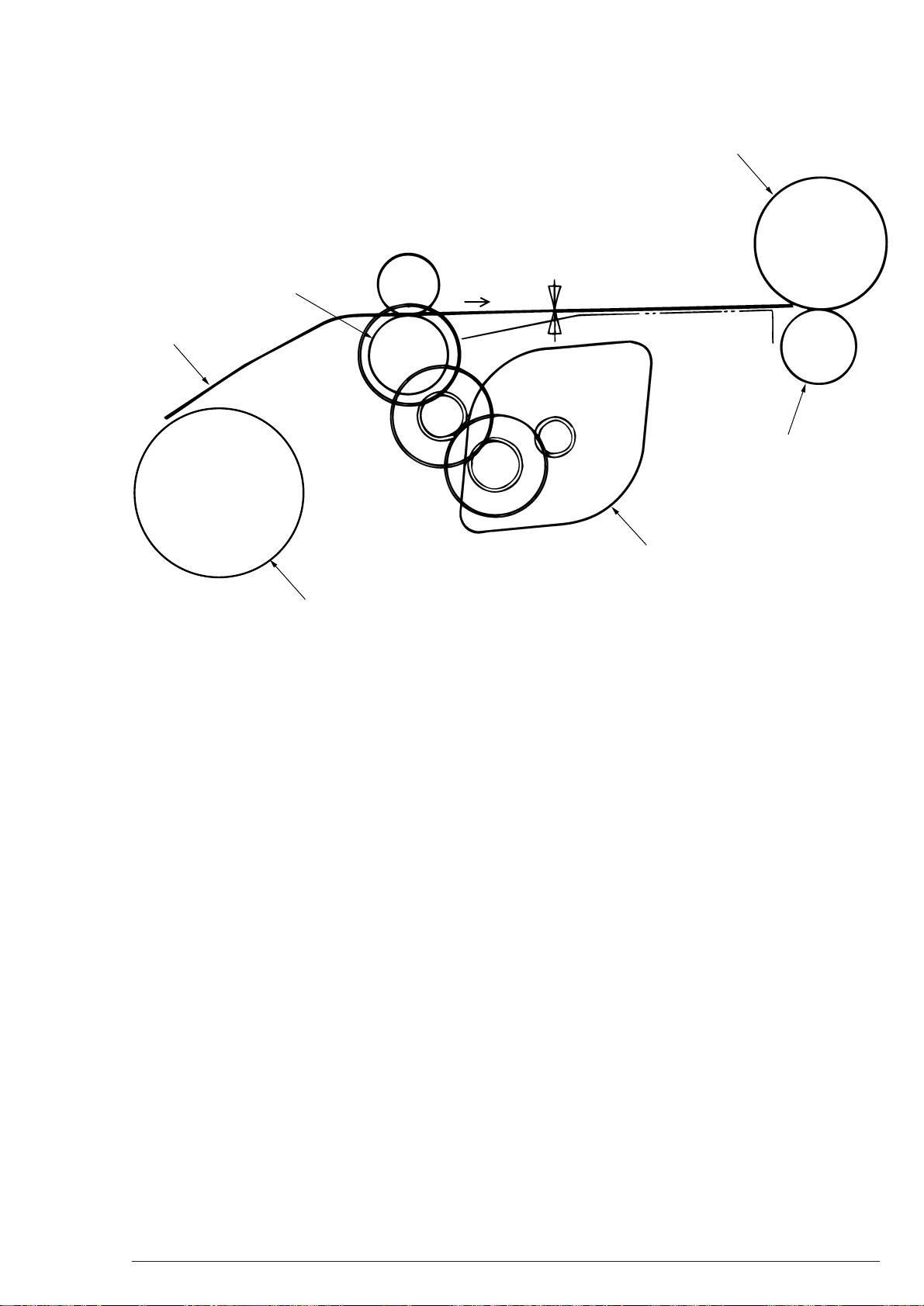
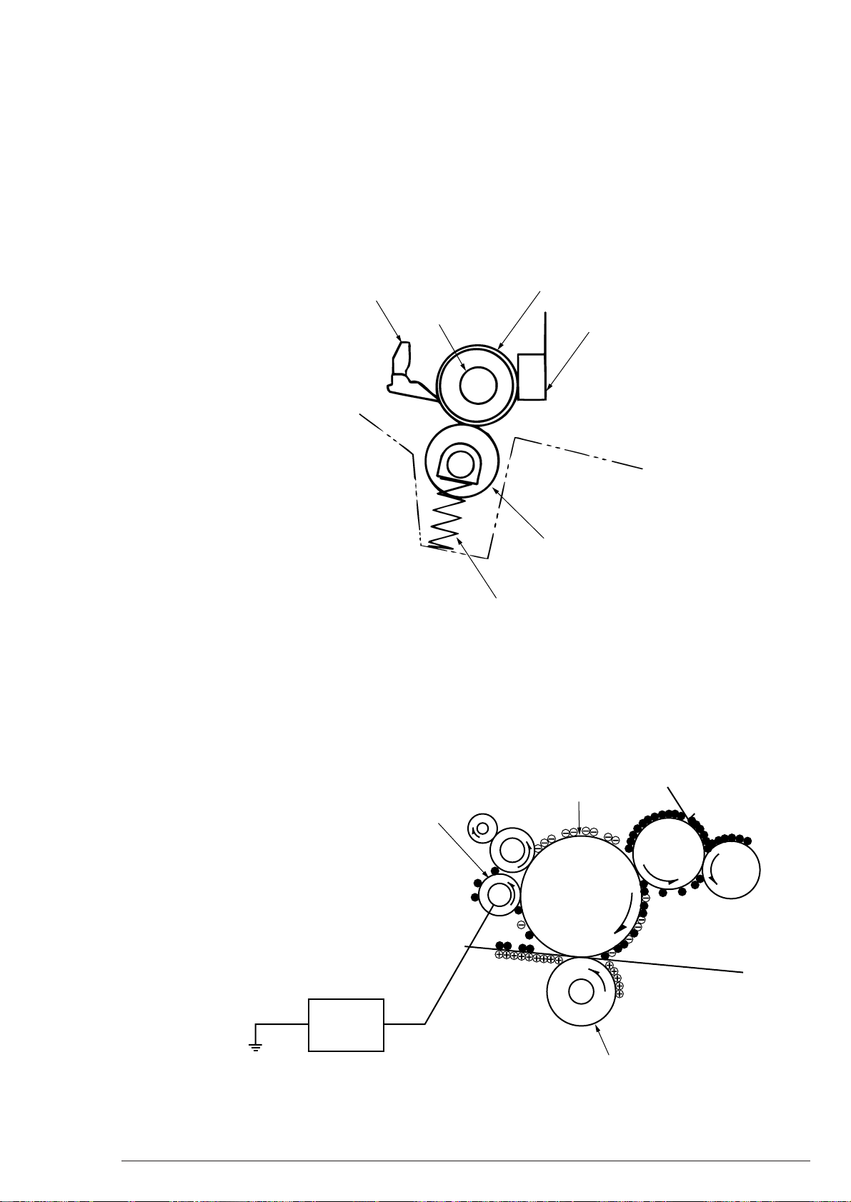
(5) Fusing
When passing between the heat roller and back-up roller, post-transfer unfixed toner images fuse on
the paper with heat and pressure.
A 800W of heater (halogen lamp) is inserted into the internal part of the teflon-coated heat roller to
heat the heat roller. Also a thermistor moves over the surface of the heat roller and controls the
temperature to keep it constant. In addition, thermostat, which is open for the duration of a temperature
rise to break voltage supply to the heater, is attached for safety.
The pressure springs on both sides press the back-up roller.
Separation claw
Heater
Pressure Spring
Heater roller
Thermistor
Back-up roller
(6) Cleaning
After the transfer, the cleaning roller draws the non-transferred residual toner on the OPC drum with
static and then returns it to the OPC drum.
Also the CH cleaner negatively charges positive toner on the charging roller to return the toner from
the charging roller to the OPC drum.
OPC Drum
Cleaning Roller
Power
supply
40801701TH Rev.2 25 /
+DC
Transfer Roller
Page 26

2. Operation Description
2.4 Paper Jam Sensing
Paper states are monitored when power is turned on and while printing. If any one of the following events
occurs, the print processing is suspended as a paper jam. Removing the jammed paper (Cover open/Remove/
Cover close) processes recovery printing.
Error Error Condition
Paper Input Jam
"PAPER LOAD JAM"
Paper Feed Jam
"PAPER FEED JAM"
Paper Outlet Jam
"EJECTION JAM"
Paper Size Error
"PAPER SIZE ERROR"
•
The leading part of paper does not reach Inlet Sensor after three times of
hopping at paper loading.
•
Paper exists on Inlet Sensor or Paper Sensor when power is turned on.
•
The leading part of paper does not reach Paper Sensor within a certain
time after passing Inlet Sensor.
•
The leading part of paper does not reach Ejection Sensor within a certain time after passing Paper Sensor.
•
Paper does not pass Inlet Sensor within the specified time.
•
Paper exists on Outlet Sensor when power is turned on.
•
Paper does not pass Outlet Sensor within the specified time.
•
Inlet Sensor and Outlet Sensor monitor the paper running time each and
detect a size difference of 45mm or more between paper used and the
tray-set paper.
•
A paper width detected by Paper Width Sensor is different from the trayset one. (Paper Width Sensor detection is applicable to the paper size
B4 or larger, and A4 or smaller.)
2.5 Cover Open State
Opening the stacker cover turns the cover opening microswitch on the power/sensor board off and cuts off 38V
supply to a high voltage supply to stop all high voltage lines output.
Concurrently, CVOPN signals inform the control board of the switching state and cover open processing is
performed.
40801701TH Rev.2 26 /
Page 27
2. Operation Description
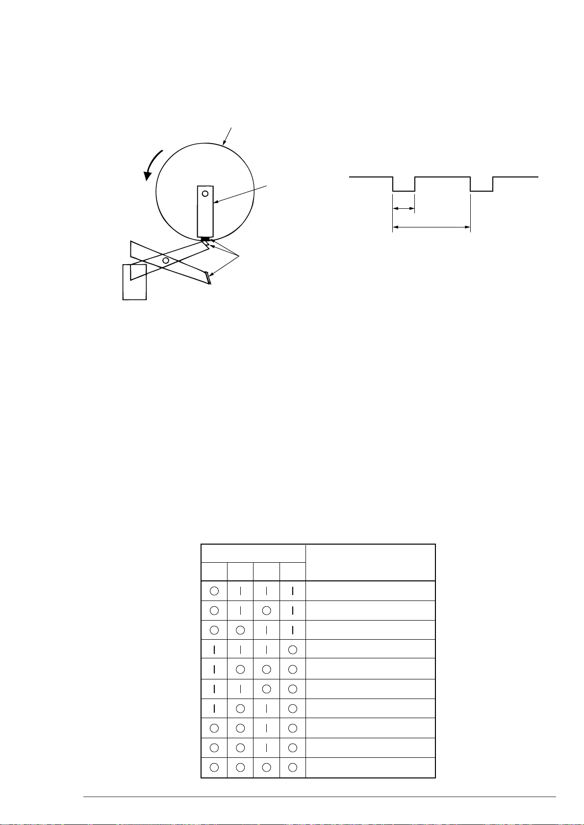
2.6 “Toner-low” Detection
When toner is low, the lever reaches the magnet position of the toner sensor soon. In a tonerful state, the lever
moves almost as fast as the stirring roller turns.
Internal Stirring Roller of EP
Lever
Magnet
Toner Sensor
TNRSNS
On Off
t
T
Toner-low State : t>T/4
Tonerful State : t<T/4
Toner Replacing Alarm and Toner Life Alarm Detection Sequence
(1) Two consecutive toner-low states give a toner replacing alarm.
(2) Processing 100 pages of printing at toner replacing alarming gives a toner life alarm.
(3) Two consecutive tonerful states in toner replacing alarming cancel a toner replacing alarm.
Note:
If the drum motor is not rotating, the toner sensor monitoring is not executed.
2.7 Paper Size Sensing
T=6.1 sec
Four tab pieces are driven according to setting positions of the paper guide, through the cam linked with the
paper guide of the paper cassette.
When the paper cassette is attached to the printer, the microswitch detects a state of tab pieces to recognize a
paper size.
Microswitchin Prosess
Paper Size
SW1 SW2 SW3 SW4
Letter
Executive
A4
Legal 14
B5 Y
A5
B4
A3
A3 Nobi
A4 Y
40801701TH Rev.2 27 /
Page 28
3. Parts Replacement
Disconnect
Reconnect
OFF
ON
3. Parts Replacement
This section describes the procedure for replacing the parts, assemblies, and units in the field. Although the
replacing procedure is for detaching, the reverse procedure must be used for attaching them.
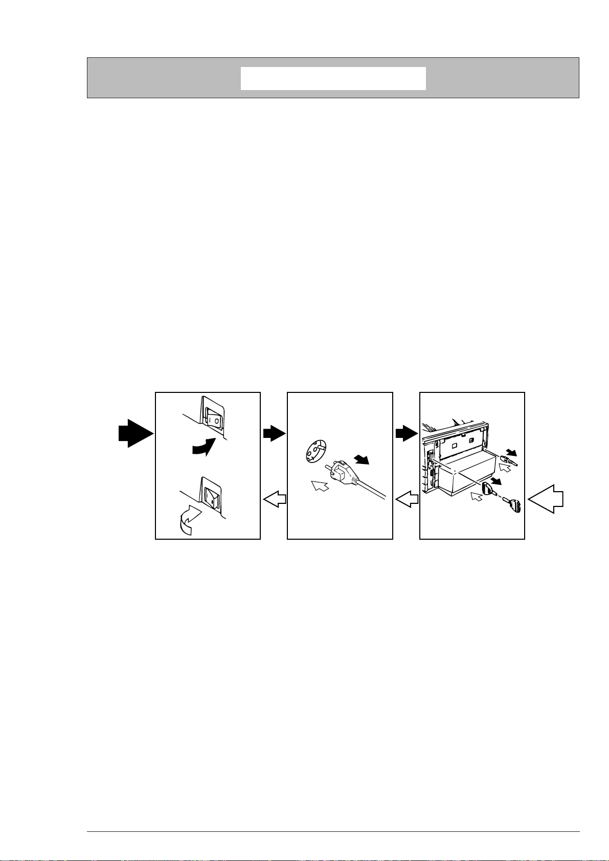
3.1 Parts Replacing Precautions
(1) Never fail to disconnect the AC cable and the interface cable before replacing the parts.
(a) Detach the AC cable by using the following procedure.
1 Switch the POWER of the printer off to “O”.
2 Pull the AC inlet plug of the AC cable out of the AC receptacle.
3 Pull the AC cable and the interface cable out of the printer.
(b) To re-connect to the printer, use the following procedure.
1 Connect the AC cable and the interface cable to the printer.
2 Connect the AC inlet plug to the AC receptacle.
3 Switch the POWER of the printer on to “I”.
(2) Do not disassemble as long as the printer operates normally.
(3) Disassemble at a minimum if necessary. (Any parts except the parts described in the replacing
procedure are not allowed to be detached.)
(4) Use the designated maintenance tools.
(5) To disassemble, follow the procedure instructed. Disassembling in an incorrect order may damage
the parts.
(6) Small parts such as screws and collars likely to be lost shall be fixed to the original positions temporarily.
(7) In handling ICs and boards such as microprocessors, ROM, RAM, do not use gloves apt to get static.
(8) The print board shall not be put on any device and directly on the floor.
40801701TH Rev.2 28 /
Page 29
[Maintenance Tools]
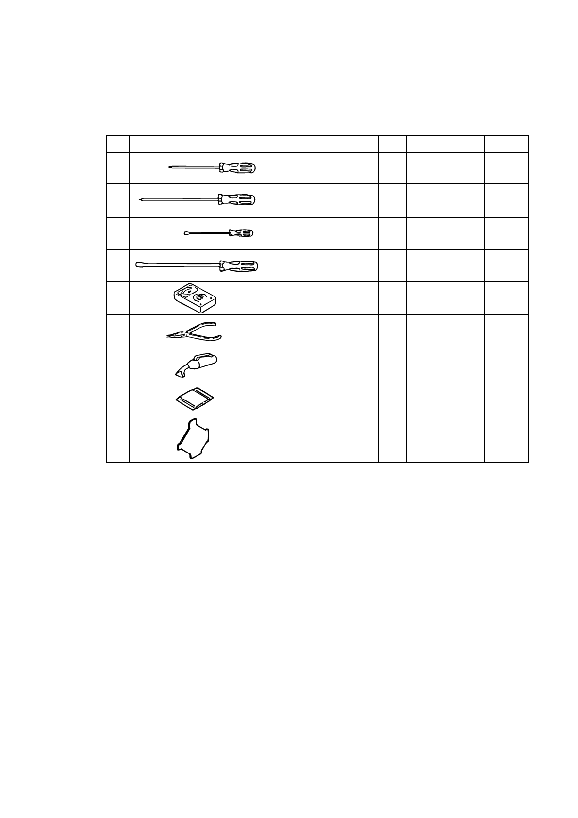
Table 3-1 shows tools necessary to replace the parts.
Table 3-1 Tools for Maintenance
No. Q' ty Use for RemarkService Tools
3. Parts Replacement
1
2
3
4
5
6
7
8
9
Driver No.1-100
Driver No.2-200
Driver No.3-300
+
+
+
Driver No. 5-200
Digital multimeter
Pliers
Handy Cleaner
LED Head cleaner
Drawing No: 4PB4083-2248P1
Jack-in Connector Pulling
Tools
Drawing No: 4PP4076-5395P1
1
2~2.5 mm screws
1
3~5 mm screws
1
1
1
1
1
1
LED Head Cleaning
1
Jac-in Connector
Pulling
40801701TH Rev.2 29 /
Page 30
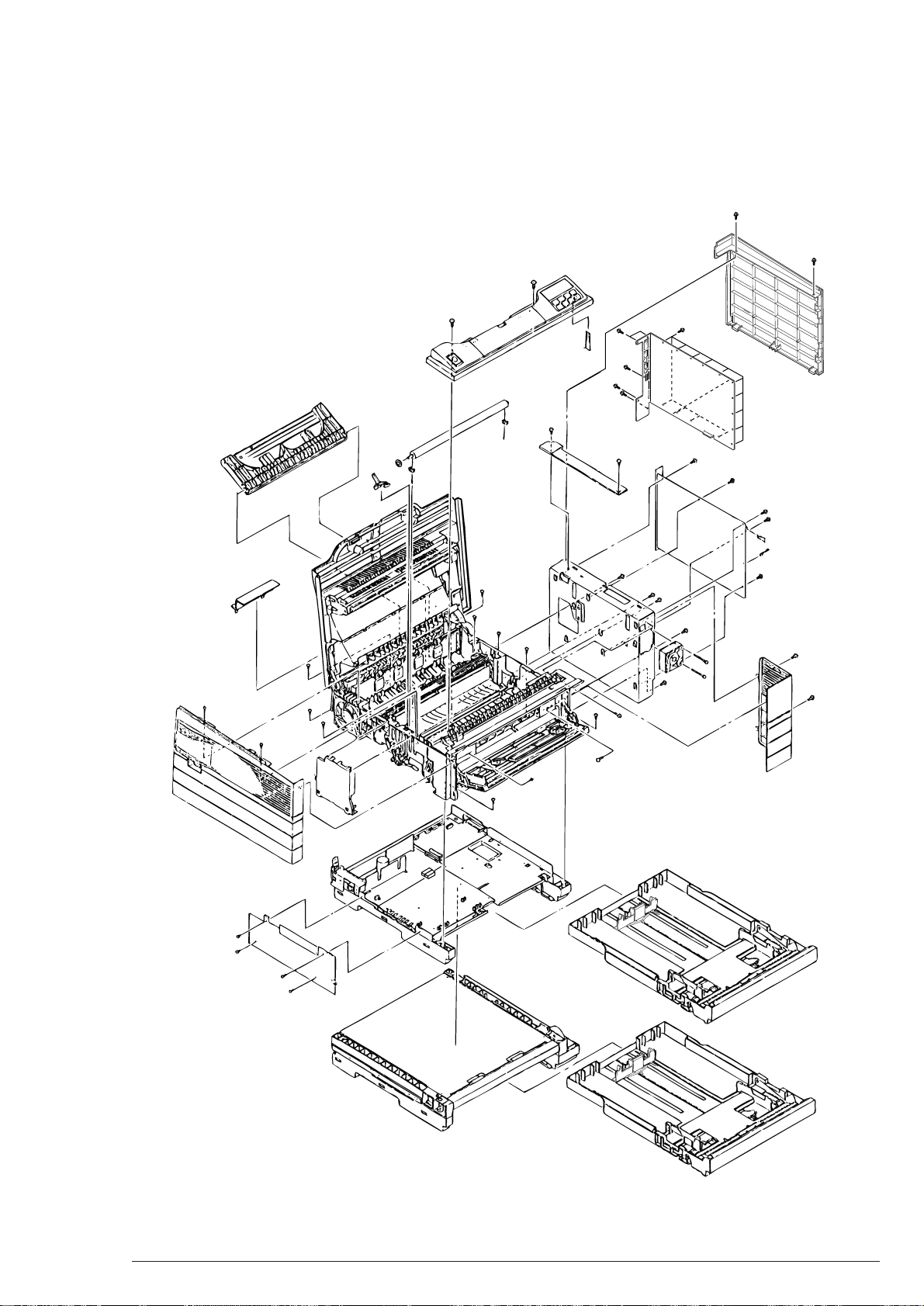
3.2 Parts layout
This section describes the layout of the main parts.
3. Parts Replacement
Figure 3-1
40801701TH Rev.2 30 /
Page 31

[Main Chassis Unit]
3. Parts Replacement
Figure 3-2
40801701TH Rev.2 31 /
Page 32

[Front Feeder Assy]
3. Parts Replacement
Figure 3-3
40801701TH Rev.2 32 /
Page 33

[Base Unit]
3. Parts Replacement
Figure 3-4
40801701TH Rev.2 33 /
Page 34

[Second Tray Unit]
3. Parts Replacement
Figure 3-5
40801701TH Rev.2 34 /
Page 35

3. Parts Replacement
Printer Unit Face-up Stacker Assy
(3.3.1)
Contact Assy
(3.3.2)
DC Fan Motot
(3.3.3)
Stacker Cover Assy,
DC12V Fan Motor,
Damper Arm
(3.3.6)
Fuser Assy
(3.3.14)
Damper
(3.3.7)
Eject Roller Assy
(3.3.8)
Fusing Guide
(3.3.15)
Back-up Roller
(3.3.16)
Operater Panel
Assy
(3.3.4)
SRA-PCB
(3.3.5)
Separation
Piece (Sticky)
(3.3.9)
FF Roller,
Bearing F
(3.3.10)
Paper Feed Motor
(3.3.11)
LED Head
(3.3.21)
Paper Cassette
(3.3.22)
Transfer Roller, TR Gear, TR Beaing
(3.3.23)
Resister Roller
Assy
(3.3.12)
Motor Assy
(3.3.13)
Hopping Roller Assy
(3.3.17)
Power
Supply
(3.3.18)
Paper End
Lever
(3.3.19)
Detector
Spring,
LLSW-PCB
(First Tray)
(3.3.20)
Feeding
Roller
(3.3.24)
Detector
Spring,
LLSW-PCB
(Second Tray)
(3.3.25)
3.3 Parts Replacing Methods
This section describes the methods for replacing the parts and assemblies shown in the following disassembing
system diagram.
40801701TH Rev.2 35 /
Page 36

3. Parts Replacement
3.3.1 Face-up Stacker Assy
(1) Turn off the AC power switch and pull the AC power cord out of the outlet.
(2) Disconnect the interface cable 1.
(3) After opening the face-up stacker Assy 2 and removing the right and left protrusions, detach the
face-up stacker Assy 2.
2
1
40801701TH Rev.2 36 /
Page 37

3. Parts Replacement
3.3.2 Contact Assy
(1) Open the stacker cover 1 and the manual feed hopper Assy 2, remove the three screws 3, and
detach the side cover (L) Assy 4.
(2) After removing the four screws 5, detach the plate (contact) 6 and the contact Assy 7.
Note:
4
Take care not to deform the electrode plate of the contact Assy 7.
3
1
3
5
7
2
5
6
40801701TH Rev.2 37 /
Page 38

3. Parts Replacement
3.3.3 DC Fan Motor
(1) Detach the side cover (L) Assy. [See 3.3.2 (1).]
(2) The connector of the DC fan motor 1 must be detached before demounting the DC fan motor 1.
1
40801701TH Rev.2 38 /
Page 39

3. Parts Replacement
3.3.4 Operator Panel Assy
(1) Disconnect the interface cable 1.
(2) Open the stacker cover 2 and remove the two screws 3 to detach the I/F cover 4.
(3) By removing the two screws 5 and the corner card 6, the operator panel Assy 7 is released.
5
7
1
6
3
4
2
40801701TH Rev.2 39 /
Page 40

3. Parts Replacement
8
9
3
3
7
A
B
C
C
5
3
0
D
4
3
2
6
1
1
3.3.5 SRA-PCB
(1) Demount the operator panel Assy. (See 3.3.4.)
(2) Remove the nineteen screws C and detach the Shield plate D.
(3) Remove the three screws 9 and detach the connector panel 8.
(4) Remove the screw 7, then demount the hard disk unit 6.
(5) Remove the three screws A to detach the Ethernet board B.
(6) Remove the three screws 1 to detach the side cover R 2.
(7) After releasing the SRA-PCB 5 from the six screws 3 and the two connectors 4, detach it with
moving backward.
40801701TH Rev.2 40 /
Page 41

3. Parts Replacement
3.3.6 Stacker Cover Assy, DC12V Fan Motor, Damper Arm
(1) Detach the face-up stacker. (See 3.3.1.)
(2) Remove the side cover (L) Assy. [See 3.3.2 (1)]
(3) Demount the operator panel Assy. (See 3.3.4)
(4) Detach the SRA-PCB. (See 3.3.5)
(5) By removing the two screws 1, detach the cover 2.
(The cable of the LED head and the cable guide are also released then.)
(6) Remove the two clicks and detach the connector cover 3 to disconnect the LED head cable.
(7) Remove the two screws 6 to detach the DC12V fan motor 7.
(OP905 ; Remove the two screws C to detach the LED Cooling fan.)
(8) Remove the six screws 4 to detach the side plate R 5.
(9) Detach the back-up release lever 8 and disconnect the protrusion on the right surface of the gear on
the right of the stacker cover.
(10) Remove the screw 9 and the washer 0 to detach the stacker cover Assy A.
(At the same time, the damper arm B is released.)
40801701TH Rev.2 41 /
Page 42

A
9
3. Parts Replacement
C
Only OP905
D
1
2
3
Protrusion
0
4
4
4
B
8
7
6
4
5
4
40801701TH Rev.2 42 /
Page 43

3.3.7 Damper
(1) Detach the damper arm. (See 3.3.6.)
(2) Remove the two screws 1, then detach the two dampers 2.
2
3. Parts Replacement
1
40801701TH Rev.2 43 /
Page 44

3.3.8 Eject Roller Assy
(1) Detach the stacker cover Assy. (See 3.3.6.)
(2) After unlatching the right side of the eject roller 1, raise it to release.
1
3. Parts Replacement
40801701TH Rev.2 44 /
Page 45

3. Parts Replacement
3.3.9 Separation Piece (Sticky)
(1) Open the manual feed hopper Assy 1 and undo the fits in its lower part both on the right and the left.
(2) Set the manual feed hopper Assy 1 vertical, then detach the right and left levers.
(3) Demount the operator panel Assy. (See 3.3.4.)
(4) Remove the four screws 2 to detach the front feeder Assy 3.
(5) Detach the inner cover 6 after removing the four screws 4.
(At the same time, the cover lock lever 6 and the torsion spring 7 are released.)
(6) Remove the two screws 8 to detach the square connector 9.
(7) The switch code Assy 0 must be removed from the square connector 9 by using the exclusive tools.
(8) Revolve the idle gear A in the arrow A direction to raise the FF plate (sticky) B.
(9) Detach the front gear C, then remove the two springs D.
(10) Release the paper feeding guide F from the four screws E.
(The FF earth plate G is also released then.)
(11) Undo the two points of connection to detach the FF plate (sticky) B.
(12) Raise the separation piece (sticky) H to your side, then unlatch the two parts.
(Also the two springs I are released. Be careful not to lose them.)
40801701TH Rev.2 45 /
Page 46

2
3. Parts Replacement
1
2
3
40801701TH Rev.2 46 /
Page 47

6
7
4
4
9
8
C
A
0
D
I
F
B
D
G
H
E
E
E
E
5
A
3. Parts Replacement
40801701TH Rev.2 47 /
Page 48

3. Parts Replacement
3.3.10 FF Roller Assy, Bearing F
(1) Deatch the manual feed hopper Assy. [See 3.3.9 (1) and (2).]
(2) Detach the front feeder Assy. [See 3.3.9 (3) and (4).]
(3) Remove the paper feeding guide A. [See 3.3.9 (5) to (10).]
(4) Detach the idle gear 1 and then detach the FF cam on the R side, the release lever (R) 3 and the
spring 4.
(At the same time, the knock pin 5 and the bearing (F) 6 are released. Take care not to lose them.)
(5) Pull out the FF shaft 7 to the left to detach the FF roller boss 8.
(Give attention to the direction of the one-way clutch of the FF roller boss 8.)
(6) Release the FF cam 0, the release lever (L) A and the spring B from the nock pin 9.
The bearing (F) on the L side is also released then.
(7) Remove the FF roller D from the FF roller boss 8.
Note:
When assembling the FF roller to the FF roller boss, pay attention to its direction.
Also apply ethylalcohol to the inside of the FF roller boss and attach it to the FF roller boss in one
movement. Remove strain of the roller rubber by revolving the FF roller on the boss four to five
times immediately after assembling. If the applied alcohol is insufficient and the rubber does not
revolve on the boss lightly, try again. Be careful to protect the one-way clutch from alcohol.
4
1
2
3
6
5
7
9
B
C
D
8
A
0
40801701TH Rev.2 48 /
Page 49

3. Parts Replacement
3.3.11 Paper Feed Motor
(1) Detach the manual feed hopper Assy. [See 3.3.9 (1) and (2).]
(2) Demount the operater panel Assy. (See 3.3.4.)
(3) Detach the front feeder Assy. [See 3.3.9 (4).]
(4) Detacn the inner cover and the square connector. [See 3.3.9 (5) and (6).]
(5) The connector of the paper feed motor 1 must be detached from the square connector, using the
exclusive tools.
(6) Remove the paper guide A. [See 3.3.9 (6) to (10).]
(7) Detach the release lever (R). [See 3.3.10 (4).]
(8) After removing the two screws 2, detach the side plate R Assy 3.
(9) Remove the four screws 4, then detach the paper feed motor 1.
4
1
3
2
40801701TH Rev.2 49 /
Page 50

3.3.12 Resister Roller Assy
(1) Detach the front feeder Assy. [See 3.3.9 (1) to (4).]
(2) Remove the four screws 1, then raise to detach the resister roller Assy 2.
3. Parts Replacement
Note:
While the screws 1 are removed, the stacker cover must be close.
1
2
1
40801701TH Rev.2 50 /
Page 51

3. Parts Replacement
3.3.13 Main Motor, Resister Motor
(1) Detach the resister roller Assy. (See 3.3.12.)
(2) Detach the stacker cover Assy. (See 3.3.6.)
(3) Detach the front feeder Assy. [See 3.3.9 (1) to (2).]
(Detaching the manual feed hopper Assy is not required then.)
(4) Demount the second unit.
(5) Detach the earth plate (HP) 1.
(6) The TR gear 2 and the TR roller 3 are released by pressing the TR release lever and unlocking.
(ML803PSII has no TR release lever.)
(7) Remove the connector cover 5 to detach the four connectors.
(8) Removing the nine screws 6 detaches the main chassis 7.
(9) Unlatch the back-up release lever 8 and pull out on the right.
(At the same time, the idle gear is released.)
(10) Detach the springs 0, then detach the pressure release lever A.
(11) Remove the EP lock spring B and detach the EP lock lever C.
(12) By unlatching the two parts, detach the motor Assy D.
Note:
The detached TR roller is to be wrapped in paper. Do not put it directly on the floor.
40801701TH Rev.2 51 /
Page 52

5
6
2
3
6
3. Parts Replacement
8
9
A
C
6
0
B
1
4
6
7
Second Unit
6
D
40801701TH Rev.2 52 /
Page 53

3. Parts Replacement
3.3.14 Fuser Assy
(1) Detach the side cover (L) Assy. [See 3.3.2 (1).]
(2) Pull out the connector 1.
(3) Remove the four screws 3 and detach the fuser Assy 2 with holding the top of it by hands.
Note:
• The temperature of the fuser Assy 2 is high directly after the power is turned off. Work after
it cools well.
• After replacing the parts, reset the counter. (See Section 4.2.)
3
2
3
40801701TH Rev.2 53 /
Page 54

3. Parts Replacement
3.3.15 Fusing guide
(1) Detach the fuser Assy. (See 3.3.14.)
(2) Removing the two screws 1 and the three points of clicks releases the fuser guide Assy 2.
1
2
1
40801701TH Rev.2 54 /
Page 55

3.3.16 Back-up Roller
(1) Detach the fuser Assy. (See 3.3.14.)
(2) Detach the back-up release lever. [See 3.3.13 (8).]
(3) Detach the fuser guide. (See 3.3.15.)
(4) Disconnect the back-up roller 2 from the earth plate L 1 (BK) and raise it.
(At the same time, the two back-up roller bearings 3 and the two bias springs 4 are released.)
3. Parts Replacement
3
4
3
4
2
1
40801701TH Rev.2 55 /
Page 56

3. Parts Replacement
3.3.17 Hopping Roller Assy
(1) Detach the main chassis. [See 3.3.13 (1) to (8).]
(2) Unlatch and detach the hopping roller gear 1 and the bearing R 2, then detach the idle gear HF 3.
(3) Unfix the left side of the hopping roller shaft from the groove and pull out the hopping roller shaft 4
and the hopping roller Assy 5 to the left.
(4) Unlatch the bearing L 6 to detach it.
(5) Unlatch and detach the hopping roller Assy 5.
(The knock pin is also released then. Be careful not to lose it.)
7
4
3
1
2
6
40801701TH Rev.2 56 /
5
Page 57

3. Parts Replacement
3.3.18 Power Supply
(1) Unfix the main chassis. [See 3.3.13 (1) to (8).]
(2) Remove the two screws 1 to detach the inlet holder 2.
(Remove the inlet 3 from the inlet holder 2 then.)
(3) Detach the seven screws 4, the three connectors 5, the three screws 6 and three Nylon latch 0,
then detach the mechanism control board 8 together with the power supply 7.
(4) Disconnect 9 the power supply 7 from the board.
Note:
Be careful not to deform the paper end lever.
4
4
3
4
7
2
6
5
4
9
4
6
8
6
1
1
0
Paper End Lever
40801701TH Rev.2 57 /
Page 58

3.3.19 Paper End Lever
(1) Unfix the main chassis. (See 3.3.15.)
(2) Detach the power supply. (See 3.3.18.)
(3) Unlock and detach the paper end lever 1.
3. Parts Replacement
1
40801701TH Rev.2 58 /
Page 59

3.3.20 Detector Spring, LLSW-PCB (First Tray)
(1) Unfix the main chassis. [See 3.3.13 (1) to (7).]
(2) Remove the insulator 1.
(3) After removing the two screws 2, detach the base plate 3.
(4) Unscrew 4 the detecter spring 5 to detach it.
(5) Remove the screw 6 and detach the LLSW-PCB 7.
3. Parts Replacement
1
2
3
2
7
6
5
4
40801701TH Rev.2 59 /
Page 60

3. Parts Replacement
3.3.21 LED Head
(1) Open the stacker cover 1.
(2) Detach the PC connector 2 from the LED head 4.
(3) Pushing over the hook on the left of the stacker cover 1 in the arrow direction unfixes the LED head
4.
(4) Pull the head spring 5 out of the post.
4
2
2
OP905
4
2
1
3
5
5
40801701TH Rev.2 60 /
Page 61

3.3.22 Paper Cassette
1
(1) Pull the paper cassette Assy 1 out of the printer.
3. Parts Replacement
40801701TH Rev.2 61 /
Page 62

3.3.23 Transfer Roller, TR Gear, TR Bearing
3
2
4
1
6
4
5
5
Green
Green
(1) Open the stacker cover 1.
(2) Pressing the TR release lever 6 releases the TR gear 2 and the transfer roller 3.
3. Parts Replacement
Note:
(3) Unfix the two right and left TR bearings 4 from the main chassis, sliding the bearings to the inside
The detached transfer roller 3 shall not be put directly on the desk. Lay paper to put it.
with pressing it. The two transfer springs 5 are also released then.
40801701TH Rev.2 62 /
Page 63

3.3.24 Feeding Roller
(1) Demount the second unit 1. [See 3.3.13 (1) to (4).]
(2) Remove the four screws 1 and unfix the upper plate 2.
(3) Detach the front roller Assy 3.
(4) Removing three screws 4 releases the cassette guide (R) Assy 5.
(5) Unlatch the feeding gear 6 and the feeding bearing 7, then detach the feeding roller.
(The bearing 9 is also released. Take care not to lose it.)
1
2
3. Parts Replacement
1
1
8
3
4
4
4
6
9
4
7
5
40801701TH Rev.2 63 /
Page 64

3.3.25 Detector Spring, LLSW-PCB (Second Tray)
(1) Demount the second unit [See 3.3.13 (1) to (4).]
(2) Detach the cassette guide (R) Assy. [See 3.3.24 (1) to (4).]
(3) The detecter spring 1 is released by unscrewing 2.
(4) Remove the screw 3 and unfix the LLSW-PCB 4.
4
3. Parts Replacement
3
1
2
40801701TH Rev.2 64 /
Page 65

4. Adjustment
y
Model Name
OP904
OP905
Head Specification
600DPI
A3
1200DPI
A3
Nameplate
This section describes the necessary adjustments after replacing the parts.
The following shows units replaced and necessary adjustments on them.
Part Replaced Adjustment
4. Adjustment
LED Head
Fuser
Drum Cartridge
4.1 LED Head Driving Time Set-up
Note:
When a set-up indication on a replacement LED head (new one) is the same as that of an used
LED head (old one), setting its LED head driving time is not required.
Set-up Indication Label
LED Head Driving Time Set-up (See Section 4.1)
Fuser Counter Reset (See Section 4.2)
Drum Counter Reset (See User's Manual)
(OP905)
(OP904)
Set-up Indication
(expressed b
40801701TH Rev.2 65 /
Last Three Digits)
Page 66

4. Adjustment
4.1.1 Outline of Set-up Procedure
The following shows the outline of the LED head driving time set-up procedure. See “4.1.2 Driving Time Setup” for details after No. 3.
1. Take off the rear cover and the connector cover.
2. Switch the POWER on to “I”, pressing the switch (SW1) of the mechanism control board (Engine
controller) by the switch bar. (to obtain the printer maintenance mode.)
3. Set LED head driving time according to the set-up indication on the LED head.
4. Switch the POWER off to “O”.
5. Switch the POWER on to “I” again and proceed with the usual printing operation.
LED
Switch(SW1)
Rear Cover
HIR-PCB , LLEH-PCB
Connector Cover
ROM
40801701TH Rev.2 66 /
Page 67

4. Adjustment
4.1.2 Driving Time Set-up
To arrange LED head driving time, set a driving time set-up address corresponding to the set-up indication on
the LED head in EEPROM, using the switch on LLEH PCB (OP904) or HIR PCB (OP905).
a. Set-up Indication - Driving Time Corresponding Table
OP904 600dpi
LED Head Set-up
Indication
011
012
013
014 ~ 015
016
017
018 ~ 019
020
021 ~ 022
023 ~ 024
025 ~ 026
027 ~ 028
029 ~ 031
032 ~ 034
035 ~ 036
037 ~ 039
Drive Time Set-up
Address
16
15
14
13
12
11
10
9
8
7
6
5
4
3
2
1
LED Head Set-up
Indication
040 ~ 043
044 ~ 046
047 ~ 050
051 ~ 054
055 ~ 059
060 ~ 063
064 ~ 068
069 ~ 073
074 ~ 080
081 ~ 087
088 ~ 096
097 ~ 101
102 ~ 113
114 ~ 120
121 ~ 128
129 ~ 138
Drive Time Set-up
Address
0
31
30
29
28
27
26
25
24
23
22
21
20
19
18
17
b. Set-up Indication - Driving Time Corresponding Table
OP905 1200dpi
LED Head Set-up
Indication
046 ~ 048
049 ~ 051
052 ~ 054
055 ~ 057
058 ~ 061
062 ~ 065
066 ~ 069
070 ~ 074
075 ~ 079
080 ~ 084
Drive Time Set-up
Address
16
15
14
13
12
11
10
9
8
7
6
5
4
3
2
1
LED Head Set-up
Indication
085 ~ 088
089 ~ 094
095 ~ 010
101 ~ 107
108 ~113
114 ~ 121
122 ~ 129
130 ~ 137
138 ~ 145
146 ~ 155
156 ~ 166
167 ~ 175
Drive Time Set-up
Address
0
31
30
29
28
27
26
25
24
23
22
21
20
19
18
17
40801701TH Rev.2 67 /
Page 68

Example: In the case of the address “0” > “14”
The LED head driving time is specified in the parameter No. 13.
Operation LED Indication Followed Remark
4. Adjustment
Switch the POWER on to "I", pressing the switch (SW1).
Press the switch (SW1) short twelve
time.
Press the switch (SW1) long one
time. (Set Address is indicated.)
Press the switch (SW1) short fourteen times.
Press the switch (SW1) long one
time.
The lamp lights short one time.
The lamp lights short thirteen times.
Thirteen times Thirteen times
The lamp lights long one time and
short ten times.
Ten times Ten times
The lamp lights long one time, short
one time, and shot four times.
The lamp lights short thirteen times.
Thirteen times Thirteen times
Printer Maintenance Mode
Selecting Parameter No.13
(Example)
Indicates Address "0".
Indicates Address "14".
Setting in EEPROM
(Indicating Parameter
No.13)
Switch the POWER off to "O".
Short Press
Long Press
: One pressing time is one sec. or less., ,
: One pressing time is one sec. or more.,
b. Adjustment after Set-up
The set address may be adjusted to the next above or before address only.
: LED Lighting Form
: Short Lighting, : Long Lighting
40801701TH Rev.2 68 /
Page 69

4.2 Fuser Counter Reset (only OP905)
After replacing the fuser, reset the fuser counter by using the following procedure.
1. Set the printer to the printer maintenance mode. (See 1 to 3 of Section 4.4.1.)
2. Reset the fuser counter.
For the fuser counter, the value is specified in the parameter No. 3.
Operation LED Indication Followed Remark
4. Adjustment
Switch the POWER on to "I", pressing the switch (SW1).
Press the switch (SW1) short twice.
Press the switch (SW1) long one time.
(Set Counter Value is indicated.)
Press the switch (SW1) long one time.
Press the switch (SW1) short one
time.
Switch the POWER off to "O".
The lamp lights short one time.
The lamp lights short three times.
The lamp lights eight cycles over, at one
long and one short lightings per cycle.
The lamp lights ten cycles over, at one
long and one short lightings per cycle.
Ten times Ten times
The lamp lights short three times.
Printer Maintenance Mode
Selecting Parameter No.3
(Example)
Indicates 14111 pages.
Resetting Value of Counter.
(Indicating Parameter
No.3)
Short Press
Long Press
3. Switch the POWER on to “I” again and proceed with the usual printing operation.
: One pressing time is one sec. or less., ,
: One pressing time is one sec. or more.,
: LED Lighting Form
: Short Lighting, : Long Lighting
40801701TH Rev.2 69 /
Page 70

5. Routine Maintenance
White Stripe, White Belt
(Void or Light Printing)
5. Routine Maintenance
5.1 Routine Replacement Parts
Routine replacement parts and units must be replaced according to the following standard.
Table 6-1 Routine Replacement Parts
Replacement Parts
Toner Cartridge
Drum Cartridge
Note:
Even when “DRUM LIFE” is displayed, the drum cartridge can be used until the toner is used
up.
Replacement Time
When "TONER LOW" is displayed.
When "DRUM LIFE" is displayed.
Check Point
LED Head
Remark
Consumable
Consumable
5.2 Cleaning
• Remove toner/foreign matters and clean with waste around and inside the printer.
• In case of frequent paper jams (PAPER FEED JAM or EJECTION JAM), see Section 3.3.14.
Detach the fuser Assy and clean the back-up roller surface with waste to clean adhering toner and paper
dust.
(Cleaning with alcohol is recommended against much dirt.)
Note:
Do not touch the OPC drum.
5.2.1 LED Lens Array Clearning
When a white stripe or a white belt (void or light printing) appears vertically on the printed surface, clean the
LED lens array or replace the toner cartridge.
Note:
Use LED head cleaners when cleaning the LED Lens array.
40801701TH Rev.2 70 /
Page 71

5. Routine Maintenance
(1) Set the LED head cleaner to the LED lens array as shown in the following figure. Clean it, moving the
cleaner horizontally several times.
Note:
Do not press the LED head cleaner towards the LED lens array.
LED Head Cleaner
LED Lens Arry
40801701TH Rev.2 71 /
Page 72

6. Troubleshooting Produre
6. Troubleshooting Produre
6.1 Prior to Repairing
(1) Be sure the basic points to be checked described in Users Manual.
(2) Obtain information from the customers concerning the situation in which the trouble occurred in details
as much as possible.
(3) Checking the printer in condition close to the trouble is required.
6.2 Check Points prior to Handling Imperfect Image
(1) Machine Operating Circumstances Proper.
(2) Consumables (toner, drum cartridge) Replaced Appropriately.
(3) Paper Normal
(4) Drum Cartridge Set Properly
6.3 Precautions on Handling Imperfect Image
(1) Do not touch the OPC drum surface with hands and foreign matters.
(2) Keeping the OPC Drum out of direct sunlight is essential.
(3) The fuser becomes very hot. Do not touch it with hands.
(4) The image drum shall not be kept in light for 5 minutes or more at room temperature.
40801701TH Rev.2 72 /
Page 73

6.4 Preparation for Troubleshooting
ON-LINESERVICE
OPERATOR
MANUAL
MENU MENU SELECT
MANUAL START
RESET TRAY SELECT ON-LINE
Trouble
Occurred
Trouble Appeared on
LCD in Message
Form
Locate a fault by using LCD
Status Messate List
See Section 6.5.1.
Locate a fault, using detailed
Troubleshooting Flowchart.
See Section 6.5.1.
Imperfect Image
Trouble (or Trouble
Not Appeared on
LCD Message)
Locate a fault, using detailed
Troubleshooting Flowchart.
See Section 6.5.1 and Section
6.5.4.
(1) Operator Panel Display
Failure statuses of the machine are appeared on the LCD (Liquid Crystal Display) of the operator
panel.
Troubleshoot according to each message on the LCD appropriately.
6. Troubleshooting Produre
6.5 Troubleshooting Methods
If any trouble occurs out of the printer, locate a fault by using the following procedure.
6.5.1 LCD Status Message List
Table 6-1 lists status and troubles to be appeared on the LCD in message form.
40801701TH Rev.2 73 /
Page 74

Table 6.1(1/3) LCD Status Message List
•
•
•
•
•
•
•
•
•
•
•
•
•
•
Cover Open
Engine Block
Error
COVER OPEN
ERROR PU
ROM/RAM CHECK
ERROR PU
EEPROM ERROR
ERROR PU
EEPROM WRITE
ERROR PU
CONTROL
ERROR PU-OPTION
I/F TIMEOUT
ERROR PU
S-RAM ERROR
ERROR PU
FAN MOTOR
ERROR PU
FUSER UNIT
Stacker Cover Opened
Engine ROM or RAM Check
Error Occurred
No Engine EEPROM, or EEPROM Damaged
Engine EEPROM Write Error
Occurred
Engine Firmware Got Out of
Control.
PU Second Tray Communication Error Occurred
Engine S-RAM Check Error
Occurred
DC Fan Stopped, No Power
(+38V) Supplied to DC Fan
Fuser Temperature Not
Reached, or Over Specified
Temperature
• Thermistor Shortcircuit or
Disconnection
Close Stacker Cover.
In case the same message is
displayed even after closing
Stacker Cover, replace Mechanism Control Board or PU Power
Unit.
Replace Mechanism Control
Board.
Check whether EEPROOM is
built.
Replace EEPROM.
Replace Mechanism Control
Board.
- Same as the above -
Replace Mchanism Control
Board.
Check whether Second Tray is
attached properly.
Replace Second Tray or
Mechanism Control Board.
Replace Mchanism Control
Board.
Check whether there is a foreign matter in DC Fan.
Check whether DC Fan Connector is connected.
Replace DC Fan or Mechanism Control Board.
See 6.5.2 4.
Classification Message on LCD Fault Remedy
6. Troubleshooting Produre
40801701TH Rev.2 74 /
Page 75

Table 6.1(2/3) LCD Status Message List
•
•
•
•
•
•
•
Jam Error PAPER INPUT JAM
PAPER FEED JAM
PAPER EXIT JAM
REMOVE THE PAPER
ERROR PAPER SIZE
Jam Occurred in Cassette
Leading Part of Paper does
not reach inlet Sensor after
Hopping Roller works. (Retried three times)
Or Inlet Sensor is on when
power is turned on.
Jam Occurred in Paper Feeder
If Specified Time elapses after starting Resister Roller,
Leading Part of Paper does
not reach Write Sensor.
If Specified Time elapses after starting Resister Roller,
Leading Part of Paper does
not reach Outlet Sensor.
Write Sensor does not turn off
within a certain time after Paper End passed Inlet Sensor.
Write Sensor is on before Inlet Sensor turns on.
Write Sensor is off before Inlet Sensor turns off.
Inlet or Write Sensor is on
when power is turned on.
Jam Occurred in Outlet Sensor
Running Time of Paper on
Outlet Sensor does not meet
Specifiedified one, or Outlet
Sensor is on when power is
turned on.
Error Occurred in case Length
of Printing Paper is different
from that Printer recongnized (or
Tray size), or Length of Paper
used is different from that set by
Cassette or Menu.
Detection based on Running
Time of Paper on Inlet Sensor
and by Inlet Sensor.
Open Cover to remove Jammed
Paper, and close Cover.
See 6.5.2 2-1.
Open Cover to remove Jammed
Paper, and close Cover.
See 6.5.2 2-2.
Open Cover to remove Jammed
Paper, and close Cover.
See 6.5.2 2-3.
See 6.5.2 3.
Classification Message on LCD Fault Remedy
•
•
•
•
•
•
•
•
•
6. Troubleshooting Produre
40801701TH Rev.2 75 /
Page 76

Table 6.1(3/3) LCD Status Message List
Controller Error
CU-PU
Communication
Error
CU EEPROM ERROR
ERROR SERIAL
COMMUNICATION
HDD ERROR
ERROR CU-PU
I/F TIMEOUT
ERROR CU-OPTION
I/F TIMEOUT
ERROR CU-PANEL
I/F TIMEOUT
SRA EEPROM Check Error
(Unable to write)
Protocol Error Occured om Serial I/F (such as Parity Error,
Framing Error) or Receiving
Data from Deselect Serial I/F
Ports Detected.
Built-in Hard Disk Error Occurred With Unformatted Hard
Disk.
I/F Error Occurred between CU
and PU.
I/F Error Occurred between CU
and Tray 2 Paper Feed Unit.
I/F Error Occurred between CU
and Operator Panel.
Press "RESET" switch to restore
the system to the condition in
which the machine is shipped. If
this does not recover the system,
replace SRA PCB Board.
Set the contents of Menu to the
higher devices.
See 6.5.2 7.
Press "RESET" switch to restore
Disk File to the initial condition. If
the system does not resume, see
6.5.2 6.
Classification Message on LCD Fault Remedy
•
6. Troubleshooting Produre
40801701TH Rev.2 76 /
Page 77

6. Troubleshooting Produre
6.5.2 LCD Message Troubleshooting
If the printer can not be repaired after the fault locating by the LCD Status Message List, troubleshoot based on
the following Troubleshooting Flowchart.
Item Fault Flowchart No.
1. Printer does not operate properly after power is turned on. 1
2. Jam Alarm
Paper Load Jam 2-1
Paper Feed Jam 2-1
Paper Ejection Jam
3. Paper Size Error 3
4. Fusing Error 4
5. Fan Error 5
6. HDD Error 6
7. Serial I/F Error 7
40801701TH Rev.2 77 /
Page 78

1 The printer does not operate properly when power is turned on.
Turn off the power, then turn on again.
"INITIALIZING" is displayed?
NO AC input is normal?
NO Check the AC connection.
↓
YES +38V is being output?
NO Fuse in Power Supply Unit is broken?
↓
YES Check whether the circuit between +38V-0V is shorted before
replacing Fuse.
NO Power is output when AC is tuned on after detaching Mechanism Control
Board? (at Power Supply Unit)
↓
YES Check whether the circuits between +38V-0V and +5V-0V are
shorted. (on Mechanism Control Board)
6. Troubleshooting Produre
NO Replace Power Supply Unit.
YES “ “ is displayed on Operator Panel 16 seconds after power is turned on?
↓
YES Replace Control Board.
NO Connection Cord of Operator Panel is released?
↓
YES Connect Connection Cord.
NO Replace Operator Panel.
YES Alarm Indicator Lamp lights?
↓
YES Troubleshoot according to each indication.
NO Fan rotates?
↓
NO Replace Mechanism Control Board.
YES Replace Control Board.
40801701TH Rev.2 78 /
Page 79

[Jam Alarm]
2-1 Hopping JAM (PAPER INPUT JAM)
Jam Alarm lights when paper is loaded?
YES Paper is fed to the underside of Inlet Sensor Lever?
YES Inlet Sensor Signals on?
NO Replace Mechanism Control Board.
NO Replace Hopping Roller or Paper Feed Assy.
NO Hopping Roller is turning?
YES Set Tray properly.
6. Troubleshooting Produre
[Check by Tenth Pin on Mechanism Control Board 02F (74HC158).]
YES Check the Inlet Sensor Lever operation.
NO Replace Paper Feed Assy or Mechanism Control Board.
• In the case of Second Tray, replace Paper Feed Assy or Mechanism Control Board LLFL
PCB.
• Check Pulse Motor (Resister). If any trouble with Pulse Motor, replace it.
40801701TH Rev.2 79 /
Page 80

[Jam Alarm]
2-2 Paper Feeding Jam (PAPER FEED JAM)
Paper Feeding Jam occurs when power is turned on?
YES Paper exists on Paper Sensor or Inlet Sensor 1 to 3?
YES Remove Paper.
NO Signals of Paper Sensor or Inlet Sensors 1 to 3 turn on/off?
(Check Mechanism Control Board or Power Supply Unit.)
YES Check the Lever operation of Write Sensor or Inlet Sensor 1 to 3.
NO Check Mechanism Control Board or Power Supply Board.
NO Paper Feed Jam takes place when paper is loaded?
NO End
6. Troubleshooting Produre
YES Leading Part of Paper stops at Resister Roller?
YES Resister Roller is rotating?
NO Replace Mechanism Control Board.
YES Check Paper Feeder.
YES Paper reaches Outlet Sensor?
NO Pulse Motor (Main) rotates?
NO Replace Mechanism Control Board or Pulse Motor (Main).
YES Fuser is rotating?
NO Check Gears.
YES Check Paper Feeder.
YES Outlet Sensor turns on/off?
(Check it on Power Supply Board.)
NO Replace Power Supply Board.
YES Check the Outlet Sensor Lever operation.
40801701TH Rev.2 80 /
Page 81

[Jam Alarm]
2-3 Paper Exit Jam (PAPER EXIT JAM)
Paper Exit Jam occurs when power is turned on?
YES Paper is on Outlet Sensor?
YES Remove Paper.
NO Outlet Sensor Signals turn on/off?
(Check it on Power Supply Board.)
YES Check the Sensor Lever operation.
NO Replace Power Supply Board.
NO Paper Ejection Jam takes place when paper is loaded?
NO End
6. Troubleshooting Produre
YES Heat Roller is turning smoothly?
NO Check Gears.
YES Outlet Sensor Signals turn on/off?
(Check it on Power Supply Board.)
NO Replace Power Supply Board.
YES Outlet Sensor Lever operates normally?
NO Replace Outlet Sensor Lever.
YES Check Paper Feeder.
40801701TH Rev.2 81 /
Page 82

6. Troubleshooting Produre
Paper Feeding Direction
Figure 6-1
Eject Roller
Outlet Sensor
Heat Roller
Transfer Roller
Paper Sensor
Resist Roller
Inlet Sensor 1
Hopping Roller
Toner
Sensor
Inlet
Sensor 2
Inlet
Sensor 3
Paper End
Sensor
3 Different Paper Size (ERROR PAPER SIZE)
Leading Part of Paper stops at Resister Roller?
YES The length and width of paper caused the error are different from those of Tray?
YES Use regular-size paper.
NO Inlet Sensors 2 and 3 turn on/off?
(Check it on Power Supply Board)
YES Check the Lever operations of Inlet Sensors 2 and 3.
NO Replace Power Supply Board.
NO The size of paper caused the error is different from that of Tray by ±45 mm?
YES Use regular-size paper.
NO Paper Cassette is set properly?
NO Adjust Paper Cassette properly.
YES Paper slips when loading?
YES Check Paper Feeder.
NO Paper Cassette is correctly recognized?
(Recall Paper Size Command from the host to compare them.)
↓
YES End
NO Replace Mechanism Control Board LLSW PCB or Power Supply Board.
40801701TH Rev.2 82 /
Page 83

4 Fuser Unit Error “ERROR PU FUSER UNIT”
Heater Contact
Thermistor Contact
Figure 6-2
6. Troubleshooting Produre
Note:
Reset Fuser Counter after replacing Fuser. (See Section 4.2.)
• Turn off power and turn on again.
• Fuser Error occurs just after power is turned on?
YES • Thermistor Disconnection or Short
Circuit occurs?
• Measure Resistance between
Thermistor Contacts. (approx. 220k
Ω at room temperature)
YES Replace Fuser Assy.
NO Thermistor Contacts properly connect to Contact Assy in mounting Fuser Assy?
NO Correct the contact.
YES Replace Mechanism Control Board or Power Supply/Sensor Board.
NO Fuser Error takes place about 60 seconds after power is turned on?
NO Check whether the contact with or in Thermistor is faulty. Or, replace Mechanism
Control Board.
YES Turn off power, then turn on again.
Fuser Assy Heater turns on? (Check whether the lamp lights.)
YES Replace Fuser Assy or Mechanism Control Board.
NO Heater or Thermostat disconnection occurs? (approx. 0Ω)
YES Replace Fuser Assy.
NO AC is supplied to Heater use Contact of Contact Assy?
NO Replace Mechanism Control Board or Power Supply/Sensor Board.
YES Check whether the contact with or in Heater Contact Assy of Fuser Assy is poor.
5 Fan Error
Fan is rotating?
YES Replace Mechanism Control Board.
NO Connector CN5 on Power Supply Board is connected?
NO Connect Connector CN5.
YES Replace Fan or Mechanism Control Board.
40801701TH Rev.2 83 /
Page 84

6 HDD Error
HDD Unit is connected firmly?
NO Re-connect it.
Initializing HDD recovers it?
YES End
NO Replacing HDD recovers it.?
(Initialize HDD by using Maintenance Menu after replacement.)
YES End
NO Replace SRA PCB.
7 Serial I/F Error (SERIAL I/F ERROR)
Menu Contents are set to Higher Device or Personal Computer?
6. Troubleshooting Produre
NO Set Menu to the higher devices.
NO -12V is being supplied to SRA PCB Serial I/F Driver?
NO Check the power supply wiring system.
YES Replace SRA PCB.
40801701TH Rev.2 84 /
Page 85

6.5.3 Imperfect Image Troubleshooting
If any imperfect image is printed, troubleshoot the system as follows:
Figure 6-3 shows imperfect image output examples.
Problem Flowchart number
6. Troubleshooting Produre
Printing Light or Blurred, Whole (Figure 6-3 A )
White Background Dirty (Figure 6-3 B )
Blank Paper Output (Figure 6-3 C )
Vertical Black Belts or Stripes Appeared (Figure 6-3 D )
Periodic Imperfect Image Appeared (Figure 6-3 E )
Printing Missed
Poor fusing (When touched with hands, the image runs or comes off.)
Vertical White Belts or Stripe Appeared (Figure 6-3 F )
1
2
3
4
5
6
7
8
A Light or Blurred
Printing, Whole
D Vertical Black Belt/
Stripe
B White Background
Dirtiness
E Periodic Imperfect Image F Vertical White Belt/
Figure 6-3 Imperfect Image
C Blank paper
Stripe
40801701TH Rev.2 85 /
Page 86

6. Troubleshooting Produre
1 Printing Light or Blurred, Whole
Toner is short? ("TONER LOW" is displayed?)
YES Supply toner.
NO Designated paper is used?
NO Use designated paper.
YES LED Head Lens is dirty?
YES Clean LED Head.
NO LED Head is properly attached? (Check Mechanism Control Board Head 1 and Head 2
Connectors.)
NO Attach LED Head properly.
YES Transfer Roller Contact Plate and Power Supply/Sensor Board properly touch?
(See Figure 6-5.)
NO Touch them together properly.
YES Drum Cartridge Terminals properly contact Contact Assy? (See Figure 6-4 A , B .)
NO Contact them properly.
YES Replace Transfer Roller.
Recovered?
YES End
NO Replace Drum Cartridge.
Recovered?
YES End
Note:
The drum counter must be reset after replacing the drum cartridge.
(See “Image Drum Cartridge Replacement” in Section 6 “User Printer
Maintenance” of Users Manual.)
NO Replace Power Supply/Sensor Board.
40801701TH Rev.2 86 /
Page 87

6. Troubleshooting Produre
2 White Background Dirty
OPC Drum was left in outer light?
YES Set it in the device, and wait for 30 minutes.
NO Fuser Unit Heat Roller is dirty?
YES Clean Heat Roller.
NO Drum Cartridge Terminal properly touches Contact Assy ? (See Figure 6-4, C .)
NO Contact it properly.
YES Replace Drum Cartridge.
Recovered?
YES End
Note:
Reset the drum counter after replacing the drum cartridge.
(See “Image Drum Cartridge Replacement” in Section 6 “User Printer
Maintenance” of Users Manual.)
NO Replace Power Supply/Sensor Board.
3 Blank Paper Output
LED Head is connected properly? (Check Mechanical Control Board Head 1 and Head 2 Connectors.)
NO Connect LED Head properly.
YES Drum Cartridge Terminal is contacted properly? (See Figure 6-4, D .)
NO Check the ground contact point of Drum Cartridge.
YES Replace LED Head.
Recovered?
YES End
Note:
Set LED head driving time when replacing the LED head.
(See 4.2.1.)
NO Replace Mechanism Control Board, and Control Board or Supply/Sensor Board.
40801701TH Rev.2 87 /
Page 88

4 Vertical Black Belt or Stripe Appeared
• Replace Drum Cartridge.
• Recovered?
YES End
6. Troubleshooting Produre
Note:
Reset the counter after replacing the drum cartridge.
(See “Image Drum Cartridge Replacement” in Section 6 “User Printer
Maintenance” of Users Manual.)
NO Replace LED Head.
Recovered?
YES End
Note:
Set LED head driving time when replacing the LED head.
(See 4.2.1.)
NO Replace Mechanism Control Board or Power Supply/Sensor Board.
5 Periodic Imperfect Image Appeared
Interval Remedy
94.2mm
Replace Drum Cartridge.
Note:
52.1mm
33.8mm
88.6mm
Replace Drum Cartridge.
Replace Drum Cartridge.
Replace Fuser Assy.
Reset the Drum counter after replacing the drum cartridge. (See “Image Drum Cartridge
Replacement” in Section 6 “User Printer Maintenance” of Users Manual.)
40801701TH Rev.2 88 /
Page 89

6 Printing Missed
Transfer Roller Contact Plate and Power Supply/Sensor Board properly touch?
NO Touch them together properly.
YES Replace Transfer Roller.
Recovered?
YES End
NO Drum Cartridge Terminals properly touch Contact Assy?
(See Figure 6-4 A to E .)
NO Contact them to Contact Assy properly.
YES Replace Drum Cartridge.
Recovered?
6. Troubleshooting Produre
YES End
Note:
Reset the drum counter after replacing the drum cartridge.
(See “Image Drum Cartridge Replacement” in Section 6 “Printer User
Maintenance” of Users Manual.
NO LED Head is properly mounted? (Check Mechanism Control Board Head 1 and Head 2
Connectors.)
NO Attach LED Head properly.
YES Replace LED Head.
Recovered?
YES End
Note:
Set LED head driving time, when replacing the LED head.
(See 4.2.1.)
NO Replace Mechanism Control Board or Power Supply/Sensor Board.
40801701TH Rev.2 89 /
Page 90

6. Troubleshooting Produre
7 Poor Fusing
The designated paper is used?
NO Use the designated paper.
YES Bias Spring (Back-up) is normal?
NO Replace Bias Spring (Back-up).
YES Fuser Assy Heat Roller properly contacts Contact Assy? (See Fugure 6-4.)
NO Touch them together properly.
YES Replace Fuser Assy.
Recovered?
YES End
NO Replace Mechanism Control Board or Power Supply/Sensor Board.
40801701TH Rev.2 90 /
Page 91

6. Troubleshooting Produre
8 Vertical White Belt or Stripe Appeared
LED Head Lens is dirty?
YES Clean LED Head Lens.
NO Transfer Roller Contact Plate properly touches Power Supply/Sensor Board? (See Figure 6-5.)
NO Contact it properly.
YES Replace Transfer Roller.
Recovered?
YES End
NO LED HEAD is properly attached? (Check Mechanism Control Board Head 1 and Head 2
Connectors)
NO Attach LED Head properly.
YES Replace LED Head.
Recovered?
YES End
Note:
Set LED Head driving time when replacing LED Head. (See 4.2.1.)
YES Replace Drum Cartridge.
Recovered?
YES End
Note:
Reset the drum counter after replacing Drum Cartridge.
(See “Image Drum Cartridge Replacement” in Section 6 “User Printer
Maintenance” of Users Manual.)
NO Replace Mechanism Control Board or Power Supply/Sensor Board.
Note:
Reset Drum Counter after replacing Drum Cartridge.
(See “Image Drum Cartridge Replacement” in Section 6 “User Printer
Maintenance” of Users Manual.)
NO Replace Mechanism Control Board or Power Supply/Sensor Board.
40801701TH Rev.2 91 /
Page 92

6. Troubleshooting Produre
F
E
D
C
A
B
Figure 6-4
40801701TH Rev.2 92 /
Page 93

6. Troubleshooting Produre
Contact Plate
Figure 6-5
40801701TH Rev.2 93 /
Page 94

6. Troubleshooting Produre
6.5.4 Manual Feed Hopper Assy Opening/Closing Troubleshooting
(1) If the manual feed hopper cannot be opened for any reason, open it in the following way:
(2) If the manual feed hopper cannot be closed for any reason, use the following procedure:
Manual Feed Hopper Assy
Strongly
in the diredtion of the arrow.
pull the manual feed hopper Assy tab
1. Place the printer off-line.
2. Load one sheet of paper in the front feeder.
3. Carry out local test printing.
If you are unable to open or close the manual feed hopper after trying the above, replace the front feeder Assy
and the manual feed hopper.
40801701TH Rev.2 94 /
Page 95

ENVE
Envelope Unit
Paper End
Sensor
MT
Tray 2
Front ENVE
LLSW
Second
Tray
SW4 SW2
SW1SW3
HOME SW
LLFL-2
Front Paper End
Tray 1
Main
Motor
Register
Motor
MotorResister
15
1
SW1
SW1
D1
LED Head Module
Head 1(OP905x2) Head 2(OP905x2)
EP ROM
LLEH/HIR
Engine Control
SRA Controller
1
16
1
LLJB
Operator
Panel
ACIN
AC Switch
POW1
CN1
CN6 CN7
Power Supply Unit
[AC-DC(230V)]
Power Supply Unit
(High Voltage)
1
114
1112
112
14
32
12 3
6
40
PU
Heater
Thermistor
SW2
SW4
CNT
SW3
5
First Tray
Hopping
1
15
1
1
1
111
111
1
1
1
1 4 567 89
11
234 123
12
11
4
5
7
17
17
12 17
17
17
12
7.1 Connection Diagram
7. Connection Diagram
7. Connection Diagram
40801701TH Rev.2 95 /
Page 96

7. Connection Diagram
Fuser Assy
Between 1 and 2 pins : 220Ω (25˚C)
Between 3 and 4 pins : 8.5Ω (240V)
Pusle Motor (Drum)
Between 1 and 2 pins : 5.1Ω
Between 3 and 4 pins : 5.1Ω
Pulse Motor (Resister)
Between 1 and 2 pins : 6.7Ω
Between 3 and 4 pins : 6.7Ω
Orange
Heater
3 Thermostat
4
Thermistor
1
2
Yellow
M
1
2
Brown
Black
3
4
Red
Yellow
M
1
2
Blue
Orange
3
4
40801701TH Rev.2 96 /
Page 97

7. Connection Diagram
Fan Motor
Between 1 and 2 pins : 4.9Ω
Pulse Motor (Hopping)
Between 1 and 2 pins : 6.7Ω
Between 3 and 4 pins : 6.7Ω
Red
Yellow
1
3
Black
2
+38V
FANALM-N
0V
M
Orange
Yellow
M
1
2
Brown
Black
3
4
40801701TH Rev.2 97 /
Page 98

7. Connection Diagram
Fan Motor
Between 1 and 2 pins : 4.9Ω
Pulse Motor (Second)
Between 1 and 2 pins : 6.7Ω
Between 3 and 4 pins : 6.7Ω
Orange
Yellow
M
1
2
Brown
Black
3
4
Red
1
Black
2
+12V
0V
M
40801701TH Rev.2 98 /
Page 99

7.2 Board Layout
(1) Power Supply/Sensor Board
PS3
PS4
PS5
7. Connection Diagram
PS7
SW2
CN3
PS2
PS1
PS6
CN7CN6
CN5
CN2
F5
F1
F7
40801701TH Rev.2 99 /
Page 100

(2) SRA-PCB
7. Connection Diagram
1 5
1 2
FANPWR
72 38
72 38
71
71
2 6
OP
ODDSIMM
14
IDE2
EVENSIMM
37
37
36 2
36 2
35
35
1
1
EEPROM
HEAD FAN
12
139
42 80
41 79
240
IDE
20
FROM
26 50
125
NIC
PUIF
FU2
1
21 40
APTK
13
1
14 25
3125
47
6
8
18
36
1
19
CENT
RS232C
40801701TH Rev.2 100 /
 Loading...