

Page 1
English
OKI® MICROLINE® 8810/8810n
Setup Guide
English . . . . . . . . . . . . . . . . . . . . . . . . . . . . . . . . . . . . . . . . . . . . . . . . . . . . . . . . . . . . . . . . . . . . . . . .1
French [Français] . . . . . . . . . . . . . . . . . . . . . . . . . . . . . . . . . . . . . . . . . . . . . . . . . . . . . . . . . . . . . . 12
Spanish [Español]. . . . . . . . . . . . . . . . . . . . . . . . . . . . . . . . . . . . . . . . . . . . . . . . . . . . . . . . . . . . . . 23
Brazilian Portuguese [Português] . . . . . . . . . . . . . . . . . . . . . . . . . . . . . . . . . . . . . . . . . . . . . . . . . 34
Space Requirements
Installation Summary
Unpack . . . . . . . . . . . . . . . . . . . . . . . . .1
Set Up the Printer . . . . . . . . . . . . . . . .2
Run a Self Test . . . . . . . . . . . . . . . . . . .7
Load Paper . . . . . . . . . . . . . . . . . . . . . .7
Connect to the Computer . . . . . . . . . .10
Step 1:
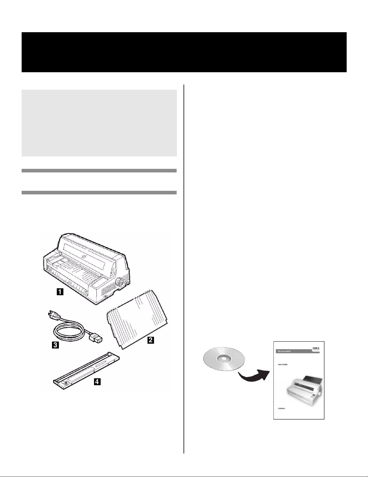
Unpack
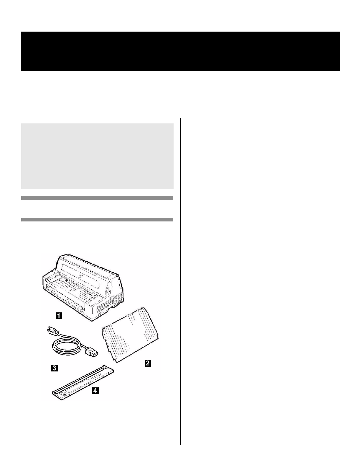
Check the Contents
If any items are missing, contact your dealer
immediately.
Place the printer on a stable, level surface.
Check that sufficient space is available for the
installation:
• Width: 35.4" (90 cm)
•Depth
– Behind printer: 23.6" (60 cm)
– In front of printer: 12.6" (32 cm)
– Overall: 60.2" (153 cm)
• Height: 18" (46 cm) minimum
Environmental Requirements
• Operating Temperature: 41 to 104°F (5 to 40°C)
• Humidity: 30 to 85% RH
Documentation
Your printer includes the following documentation:
•This
•
Setup Guide
How to get the printer up and running.
Safety and Regulatory Information
Important safety information, along with general
regulatory information (FCC, Energy Star, IC, etc.)
and the Material Safety Data Sheet for the ribbon.
booklet
1
Printer
2
Stacker
3
Power Cable
4
Ribbon Cartridge
Not illustrated: Documentation
Components Feb 17
06.jpg
Page 2
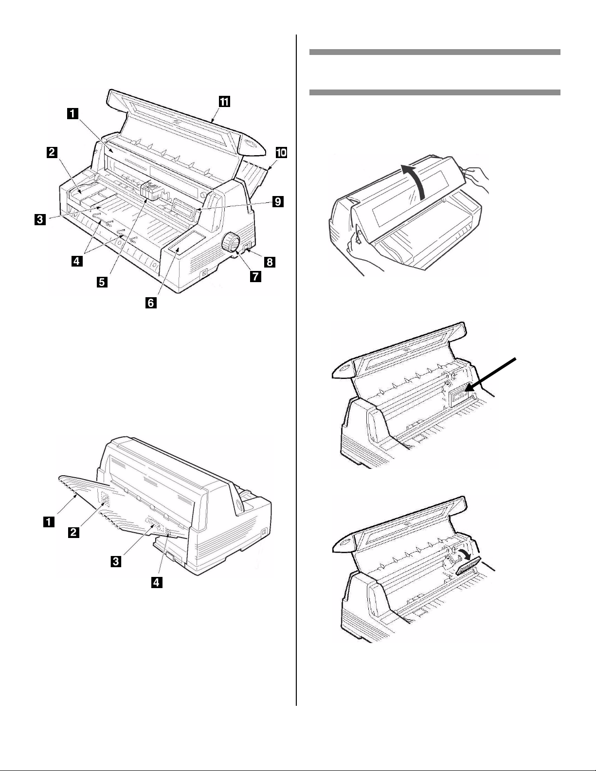
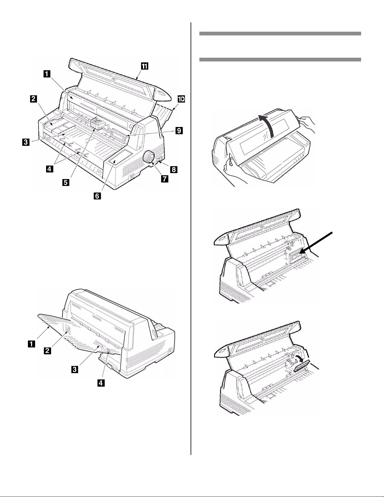
Printer Components
Front View
Step 2:
Set Up the Printer
Remove the Printhead Shipping
Restraint
1. Open the cover using the grips on either side.
F2_03_open_
cover.jpg
1
Ribbon Cartridge
2
Sheet Guide
3
Sheet Platform
4
Sheet Supports
5
Printhead
6
Control Panel
Rear View
7
Platen Knob
8
Power Switch
9
Display Panel
10
Stacker
11
Cover
F1_24a1.jpg
2. Peel the protective plastic film off the display
panel.
F2_15c.jpg
3. Tilt the display panel toward you.
F2_04_Tilt_D
isplay.jpg
1
Stacker
2
Power Socket
F1_24b1.jpg
3
Parallel Port
4
USB Port
2
Page 3
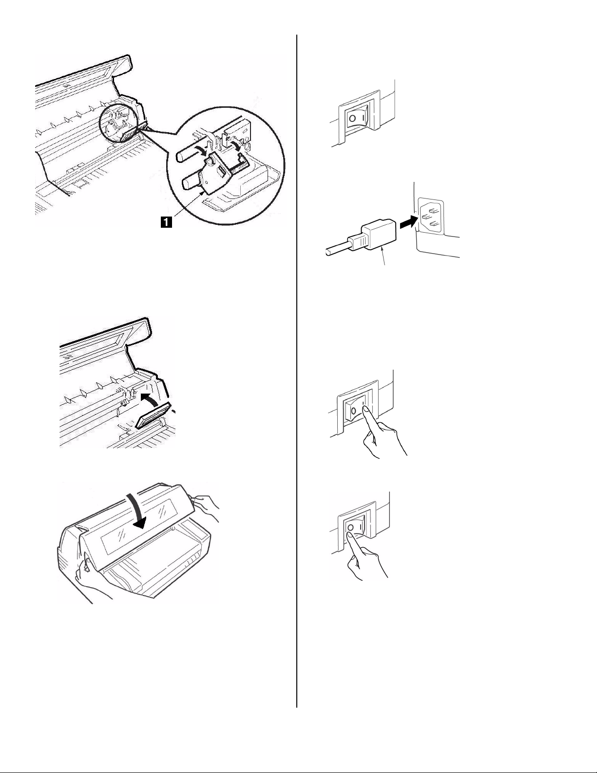
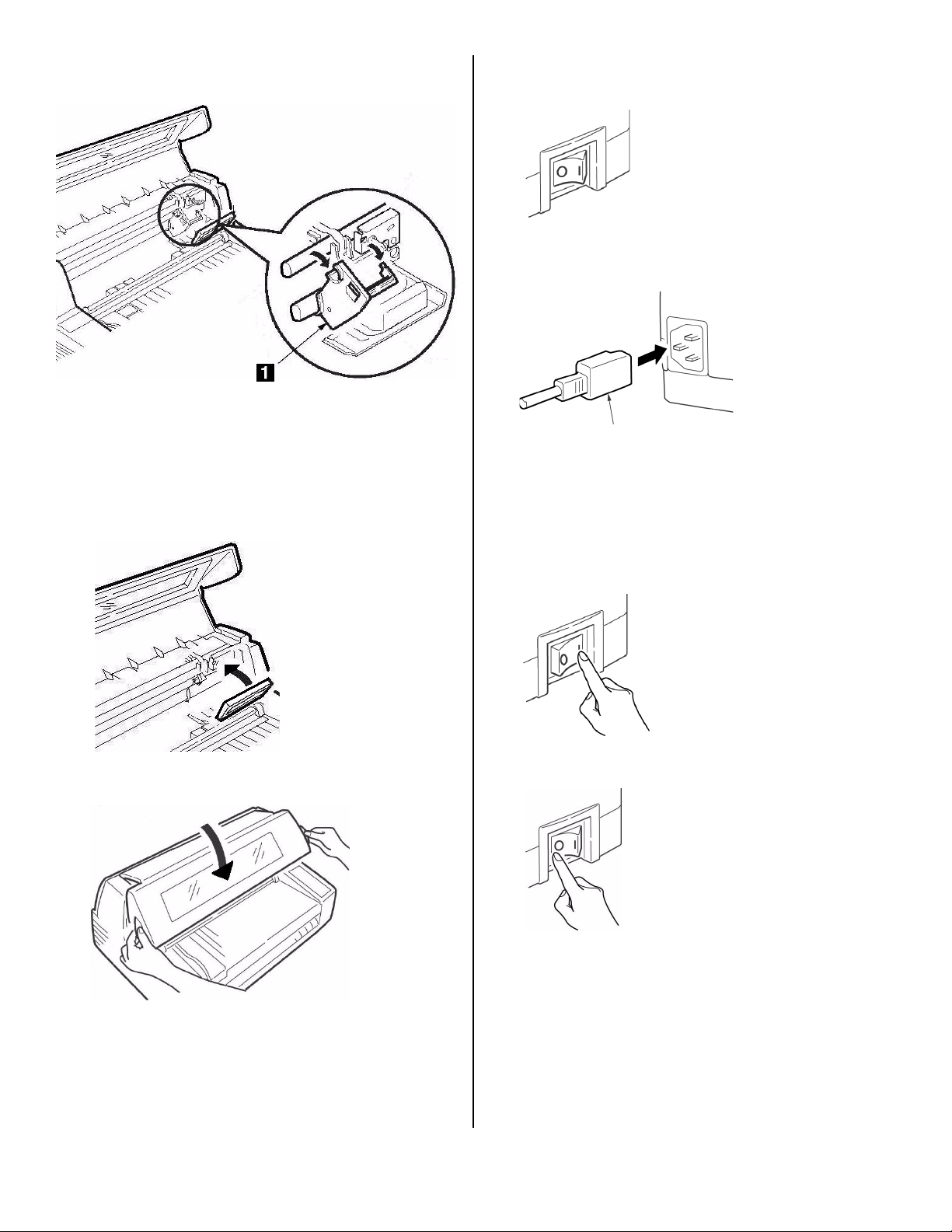
4. Remove the shipping restraint (1).
F2_04a.jpg
Note
Save the shipping restraint and packing materials
in case you ever need to ship the printer.
5. Push the display panel back to its original
position.
F2_04_Tilt_Display_
Back.jpg
Install the Power Cord
7. Make sure the printer power switch is in the OFF
position:
F2_06.jpg
8. Attach the power cord to the back of the printer.
F2_19.jpg
9. Plug the opposite end into a suitable, grounded
outlet.
Install the Ribbon Cartridge
1. Turn ON the printer.
The printhead lifts, moves to the left, then moves
to the center and stops.
6. Close the cover.
F2_03_close_c
over.jpg
2. Turn OFF the printer
F2_21.jpg
before
F2_06a.jpg
opening the cover.
3
Page 4
Warning!
Make sure the printer is turned off before you
open the cover.
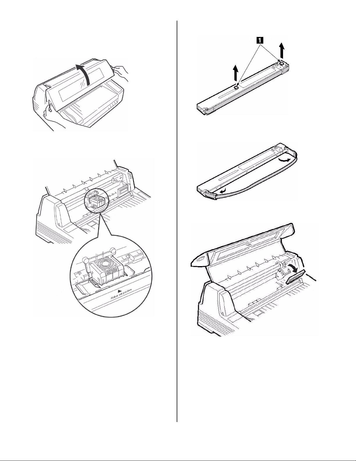
3. Open the cover.
F2_03_open_c
over.jpg
4. Verify that the printhead is centered (at the
“Ribbon set position”).
5. Unpack the ribbon cartridge and remove the lock
pieces (
1
).
F2_09.jpg
6. Swing out the ribbon arms on either end of the
cartridge until they
snap
into place.
F2_10a.jpg
F2_07a.jpg
7. Tilt the display panel toward you.
F2_04_Tilt_Display.J
PG
4
Page 5
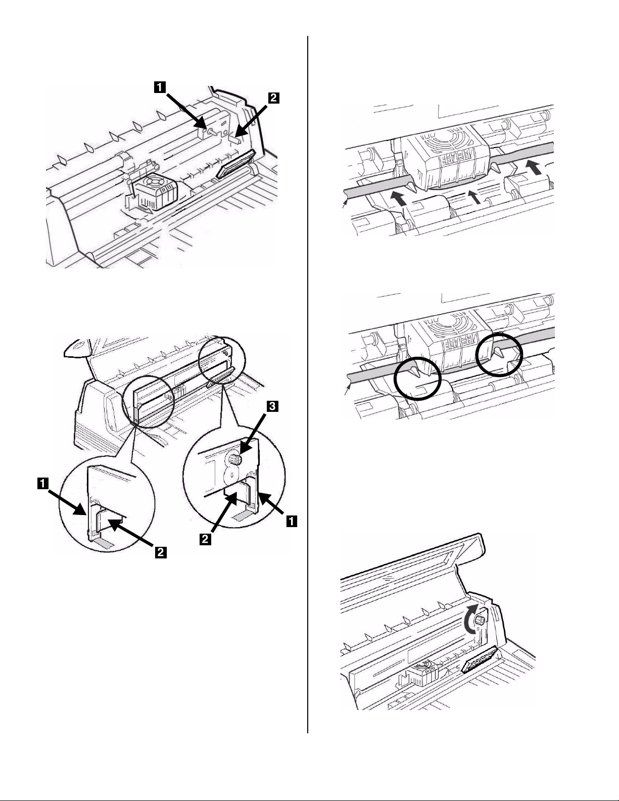
8. Observe the black pin (1) over which the ribbon
knob fits, and the guides (
2
)—one at either end—
into which the ribbon arms fit.
F2_07b.jpg
10. Pull the ribbon out a bit at the left end of the
cartridge to give some slack, then slide the ribbon
underneath the printhead. Be careful that the
ribbon is not twisted, folded or pulled off the
ribbon arms during this process.
F2_13a.jpg
11. Make sure the ribbon is threaded through the
indentation in each ribbon guide arm.
9. Feed the ribbon arms (
(
2
), position the take-up knob (3) over the pin,
1
) in beside the guides
then press the cartridge in firmly at either end.
F2_11a.jpg
Caution!
Always turn the ribbon knob
turning it
counter
clockwise (to the left) can
clockwise
cause the ribbon to jam.
12. Turn the ribbon knob
clockwise
(in the direction
of the molded arrow) to take up any excess slack
in the ribbon.
F2_1
3b.jp
g
:
F2_15a.j
pg
5
Page 6
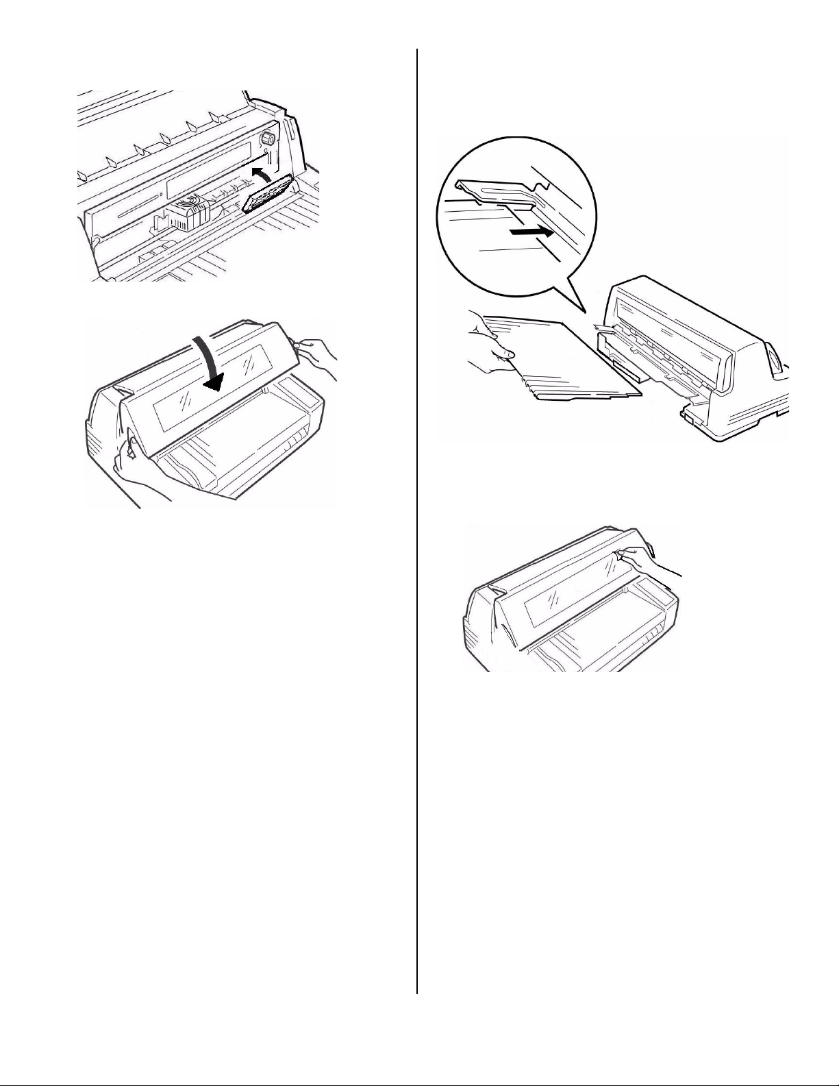
13. Push the display panel back to its original
position.
Install the Stacker
With the flat edge toward the printer and the frosted
side up, slide the stacker into the channels at either
end of the support, pushing it in as far as it will go.
F2_15b.jpg
13. Close the cover.
Caution!
If the cover does not close easily,
force it
. The right end of the ribbon
do not
cartridge is not properly seated in the
printer. Open the cover and reseat it. Then
reclose the cover.
F2_03_cl
ose_cove
r.jpg
F2_17_rev.jpg
Remove the Protective Film
Peel the protective plastic film off the viewing area on
the cover.
Remove_Prote
ctive_Plastic.jp
g
6
Page 7
Step 3:
Run a Self Test
Step 4:
Load Paper
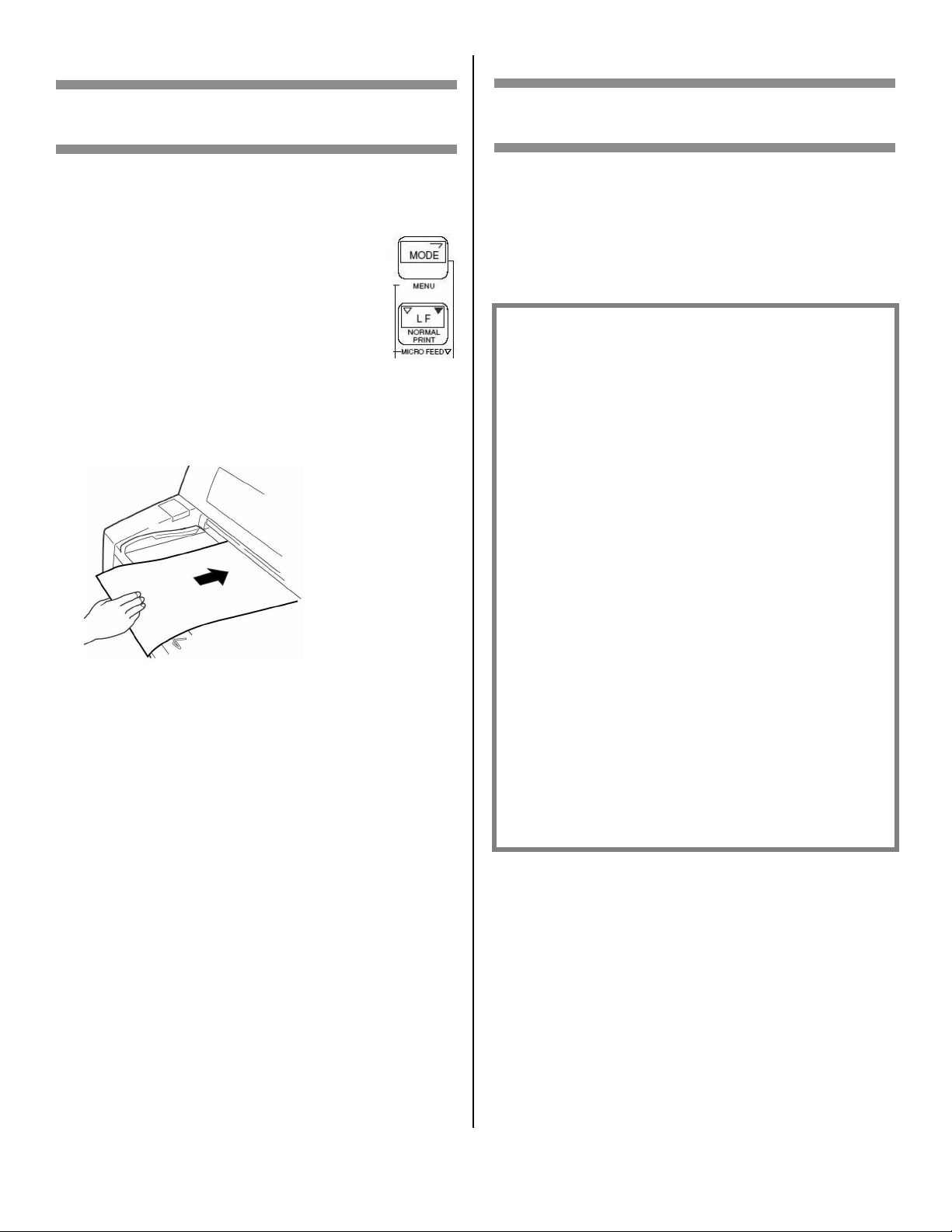
Before proceeding, run a self test to check that the
printer is operating correctly. This prints out a list of
available fonts.
1. Turn off the printer.
2. Press and hold MODE and LF while
turning on the printer. Release them
when
RELEASE SW
second line of the display.
3. When the printer finishes initializing,
the display will prompt you to insert
paper.
4. Place a letter size or larger sheet of paper on the
platform anywhere within the “Paper range when
Auto Align is ON” area.
appears on the
8810 MODE + LF.jpg
F5-11a.jpg
Individual Sheets/Forms (“MANUAL”)
The printer is set at the factory for
• single sheets/forms (Manual Feed)
• Auto Align mode
• automatic printhead gap (Auto Gap)
Paper Specifications,
for Use with Auto Align Mode
Minimum Print Margins
1/4-inch (6.4 mm) on all sides
Individual Sheets
•Size
– Minimum Width: 3.9” (100 mm)
– Maximum Width: 14.3” (364 mm)
– Minimum Length: 2.8” (70 mm)
– Maximum Length: 16.5” (420 mm)
•Weight
– Minimum:13.8 lb. US Bond (52 g/m2)
– Maximum: 55.8 lb. US Bond (210 g/m
2
)
The sheet feeds in. The test prints and the page is
ejected back out onto the platform.
The self test is complete.
Individual Multi-Part Forms
•Size
– Minimum Width: 3.9” (100 mm)
– Maximum Width: 14.3” (364 mm)
– Minimum Length: 2.75” (70 mm)
– Maximum Length: 16.5” (420 mm)
• Thickness
– Up to 8-part forms (original + 7)
– Maximum Thickness: 0.0189” (0.48 mm)
7
Page 8
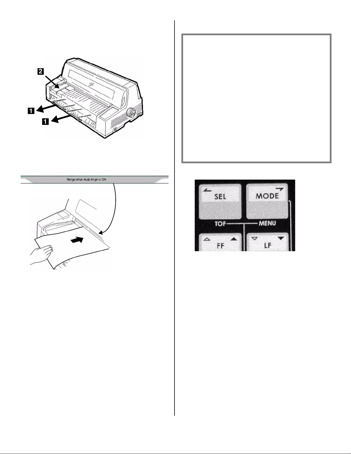
Load Individual Sheets/Forms
1. Pull out the sheet supports (1) and move the
sheet guide (
travel of the sheet guide is limited).
2. Place a letter size or larger sheet/form on the
platform anywhere within the “Paper range when
Auto Align is ON” area
2
) to the right as far as it will go (the
Sheet_G
uide_cro
p.jpg
Continuous Forms (“FRONT”)
Continuous Forms Specifications
•Width
– Minimum: 4” (102 mm)
– Maximum: 16” (406 mm)
• Single Thickness Forms
– Weight range: 14 to 34 lb. US Bond
(52.6 to 128 g/m2)
• Multi-part Forms: Front Feed Tractor
– up to 8-part forms (original + 7)
– Maximum Thickness: 0.0189” (0.48 mm)
• Multi-part Forms: Optional Rear Feed
Tractor
– up to 6-part forms (original + 5)
– Maximum Thickness: 0.0142” (0.36 mm)
Set the Printer for Continuous Forms
F5-11a.jpg
The sheet loads in to the print position,
automatically aligning so that it is square with the
print path.
8810_3_Crop.jpg
1. If there is a sheet loaded on the platform, remove
it.
2. With the printer turned on, press SEL to place the
printer off line.
3. Press MODE once or twice until you see
FRONT
on the second line of the display.
The printer changes paths and returns to the on
line state. FRONT appears on the second line of
the display.
Note
To switch back to single sheet feed, follow the
same steps, pressing MODE several times until
you see
MANUAL
on the second line of the
display.
8
Page 9
Load Continuous Forms
1. Push the sheet supports in and lift the sheet feed
platform
F5-03a.jpg
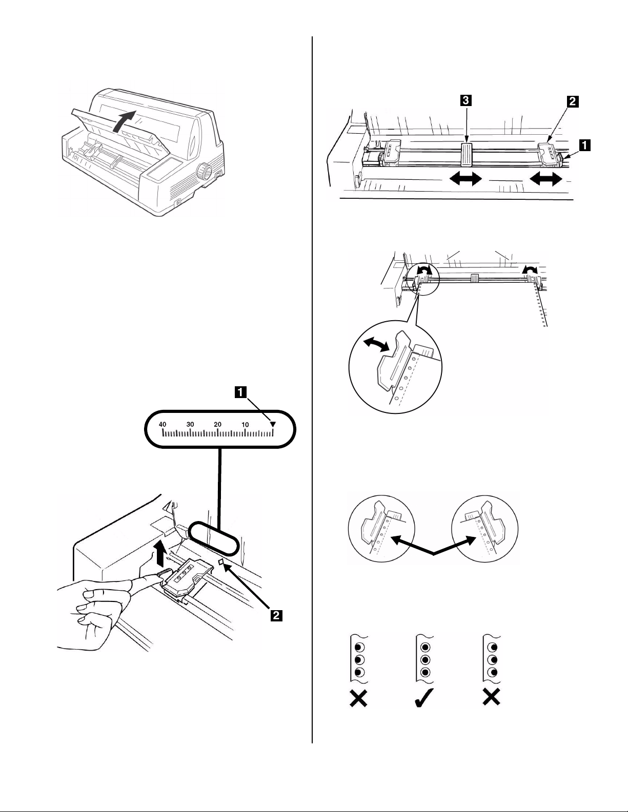
2. Lift the lock lever on the left tractor, then move
the left tractor to set the desired left margin for
printing.
•The
Note
The movement of the left tractor is limited to
ensure that the paper covers the paper out
sensor.
▼
mark on the gauge (1)—or the center of
the diamond shaped hole (
2
)—represents the
location of the center of the first character
printed.
1
4. Lift the lock lever (
) on the right tractor (2) and
move the tractor over to correspond to the width
of the continuous forms you are using. Center the
paper support (
F5-05a.jpg
3
) between the two tractors.
5. Open both tractor covers and place the first three
holes in the continuous forms paper over the pins.
F5-06a.jpg
8480_2_crop.jpg
F5-04a.jpg
3. Push the lock lever down to lock the left tractor in
place.
Important!
Make sure that an equal number of paper holes
are engaged on each tractor. If not, the paper
will jam.
F5-06b.jpg
6. Close the tractor covers and fine tune the position
of the right tractor until the holes in the paper are
centered on the pins, then push back the right
tractor lock lever.
F5-07a.jpg
7. Lower the platform.
9
Page 10
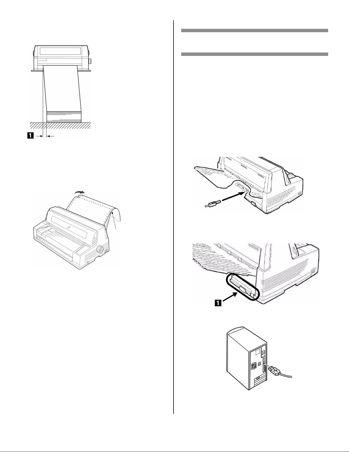
8. Position the continuous forms stack below the
printer with no more than about 1 inch (3 cm)
offset (
1
).
F5-08a.jpg
Tearing Off Printed Continuous Forms
9. With the SEL light on, press SHIFT.
The continuous forms move forward onto the
stacker.
10. Tear off the printed form along the perforation.
Step 5:
Connect to the Computer
Caution!
Do not connect both the USB and parallel
ports at the same time.
USB Port
Note
No USB interface cable is supplied with the
printer. Use a USB cable that is compatible with
USB specification 2.0.
1. Turn off the printer.
2. Connect the USB cable to the USB port on the
printer.
F3_02_c
rop.jpg
F5-09.jpg
11. Press SHIFT.
The forms move back into the printer, ready for
printing the next document.
Removing Continuous Forms
1. Follow the steps above to remove the printed
portion.
2. Press SEL.
3. Press LOAD.
The forms move back to the tractors.
4. Lift the platform and remove the forms from the
tractors.
5. Lower the platform.
3. Secure the cable in one of the channels (
1
)
molded into the housing on either side at the back
of the printer to keep it out of the way.
F1_24c.jpg
4. Connect the USB cable to the USB port on the
computer.
usb_pc.jpg
5. Turn on the printer.
10
Page 11
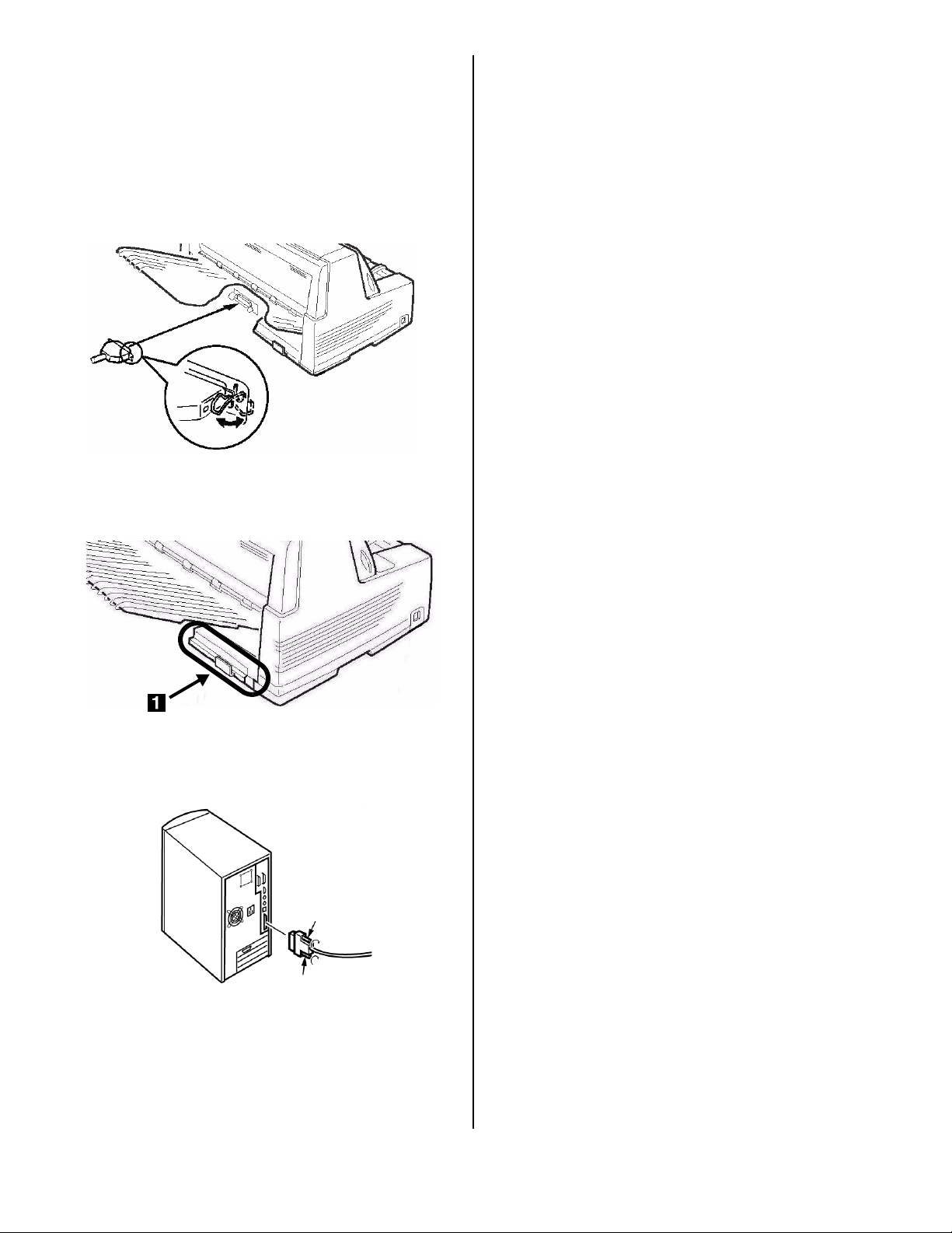
Parallel Port
Note
No parallel cable is supplied with the printer. Use
a shielded, bi-directional, IEEE-1284 compatible,
parallel cable no longer than 6 ft. (1.2 m).
1. Turn off the printer.
2. Connect the parallel cable to the parallel port on
the printer and secure it with the wire loops.
F3_03_crop.
jpg
The network print server is 10/100 Base-T Ethernet.
•Frames
– IEEE 802.3 and 802.3
– Ethernet-II
–SNAP
–Auto Detect
• Network Protocols
–TCP/IP
– IPX/SPX (NetWare)
–NetBEUI
• Functions
–Self-diagnostic
– Banner supported
– Configuration by Web browser
– Notification of printer status by Email
See the on-line User’s Guide on the CD supplied with
your printer for more information.
To Connect the Ethernet Port
3. Secure the cable in one of the channels (
1
)
molded into the housing on either side at the back
of the printer to keep it out of the way.
F1_24c.jpg
4. Connect the parallel cable to the parallel port on
the computer and secure it in place with the
screws.
parallel_pc.
jpg
1. Turn off the printer.
2. Connect one end of the Ethernet cable to the 10/
100B port on the back of the printer.
3. Connect the other end of the Ethernet cable to
the network.
5. Turn on the printer.
Network Port (Model 8810n Only)
Note
No Ethernet® cable is supplied with the printer.
Use an Ethernet cable with two twisted wire pairs
and an RJ45 plug.
11
Page 12
French [Français]
MICROLINE® 8810/8810n OKI
Guide d’installation
Sommaire de l'installation
Déballage . . . . . . . . . . . . . . . . . . . . . .12
Installez l'imprimante . . . . . . . . . . . .13
Effectuer un autodiagnostic. . . . . . . .18
Chargement du papier . . . . . . . . . . . .18
Connexion à l'ordinateur . . . . . . . . . .21
Étape 1:
Déballage
Vérifiez le contenu
Si des éléments sont manquants, avertissez
immédiatement votre revendeu.
®
Exigences espace
Placez l'imprimante sur une surface stable et solide.
Assurez-vous d'avoir assez d'espace pour
l'installation :
• Largeur : 90 cm (35,4")
•Profondeur
– derrière l’imprimante : 60 cm (23,6")
– avant l’imprimante : 32 cm (12,6")
– générales : 152,9 cm (60,2")
• Hauteur : 45,7 cm (18") minimum
Exigences environnementales
• Température de fonctionnement : 5 à 40°C (41 à
104°F)
• Humidité : 30 à 85% RH
Documentation
Votre imprimante est doté des documentation
suivantes :
•Ce
Guide d’installation
Pour installer et mettre rapidement votre imprimante
à l'oeuvre.
• Livret sur les
réglementation
Informations sur la sécurité importantes, ainsi que
Informations réglementaires générales (FCC, Energy
Star, IC, etc.) et la fiche technique santé-sécurité
pour le ruban.
•
Le Guide de l'utilisateur
situé sur le CD inclus avec l’imprimante.
Informations de sécurité et de
.
, un fichier PDF Acrobat
1
Imprimante
2
Empileuse
3
Cordon d’alimentation
4
Cartouche de ruban
Non illustrée : Documentation
Components Feb 17
06.jpg
Information sur les modes d’impression,
caractéristiques telles que le détachement de
formulaires et l’espacement automatique, le réglage
de haut de page, utilisation des réglages par défaut
de l'imprimante, dégagement des bourrages, etc.
12
Page 13
Composants de l'imprimante
Vue frontale
Étape 2:
Installez l'imprimante
Retirez l’élément d’emballage
protégeant la tête d’impression
1. Ouvrez le capot en saisissant les poignées de
chaque côté.
F2_03_open_
cover.jpg
1
Cartouche de ruban
2
Guide-papier
d'alimentation
3
Plate-forme feuille
4
Support de papier
5
Tête d'impression
6
Panneau de commande
Vue arrière
F1_24a1.jpg
7
Bouton d'Entraînement
8
Interrupteur
9
Panneau d'affichage
10
Empileuse
11
Couverture
2. Décollez le film plastique de l’affichage
F2_15c.jpg
3. Inclinez le panneau d’affichage vers vous.
F2_04_Tilt_
Display.jpg
1
Empileuse
2
Prise
3
Port parallèle
4
Port USB
F1_24b1.jpg
13
Page 14
4. Retirez l’élément d’emballage protégeant la tête
d’impression(
1
).
Installation du cordon d’alimentation
7. Assurez-vous que l'imprimante est hors tension :
F2_04a.jpg
Remarque
Conservez tous les éléments protecteurs et
d’emballage au cas où vous auriez besoin
d’expédier l’imprimante.
5. Repoussez le panneau d’affichage à sa position
d’origine.
F2_04_Tilt_Display_
Back.jpg
F2_06.jpg
8. Branchez le cordon d'alimentation à l'arrière de
l'imprimante.
F2_19.jpg
9. Pranchez l’autre extrémité du cordon à une prise
murale mise à la terre.
Installation du ruban
10. Allumez l'imprimante
La tête d’impression se soulève, se déplace vers
la gauche puis revient au centre et s’arrête.
6. Fermer le capot
F2_03_close_c
over.jpg
11. Éteignez l'imprimante
F2_21.jpg
avant
F2_06a.jpg
d'ouvrir le capot.
14
Page 15

Avertissement!
Nous prèconisons la mise hors circuit de
l’imprimante préalablement à enlévement du
capot de celle-ci.
12. Ouvrez le capot.
F2_03_open_c
over.jpg
13. Vérifiez si la tête d’impression est centrée (à la
position Ribbon Set [réglage du ruban]).
14. Déballez le ruban et retirez les verrous (
1
).
F2_09.jpg
15. Tirez les bras de chaque côté du ruban vers
l’extérieur jusqu’à ce qu’ils
s’enclenchent
place.
F2_10a.jpg
en
F2_07a.jpg
16. Inclinez le panneau d’affichage vers vous.
F2_04_Tilt_
Display.jpg
15
Page 16

17. Notez l’ergot noir (1) sur lequel se pose le bouton
de la cartouche de ruban, ainsi que les guides (
2
)
– un à chaque extrémité – sur lesquels se posent
les bras de la cartouche de ruban.
F2_07b.jpg
18. Passez les bras de la cartouche de ruban (
côté des guides (
bobinage de la cartouche (
2
) et placez le bouton de
3
) sur l’ergot, puis
1
) à
enfoncez fermement la cartouche à chaque
extrémité.
19. Tirez légèrement le ruban à l’extrémité gauche de
la cartouche pour obtenir un peu de jeu, puis
glissez le ruban sous la tête d'impression. Prenez
garde de ne pas tordre le ruban, le plier ou le
sortir des bras de la cartouche lors de
l'installation.
F2_13a.jpg
20. Veillez à ce que le ruban soit bien enfilé dans
l’encoche de chacun des guides de bras de la
cartouche.
F2_1
3b.jp
g
F2_11a.jpg
Attention!
Tournez toujours le bouton de bobinage du
ruban dans le sens horaire : le tourner dans
le sens inverse (vers la gauche) peut
entraîner le bourrage du ruban.
21. Tournez la molette dans le sens horaire (indiqué
par les flèches moulées) pour tendre le ruban.
F2_15a.j
pg
16
Page 17

22. Repoussez le panneau d’affichage à sa position
d’origine.
F2_15b.jpg
23. Fermer le capot.
F2_03_cl
ose_cove
r.jpg
côté dépoli vers le haut et en l’insérant aussi loin que
possible.
F2_17_rev.jpg
Retirez la pellicule protectrice
Enlevez la pellicule protectrice qui se trouve sur la
fenêtre du couvercle.
Attention!
Si le couvercle ne se ferme pas facilement,
ne le forcez pas : l'extrémité droite de la
cartouche de ruban n’est pas correctement
installée dans l’imprimante; ouvrez le capot
et replacez la cartouche correctement. Puis
fermez le volet.
Installation du Empileuse
Glissez la trieuse dans les rainures à chaque extrémité
du support avec le rebord plat vers l’imprimante et le
Remove_Prote
ctive_Plastic.jp
g
17
Page 18

Étape 3:
Effectuer un autodiagnostic
Étape 4:
Chargement du papier
Avant de continuer, effectuez un autodiagnostic pour
vérifier si l’imprimante fonctionne correctement. Cette
fonction imprime la liste des polices disponibles..
1. Éteignez l'imprimante.
2. Maintenez-la appuyez MODE et LF
puis enfoncée tout en la rallumant
que
RELEASE SW
interrupteur) s'affiche sur la
deuxième ligne de l'écran.
3. À la fin de l’initialisation de
l’imprimante, l’affichage vous demandera
d’insérer le papier.
4. Placez une feuille de format lettre ou plus grand
sur la plate-forme n’importe où dans la zone
Paper range when Auto Align is On (plage de
papier lorsque la fonction d'auto-alignement est
activée).
(relâchez le
8810 MODE + LF.jpg
F5-11a.jpg
Feuilles et formulaires individuellement
(“MANUAL”)
L'imprimante est réglée à l'usine pour
• Feuilles et formulaires individuellement
• Mode Auto Align (auto-alignement)
• Espacement automatique de la tête d’impression
(Auto Gap [l’espacement automatique])
Spécifications des supports
, à
utiliser avec le mode Auto Align
(auto-alignement)
Marges d’impression minimum
6,4 mm (1/4 po) de tous les côtés
Feuille individuelle
•
Format
– Largeur minimale : 100 mm (3,9 po.)
– Largeur maximum : 364 mm (14,3 po.)
– Longueur minimale : 70 mm (2,75 po.)
– Longueur maximum : 420 mm (16,5 po.)
•
Grammage
La feuille est alimentée. L’essai s’imprime et la
feuille est retournée à la plate-forme.
L’autodiagnostic est terminé.
– Minimale 13,8 lb., bond US (52 g/m2)
– Maximum: 55,8 lb., bond US (210 g/m
Multi-exemplaires
•
Format
– Largeur minimale : 100 mm (3,9 po.)
– Largeur maximum : 364 mm (14,3 po.)
– Longueur minimale : 70 mm (2,75 po.)
– Longueur maximum : 420 mm (16,5 po.)
•
Épaisseur
– Formulaires en huit exemplaires maximum
(origine + 7)
– Épaisseur maximum : 0,48 mm (0,0189 po.)
2
)
18
Page 19

Chargement des feuilles et formulaires
simples
Formulaires continus (“FRONT”)
1. Écartez les supports de papier (1) et déplacez le
guide-papier (
2
) aussi loin que possible vers la
droite (la portée du guide-papier est limitée).
Sheet_G
uide_cro
p.jpg
2. Placez une feuille de format lettre ou plus grand
sur la plate-forme n’importe où dans la zone
Paper range when Auto Align is On (plage de
papier lorsque la fonction d'auto-alignement est
activée).
Spécifications
•
Largeur
– Minimum: 102 mm (4 po.)
– Maximum: 406 mm (16 po.)
•
Formulaires à une épaisseur
– Plage de grammages : 52.6 à 128 g/m2 (bond
US de 14 à 34 lb.)
•
Multi-exemplaires : Tracteur
d’alimentation avant
– Formulaires en huit exemplaires maximum
(origine + 7)
– Épaisseur maximum : 0.48 mm (0.0189 po.)
•
Multi-exemplaires : Tracteur
d’alimentation arrière en option
– Formulaires en six exemplaires maximum
(origine + 5)
– Épaisseur maximum : 0.36 mm (0.0142 po.)
Configurez l'imprimante pour du papier en
continu
F5-11a.jpg
La feuille s’alimente en position d’impression et
s’aligne automatiquement afin qu’elle soit à
l’équerre avec le trajet d’impression.
8810_3_Crop.jpg
1. Si une feuille est déjà sur la plate-forme, enlevezla.
2. Lorsque l'imprimante est sous tension, appuyez
sur SEL pour mettre l'imprimante hors ligne.
3. Appuyez plusieurs fois sur MODE jusqu'à ce que
FRONT
(avant) s'affiche sur la deuxième ligne de
l'écran.
L’imprimante change de trajet et revient en ligne.
FRONT s’affiche sur la deuxième ligne de
l'affichage.
Remarque
Pour revenir à l’alimentation de feuilles
individuelles, suivez les mêmes étapes, en
appuyant à plusieurs reprises sur MODE jusqu’à
ce que MANUAL s’affiche sur la deuxième ligne de
l'affichage.
19
Page 20

Chargement du papier en continu
1. Poussez les supports de papier vers l’intérieur et
soulevez la plate-forme d’alimentation de papier.
F5-03a.jpg
1
4. Soulevez le levier de verrouillage (
droit (
2
) et déplacez le tracteur pour
) du tracteur
correspondre à la largeur du formulaire en
continu que vous utilisez. Centrez le support (
entre les tracteurs.
F5-05a.jpg
3
)
2. Soulevez le levier de verrouillage du tracteur
gauche, puis déplacez le tracteur gauche pour
régler la marge gauche voulue.
•La marque en
centre du trou en losange (
▼
sur l’indicateur (1) – ou le
2
) – représente
l’emplacement du centre du premier caractère
imprimé.
Remarque
Le mouvement du tracteur gauche est limité pour
s’assurer que le papier couvre le capteur de fin de
papier.
8480_2_crop.jpg
F5-04a.jpg
5. Ouvrez le couvercle des deux tracteurs et placez
les trois premiers trous du formulaire papier en
continu sur les ergots.
F5-06a.jpg
Importante!
Veillez à ce que le même nombre de trous sont
engagés sur chaque tracteur. Sinon, le papier
se bourrera.
F5-06b.jpg
3. Rabaissez le levier de verrouillage pour verrouiller
le tracteur gauche en place.
6. Rabattez les volets d’entraîneur. Déplacez le
tracteur de droite de façon à centrer les
perforations du papier par rapport aux picots,
puis abaissez le levier de verrouillage.
F5-07a.jpg
20
Page 21

7. Abaissez doucement la plate-forme.
8. Placez la pile de formulaires en continu sous
l’imprimante avec un décalage d’au moins de 3
cm (1 po) (
1
).
F5-08a.jpg
Détachement des formulaires en continu
imprimés
1. Avec le témoin SEL allumé, appuyez sur SHIFT.
The continuous forms move forward onto the
stacker.
2. Déchirez le formulaire imprimé le long des
perforations.
Étape 5:
Connexion à l'ordinateur
Attention !
Ne branchez pas les ports USB et parallèles
en même temps.
Port USB
Remarque
L'imprimante est livrée sans câble d'interface
USB. Utilisez un câble USB compatible avec la
norme USB 2.0.
1. Éteignez l'imprimante.
2. Connectez le câble USB au port USB de
l'imprimante.
F3_02_c
rop.jpg
F5-09.jpg
3. Appuyez sur SHIFT.
Les formulaires font marche arrière dans
l’imprimante et sont prêts pour la prochaine
impression.
Dépose des formulaires en continu
1. Suivez les étapes ci-dessus pour enlever la partie
imprimée.
2. Appuyez sur SEL.
3. Appuyez sur LOAD.
Les formulaires font marche arrière sur les
tracteurs.
4. Soulevez la plate-forme et enlevez les formulaires
des tracteurs.
5. Abaissez doucement la plate-forme.
3. Fixez le câble dans une des rainures (
1
dans le boîtier de chaque côté du dos de
l’imprimante pour les garder à l'écart.
F1_24c.jpg
4. Connectez le câble USB au port USB de
l'ordinateur.
usb_pc.jpg
5. Allumez l'imprimante
) moulées
21
Page 22

Port parallèle
Remarque
L'imprimante est livrée sans câble d'interface
parallèle. Un câble bidirectionnel blindé conforme
IEEE-1284 de 6 pieds (1,2 m) maximum est
requis.
Port réseau (Modèle 8810n
uniquement)
Remarque
Votre imprimante n'est pas livrée avec un câble
Ethernet®. Utilisez un câble Ethernet doté de
deux paires de fils torsadés et d'une fiche RJ45.
1. Éteignez l'imprimante.
2. Connectez le câble parallèle au port parallèle de
l'imprimante et fixez le connecteur à l’aide des
clips métalliques.
F3_03_crop.
jpg
3. Fixez le câble dans une des rainures (
1
) moulées
dans le boîtier de chaque côté du dos de
l’imprimante pour les garder à l'écart.
Le serveur d’imprimante réseau est Ethernet 10/100
Base-TX.
•Frame Types
– IEEE 802.3 and 802.3
– Ethernet-II
–SNAP
–Auto Detect
• Network Protocols
–TCP/IP
– IPX/SPX (NetWare)
–NetBEUI
•Types de trame
– IEEE 802.3 et 802.3
– Ethernet-II
–SNAP
– Auto Detect (Détection auto)
• Protocoles réseau
–TCP/IP
– IPX/SPX (NetWare)
–NetBEUI
•Fonctions
– Autodiagnosti
– Bannière prise en charge
– Configuration par navigateur Web
– Notification par courriel de l’état de l’imprimante
F1_24c.jpg
4. Connectez l'autre extrémité au port parallèle de
l'ordinateur et fixez-le en place au moyen de vis.
parallel_pc.
jpg
5. Allumez l'imprimante
Pour plus d’information, consultez le Guide de
l’utilisateur en ligne sur le CD fourni avec l'imprimante.
Pour brancher le port Ethernet
1. Éteignez l'imprimante.
2. Branchez une extrémité du câble Ethernet dans le
port 10/100B au dos de l’imprimante.
3. Connectez l'autre extrémité du câble Ethernet au
port réseau.
22
Page 23

Spanish [Español]
OKI® MICROLINE® 8810/8810n
Guía de instalación
Resumen de instalación
Desempaque . . . . . . . . . . . . . . . . . . .23
Configurar la impresora . . . . . . . . . . .24
Hacer prueba de autoverificación . . .29
Cargue papel . . . . . . . . . . . . . . . . . . .29
Conexión a la computadora . . . . . . . .32
Paso1:
Desempaque
Verificar el contenido
Si falta algún componente, póngase en contacto de
inmediato con su distribuidor.
Verificar si existe suficiente espacio para realizar la
instalación:
• Ancho: 90 cm (35,4")
• Profundo
– Detrás de la impresora: 60 cm (23,6")
– En frente de la impresora: 32 cm (12,6")
– General: 153 cm (60,2")
• Alto: 46 cm (18") mínimo
Requisitos ambientales
• Temperatura de funcionamiento: 5 a 40°C (41 a
104°F)
• Humedad: 30 a 85% RH
Documentación
Su impresora trae la siguiente documentación:
• esta Guía de Instalación
Cómo preparar la impresora para su funcionamiento.
• Folleto con información sobre Seguridad y
Regulaciones
Información sobre seguridad importante, además de
información sobre regulaciones generales (FCC,
Energy Star, IC, etc.) y la Ficha de Seguridad de los
Materiales de la cinta.
Components Feb 17
06.jpg
1
Impresora
2
Apiladora
3
Cable de alimentación
4
Cartucho de cinta
No se muestra en el gráfico: documentación
Requisitos de espacio
Coloque la impresora sobre una superficie plana y
estable.
23
Page 24

Componentes de la impresora
Vista de frente
1
Cartucho de cinta
2
La guía de papel
3
Plataforma de hojas
4
Soporte de hojas
5
Cabezal de la impresora
6
Panel de control
F1_24a1.jpg
7
Perilla de la platina
8
Interruptor de
alimentación
9
Panel
10
Apiladora
11
Cubierta
Paso 2:
Configurar la impresora
Retire la sujeción de envío del cabezal
de impresión
1. Abra la tapa utilizando los asideros en ambos
lados.
F2_03_open_
cover.jpg
2. Retire la película plástica protectora del panel.
F2_15c.jpg
Vista posterior
1
Apiladora
2
Conector de alimentación4Puerto USB
3
Puerto paralelo
F1_24b1.jpg
3. Incline el panel de visualización hacia usted.
F2_04_Tilt_
Display.jpg
24
Page 25

4. Saque la sujeción de envío (1).
F2_04a.jpg
Nota
Conserve las sujeciones y los materiales de
empaque en caso de que necesite enviar la
impresora.
Instale el cable de alimentación de
energía
1. Asegúrese de que el interruptor de la impresora
esté apagado (OFF).
F2_06.jpg
2. Instale el cable de alimentación en la parte
posterior de la impresora.
F2_19.jpg
5. Empuje el panel de visualización hacia su posición
original.
F2_04_Tilt_Display_
Back.jpg
6. Cierre la tapa.
F2_03_close_c
over.jpg
3. Enchufe el otro extremo en un tomacorriente
conectado a tierra apropiado.
Instalación del cartucho de cinta
1. Encienda la impresora.
El cabezal de impresión se levanta, se mueve
hacia la izquierda, luego se coloca en el centro
y se detiene.
F2_21.jpg
2. Apague la impresora antes de abrir la cubierta.
F2_06a.jpg
25
Page 26

¡Advertencia!
Asegúrese de que la impresora esté apagada
antes de abrir la tapa.
3. Abra la cubierta.
F2_03_open_c
over.jpg
4. Asegúrese de que el cabezal de impresión está
centrado (ubicado en “Ribbon set position”
[Posición para colocar cinta]).
5. Desempaque el cartucho de cinta y retire las
piezas de protección (
1
).
F2_09.jpg
6. Abra las extensiones de la cinta en ambos lados
del cartucho hasta que calcen en su lugar.
F2_10a.jpg
F2_07a.jpg
7. Incline el panel de visualización hacia usted.
F2_04_Tilt_Display.J
PG
26
Page 27

8. Observe la clavija negra (1) sobre cual se coloca
la perilla de la cinta, y las guías (
2
) – una en cada
extremo - en las que se colocan las extensiones
de la cinta.
10. Saque un poco la cinta en el extremo izquierdo
del cartucho para aflojarla, luego deslice la cinta
debajo del cabezal de impresión. Asegúrese de
que la cinta no quede doblada ni que se salga de
las extensiones de la cinta durante el proceso.
F2_07b.jpg
9. Coloque las extensiones de la cinta (1) en las
guías (2), coloque la perilla tensora (3) sobre la
clavija, luego presione firmemente el cartucho en
ambos lados.
F2_13a.jpg
11. Asegúrese de que la cinta pase por las hendiduras
en cada extensión de guía de la cinta.
F2_1
3b.jp
g
¡Precaución!
Siempre gire la perilla de la cinta en sentido
horario: si lo gira en sentido contrario (antihorario) la cinta puede atascarse.
12. Gire la perilla de la cinta en sentido horario (en la
dirección indicada por la flecha moldeadas) para
tensar cualquier holgura que tenga la cinta.
F2_11a.jpg
27
F2_15a.j
pg
Page 28

13. Empuje el panel de visualización hacia su posición
original.
F2_15b.jpg
13. Cierre la tapa.
F2_03_cl
ose_cove
r.jpg
canales en ambos lados del apoyo, empujándolo tdo lo
que se pueda.
F2_17_rev.jpg
Retire la película protectora
Retire la película plástica protectora que se encuentra
sobre parte transparente de la tapa.
¡Precaución!
Si la tapa no cierra con facilidad, no la
fuerce. Es posible que el extremo derecho
del cartucho de cinta no esté colocado
correctamente. Abra la tapa y colóquelo en
su lugar.
Instale el Apilador
Con el lado plano hacia la impresora y el lado
corrugado hacia arriba, deslice el apilador en los
Remove_Prote
ctive_Plastic.jp
g
28
Page 29

Paso 3:
Hacer prueba de autoverificación
Paso 4:
Cargue papel
Antes de continuar, haga una prueba de
autoverificación para constatar que la impresora
funciona correctamente. Al hacerlo se imprime una
lista de las fuentes disponibles.
1. Apague la impresora.
2. Mantenga presionado MODE y LF
mientras enciende la impresora.
Suéltelos cuando aparezca el
mensaje RELEASE SW en la segunda
línea del panel.
3. Cuando la impresora termina de
iniciarse, la pantalla le indicará que debe cargar
papel..
4. Coloque una hoja tamaño papel o más grande en
la plataforma en cualquier parte de “Paper range
when Auto Align is ON” (Lugar para papel cuando
la Alineación Automática está activada).
F5-11a.jpg
8810 MODE + LF.jpg
Hojas individuales/Formularios
(“MANUAL”)
La impresora viene configurada de la fábrica para
• hojas individuales/formularios (Alimentación
manual)
• Modo Auto Align (Auto Alineación)
• separación del cabezal de impresión automático
(Auto Gap [Auto Separación])
Especificaciones del papel, para
utilizarse con el modo Auto Align
(Auto Alineación)
Márgenes mínimos de impresión
¼ pulgadas (6,4 mm) en todos los bordes
Hojas individuales
• Tamaño
– Ancho mínimo: 100 mm (3,9”)
– Ancho máximo: 364 mm (14,3”)
– Largo mínimo: 70 mm (2,8”)
– Largo máximo: 420 mm (16,5”)
•Peso
La impresora alimenta la hoja. Se imprime la
prueba y la hoja es devuelta a la plataforma.
La prueba de autoverificación está lista.
– Mínimo: 13,8 lb. US Bond (52 g/m2)
– Máximo: 55,8 lb. US Bond (210 g/m
2
)
Formularios multipartes individuales
• Tamaño
– Ancho mínimo: 100 mm (3,9”)
– Ancho máximo: 364 mm (14,3”)
– Largo mínimo: 70 mm (2,75”)
– Largo máximo: 420 mm (16,5”)
•Grosor
– Hasta 8 formularios multicopia (original + 7)
– Con un grosor máximo de: 0,48 mm (0,0189”)
29
Page 30

Cargar hojas individuales/Formularios
1. Extienda hacia afuera los soportes de hojas (1) y
mueva la guía de hojas (
la derecha (la distancia que puede recorrer la guía
de hoja es limitada).
2. Coloque una hoja tamaño papel o más grande en
la plataforma en cualquier parte de “Paper range
when Auto Align is ON” (Lugar para papel cuando
la Alineación Automática está activada).
2
) todo lo posible hacia
Sheet_G
uide_cro
p.jpg
Formularios continuos (“FRONT
(Delantera)”)
Especificaciones
•Ancho
– Mínimo: 102 mm (4”)
– Máximo: 406 mm (16”)
• Formularios de grosor individual
– Peso: 14 a 34 lb. US Bond
(52,6 a 128 g/m2)
• Formularios de varias partes:
Alimentador de orugas delantero
– Hasta 8 formularios multicopia (original + 7)
– Con un grosor máximo de: 0,48 mm (0,0189”)
• Formularios de varias partes:
Alimentador de orugas trasero opcional
– Hasta 6 formularios multicopia (original + 5)
– Con un grosor máximo de: 0,36 mm (0,0142”)
Configurar la impresora para imprimir
formas continuas
F5-11a.jpg
La hoja se carga en posición para imprimir, y es
alineada automáticamente con el trayecto de
impresión.
8810_3_Crop.jpg
1. Si hay una hoja cargada en la plataforma,
retírela.
2. Con la impresora encendida, presione SEL para
colocar la impresora fuera de línea.
3. Presione MODE una o dos veces hasta que
aparezca el mensaje FRONT en la segunda línea
del panel.
La impresora cambia de trayecto y se coloca en
estado en línea. El mensaje FRONT aparece en la
segunda línea del panel.
Nota
Para volver a la alimentación de hojas sueltas,
siga los mismos pasos, presionando MODE varias
veces hasta que el mensaje MANUAL aparezca en
la segunda línea del panel.
30
Page 31

Cargue papel continuo
1. Empuje hacia adentro los soportes de hojas y
levante la plataforma de alimentación de hojas.
F5-03a.jpg
1
4. Levante la palanca de cierre (
derecha (
2
) y deslice la oruga para ajustarla al
) de la oruga
ancho de las hojas continuas que tiene cargadas.
Centre el soporte del papel (
3
) entre las dos
orugas.
F5-05a.jpg
2. Levante la palanca de cierre de la oruga
izquierda, luego mueva la oruga izquierda a la
posición adecuada para el margen izquierdo de
impresión..
• La marca
hueco con forma de diamante (
▼
en la regla (1) –o el centro del
2
) – representa
el centro donde se imprime el primer carácter.
Nota
El movimiento de la oruga de arrastre izquierda
se limita a asegurar de que el papel cubra el
detector de falta de papel.
8480_2_crop.jpg
F5-04a.jpg
5. Abra ambas tapas de las orugas y coloque los
primeros tres huecos de las hojas continuas sobre
las clavijas.
F5-06a.jpg
¡Importante!
Asegúrese de que mismo número de huecos
están utilizados en ambas orugas. De lo contrario, el papel se atascará.
F5-06b.jpg
3. Empuje la palanca de cierre hacia abajo para fijar
la oruga en su lugar.
31
Page 32

6. Cierre las cubiertas de alimentadores y posicione
con exactitud la oruga de arrastre derecha para
centrar los agujeros del papel en las espigas de
ambas orugas, luego empuje hacia atrás la
palanca de bloqueo.
F5-07a.jpg
Cómo retirar las hojas continuas
1. Siga las instrucciones anteriores para retirar la
parte impresa.
2. Presione SEL.
3. Presione LOAD.
4. El formulario se desliza con las orugas..
5. Levante la plataforma y retire el formulario de las
orugas.
6. Baje la plataforma.
7. Baje la plataforma.
8. Coloque la pila de hojas continuas más abajo de
la impresora de manera que quede alineada con
ella con un margen máximo de desplazamiento
hacia los lados de 3 cm (1 pulgada) (
F5-08a.jpg
1
).
Cómo desprender las hojas continuas
1. Con el indicador SEL encendido, presione SHIFT.
Las formas continuas avanzan hacia el apilador.
2. Desprenda la hoja continua impresa a lo largo de
la línea perforada.
F5-09.jpg
Paso 5:
Conexión a la computadora
¡Precaución!
No conecte el puerto USB y el puerto
paralelo al mismo tiempo.
Puerto USB
Nota
No se suministra el cable de interfaz USB con la
impresora. Use un cable USB compatible con las
especificaciones 2.0 de USB
1. Apague la impresora.
2. Conecte el cable USB al puerto USB de la
impresora.
F3_02_c
rop.jpg
3. Fije el cable en uno de los canales de sujeción (
en uno de los extremos del chasis en la parte
posterior de la impresora para que no estorbe.
1
)
3. Presione SHIFT.
El formulario vuelve a entrar en la impresora y
queda listo para imprimir.
F1_24c.jpg
32
Page 33

4. onecte el cable USB al puerto USB de la
computadora.
4. Conecte el cable paralelo al puerto paralelo de la
computadora y sujételo con los tornillos.
usb_pc.jpg
5. Encienda la impresora..
Puerto paralelo
Nota
La impresora no trae un cable paralelo. Utilice un
cable paralelo bidireccional blindado, compatible
con IEEE-1284 de una longitud máxima de 6 pies
(1,2 m).
1. Apague la impresora.
2. Conecte el cable paralelo al puerto paralelo de la
impresora y sujételo con los ganchos de metal.
F3_03_crop.
jpg
3. Fije el cable en uno de los canales de sujeción (
en uno de los extremos del chasis en la parte
posterior de la impresora para que no estorbe.
parallel_pc.
jpg
5. Encienda la impresora.
Ouerto de red (Solamente el Modelo
8810n)
Nota
No se suministra un cable Ethernet® con la
impresora. Utilice un cable Ethernet con dos
pares de hilos trenzados y un enchufe RJ45.
El servidor de impresión de red es del tipo 10/100
Base-T Ethernet.
•Tramas
– IEEE 802.3 y 802.3
– Ethernet-II
–SNAP
– Auto Detectar
• Protocolos de red
–TCP/IP
– IPX/SPX (NetWare)
–NetBEUI
• Funciones
– Autodiagnóstico
1
)
– Impresión de banner
– Configuración con el navegador Web
– Notificación por correo electrónico del estado de
la impresora.
Para mayor información, vea la Guía del Usuario en
línea del CD que viene con su impresora for more
information.
F1_24c.jpg
Para conectar el puerto Ethernet
1. Apague la impresora.
2. Conecte un extremo del cable Ethernet al puerto
10/100B en la parte posterior de la impresora.
3. Conecte el otro extremo del cable Ethernet de
red.
33
Page 34

Brazilian Portuguese [Português]
OKI® MICROLINE® 8810/8810n
Guia de Configuração
Resumo da instalação
Desembalar . . . . . . . . . . . . . . . . . . . .34
Configurar a impressora . . . . . . . . . .35
Execute um autodiagnóstico . . . . . . .40
Colocação do papel . . . . . . . . . . . . . .40
Conexão ao computador . . . . . . . . . .43
Etapa 1:
Desembalar
Verifique o conteúdo da embalagem
Se faltar algum dos itens, contacte imediatamente o
fornecedor.
Certifique-se de que haja espaço suficiente disponível
para a instalação:
• Largura: 90 cm (35.4")
• Profundidade
– Atrás da impressora: 60 cm (23,6")
– Na frente da impressora: 32 cm (12,6")
– Geral: 153 cm (60,2")
• Altura: 46 cm (18”) mínima
Requisitos Ambientais
• Temperatura de operação: 5 a 40°C (41 a 104°F)
• Umidade: 30 a 85% RH
Documentação
A seguinte documentação acompanha a impressora:
•neste
• Livreto de Informações Normativas e de Segurança
Guia de Configuração
Como instalar e preparar a impressora.
Informações importantes sobre segurança,
informações normativas gerais (FCC, Energy Star,
IC, etc.) e Ficha de Informação de Segurança do
Produto para a fita.
Components Feb 17
06.jpg
1
Impressora
2
Empilhador
3
Cabo de alimentação
4
Cartucho de fita
Documentação (não ilustrada)
Requisitos de espaço
Coloque a impressora em uma superfície firme e
nivelada.
34
Page 35

Componentes da impressora
Vista frontal
Etapa 2:
Configurar a impressora
Retire o elemento de retenção para
transporte da cabeça de impressão
1. Abra a tampa usando os pegadores situados nos
dois lados da impressora.
F2_03_open_
cover.jpg
1
Cartucho de fita
2
Guia para folhas avulsas
3
Plataforma para folhas avulsas9Painel
4
Suportes para folhas avulsas
5
Cabeça de impressão
6
Painel de Controle
7
Botão de
Movimentação
do Cilindro
8
Chave liga/desliga
10
Empilhador
11
Tampa
Vista posterior
F1_24a1.jpg
2. Remova a película de plástico protetora do painel
do display.
F2_15c.jpg
3. Incline o painel do display para frente.
F2_04_Tilt_D
isplay.jpg
1
Empilhador
2
Tomada de alimentação
F1_24b1.jpg
3
Porta paralela
4
Porta USB
35
Page 36

4. Retire o elemento de retenção para transporte
(
1
).
F2_04a.jpg
Nota
Guarde os elementos de retenção e os materiais
da embalagem caso seja necessário transportar
ou despachar a impressora futuramente.
5. Empurre o painel do display de volta para sua
posição original.
F2_04_Tilt_Display_
Back.jpg
Conecte o cabo de alimentação
1. Certifique-se de que a chave liga/desliga da
impressora esteja na posição desligada:
F2_06.jpg
2. Conecte o cabo de alimentação à parte traseira da
impressora.
F2_19.jpg
3. Ligue a extremidade oposta em uma tomada
aterrada apropriada.
Instalação do cartucho de fita
1. Ligue a impressora.
A cabeça de impressão se elevará, se deslocará
para a esquerda e, em seguida, irá para o
centro da impressora e parará.
6. Feche a tampa.
F2_03_close_
cover.jpg
F2_21.jpg
2. Desligue a impressora antes de abrir a tampa.
F2_06a.jpg
36
Page 37

Aviso!
Certifique-se de que a impressora esteja
desligada antes de abrir a tampa.
3. Abra a tampa.
F2_03_open_c
over.jpg
4. Confirme se a cabeça de impressão está
centralizada (alinhada com a marca "Ribbon set
position").
5. Desembale o cartucho de fita e retire os
componentes de travamento (
1
).
F2_09.jpg
6. Abra os braços de suporte da fita localizados nas
extremidades do cartucho até que se encaixem
no lugar.
F2_10a.jpg
F2_07a.jpg
7. Incline o painel do display para frente.
F2_04_Tilt_
Display.jpg
37
Page 38

8. Observe o pino preto (1) sobre o qual o botão de
avanço da fita se encaixa e as guias (
2
) - uma de
cada lado - nas quais se encaixam os braços de
suporte da fita.
F2_07b.jpg
10. Puxe a fita para fora um pouco no lado esquerdo
do cartucho para criar um pouco de folga e, em
seguida, deslize a fita sob a cabeça de impressão.
Tenha cuidado para não torcer, dobrar nem
desencaixar a fita dos braços de suporte durante
este procedimento.
F2_13a.jpg
11. Certifique-se de que a fita passe através da
reentrância em cada guia da fita.
9. Posicione os braços de suporte da fita (
das guias (
(
3
) sobre o pino e, em seguida, pressione o
2
), posicione o botão de avanço da fita
cartucho firmemente para dentro nas duas
extremidades. .
F2_11a.jpg
1
) ao lado
F2_1
3b.jp
g
Atenção!
Sempre gire o botão de avanço da fita no
sentido horário, pois girá-lo no sentido antihorário (para a esquerda) pode fazer com
que a fita enrosque.
12. Gire o botão de avanço da fita no sentido horário
(na direção indicada pelas seta moldadas) para
eliminar qualquer excesso de folga na fita.
F2_15a.j
pg
38
Page 39

13. Empurre o painel do display de volta para sua
posição original.
F2_15b.jpg
14. 13. Feche a tampa.
F2_03_cl
ose_cove
r.jpg
reentrâncias dos dois lados do suporte, empurrando-o
o máximo que puder.
F2_17_rev.jpg
Retire a película protetora
Remova a película de plástico protetora da área de
visualização da tampa.
Atenção!
Se a tampa não fechar com facilidade, não a
force. A extremidade direita do cartucho de
fita não está encaixada corretamente na
impressora. Abra a tampa e corrija o
problema.
Instale o empilhador
Com a borda plana voltada para a impressora e o lado
fosco para cima, encaixe o empilhador nas
Remove_Prote
ctive_Plastic.jp
g
39
Page 40

Etapa 3:
Execute um autodiagnóstico
Etapa 4:
Colocação do papelr
Antes de prosseguir, execute um autodiagnóstico para
verificar se a impressora está funcionando
corretamente. Isto imprimirá uma lista das fontes
disponíveis.
1. Desligue a impressora.
2. Pressione e mantenha pressionados MODE e LF
ao mesmo tempo em que liga a impressora.
Solte-os quando a mensagem RELEASE SW
aparecer na segunda linha do display.
3. Quando a inicialização da impressora terminar, o
display exibirá uma mensagem solicitando a
inserção do papel.
4. Coloque uma folha de papel tamanho carta, ou
maior, na plataforma em qualquer posição dentro
da área marcada "Paper range when Auto Align is
ON" (Área para o papel quando o alinhamento
automático estiver ativado).
F5-11a.jpg
Folhas avulsas/Formulários
(“MANUAL”)
A impressora é configurada na fábrica para
• Folhas avulsas/Formulários (Alimentação manual)
• Modo de alinhamento automático
• Ajuste automático da distância da cabeça de
impressão (Auto Gap)
Especificações do papel, para uso com
o modo de alinhamento automático
Margens mínimas de impressão
6,4 mm (1/4") em todos os lados
Folhas avulsas
• Tamanho
– largura mínima: 100 mm (3,9”)
– largura máximo : 364 mm (14,3”)
– comprimento mínima: 70 mm (2,8”)
– comprimento máximo: 420 mm (16,5”)
• Gramatura
A folha será alimentada pela impressora. O
teste será impresso e a página será ejetada de
volta na plataforma.
O procedimento de autodiagnóstico está concluído.
– Mínima:13.8 lb. US Bond (52 g/m2)
– máximo: 55.8 lb. US Bond (210 g/m
2
Formulários multivias individuais
• Tamanho
– largura mínima: 100 mm (3,9”)
– largura máximo: 364 mm (14,3”)
– comprimento mínima: 70 mm (2,75”)
– comprimento máximo: 420 mm (16,5”)
• Espessura
– Até formulários de 8 vias (original + 7)
– Espessura máxima: 0.48 mm (0.0189”)
)
40
Page 41

Colocação de folhas avulsas/Formulários
Formulários contínuos (“Frontal”)
1. Puxe para fora os suportes para folhas avulsas
(
1
) e mova a guia para folhas avulsas (2) o
máximo possível para a direita (o deslocamento
da guia é limitado).
Sheet_G
uide_cro
p.jpg
2. Coloque uma folha de papel/formulário tamanho
carta, ou maior, na plataforma em qualquer
posição dentro da área marcada "Paper range
when Auto Align is ON" (Área para o papel
quando o alinhamento automático estiver
ativado).
Especificações
•Largura
– Mínima: 102 mm (4”)
– Máximo: 406 mm (16” )
• Formulários de uma via
– Faixa de gramatura: 14 a 34 lb. US Bond
(52.6 a 128 g/m2)
• Formulários de múltiplas vias:
Tracionador frontal
– Até formulários de 8 vias (original + 7)
– Maximum Thickness: 0.0189” (0.48 mm)
• Formulários multivias: Tracionador
traseiro opcional
– Até formulários de 6 vias (original + 5)
– Espessura máxima: 0.36 mm (0.0142”)
Configure a impressora para formulários
contínuos
F5-11a.jpg
A folha avançará para a posição de impressão,
alinhando-se automaticamente com o percurso de
cabeça impressão.
8810_3_Crop.jpg
1. Se houver alguma folha na plataforma, remova-a.
2. Com a impressora ligada, pressione SEL para
colocar a impressora fora de linha/em linha.
3. Pressione MODE uma ou duas vezes até que
FRONT seja exibido na Segunda linha do display.
A impressora mudará o percurso e voltará a ficar
em linha. FRONT aparecerá na segunda linha do
display.
Nota
Para voltar a usar a alimentação de folhas
avulsas, siga as mesmas etapas, pressionando
MODE várias vezes até que MANUAL apareça na
segunda linha do display.
41
Page 42

Colocação de formulários contínuos
1. Empurre os suportes para folhas avulsas para
dentro e levante a plataforma de alimentação de
folhas avulsas.
F5-03a.jpg
1
4. Levante a alavanca de travamento (
tracionador direito (
2
) e mova o tracionador para
) do
que se alinhe com a largura do formulário
contínuo que está sendo utilizado. Centralize o
suporte para papel (
3
) entre os dois
tracionadores.
F5-05a.jpg
2. Levante a alavanca de travamento do tracionador
esquerdo e, em seguida, mova-o para ajustar a
margem esquerda para impressão..
A marca ▼ no medidor (1)-ou o centro do orifício em
2
forma de losango (
do primeiro caractere impresso.
)-representa a posição do centro
Nota
O movimento do trator esquerdo é limitado para
assegurar que o papel cubra o sensor de ausência
de papel.
8480_2_crop.jpg
F5-04a.jpg
5. Abra as coberturas dos dois tracionadores e
coloque os três primeiros orifícios do formulário
contínuo sobre os pinos.
F5-06a.jpg
Importante!
Certifique-se de que o mesmo número de orifícios do papel esteja encaixado em cada tracionador. Caso contrário, o papel enroscará.
F5-06b.jpg
3. Empurre a alavanca de travamento para baixo
para prender o tracionador esquerdo no lugar.
42
Page 43

6. Feche os protetores dos pinos e ajuste a posição
do trator direito para centralizar os orifícios no
papel com os pinos em ambos os tratores, e
empurre a trava de volta.
F5-07a.jpg
7. Abaixe a plataforma.
8. Coloque a pilha de formulários contínuos embaixo
da impressora com desalinhamento máximo de 3
cm (
1
).
F5-08a.jpg
Remoção de formulários contínuos
1. Siga as etapas descritas acima para remover a
porção impressa.
2. Pressione SEL.
3. Pressione LOAD.
Os formulários retrocederão para os
tracionadores.
4. Levante a plataforma e retire os formulários dos
tracionadores.
5. Abaixe a plataforma.
Etapa 5:
Conexão ao computador
Atenção!
Não conecte as portas USB e paralela ao
mesmo tempo.
Porta USB
Nota
Nenhum cabo USB é fornecido com a impressora.
Use um cabo USB compatível com a especificação
USB 2.0.
Separação de formulários contínuos
impressos
1. Com a luz SEL acesa, pressione SHIFT.
Os formulários contínuos avançarão na direção do
empilhador.
2. Destaque o formulário impresso ao longo da
perfuração.
F5-09.jpg
3. Pressione SHIFT.
O formulário será recolhido para dentro da
impressora, pronto para a impressão do próximo
documento.
1. Desligue a impressora.
2. Conecte o cabo USB à porta USB da impressora.
F3_02_c
rop.jpg
1
3. Prenda o cabo em um dos canais (
) integrados
em um dos lados da parte traseira da impressora
para que não atrapalhe.
F1_24c.jpg
43
Page 44

4. Conecte o cabo USB à porta USB no computador.
usb_pc.jpg
5. Ligue a impressora.
4. Conecte a outra extremidade do cabo paralelo à
porta paralela do computador, prendendo-a com
os parafusos.
parallel_pc.
jpg
Porta paralela
Nota
Nenhum cabo paralelo é fornecido com a
impressora. Use um cabo paralelo bidirecional
blindado compatível com IEEE-1284 de não mais
que 1,2 m (6 pés) de comprimento.
1. Desligue a impressora.
2. Conecte o cabo paralelo na porta paralela da
impressora e prenda-o com as presilhas de metal.
F3_03_crop.
jpg
3. Prenda o cabo em um dos canais (
em um dos lados da parte traseira da impressora
para que não atrapalhe.
1
) integrados
5. Ligue a impressora.
Porta de Rede (Apenas modelo 8810n)
Nota
Nenhum cabo Ethernet® é fornecido com a
impressora. Use um cabo Ethernet com dois
pares de fios trançados e um plugue RJ45.
O servidor de impressão de rede é 10/100 Base-T
Ethernet.
•Quadros
– IEEE 802.3 e 802.3
– Ethernet-II
–SNAP
– Detecção automática
• Protocolos de rede
–TCP/IP
– IPX/SPX (NetWare)
–NetBEUI
• Funções
– autodiagnóstico
– Compatível com banners
– Configuração através de navegador da Internet
– Notificação do status da impressora por e-mail
Consulte o Manual do Usuário no CD fornecido com a
impressora para obter mais informações.
Para conectar a porta Ethernet
1. Desligue a impressora.
2. Conecte uma extremidade do cabo Ethernet à
porta 10/100B na parte traseira da impressora.
F1_24c.jpg
Oki Data Americas, Inc., 2000 Bishops Gate Blvd., Mt. Laurel, NJ 08054-4620
Tel: (856) 235-2600 FAX: (856) 222-5320) my.okidata.com
Oki Data Americas, Inc., 2735 Matheson Blvd. East, Unit 1, Mississauga (Ontario), Canada L4W 4M8
Tél. : 1 800 654-3282 Téléc. : (905) 238-4427
Oki Data de Mexico, S.A. de C.V., Mariano Escobedo No. 748 – 8 Piso, Col Anzures, e. p. 11590, México, DF
Tel: +52-555-263-8780 FAX: +52-555-250-3501
Oki Data do Brasil Informática, Ltda., Rua Alexandre Dumas, 2220 – 8º andar,
Chácara Santo Antonio, São Paulo-SP 04717-004, Brasil
Tel: 55-11-3444-6747 (Grande São Paulo), 0800-11-5577 (Demais localidades) FAX: 5511-3444-3501 Email: okidata@okidata.com.br
OKI, ® / MD / MR, Oki Electric Industry Company, Ltd.
© 2006 Oki Data Americas, Inc. 59386601
3. Conecte a outra extremidade do cabo Ethernet à
porta da rede.
 Loading...