

Oki MB760dnfax, MB770dn, MB770dnfax, MB770dfnfax, ES7170dn MFP User's Manual Setup Guide
...Page 1
User’s Manual
Setup Guide
This manual contains cautions on how to use this product safety.
Before you use this product, please make sure that you read this manual.
Page 2

This manual supports the following models.
MB760dnfax, MB770dn, MB770dnfax, MB770dfnfax, ES7170dn MFP, ES7170dfn MFP, MB760, MB770,
MB770f, MPS5502mb, MPS5502mbf
About the Product Warranty
•
Every effort has been made to ensure that the information in this document is complete, accurate,
and up-to-date. The manufacturer assumes no responsibility for the results of errors beyond its
1
control. The manufacturer also cannot guarantee that changes in software and equipment made by
other manufacturers and referred to in this guide will not affect the applicability of the information
in it. Mention of software products manufactured by other companies does not necessarily constitute
endorsement by the manufacturer.
While all reasonable efforts have been made to make this document as accurate and helpful as
possible, we make no warranty of any kind, expressed or implied, as to the accuracy or completeness
of the information contained herein.
2
All rights are reserved by Oki Data Corporation. You must not copy, transfer, translate, etc. the content
herein without authorization. You must obtain written permission from Oki Data Corporation before
doing any of the above.
3
© 2013 Oki Data Corporation
OKI is a registered trademark of Oki Electric Industry Co., Ltd.
Energy Star is a trademark of the United States Environmental Protection Agency.
Microsoft, Windows, Windows Server and Windows Vista are registered trademarks of Microsoft
Corporation.
4
Apple, Macintosh, Rosetta, Mac and Mac OS are registered trademarks of Apple Inc.
Other product names and brand names are registered trademarks or trademarks of their proprietors.
As an ENERGY STAR ® Program Participant, the manufacturer has determined that this
5
6
The following cables were used to evaluate this product to achieve EMC directive
2004/108/EC compliance and congurations other than this may affect that compliance.
product meets the ENERGY STAR guidelines for energy efciency.
This product complies with the requirements of the Council Directives 2004/ 108/EC (EMC),
2006/95/EC (LVD),1999/5/EC (R&TTE), 2009/125/EC (ErP) and 2011/65/EU(RoHS), as
amended where applicable, on the approximation of the laws of the member states relating
to Electromagnetic Compatibility, Low Voltage, Radio & Telecommunications Terminal
Equipment, Energy related Products and Restriction on the use of certain Hazardous
Substances in electrical and electronic equipment.
cable type
Power 1.8
USB 5.0
LAN 7.0
Telephone 7.0
length
(meters)
core shield
✘ ✘
✘ ✔
✘ ✘
✘ ✘
- 2 -
Page 3

Emergency rst aid
•
Take care with toner powder:
If swallowed, give small amounts of cold water and seek medical attention. DO
NOT attempt to induce vomiting.
If inhaled, move the person to an open area for fresh air. Seek medical attention.
If it gets into the eyes, ush with large amounts of water for at least 15 minutes
keeping eyelids open. Seek medical attention.
Spillages should be treated with cold water and soap to help reduce risk of
staining skin or clothing.
1
Manufacturer
•
Oki Data Corporation,
4-11-22 Shibaura, Minato-ku,
Tokyo 108-8551,
Japan
For all sales, support and general enquiries contact your local distributor.
Importer to the EU/Authorized representative
•
OKI Europe Limited (trading as OKI Printing Solutions)
Blays House
Wick Road
Egham
Surrey, TW20 0HJ
United Kingdom
For all sales, support and general enquiries contact your local distributor.
Environmental information
•
2
3
4
5
- 3 -
6
Page 4
For Your Safety
WARNING
CAUTION
WARNING
CAUTION
•
Read the User’s Manual for your safety before using the product.
Cautions related to safety
A warning provides additional information which, if ignored, may result in a risk of personal
injury.
1
A caution provides additional information which, if ignored, may result in equipment
malfunction or damage.
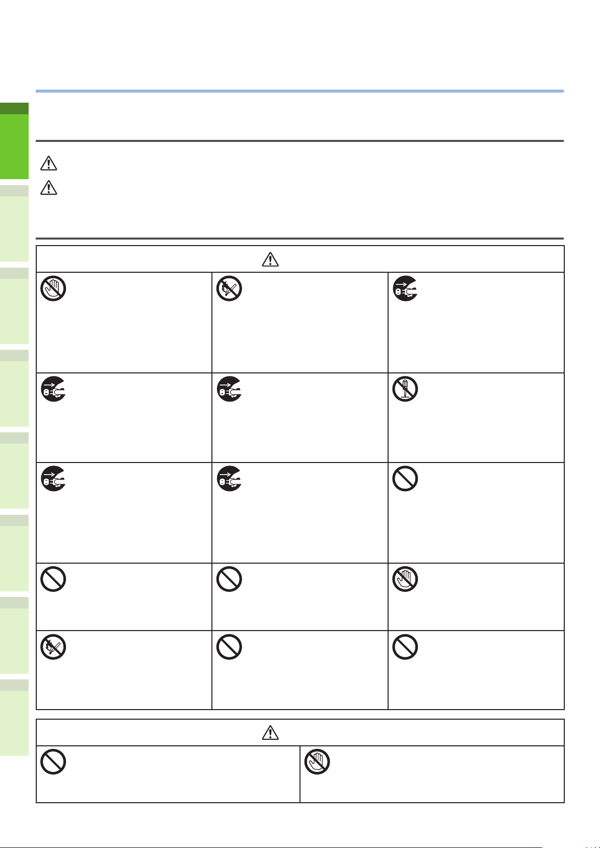
General cautions
2
3
4
5
6
Do not touch the safety
switch inside the machine.
Doing so may cause electric
shock when high voltage
occurs. In addition, gears can
rotate, which may result in
personal injury.
Pull the power plug out of
the socket and contact with
a customer’s service centre
when a liquid such as water
enters in the internal parts of
the machine.
Failure to do so may cause
re.
Unplug the power cord and
contact with a customer’s
service center if the machine
is dropped or the cover is
damaged.
Failure to do so may cause
electric shock and/or re
leading to personal injuries.
Do not insert materials in a
vent hole.
Doing so may cause electric
shock and/or re leading to
personal injuries.
Do not throw toner cartridges
and image drum cartridges
into re. Doing so may cause
dust explosion leading to
burns.
Do not use an inammable
spray near the machine.
Doing so may cause re since
there is an area heating up
within the machine.
Pull the power plug out of the
socket and remove foreign
materials such as clips when
they fall inside the machine.
Failure to do so may cause
electric shock and/or re
leading to personal injuries.
Unplug the power cord
periodically to clean plug
blades and root section
between the blades.
If the power plug remains
inserted for a long time, the
root section will get dusty,
and the plug may be shorted
out, which may cause re.
Do not put a cup with
liquids such as water on the
machine.
Doing so may cause electric
shock and/or re leading to
personal injuries.
Do not use a power cord, a
cable, or a ground wire other
than those that are indicated
in User's Manual.
Doing so may cause re.
Pull the power plug out of
the socket and contact with
a customer’s service centre
when the cover is unusually
hot, smoking, giving off
questionable odour, or
making a strange noise.
Failure to do so may cause
re.
Do not operate and/or
disassemble the machine
other than that directed in
User's Manual.
Doing so may cause electric
shock and/or re leading to
personal injuries.
Do not clean spilled toner
with a vacuum cleaner.
If cleaning spilled toner with
a vacuum cleaner, it may
catch re due to the sparks
from electric contact.
Toner spilled on the oor
should be wiped off with wet
cloth.
Do not touch the fuser and
other parts when opening the
cover of the machine.
Doing so may cause burns.
The operation of using UPS
(uninterruptible power
source) or inverters is not
guaranteed. Do not use
uninterruptible power source
or inverters.
Doing so may cause re.
Do not come closer to the paper’s exit area
when the power is turned on, while printing.
Doing so may result in personal injury.
Do not touch a damaged liquid-crystal display.
If liquid (liquid crystal) leaked from the liquid-
crystal display gets into the eyes or mouth, ush
with large amount of water. Follow the direction
from a doctor if necessary.
- 4 -
Page 5

When installing or moving
WARNING
For the U.S.A. and Canada
Multifunctional Digital Systems require 110 to 127 V, 10 A, 50/60 Hz electric power.
For the EU
Multifunctional Digital Systems require 220 to 240 V AC, 5 A, 50/60 Hz electric power.
Except the U.S.A., Canada and the EU
Multifunctional Digital Systems require 220 to 240 V AC, 5 A, 50/60 Hz electric power.
Do not use a power supply with a voltage other than that specied.
•
Avoid multiple connections in the same outlet. This could cause a re or give you an electric shock. If
you are considering increasing the number of outlets, contact an electrician.
Always connect this machine to an outlet with a ground connection to avoid the danger of re or
•
electric shock in case of short-circuiting. Contact your service representative for the details. Be sure
to use a 3-conductor, grounded wall outlet.
In areas, except the U.S. and Canada, where a 2-pin plug is used, the machine must be grounded for
safety. Never ground it to a gas pipe, a water pipe, or any other object not suitable for grounding.
Plug the power cord securely into the outlet. If it is not plugged in properly, it could heat up and
•
cause a re or give you an electric shock.
Do not damage, break or attempt to repair the power cord.
•
The following things should not be done to the power cord.
Twisting it
-
Bending it
-
Pulling it
-
Placing anything on it
-
Heating
-
Situating it near radiators or other heat sources
-
This could cause a re or give you an electric shock. If the power cord is damaged, contact your
dealer.
The socket outlet shall be near the equipment and be easily accessible.
•
Pull out the plug from the outlet more than once a year to clean around the prongs. Accumulating
•
dust and dirt could cause a re due to the heat released by electric leakage.
1
2
3
4
5
6
- 5 -
Page 6

CAUTION
When removing the plug from the outlet, do not pull the power cord. Always hold the plug when
WARNING
CAUTION
•
removing it from the outlet. If the power cord is pulled, the wires may break and this could cause a
re or give you an electric shock.
Make sure that the ventilation holes are not blocked.
•
If the temperature within the machine becomes too high, a re could result.
■ Other points
1
2
3
Be sure to x the power cable securely so that no one trips over it.
•
Adverse environmental conditions may affect the safe operation and performance of the machine,
•
and the machine could break down.
Avoid locations near windows or with exposure to direct sunlight.
-
Avoid locations with drastic temperature uctuations.
-
Avoid too much dust.
-
Avoid locations that suffer from vibration.
-
Make sure that the air is able to ow freely and that there is sufcient ventilation.
•
Without adequate ventilation, the unpleasant odor released by ozone will begin to dominate the
atmosphere.
When using the machine
Do not take off the cover of the equipment; otherwise you could be injured or get an electric shock.
•
Do not remove or connect the plug with wet hands, as this could give you an electric shock.
4
5
6
•
Do not place any container with liquid (ower vases, coffee cups, etc.) on or near the equipment.
•
This could cause a re or give you an electric shock.
Keep paper clips and staples away from the air vent. If not, a re could result or you could get an
•
electric shock.
If the machine becomes excessively hot, smoke comes out of it or there is an odd smell or noise,
•
proceed as follows.
Turn the main power switch OFF and remove the plug from the outlet, then contact your service
representative.
If the machine will not be used for more than one month, remove the plug from the outlet for safety
•
purposes during that time. If an insulation failure occurs, this could cause a re or give you an
electric shock.
Do not place heavy objects (8Kg/18lb. or more) on the document glass and do not press on it with
•
force. Breaking the glass could cause personal injury.
Do not place heavy objects (8Kg/18lb. or more) on the machine. If the objects fall off, this could
•
cause injury.
Do not touch the fuser unit or the metal area around it. Since they are very hot, you could be burned
•
or the shock could cause you to injure your hand in the machine.
Be careful not to let your ngers be caught when closing the tray. This could cause an injury.
•
Be careful not to let your ngers be caught between the equipment and the duplexing unit or
•
automatic duplexing unit. This could cause an injury.
Do not touch the metal portion of the guide plate in the duplexing unit or automatic duplexing unit as
•
it could burn you.
- 6 -
Page 7

Do not touch the hinge (= a connecting part) on the rear side of the Reversing Automatic Document
•
Feeder. This could catch and injure your ngers when you open or close the Reversing Automatic
Document Feeder.
Always keep hands and ngers clear of the nisher tray hinge, as the tray could move unexpectedly.
•
Failure to do so could result in injury to your hand and/or ngers.
Do not use the pulled out tray as steps. This could injure you if you fall.
•
When changing the angle of the control panel, be careful not to catch your hands in the gap between
•
the equipment and the control panel. This could cause personal injury.
Do not place objects of weighing 3.3 kg/7.3 lb. or more on the optional work table. Breaking the
•
work table could cause personal injury.
1
2
3
4
5
6
- 7 -
Page 8

■ Other points
WARNING
CAUTION
Be very careful to treat the touch panel gently and never hit it. Breaking the surface could cause
•
malfunctions.
Be sure to turn the power OFF when leaving the ofce or if there is a power outage. However, do not
•
turn the power OFF if the weekly timer is in use.
Be careful because the paper exit area and paper just after exiting are hot.
•
Do not place anything other than paper on the receiving tray. This could disturb a normal operation
•
1
2
3
and cause malfunctions.
Do not touch the photoconductive drum and transfer belt. This could cause image problems.
•
Do not open/close the covers and the MPT, or pull out the trays during printing.
•
During maintenance or inspection
Never attempt to repair, disassemble or modify the machine by yourself. You could cause a re or get
•
an electric shock.
Do not let liquids such as water and oil get into the machine when cleaning the oor. This could cause
•
a re and give you an electric shock.
Always keep the plug and outlet clean. Prevent them from accumulating dust and dirt. This could
•
cause a re and give you an electric shock due to the heat released by electric leakage.
Do not touch the stapling area. The actual needle point could cause you personal injury.
•
4
5
6
■ Other points
Do not use such solvents as thinner or alcohol when cleaning the surface of the machine.
•
This could warp the shape of the surface or leave it discolored.
-
When using a chemical cleaning pad to clean it, pay attention to any cautionary points.
-
- 8 -
Page 9

When handling supplies
CAUTION
Never attempt to incinerate toner cartridges and waste toner boxes. Dispose of used toner cartridges
•
and waste toner boxes in accordance with local regulations.
■ Other points
Read the user's manual carefully to replace the toner cartridge using the correct procedure. An
•
improper procedure could cause toner leakage or scattering.
Do not open the toner cartridge forcibly. This could cause toner leakage or scattering.
•
Keep the toner cartridge out of the reach of children.
•
If toner is spilt on your clothes, wash it off with cold water. If you use warm water, your clothes will
•
be permanently stained with toner because it will not come out .
1
If toner leaks from the toner cartridge, be careful not to inhale or touch it.
•
First-aid measures
If you inhale or touch toner, etc; carry out the following treatment.
Inhalation: Remove from exposure area to fresh air immediately. Contact a physician if there is
•
any difculty in breathing or other signs of distress.
Skin Contact: Wash with soap and water. Wash clothing before reuse. If irritation occurs or is
•
persistent, seek medical attention.
Eye Contact: Immediately ush eyes with plenty of water for at least 15 minutes. If irritation
•
persists, call a physician.
Ingestion: Dilute stomach contents with several glasses of water.
•
2
3
4
5
6
- 9 -
Page 10
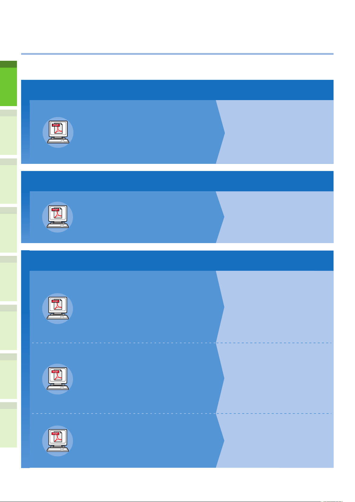
About the Manuals
1
•
The following user manuals are included with this product.
All guides are included in the software DVD-ROM.
Step
Read the Setup Guide first.
1
2
3
4
5
Installing the machine
Setup Guide (This manual)
Before using this machine, please read the
warnings and precautions to ensure the safe use of
this machine. We have also provided explanations
about necessary preparations such as installation
procedures and how to load the paper.
Step
After you have completed the setup of this equipment, read the Basic Guide.
2
Testing the machine, copier, fax, and scanner.
Basic Guide
This guide describes each function and basic
methods of use. In addition, we have provided
an explanation about how to register data in the
address book.
Step
Read these guides as necessary.
3
Making full use of the machine
Advanced Guide
This guide describes the use of convenient print
functions such as summarizing or sorting, and
advanced functions such as job memory, user
authentication, and access control. Explanations
are also provided about settings that can be
configured from the operator panel, as well as
network settings.
• Checking the Product
• Installing the Machine
• Turning Power ON/OFF
• About Paper
• About Document Copies
• Using Each Function
• Printing
• Copying
• Fax
• Scanning
• Utilities that can be used with this
machine
• Printing Operations
• Copying Operations
• FAX Operations
• Scanning Operations
• Registering Functions and Settings
• Setting Items/Printing Reports
When there is a problem or you need to repair the machine
6
Troubleshooting Guide
This guide describes how to deal with error
messages, such as those that accompany paper
jams, describes regular maintenance and
cleaning of the device, and explains how to
replace consumables. The machine specifications
are included as well.
Controlling/Setting from the Computer
Utility Guide
This guide describes the utility software for your
computer.
• Troubleshooting
• Maintenance
• List of Utilities
• About AddressBook Viewer
• About e-Filing Backup/Restore Utility
• About TWAIN Driver and File
Downloader
• About Remote Scan driver
• About WIA driver
- 10 -
Page 11

3
Step
Read these guides as necessary. (continue)
Using the TopAccess
TopAccess Guide
This guide describes how to use the
TopAccess.
Using the e-Filing
e-Filing Guide
This guide describes how to use the e-Filing.
• Overview
• [Device] Tab Page
• [Job Status] Tab Page
• [Logs] Tab Page
• [Registration] Tab Page
• [Counter] Tab Page
• [User Management] Tab Page
• [Administration] Tab Page
• [My Account] Tab Page
• Functional Setups
• e-Filing OVERVIEW
• OPERATIONS WITH THIS
EQUIPMENT
• OVERVIEW OF e-Filing WEB UTILITY
• HOW TO MANAGE USER
BOXES/FOLDERS
• MANAGING DOCUMENTS
• EDITING DOCUMENTS
• SYSTEM ADMINISTRATION
1
2
3
4
5
6
- 11 -
Page 12
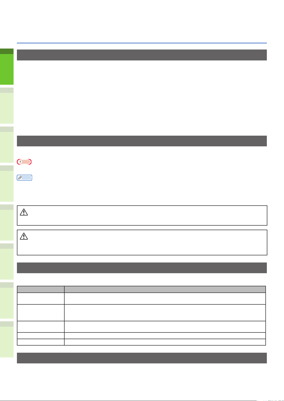
About This Manual
WARNING
CAUTION
•
Notation used in this manual
The following notations may be used in this manual.
If there is no special description, Windows 7 is used as Windows, Mac OS X 10.7 is used as Mac OS X, and
MB770dn is used as the machine for examples in this document.
Depending on your OS or model, the description on this document may be different.
1
About the Administrator
•
Administrator: The person who makes settings of this equipment and operates the equipment.
-
When the multiple persons use this equipment, the administrator is the person who manages the
equipment.
Network administrator: The person who manages the computer and the network.
2
-
Terms in this document
The following terms are used in this manual.
Note
3
Indicates important information on operations. Make sure to read sections with this mark.
•
Memo
Indicates additional information on operations. You should read sections with this mark.
•
&
Indicates where to look when you want to know more detailed or related information.
•
4
A warning provides additional information which, if ignored, may result in a risk of personal injury.
•
A caution provides additional information which, if ignored, may result in equipment malfunction or
5
•
damage.
Symbols in this document
The following symbols are used in this manual.
6
Symbols Description
[ ]
" "
[ ] button/key Indicates a hardware button on the operator panel or a key on the keyboard of the
> Indicates how to get to the item you want in the menu of this machine or the computer.
Your machine
Indicates menu names on the display screen.
•
Indicates menu, window, and dialog names on the computer.
•
Indicates messages and input text on the display screen.
•
Indicates le names on the computer.
•
Indicates reference titles.
•
computer.
Indicates a machine you want to use or select.
Illustrations in this document
The illustrations of the machine used in this document may be different from what you actually see on
your machine.
- 12 -
Page 13

Table of contents
Table of contents
About the Product Warranty ....2
Emergency rst aid .................. 3
Manufacturer ...........................3
Importer to the EU/Authorized
representative .........................3
Environmental information ......3
For Your Safety ........................ 4
When using the machine ......................6
During maintenance or inspection ..........8
When handling supplies .......................9
About the Manuals ................. 10
About This Manual .................12
Notation used in this manual ............ 12
Terms in this document ................... 12
Symbols in this document ................ 12
Illustrations in this document ........... 12
2 Installing the Machine ....25
Installation Conditions...........26
Unpacking and Installing the
Machine .................................29
Installing Additional Tray
Units ...................................... 33
Setting Up the Printer for Windows .... 37
Conguring the options ...................... 37
Setting the department code ..............38
Copying the PPD le for Windows ........40
Setting Up the Printer for Mac OS X ... 40
Conguring the printer on Mac OS X ...40
Connecting the Cables ...........44
Connecting the Network Cables ........ 44
Connecting the USB cable ................ 44
Connecting to the telephone line ....... 45
1
2
3
1 Checking the Product ......15
Name and Function of Each
Part .......................................16
Machine ......................................... 16
Components and Options ................. 18
Operator Panel ............................... 19
Adjusting the angle of the control
panel ............................................... 20
About the Operator Panel ......21
Description of the Touch Panel
Display .......................................... 21
Message displayed ............................21
Touch buttons ................................... 22
Adjusting the contrast of the touch
panel ............................................... 22
Simultaneous Functions (Multi-
operational) ................................... 22
Setting letters ................................ 23
3 Turning
Power ON/OFF ................48
Precautions about the Power
Supply ...................................49
Turning Power ON .................50
Power switch is OFF ........................ 50
Power switch is ON.......................... 50
Turning Power OFF ................51
Economizing power
consumption (energy saver
mode) when not using the
device ....................................52
4
5
6
Checking the Product ............. 24
- 13 -
Page 14

Table of contents
4 About Paper ....................53
About Paper ........................... 54
The Width and Length of the Paper .... 54
Supported Paper ............................. 55
Selecting the paper source and output
method for each paper type. ............ 58
Printable Areas of the Paper ............ 60
1
2
3
About Symbols ............................ 60
Storing Paper ................................. 61
How to Load the Paper ...........62
Loading the paper in the paper tray ... 62
Setting the paper size indicator......... 63
Loading the paper in the Large Capacity
Feeder........................................... 63
Using the Multi-Purpose Tray (MPT) ... 64
Preparation before Loading Envelopes in
the MP Tray ......................................64
Loading Paper ...................................66
6 Checking operations
using the device alone ....79
Test printing ..........................80
Checking copy operations ......81
Index ...................................82
Oki contact details ................84
Registering paper sizes to “OTHER”
size ............................................... 69
About Auto Tray Switching (Auto Tray
Switch Function) ............................. 70
4
Paper Output .........................71
Using the Facedown Stacker ............. 71
Using the Facedup Stacker ............... 71
5 About Document
5
6
Copies .............................72
About Document Copies ......... 73
Document Conditions ...................... 73
Readable Areas of the Document ...... 74
About Symbols ........................... 74
The Width and Length of the
Document ...................................... 75
Loadable Document Sizes ................ 75
Loading Documents ...............77
Loading the Documents ................... 77
Loading documents of various sizes (mix
documents). .................................. 78
- 14 -
Page 15

1
Checking the
Product
Name and Function of Each Part ……………… P.16
About the Operator Panel
Checking the Product
……………………………… P.24
………………………… P.21
1
2
3
4
5
6
Page 16
Name and Function of Each Part
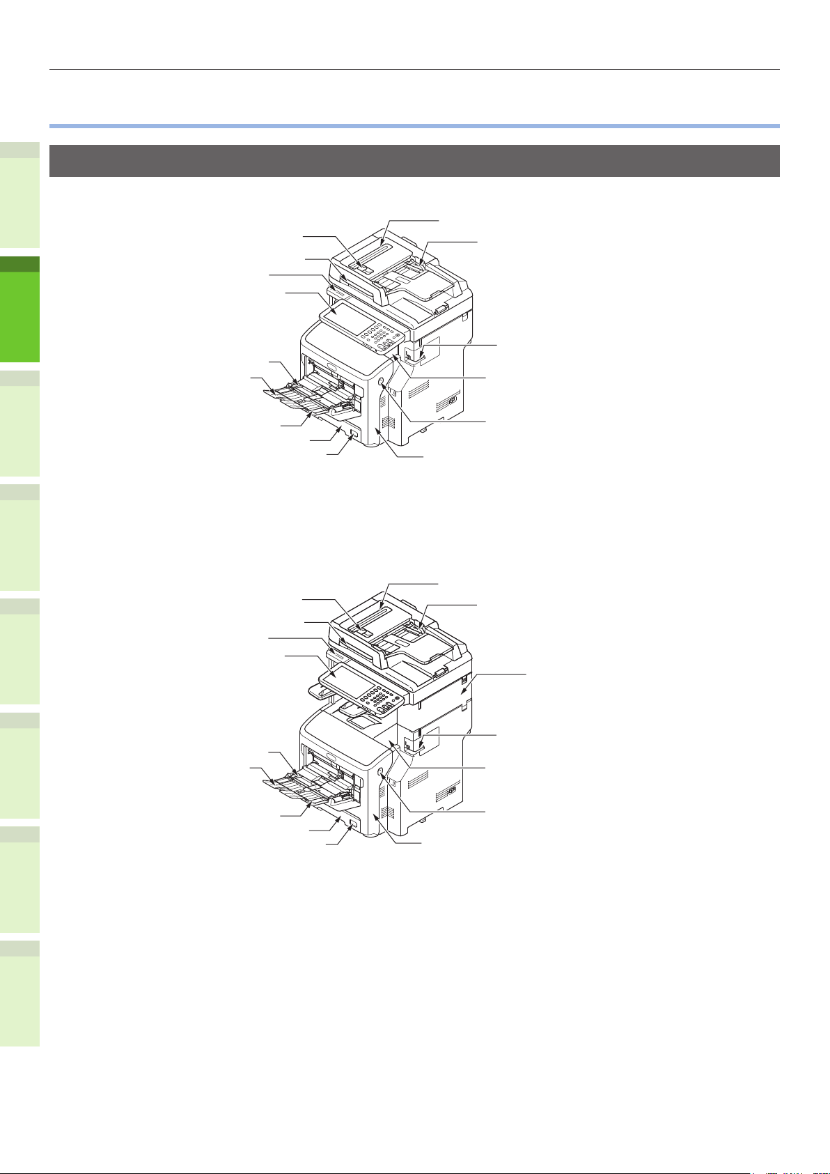
Name and Function of Each Part
•
Machine
Without the Inner nisher
1
2
RADF Cover Open Lever
Document Cover Lever
Handle
Operator Panel
Manual Guide
Paper Support
Scanner Part
Document Guide
Ofine Stapler
(when installing the ofine stapler)
Top Cover
3
With the Inner nisher
4
5
6
Multi-Purpose Tray (MPT)
Paper Tray 1
Paper Size Dial
RADF Cover Open Lever
Document Cover Lever
Handle
Operator Panel
Manual Guide
Paper Support
Multi-Purpose Tray (MPT)
Paper Tray 1
Paper Size Dial
Front Cover Open Lever
Front Cover
Scanner Part
Document Guide
Inner Finisher
Ofine Stapler
(when installing the ofine stapler)
Top Cover
Front Cover Open Lever
Front Cover
- 16 -
Page 17
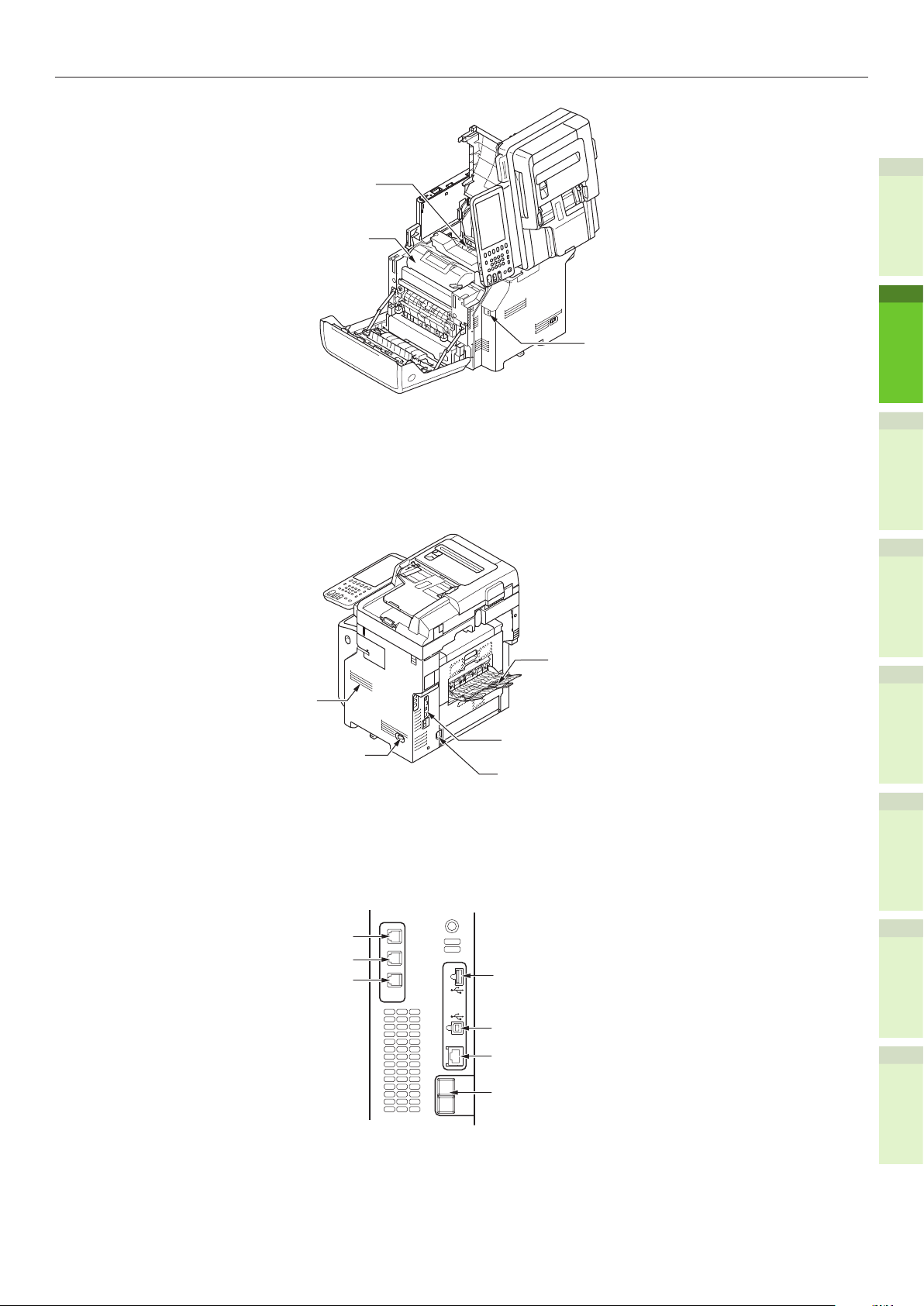
Fuser Unit
Print Cartridge
Name and Function of Each Part
1
USB Port
2
Vent
Power Switch
(HANDSET)
TEL Connector
LINE Connector
<Interface Part>
HANDSET
TEL
LINE
3
Faceup Stacker
4
Interface Part
Power Connector
5
6
ACC
LINE
COIN
- 17 -
USB Interface Connector
Network Interface Connector
(1000/100/10BASE)
COIN
Page 18
Name and Function of Each Part
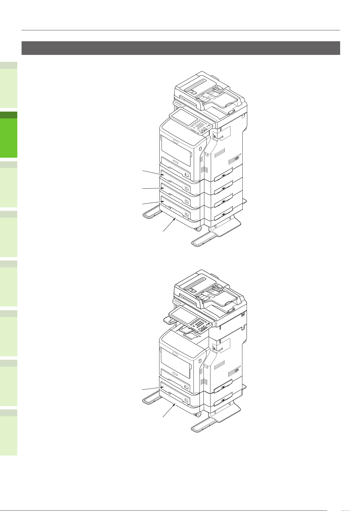
Components and Options
Without the Inner nisher
1
2
3
With the Inner nisher
4
5
Paper Tray 2
Paper Tray 3
Paper Tray 4
Caster unit
6
Paper Tray 2
Caster unit
- 18 -
Page 19
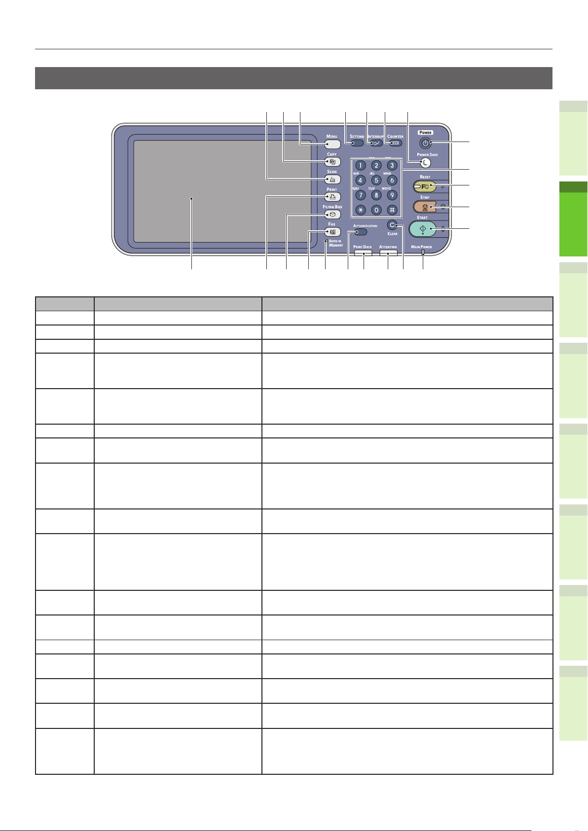
Operator Panel
Name and Function of Each Part
7654
8
9
FC
1415 131618 17
10
11
12
22
21
3
21 20 19
Number Name Function
1 [SCAN] button Use this button to access the scanning function.
2 [COPY] button Use this button to access the copying function.
3 [MENU] button Use this button to display frequently used templates.
4 [SETTING] button Use this button for paper size or media type setting of tray,
and registration of the copy, scan and fax settings including a
default setting change.
5 [INTERRUPT] button Use this button to interrupt print processing and perform a
copy job. The interrupted job is resumed through your pressing
this button again.
6 [COUNTER] button Use this button to display the counter.
7 [POWER SAVE] button Use this button for the equipment to enter the energy saving
mode.
8 [POWER] button Press to turn ON and OFF (i.e., shut down) the device power
supply. Further, when the device is in Energy Saver mode
(Super Sleep mode), press this button to restore the device to
regular standby mode.
9 Digital keys Use these keys to enter any numbers such as the number of
copies, telephone numbers or passwords.
10 [RESET] button When this button is pressed, all selected functions are cleared
and returned to the default settings. If the default setting is
changed on the control panel, and then copying, scanning,
faxing or similar is performed, the lamp of this button (orange)
blinks.
11 [STOP] button Use this button to stop any scanning and copying operations in
progress.
12 [START] button Use this button to start copying, scanning and faxing
operations.
13 MAIN POWER lamp This green lamp lights when the main power switch is ON.
14 [CLEAR] button Use this button to correct the numbers keyed in, such as the
number of copy sets.
15 ATTENTION lamp This orange lamp lights when an error occurs and some action
needs to be taken.
16 PRINT DATA lamp This blue lamp lights during reception of data such as print
data.
17 [AUTHENTICATION] button Use this button when the department code or user information
has been set. If this button is pressed after copying, etc.,
the next user needs to enter the department code or user
information.
1
2
3
4
5
6
- 19 -
Page 20
Name and Function of Each Part
CAUTION
Number Name Function
18 [DATA IN MEMORY] / LINE lamp This green lamp lights in the status of the fax data reception
and fax communication. The equipment can be operated even
while these lamps are lit.
19 [FAX] button Use this button to access the Fax / Internet Fax function.
20 [FILING BOX] button Use this button to access stored image data.
21 [PRINT] button Use this button to access the printing functions such as private
printing, in this equipment.
22 Touch panel Use this panel for the various settings of the copying, scanning
1
and Fax functions. This also displays messages, such as when
paper runs out or paper misfeeds occur.
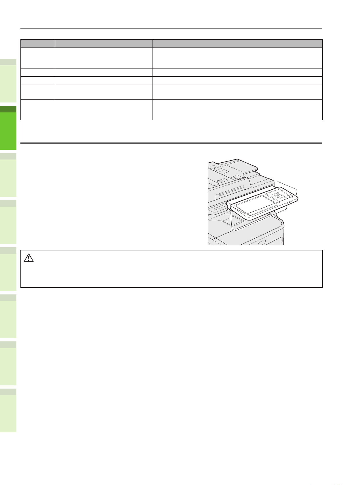
Adjusting the angle of the control panel
The angle of the control panel is adjustable at any angle from the horizontal position.
2
Without the Inner Finisher : Between 7 and 40 degree.
With the Inner Finisher : 7 degree xed.
3
4
When changing the angle of the control panel, be careful not to catch your hands in the
•
gap between the equipment and the control panel.
This could injure you.
5
6
- 20 -
Page 21
About the Operator Panel
5
6
3
4
1
2
About the Operator Panel
•
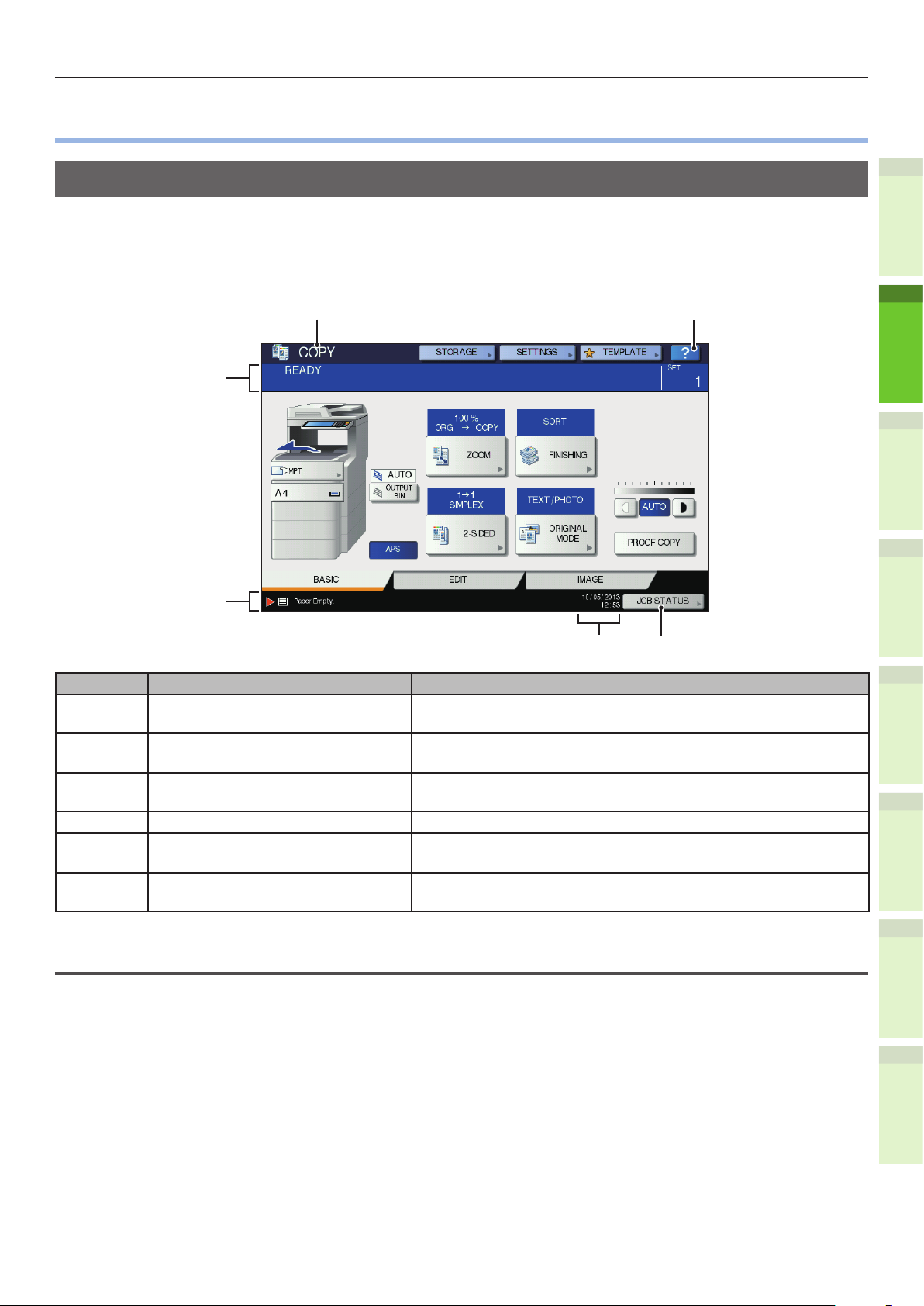
Description of the Touch Panel Display
When the power is turned ON, the basic menu for copying functions is displayed on this touch panel.
The status of the equipment is also displayed on the touch panel with messages and illustrations.
The menu shown at the time of turning the power ON can be changed to one for functions other than
copying, for example, Fax function. Contact your dealer for details.
1
2
Number Name Function
1 Function display The function being used, such as copying or faxing, is
displayed.
2 [?] (HELP) button Use this button to view the explanation of each function or the
buttons on the touch panel.
3 [JOB STATUS] button This indicates the processing status of copy, fax, scan or print
jobs, and also allows you to view their performance history.
4 Date and time The present date and time are displayed.
5 Alert message indication area This shows alert messages such as when the toner cartridge
must be replaced.
6 Message indication area The explanation of each operation or the current status is
displayed in message form.
Message displayed
The following information appears on the touch panel:
3
4
5
6
Equipment status
•
Operational instructions
•
Cautionary messages
•
Reproduction ratios
•
Number of copy sets
•
Paper size and amount of paper remaining in a selected tray
•
Date and time
•
- 21 -
Page 22

About the Operator Panel
Touch buttons
Press these buttons on the touch panel lightly to set various functions.
Adjusting the contrast of the touch panel
You can set the contrast of the touch panel in the SETTING menu entered by pressing the [SETTING]
button on the control panel.
1
Simultaneous Functions (Multi-operational)
This machine can perform operations simultaneously. For details, refer to the following table.
Note
The operator panel cannot be used when the machine is scanning a document.
•
The performance of individual operations may deteriorate when multi-operational.
2
3
•
Sometimes simultaneous operations are not possible, such as when there is not enough free space in the memory.
•
:Operation Available ×:Operation Unavailable
Second Operation
Copy Fax Send
First Operation
Copy ×
Fax Send
Fax Receive ×*1
Scan to Email/Network
PC/ USB Memory
Scan to Remote PC × ×
Print from Computer
*2
*3 *3
*2
*3 *3
∆
:You can copy if you press the [INTERRUPT] button.
Fax
Receive
×
×
Scan to Email/
Network PC/ USB
Memory
*3
× ×
Scan to
Remote
4
*1 You can copy as long as the printing of a received fax has not started.
*2 If one operation is communicating, the second operation will be suspended until the rst is
completed.
PC
Print from
Computer
*3 After the printing of the rst operation is completed, the printing of the second operation starts.
5
6
- 22 -
Page 23
About the Operator Panel
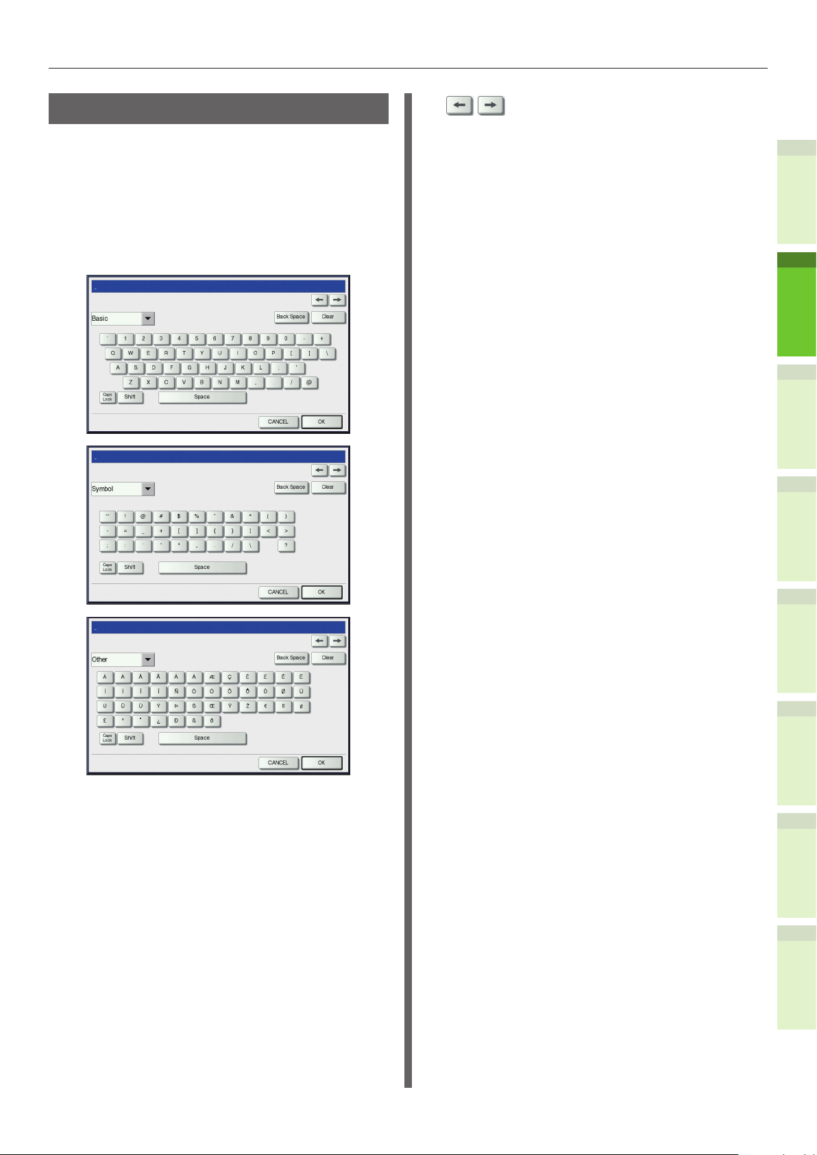
Setting letters
The following menu is displayed when the entry
of any letter is required for scanning or e-Filing,
etc.
Use the buttons on the touch panel for letter
entry.
After entering the letters, press [OK]. The menu
will be changed.
: Press these to move the
cursor.
[Back Space]: Press this to delete the letter
before the cursor.
[Clear]: Press this to delete all letters
entered.
[CANCEL]: Press this to cancel the entry
of letters.
[OK]: Press this to x all entered
letters.
1
2
3
The following buttons are used for letter entry.
[Basic]: Press this to access the basic
keys.
[Symbol]: Press this to access the symbol
keys.
[Other]: Press this to access the special
keys.
[Caps Lock]: Press this to switch capital
letters and small letters.
[Shift]: Press this to enter capital
letters.
[Space]: Press this to enter a space.
4
5
6
- 23 -
Page 24
Checking the Product
CAUTION
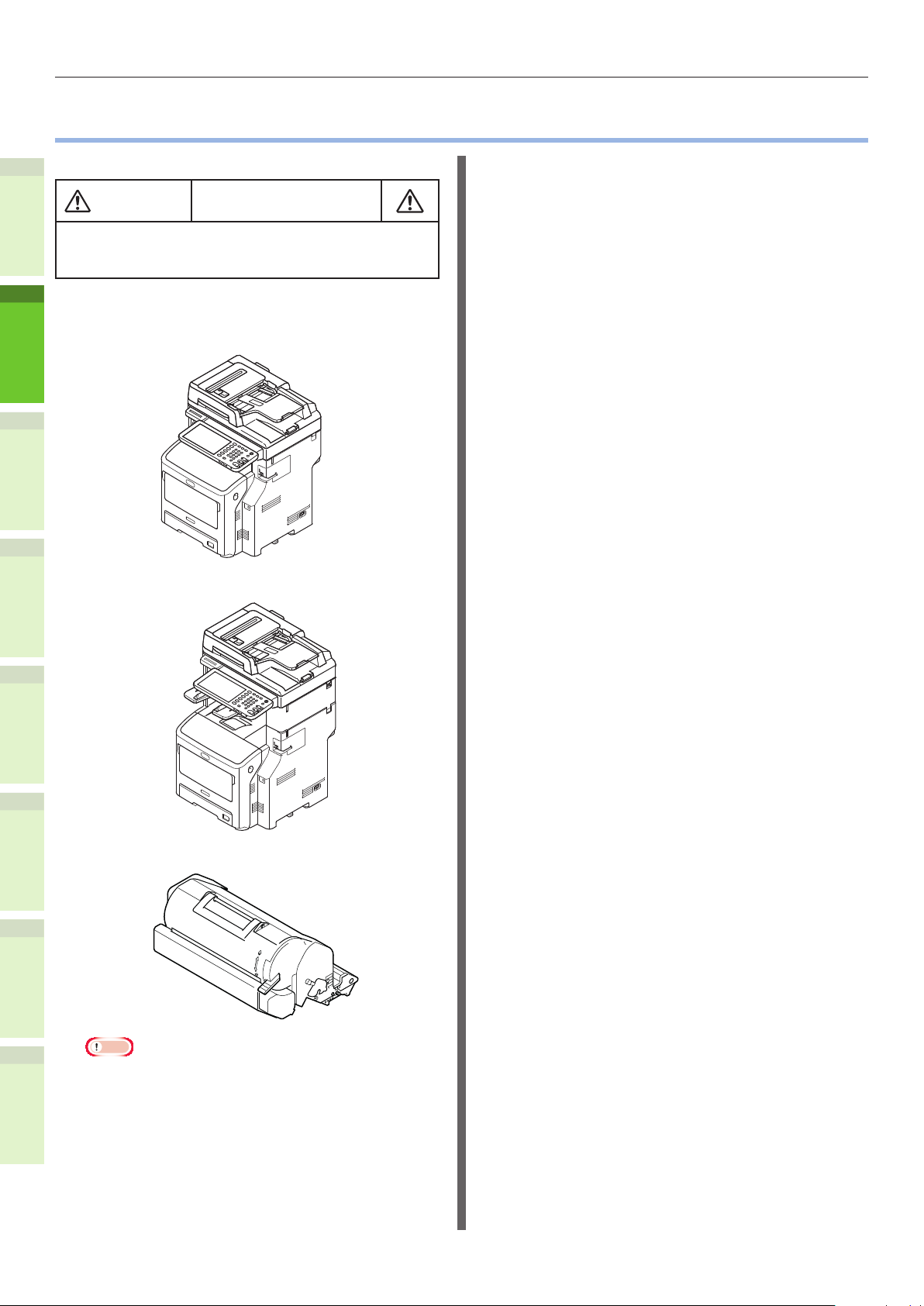
Checking the Product
•
Check that you have everything shown below.
May cause injury!
At least three people are needed to safely lift the
•
machine due to its 60 kg (132.3 lb.) weight (with
the Inner Finisher).
1
2
3
4
Machine
•
Without the Inner nisher
With the Inner nisher
5
Print cartridge
•
6
Note
The print cartridge is installed inside the machine.
•
The print cartridge for the ES/MPS series are divided
•
into an image drum and a toner cartridge.
software DVD-ROM
•
Power Cord
•
Telephone Line Cable
•
- 24 -
Page 25

2
Installing the
Machine
Installation Conditions …………………………… P.26
Unpacking and Installing the Machine
Installing Additio
Connecting the Cables
nal Tray Units
……………………………… P.44
………………… P.33
……… P.29
1
2
3
4
5
6
Page 26

Installation Conditions
WARNING
CAUTION
Installation Conditions
•
■ Operating Environment
Your machine must be placed in the following
environment:
Temperature: 10 - 32 °C
Humidity:
1
Maximum wet bulb
temperature
Note
Avoid condensation. It may cause a malfunction.
•
If your machine is in a location where the humidity is 30%
2
3
•
RH or less, use a humidier or antistatic mat.
20% - 80% RH
(relative humidity)
25 °C
■ Installation Precautions
Do not install the machine near high temperatures
•
or re.
Do not install the machine in places where
•
chemical reactions are performed, such as a
laboratory.
Do not install the machine near ammable liquids,
•
such as alcohol and paint thinner.
Do not install the machine where young children
•
might get hands or ngers caught in the
machine’s parts.
Do not install the machine in an unstable place,
•
such as a shaky stand or uneven surfaces.
Do not install the machine in places with high
•
humidity, dust, or direct sunlight.
Do not install the machine in places with briny air
•
or corrosive gas.
Do not install the machine in places which
•
experience a lot of vibration.
Do not install in places where the ventilation holes
•
of the machine will be blocked.
4
5
6
Do not place the machine directly on high pile
•
rugs or carpets.
Do not install the machine in a closed room with
•
poor ventilation.
If using the machine in a small room for extended
•
periods, make sure that the room is well
ventilated.
Install the machine away from strong magnetic
•
elds and sources of noise.
Install the machine away from monitors or TVs.
•
When moving the machine, make sure that you
•
support it from both sides.
At least three people are needed to safely lift the
•
machine, due to its weight.
If you intend to perform a large print job or use
•
the machine continuously for extended periods,
make sure that the room is well ventilated.
- 26 -
Page 27

Installation Conditions
■ Installation Space
Place the machine on a at surface that is wide
enough to accommodate the feet of the machine
securely.
Allow for enough space around the machine.
Top View
•
20cm (7.9 inch)
(96.5cm
(37.0 inch))
60cm
(23.6 inch)
20cm (7.9 inch)
Side View
•
(213cm (83.9 inch))
100cm (39.4 inch)
60cm (23.6 inch)
Top View (when installing the optional tray)
•
20cm (7.9 inch)
(124.5cm
(49 inch))
60cm
(23.6 inch)
100cm (39.4 inch)
20cm (7.9 inch)
Side View (when installing the optional tray)
•
60cm (23.6 inch)
1
2
3
(127cm
(50 inch))
Side View (With the inner nisher)
•
60cm (23.6 inch)
(143cm
(56.3 inch))
(184cm (72.4 inch))
4
5
6
- 27 -
Page 28

Installation Conditions
Side View (when installing the optional tray
•
with the inner nisher)
1
2
60cm (23.6 inch)
(184cm (72.4 inch))
3
4
5
6
- 28 -
Page 29

Unpacking and Installing the Machine
Unpacking and Installing the Machine
•
Remove the protector.
1
Note
The box, packaging, and cushioning material are
•
needed to transport the machine. Do not dispose of
these items.
(1) Remove the machine from
the box, and then remove the
cushioning.
Note
Three people are needed to safely lift this
•
machine.
Cushioning
(4) Remove the protective tape.
Protective tape
1
2
Protective tape
(5) Return the document holder
cover to its original position.
3
Document
Holder Cover
Cushioning
(2) Remove the protective tape from
the back of the machine.
Protective Tape
(3) Open the document holder cover.
Document Holder
Cover
4
5
6
- 29 -
Page 30

Unpacking and Installing the Machine
Set the print cartridge.
2
(3) For the ES/MPS series, remove
the protective tape and orange
(1) Hold the handle and lift the
stopper.
scanner part.
Scanner
part
1
Handle
2
(2) Insert your nger into the recess
on the right side of the machine
and pull the front cover open
(4) Turn the blue lever of the print
cartridge fully in the direction of
the arrow.
lever to open the front cover
3
forward.
Note
Open the front cover gently. If you open it
•
rapidly, the MP tray may open.
Print Cartridge
Blue Lever
4
5
Front Cover
Open Lever
Front Cover
(5) Open the top cover.
Top Cover
6
- 30 -
Page 31

Unpacking and Installing the Machine
(6) Pull out the orange stopper from
the fuser unit.
Orange stopper
(7) Close the top cover.
Top Cover
(9) Return the scanner part to its
original position.
Load paper in the paper tray.
3
(1) Open the paper tray.
1
2
3
(8) Close the front cover.
Front Cover
(2) Adjust the paper stop and paper
guide to match the paper size.
Paper Stop
Paper Guide
Plate
Paper
Guide
Note
Squeeze the paper stop to adjust its position.
•
Do not remove the cork that is attached to the
•
plate.
4
5
6
- 31 -
Page 32

Unpacking and Installing the Machine
(3) Flex the stack of paper back and
(6) Close the paper tray.
forth a few times. Then, make a
neat stack by straightening its
edges against a level surface.
1
2
(4) Load the paper with the side to
Note
Using paper that is not recommended may
•
cause the machine to malfunction.
& For details about paper, see "Supported Paper"
(P.55).
be printed on face down.
3
The side to be printed
on should be face down.
Set the direction
of the paper.
4
Note
Load the paper, making sure that it does not
•
exceed the mark on the paper guide. (300
pieces at 80g/m2)
Mark
5
(5) Display the size of the paper to
be loaded on the indicator then
insert the indicator.
6
- 32 -
Page 33

Installing Additional Tray Units
CAUTION
Installing Additional Tray Units
•
Installing additional tray units will increase the amount of paper you can load. You can install a
maximum of three additional trays. One tray can hold 530 sheets of paper at 80 g/m2 (20 lb.). By
adding an extra tray to the standard tray and the multi-purpose tray, you can print up to 1160 pages
continuously.
Memo
The additional trays are called “Tray 2”, “Tray 3” and “Tray 4”.
•
Additional Tray Unit Spacer Caster Unit
Caster Unit
1
2
Model Name:N22405A
Note
Up to three tray units can be added to the equipment
•
without the Inner Finisher. For the equipment with the
Inner Finisher, up to two tray units including the spacer
can be added.
Place the spacer under the additional tray unit.
•
May cause injury!
To use the Additional Tray, always use the
•
Caster Unit, and make sure to attach the
anti-tip feet and joint parts.
Open the box and remove the
1
additional tray. Remove the
cushioning and protective materials.
Anti-tip Foot
Side (2)
Anti-tip Foot
Rear (2)
Turn OFF the power to the machine,
2
Anti-tip Foot
Cover (2)
Cover (2)
Anti-tip Foot
(2)
Screws (22)Anti-tip Foot
and remove the power cord and
cables.
Note
If you leave the power ON, you may damage the
•
machine.
& For details about how to turn OFF the machine, see
“Turning Power OFF” (P.51).
3
4
5
6
- 33 -
Page 34

Installing Additional Tray Units
Attach the caster unit.
3
Note
When the casters are not used, this step is not
•
necessary.
(1) Attach the anti-tip feet (both
sides and front) with four
screws.
1
Note
Attachment directions are different for the left side
•
and the right side.
When you tighten the bottom screws, attach the
•
anti-tip foot to the location where a screw does
not incline.
*
You can attach the screws to Case1 and Case2.
As the screw inclines when you tighten the screw
in Case3, lift the anti-tip foot and attach the
screw to Case2.
Case 1 Case 2 Case 3
Screw Hole
Screw Hole
Screw Hole
OK OK NG
2
(3) Tighten the anti-tip foot covers
(both sides) and anti-tip feet
with two screws each.
3
(2) Put the bottoms of the anti-tip
feet (both sides) on the oor,
align the sides to the cabinet
and tighten them with the two
screws each.
4
Screw Hole
(4) Align the anti-tip foot cover
5
Note
Do not tighten the upper screws.
•
Screw Hole
(rear) to the rear side of the
anti-tip foot.
6
- 34 -
Page 35

Installing Additional Tray Units
CAUTION
(5) Put the bottoms of the anti-tip
feet on the oor and tighten
them with three screws.
Attach the screw in the middle of the
oval cutout and tighten the screw.
Attach the additional tray and
4
spacer to the caster unit.
(1) Insert the posts of the cabinet to the
bottom holes of the tray.
Put the machine on the additional
5
tray unit.
May cause injury!
At least three people are needed to
•
safely lift the machine due to its 50 kg
(110 lb.) weight.
(1) Align the rear sides of the
machine and the additional
tray unit and place the machine
quietly.
1
2
3
Tra y s
Spacer
Post
(2) Fix the tray with the joint-option
and tighten the screws with the
screw-knob.
JointOption
Screw-Knob
(2) Fix the additional tray unit with
the joint-option, and tighten the
screw with the screw-knob.
Joint Option
Screw Knob
4
5
6
Tighten them on the both sides.
- 35 -
Page 36

Installing Additional Tray Units
(3) Press down the lock levers of
the additional tray unit’s front
casters and lock the casters.
1
2
Note
For prevention of fall, note the following points in
•
transporting the equipment and printing.
Do not push the machine when the scanner
-
3
part is opened.
Do not push the machine’s rear side when
-
one or more paper trays are pulled out.
4
5
Do not press the paper tray when it is pulled
-
out.
6
- 36 -
Page 37

Installing Additional Tray Units
Setting Up the Printer for Windows
Congure the additional tray by using the printer
driver.
Before printing, you have to congure the
following options:
Conguration Settings
•
To use optional devices such as optional trays
or the Finisher, you must rst congure these
devices. The features of these optional devices
are not available unless you inform the system
that the optional devices are installed.
Before printing, you can congure the following
option if necessary:
Department Code
•
You can use department codes to manage
each job. For example, a system administrator
can check how many sheets of copies a certain
department has made. When the department
code is enabled, you are prompted to enter a
department code before printing. If you enter
the department code in the corresponding
eld in advance, you can print without having
to do this every time. Ask your administrator
about the codes. When SNMP communication
between the equipment and your computer is
enabled, you are also prompted to enter the
code before printing.
Conguring the options
To use this equipment properly, you need to save
the conguration of the options installed on the
[Device Settings] tab menu after you installed
the printer drivers. In the default setting, you
can obtain the conguration data of options
installed automatically by opening the [Device
Settings] tab menu. If SNMP communication
between this equipment and your computer is
not available, or you want to congure options
manually, see the following page:
Memo
When SNMP communication between this equipment and
•
your computer is enabled, you can retrieve the option
conguration information by clicking [Update Now].
■ Conguring options manually
If SNMP communication between this equipment
and your computer is not available:
Setting the [Device Settings] tab
manually
Note
You need to log in to Windows with the “Administrator”
•
privilege.
Click [Start] menu and select
1
[Devices and Printers].
The Printers folder appears.
Select the printer driver for this
2
equipment, and then click [Printer
properties] in the [File] menu.
The printer driver properties dialog box appears.
1
2
3
4
5
6
& P.37 "Conguring options manually"
- 37 -
Page 38

Installing Additional Tray Units
If the [File] menu is not displayed, press
•
[Alt].
If the dialog box displayed does not
•
allow the printer driver properties to be
changed, follow the procedure below.
For Windows 7, some tab menus
-
have a button in the printer driver
properties. To change the properties,
1
2
3
click on it. If the properties cannot
be changed, ask your network
administrator.
To change a network-installed printer
•
driver, the administrator privilege is
necessary. Ask your network administrator
for details.
Display the [Device Settings] tab
menu, and set the following options.
3
4
Set the following options and click
5
[OK].
Tray 1 — Select the size and type of paper that is
loaded in the 1st Tray.
Tray 2 — Select the size and type of paper that is
loaded in the 2nd Tray.
Tray 3 — Select the size and type of paper that is
loaded in the 3rd Tray.
Tray 4 — Select the size and type of paper that is
loaded in the 4th Tray.
LCF — Select the size and type of paper that is
loaded in the Large Capacity Feeder (LCF).
MPT — Select the type of paper that is loaded in
the Multi-Purpose Tray (MPT).
Override Application Paper Source Settings
— Select this check box to use the paper source
setting in the printer driver rather than the
application setting.
Memo
Setup items differ depending on the model and the
5
Model Selection — This sets the model type.
The setup items of the printer driver are changed
according to the model selected.
Option — This option sets whether the following
optional devices are installed.
6
4
Trays — This sets whether or not the Paper
•
Feed Unit is installed.
Finisher — This sets whether or not the Inner
•
Finisher is installed.
Memo
Setup items differ depending on the model and the
•
option conguration.
Click [Tray Settings].
The [Tray Settings] dialog box appears.
•
option conguration.
Click [Apply] or [OK] to save
6
settings.
Setting the department code
When this equipment is managed by department
codes, you have to enter yours on the printer
driver.
This allows a network administrator to check the
number of copies printed by specic department
members. Also users can check who submitted
the print jobs, by touch panel display and
monitoring tools.
Please ask your administrator whether you
should enter the department code.
- 38 -
Page 39

Installing Additional Tray Units
Note
When the User Management setting is enabled, it is
•
used to manage a print job instead of the Department
Code Management setting. In this case, a user name
that has been entered to log in to your computer is
used for the authentication of the print job. Therefore,
you do not need to set your department code to the
printer driver but you must register your user name in
advance. If your user name is not registered, the print
job is processed as an invalid one according to the User
Authentication Enforcement setting. Also if a print job is
sent in RAW format, it is processed according to the RAW
Print Job setting. For more information about the User
Authentication Enforcement setting or the RAW Print Job
setting, refer to the TopAccess Guide.
Memo
How the equipment performs printing for an invalid
•
department code print job, for which an invalid
department code is specied, varies depending on the
Invalid Department Code Print Job setting that can be set
in the TopAccess Administrator mode and whether SNMP
communication is enabled or not.
When SNMP communication is enabled and Invalid
-
Department Code Print Job is set to [Store to invalid
job list], an error message will be displayed when an
invalid department code is entered.
When SNMP communication is disabled and Invalid
-
Department Code Print Job is set to [Store to invalid
job list], the invalid department code print job will be
stored in the invalid department code print job list
without printing.
When the Invalid Department Code Print Job is set to
-
[Print], the invalid department code print job will be
printed.
When the Invalid Department Code Print Job is set to
-
[Delete], the invalid department code print job will be
deleted.
A department code needs to be entered every time you
•
begin printing. If you have to use a different department
code for each print job, enter it when you begin printing.
Select the printer driver of
2
this equipment, and then click
[File] menu and select [Printing
Preferences].
If the [File] menu is not displayed, press
•
[Alt].
The printing preferences dialog box
•
appears.
Display the [Others] tab menu and
3
enter your department code in the
[Department Code] box.
1
2
3
4
Entering department code
Click [Start] menu and select
1
[Devices and Printers].
The Printers folder appears.
In the [Department Code] box, you can enter a
department code within 63 characters.
Memo
A department code must consist of one-byte characters
•
such as numbers from 0 to 9, letters of the alphabet
from A to Z (both capital and small ones), a hyphen
(-), an underscore (_), and a period (.).
Click [Apply] or [OK] to save the
4
settings.
5
6
- 39 -
Page 40

Installing Additional Tray Units
Copying the PPD le for Windows
The software DVD-ROM contains a machine
description le for popular Windows applications.
For applications not allowing the automatic
installation of PPD les, copy the PPD le to
a proper directory in order to enable printer-
specic settings in the [Print] dialog box or the
[Page] Setup dialog box.
1
Setting Up the Printer for Mac OS X
Conguring the printer on Mac OS X
After you copy the PPD le to the library folder
2
in the System Folder, you can congure the
machine.
The equipment supports the following Macintosh
Printing Services:
LPR printing
3
•
& P.40 “Conguring LPR printing”
Click [+].
2
Click [IP] and specify the items as
3
described below.
IPP printing
•
& P.41 “Conguring IPP printing”
Bonjour printing
•
& P.42 “Conguring Bonjour printing”
4
5
6
Memo
These Macintosh Printing Services are available when the
•
equipment and your computer are connected over TCP/IP
network.
■ Conguring LPR printing
Open System Preferences and click
1
[Print & Scan].
Protocol: Line Printer Daemon - LPD
Address: <IP address or DNS name of this
equipment>
Queue: print
Name: <Any Name>
Location: <Any Name>
Print Using: MB770_ES7170 MFP_
MPS5502mb-X7
Memo
For MAC OS X 10.4.x to 10.6x, select MB770_ES7170
•
MFP_MPS5502mb-X4.
In the [Name] box, the name that is entered in the
•
[Address] box is automatically displayed.
The way to select the PPD le differs depending on
•
countries or regions as follows:
For North America
-
Even when you enter the IP address or DNS name
of this equipment in the [Address] box, the correct
PPD le is not selected in the [Print Using] box.
Therefore, select [Other] in the [Print Using] box,
and select the PPD le MB770_ES7170 MFP_
MPS5502mb-X7 from the [/Library/Printers/PPDs/
Contents/Resources/en.lproj] folder.
- 40 -
Page 41

For the UK
-
When you enter the IP address or DNS name of
this equipment in the [Address] box, the correct
PPD le is automatically selected in the [Print
Using] box. If the correct PPD is not automatically
selected, select [Select a driver to use] and
choose the PPD le displayed in the list.
Click [Add].
4
The [Installable Options] window appears.
Installing Additional Tray Units
■ Conguring IPP printing
When you want to setup IPP print queue in the
Mac OS X, follow the procedures below.
Open System Preferences and click
1
[Print & Scan].
Set the following options.
5
Model Selection
•
— Choose this for using your model.
Finisher
•
Not Installed — Select this if a nisher is
not installed.
Inner Finisher (Tray 1) — Select this
when the Inner Finisher is installed.
Note
Even if you choose [Not Installed] for the Finisher
•
option during print settings, the nisher options such
as stapling can be selected. If you select the nisher
options for printing but the nisher is not installed,
nisher settings will be ignored and printing will be
performed correctly.
Trays
•
Tray 1
Select this when the tray 1 is installed.
Tray 1 & Tray 2
Select this when the tray 1 and 2 are
installed.
Tray 1, 2 & Tray 3
Select this when the tray 1, 2 and 3 are
installed.
Tray 1, 2 & Tray 3, 4
Select this when the tray 1, 2, 3 and 4 are
installed.
Tray 1 & LCF
Select this when the tray 1 and LCF are
installed.
Tray 1, 2 & LCF
Select this when the tray 1, 2 and LCF are
installed.
Click [+].
2
Click [IP] and specify the items as
3
described below.
1
2
3
4
5
6
Click [OK].
6
The printer is added to the Printer List.
- 41 -
Page 42

Installing Additional Tray Units
Protocol: Line Printer Daemon - LPD
Address: <IP address or DNS name of this
equipment>
Queue: print
Name: <Any Name>
Location: <Any Name>
Print Using: MB770_ES7170 MFP_
MPS5502mb-X7
1
2
3
4
4
5
Memo
For MAC OS X 10.4.x to 10.6x, select MB770_ES7170
•
MFP_MPS5502mb-X4.
In the [Name] box, the name that is entered in the
•
[Address] box is automatically displayed.
The way to select the PPD le differs depending on
•
countries or regions as follows:
For North America
-
Even when you enter the IP address or DNS name
of this equipment in the [Address] box, the correct
PPD le is not selected in the [Print Using] box.
Therefore, select [Other] in the [Print Using] box,
and select the PPD le MB770_ES7170 MFP_
MPS5502mb-X7 from the [/Library/Printers/PPDs/
Contents/Resources/en.lproj] folder.
For the UK
-
When you enter the IP address or DNS name of
this equipment in the [Address] box, the correct
PPD le is automatically selected in the [Print
Using] box. If the correct PPD is not automatically
selected, select [Select a driver to use] and
choose the PPD le displayed in the list
Click [Add].
The Installable Options window appears.
Set the following options.
6
1
Inner Finisher (Tray 1) — Select this
when the Inner Finisher is installed.
Note
Even if you choose [Not Installed] for the Finisher
•
option during print settings, the nisher options such
as stapling can be selected. If you select the nisher
options for printing but the nisher is not installed,
nisher settings will be ignored and printing will be
performed correctly.
Trays
•
Tray 1
Select this when the tray 1 is installed.
Tray 1 & Tray 2
Select this when the tray 1 and 2 are
installed.
Tray 1, 2 & Tray 3
Select this when the tray 1, 2 and 3 are
installed.
Tray 1, 2 & Tray 3, 4
Select this when the tray 1, 2, 3 and 4 are
installed.
Tray 1 & LCF
Select this when the tray 1 and LCF are
installed.
Tray 1, 2 & LCF
Select this when the tray 1, 2 and LCF are
installed.
Click [OK].
The printer is added to the Printer List.
■ Conguring Bonjour printing
Open System Preferences and click
[Print & Scan].
5
6
Model Selection
•
— Choose this for using your model.
Finisher
•
Not Installed — Select this if a nisher is
not installed.
- 42 -
Page 43

Installing Additional Tray Units
Click [+].
2
Click [Default] and select the MFP of
3
the Bonjour connection displayed in
the list.
Set the following options.
5
Model Selection
•
— Choose this for using your model.
Finisher
•
Not Installed — Select this if a nisher is
not installed.
Inner Finisher (Tray 1) — Select this
when the Inner Finisher is installed.
Note
Even if you choose [Not Installed] for the Finisher
•
option during print settings, the nisher options such
as stapling can be selected. If you select the nisher
options for printing but the nisher is not installed,
nisher settings will be ignored and printing will be
performed correctly.
1
2
3
Memo
In the [Name] box, the device name that you
•
selected in the list is automatically displayed.
The way to select the PPD le differs depending on
•
countries or regions as follows:
For North America
-
Even when you select the equipment from the list,
the correct PPD le is not selected in the [Print
Using] box. Therefore, select [Other] in the [Print
Using] box, and select the PPD le MB770_ES7170
MFP_MPS5502mb-X7 from the [/Library/Printers/
PPDs/Contents/Resources/en.lproj] folder.
For the UK
-
When you select the equipment from the list,
the correct PPD le is automatically selected in
the [Print Using] box. If the correct PPD is not
automatically selected, select [Select a driver to
use] and choose the PPD le displayed in the list.
Click [Add].
4
The [Installable Options] window appears.
Trays
•
Tray 1
Select this when the tray 1 is installed.
Tray 1 & Tray 2
Select this when the tray 1 and 2 are
installed.
Tray 1, 2 & Tray 3
Select this when the tray 1, 2 and 3 are
installed.
Tray 1, 2 & Tray 3, 4
Select this when the tray 1, 2, 3 and 4 are
installed.
Tray 1 & LCF
Select this when the tray 1 and LCF are
installed.
Tray 1, 2 & LCF
Select this when the tray 1, 2 and LCF are
installed.
Click [OK].
6
The printer is added to the Printer List.
4
5
6
- 43 -
Page 44

Connecting the Cables
Connecting the Cables
•
Connecting the Network
Connecting the USB cable
Cables
Prepare a USB cable.
1
Procure a network cable and a hub.
1
1
2
Note
A network cable and hub are not provided with
•
this product. Procure a network cable (category 5,
twisted pair, straight) and a hub separately.
<Network Cable> <Hub>
2
Connect the machine to the
2
network.
3
4
(1) Insert the network cable into the
network interface connector of
the machine.
(2) Insert the network cable to the
hub.
Note
A USB cable is not provide with this product. Procure
•
a USB 2.0 cable separately.
Use a USB 2.0 Hi-Speed cable for a USB 2.0 Hi-
•
Speed connection.
Connect the USB cable.
(1) Insert the end of the USB cable
into the USB interface connector
of the machine.
Note
Be careful not to insert the USB cable into the
•
network interface connector. This may cause
damage.
(2) Insert the end of the USB cable
into the USB interface connector
of the computer.
5
Network
Interface
Connector
6
USB Interface
Connector
- 44 -
Page 45

Connecting to the telephone line
The telephone line cable connection method
varies depending on the operating environment
you are using. Make the following connection
while taking into consideration your personal
environment.
Note
Connection is not possible to an ISDN network. Use a
•
terminal adaptor (TA) to connect to an ISDN network, and
connect to the LINE connector of the machine.
Make sure that you use the telephone cable that is
•
provided with the product. If you use a different telephone
cable, a malfunction may occur.
Make the connection while
1
taking into consideration your
environment.
When connecting to a public network
•
(When using the network as a dedicated
fax (when the telephone line is not
connected to the machine)).
Insert the telephone line cable into the [LINE
connector] of the machine.
Insert the cover provided with this machine into
the [TEL connector].
TEL Connector
Connecting the Cables
When connecting to a public network
•
(When connecting the telephone to the
machine)
Insert the telephone line cable (that is connected
to the public network (analog)) into the [LINE
connector].
Insert the telephone line cable from an external
telephone into the [TEL connector].
TEL Connector
LINE Connector
Telephone Line Cable
Note
You can connect only one telephone to the TEL
•
connector of the machine.
Do not make a branch connection (parallel
•
connection) between the machine and telephone. If
you make a branch connection (parallel connection),
the following problems may occur. The machine may
also start to operate abnormally.
When sending or receiving faxes, fax images
•
may distort and communication errors may
occur when picking up the receiver of the
telephone connected in branch connection
(parallel connection).
When the phone rings, the ring may be delayed
•
or suddenly stop. In addition, you may not be
able to receive a fax that has been sent.
Public Network (Analog) Public Network (Analog)
External phone
such as a
cordless phone
Public Network
(Analog)
1
2
3
4
Public Network
(Analog)
LINE Connector
Telephone Line Cable
Note
Make sure that you do not mistakenly insert the
•
cable into the [TEL connector].
Memo
For direct wiring, separate work is required. Contact
•
your telephone company for assistance.
5
6
- 45 -
Page 46

Connecting the Cables
When connecting to an ADSL environment
•
Insert the telephone line cable (connected to
the ADSL modem) into the [LINE connector].
Insert the telephone line cable from an external
telephone into the [TEL connector]
TEL Connector
External phone such
as a cordless phone
1
LINE Connector
Telephone Line Cable
ADSL Modem
2
Memo
If you do not intend to dial (outgoing call), turn OFF
•
the [Dial Tone Detection].
If you cannot send or receive a FAX, turn OFF the
•
[Super G3].
When connecting to an optical ber
•
Splitter
Public Network
(Analog)
telephone (IP telephone)
3
Insert the telephone line cable (connected
to a telephone compatible with an optical
ber telephone (IP telephone)) to the [LINE
When connecting the CS tuner and digital
•
TV
Insert the telephone line cable (that is connected
to the public network (analog)) into the [LINE
connector].
Insert the telephone cable (that is connected
to the CS tuner or digital TV) into the [TEL
connector].
TEL Connector
CS Tuner or
Digital TV
LINE Connector
Telephone Cable
When connecting a private branch
•
Public Network
(Analog)
exchange (PBX), home telephone, and
business phone
Insert the telephone line cable (that is connected
to the public network (analog)) into the [LINE
connector].
Insert the telephone line cable (that is connected
to a controller such as the PBX) into the [TEL
connector].
connector].
Insert the telephone line cable from an external
telephone into the [TEL connector].
4
5
6
Note
When communicating with super G3, check that the
•
quality of the provider communication is guaranteed.
TEL Connector
LINE Connector
Telephone Line Cable
*Insert the telephone cable into the slot.
Memo
If you do not intend to dial (outgoing call), turn OFF
•
the [Dial Tone Detection].
If you cannot send or receive a FAX, turn OFF the
•
[Super G3].
External phone such
as a cordless phone
Optical Fiber Telephone (IP
Telephone) Compatible Telephone
LAN
Cable
Optical Network
Unit (ONU)
Optical Fiber Cable
LINE Connector
Memo
For home phones, connect multiple telephones to
•
telephone lines 1 and 2. This is a simple switch
device for household use that can use extension
telephones and door telephones.
For business phones, the lines are shared using
•
multiple telephones with a capacity of three
telephone lines or more. This is a simple switch
device that can use telephones such as extension
telephones.
TEL Connector
Telephone Cable
Controller
such as PBX
Public Network
(Analog)
- 46 -
Page 47

When connecting the telephone as an
•
extension telephone
Insert the telephone line cable (that is connected
to a controller such as the PBX) into the [LINE
connector].
Insert the cover provided with this machine into
the [TEL connector].
TEL Connector
Controller
such as PBX
Public Network
(Analog)
LINE Connector
Telephone
Cable
Memo
Initializing the FAX is required to use the FAX for the
•
rst time.
For details, refer to the Advanced Guide.
When pushing the FAX function button and displaying
•
the FAX function screen for the rst time, the
dialogue necessary for setting the country or region
is displayed. Use the FAX after setting the country or
region.
For details, refer to the Advanced Guide “Chapter 3:
INITIALIZE FAX Page”.
Connecting the Cables
1
2
3
4
5
6
- 47 -
Page 48

3
Turning
1
2
3
4
Power ON/OFF
Precautions about the Power Supply ………… P.49
Turning Power ON
Turning Power OFF
nomizing power consumption (energy saver
Eco
mode) when not using the device
…………………………………… P.50
………………………………… P.51
……………… P.52
5
6
Page 49

Precautions about the Power Supply
WARNING
•
Precautions about the Power Supply
There is a risk of electric shock and/or re.
Be sure to turn off the power when attaching or removing the AC cable and ground wire.
•
Be sure to connect the ground wire to a dedicated grounding terminal. Please consult with the retail store
•
where you purchased this product if the power supply cannot be grounded.
Do not connect the ground wire to an object such as a water pipe, a gas pipe, a telephone wire, or a lightning
•
rod under any circumstances.
Be sure to connect to the ground terminal before connecting the power cord to the power supply plug. Also,
•
keep the power supply plug away from the power supply.
Always grip the cord by its plug when removing it from the outlet.
•
Insert the power plug fully into the outlet.
•
Do not touch the power cord or machine if your hands are wet.
•
Place the power cord where it will not be stepped on. Do not place any objects on the power cord.
•
Do not tie or bundle the power cord.
•
Do not use a damaged power cord.
•
Do not use multi-outlet adapters.
•
Do not connect this machine and other electrical products to the same wall outlet. In particular, sharing an
•
outlet with electrical products such as air conditioners, copiers, or shredders may cause the machine to operate
incorrectly because of electric noise. If this is unavoidable, use a commercial noise lter or a commercial noise
cut transformer.
Use the power cord provided with the product and connect it directly to the ground terminal. Do not use any
•
other power cord with the machine.
Do not use an extension cord. If using an extension cord is unavoidable, make sure that you use a product
•
rated at 15 A or more.
Use of an extension cord may cause the machine to operate incorrectly because of AC voltage drop.
•
Periodically remove the power supply plug from the outlet and clean the base of the prongs and between the
•
prongs. Dust may adhere to the plug if you leave it in the outlet for extended periods of time. This can cause a
short circuit and lead to a re.
During printing, do not shut off the power supply or pull out the power plug.
•
Unplug the power cord if you do not intend to use the machine for an extended period of time, such as a long
•
vacation.
Do not use the power cord provided with this product with other products.
•
1
2
3
4
The power supply must meet the following conditions:
•
Current (AC): 110 - 127 VAC (Range 99 - 140 VAC)
220 - 240 VAC (Range 198 - 264 VAC)
Frequency: 50Hz or 60Hz ± 2%
If the power supply is unstable, use a voltage regulator.
•
The maximum power consumption of this machine is 1500 W. Ensure that the power supply is
•
sufcient to operate this machine.
We do not guarantee operations when an uninterruptible power system (UPS) or inverter is used. Do
•
not use an uninterruptible power system (UPS) or inverter.
5
6
- 49 -
Page 50

Turning Power ON
Turning Power ON
•
Power switch is OFF
Connect the power supply cord.
1
(1) Check that the power switch has
1
2
3
been turned OFF (O).
(2) Connect the power supply cord to
the machine.
Power switch is ON
Check that there is no document on
1
the glass.
Check that there is no document in
2
the document tray for the automatic
document feeder.
4
(3) Insert the power supply plug into
the outlet.
5
6
Turn ON the power switch.
2
(1) Check that there are no
documents in the scanner part.
(2) Check that there are no
documents in the document tray
of the automatic document feed.
(3) Turn ON the power switch (I).
Press the [POWER] button until the
3
[Main Power] lamp turns ON.
FC
- 50 -
Page 51

Turning Power OFF
•
Make sure you follow this procedure when
turning OFF the power.
Note
Do not abruptly turn OFF the power supply. This may
•
damage the machine.
Press the [POWER] button until a
1
“pip” sound is heard.
The following screen appears for a
2
while.
Turning Power OFF
1
2
Memo
When the screen above disappears, turn OFF the power
•
switch.
3
4
5
6
- 51 -
Page 52

Economizing power consumption (energy saver mode) when not using the device
Economizing power consumption (energy saver
•
mode) when not using the device
If not using the device for a xed period of time, the device enter energy saver mode automatically to reduce
power consumption. Press the [POWER SAVE] button on the control panel to enter energy saver mode manually.
1
FC
The device is equipped with 3 energy saver modes: power save mode, sleep mode, and super sleep mode. The
2
procedures for switching to each mode and their recovery conditions are described in the following table.
Energy
Saver
Mode
Power Save
Mode
3
Sleep Mode Fixed period
Super
Sleep Mode
4
*1: Once the device has been idling for a set time (default setting: 1 min.), power save mode turns
ON automatically.
To change the period until power save mode starts, press the [Setup/registration] button, and then
make the settings using [ADMIN] - [GENERAL] - [Energy Saver Mode] - [Power Save Mode].
5
*2: Once the device has been idling for a set time (default setting: 1 min.), sleep mode or super
sleep mode turns ON automatically.
If the power save mode ON time and sleep mode ON time are the same, when the ON time has
elapsed, either sleep mode or super sleep mode will turn ON.
To change the period until sleep mode or super sleep mode starts, press the [SETTING] button,
and then make the settings using [ADMIN] - [GENERAL] - [Energy Saver Mode] - [Sleep Mode].
Press any of the following buttons: [START], [POWER SAVE], [COPY], [SCAN], [PRINT], [FILING BOX], or
6
*3:
[FAX].
*4: These options are the wireless LAN module and card authentication kit.
*5 These protocols are IPX, AppleTalk, etc. See the following guide for details.
& Useful Functions/Main Unit Setup Manual: “Setting Sleep Mode”
*6 The procedure for turning ON sleep mode and super sleep mode are the same. The device turns
ON only one of these modes, depending on the ON conditions.
Switching
procedure
Fixed period
*1
elapse
*2
elapse
the [POWER
SAVE] button.
Fixed period
elapse
the [POWER
SAVE] button.
, or press
*2
, or press
Switching
*4
are
*5
*4
6
are
conditions*
-
Specic options
mounted. Alternatively,
specic protocols
enabled.
Specic options
are not mounted.
Alternatively, specic
protocols
*5
are disabled.
Device status Recovery conditions
“Saving energy - press START
button.” will be displayed on
the touch panel.
The touch panel display
will disappear. The [POWER
SAVE] button will be lit
green.
Only the main power
supply lamp is lit.
Press the [START] button*3,
etc. Printer data and faxes,
etc., will be received.
Same as power save mode.
Press the [POWER] button.
Printer data and faxes,
etc., will be received.
When in super sleep mode, in which mode the [POWER SAVE] button is not lit, press the [POWER]
•
button to restore the device to normal standby mode.
When in power save mode, in which mode the [POWER SAVE] button is lit green, press the [POWER
•
SAVE] button to restore the device to normal standby mode.
Note
If an error occurs or the toner is exhausted, the [POWER SAVE] button is disabled.
•
- 52 -
Page 53

4
About Paper
About Paper …………………………………………… P.54
1
How to Load the Paper
Paper Output
………………………………………… P.71
…………………………… P.62
2
3
4
5
6
Page 54

About Paper
About Paper
•
The Width and Length of the Paper
When expressing the size of paper, X represents the width of the paper and Y represents its length.
Paper Tray
•
1
2
Multi-Purpose Tray (MPT)
•
3
4
5
6
- 54 -
Page 55

About Paper
Supported Paper
For high quality printing, use paper that meets the requirements for quality, thickness, and surface
nish. If not using recommended paper, test the print quality and the movement of the paper
beforehand to avoid problems.
■ About the type, size, and thickness of the paper.
Note
There are limitations to the paper source or the output method depending on the type, size, and thickness of the paper.
•
Paper Type Paper Size mm (inch) Paper Thickness
Plain Paper A4 210 x 297 64 to 250 g/m
A5 148 x 210
B5 182 x 257
Folio 210 x 330
A6 105 x 148
Postcard 100 x 148
Return Postcard 148 x 200
Letter (8 1/2 x 11)
Legal (8 1/2 x 14)
Statement (5 1/2 x 8 1/2)
13”LG (8 1/2 x 13)
8.5”SQ (8 1/2 x 8 1/2)
16K 195 x 270
13.5”LG (8 1/2 x 13.5)
IndexCard (3 x 5)
Executive (7 1/4 x 10 1/2)
Envelope Com10 (4 1/8 x 9 1/2)
Envelope Com9 (3 7/8 x 8 7/8)
Envelope Monarch (3 7/8 x 7 1/2)
Envelope DL 110 x 220
Envelope Cho-3 120 x 235
Envelope Cho-4 90 x 205
Envelope You-4 105 x 235
Envelope C5 162 x 229
Custom Length 64.0 - 215.9
Width 127.0 - 1320.8
Envelope Com-10 104.8×241.3 (4.125×9.5) Envelopes should be 24lb paper, with
DL 110×220 (4.33×8.66)
C5 162×229 (6.4×9)
Label A4 210×297 0.1-0.2mm
Letter 215.9×279.4 (8.5×11)
Partly-Printing
Paper
Color Paper Complies with the criteria for plain paper. 64-200g/m
Index Card Index Card 76.2×127 (3×5)
Complies with the criteria for plain paper. 64-200g/m
For duplex print, 64 to 105 g/m
Supported paper sizes are A4, A5, B5,
Letter, Legal (13 inch), Legal (13.5
inch), Legal (14 inch), executive.
64 to 200 g/m
folded aps.
2
2
2
2
2
1
2
3
4
5
6
- 55 -
Page 56

About Paper
■ Paper Recommendations
Your machine will handle a variety of print
media, including a range of paper weights and
sizes.
This section provides general advice on choice of
media, and explains how to use each type.
The best performance will be obtained when
2
using standard 75 - 90 g/m
use in copiers and laser printers.
1
paper designed for
Use of heavily embossed or very rough textured
paper is not recommended.
Pre-printed stationery can be used, but the ink
must not offset when exposed to the high fuser
temperatures used in the printing process.
2
Envelopes should be free from twist, curl or
other deformations. They should also be of the
rectangular ap type, with glue that remains
intact when subjected to hot roll pressure fusing
used in this type of machine. Window envelopes
are not suitable.
3
Labels should also be of the type recommended
for use in copiers and laser printers, in which the
base carrier page is entirely covered by labels.
Other types of label stock may damage the
machine due to the labels peeling off during the
printing process.
4
5
6
- 56 -
Page 57

■ Acceptable paper
About Paper
Paper source Paper type Paper thickness
Tray 1
Optional Trays
(2 - 4)
Plain (Thin) 64 - 74 g/m2
17 - 19 lb. Bond
Plain 75 - 90 g/m
2
Maximum sheet
capacity
580 sheets A4, A5
Legal, 13”LG, 8.5”SQ, 16K,
530 sheets
13.5”LG, Executive
Paper size
*3
, B5*3, Folio, Letter,
20 - 24 lb. Bond
Thick 1 91 - 104 g/m
2
420 sheets
25 - 27 lb. Bond
Thick 2 105 - 120 g/m
2
360 sheets
28 - 32 lb. Bond
Thick 3 121 - 188 g/m
33 - 50 lb. Bond
Thick 4*
2
189 - 220 g/m2
51 - 58 lb. Bond
Multi-Purpose Tray Plain (Thin) 64 - 74 g/m
17 - 19 lb. Bond
Plain 75 - 90 g/m
20 - 24 lb. Bond
Thick 1 91 - 104 g/m
2
2
2
230 sheets
Non-Standard-size:
190 sheets
Length: 210 - 356 mm
Width: 148 - 216 mm
110 sheets A4, A5
Letter, Legal, Statement,
100 sheets
13”LG, 8.5”SQ, 16K,
13.5”LG,
80 sheets
Index Card*
*3
, A6*2, B5*3, Folio,
2
, Executive
2
25 - 27 lb. Bond
Thick 2 105 - 120 g/m
2
60 sheets
28 - 32 lb. Bond
Thick 3 121 - 188 g/m
2
40 sheets
33 - 50 lb. Bond
Thick 4*
2
189 - 220 g/m2
30 sheets
51 - 58 lb. Bond
1
Thick 5*
Envelope 1*
Envelope 2*
Envelope 3*
Envelope 4*
, *
2
221 – 250 g/m2
30 sheets
59 – 66 lb. Bond
1
64 - 74 g/m2
1 sheet DL (110 x 220 mm)*2,
17 - 19 lb. Bond
1
75 - 82 g/m2
20 - 22 lb. Bond
1
83 - 90 g/m2
23 - 24 lb. Bond
1
91 - 104 g/m2
Length: 127 - 356 mm
Width: 64 - 216 mm
CHO-3 (120 x 235 mm),
YOU-4 (105 x 235 mm),
C5 (162 x 229 mm)*2,
COM9 (3 7/8 x 8 7/8”),
COM10 (4 1/8 x 9 1/2”),
Monarch (3 7/8 x 7 1/2”)*
25 - 27 lb. Bond
Special 1*
1
64 - 120 g/m2
30 sheets Label 1
17 - 32 lb. Bond
Special 2*
1
121 - 188 g/m2
30 sheets Label 2
33 - 50 lb. Bond
Special 3*
*1
: Duplex copying is not available.
*2
: The following types of paper are recommended to be output to the face up stacker:
1
- - Transparency
A6, DL, Monarch, C5, Index Card, Non-Standard-size paper (excluding paper with a length from
210 mm to 356 mm), Thick 4, and Thick 5
*3
: The available weight for A5/B5-size paper is as follows:
1
2
3
4
2
5
6
Media type Weight
Plain 75 - 90 g/m
2
<20 - 24 lb. Bond>
Thick 1 91 - 104 g/m
Thick 2 105 - 120 g/m
Thick 3 121 - 188 g/m
Thick 4 189 - 220 g/m
Thick 5 222 - 250 g/m
2
<25 - 27 lb. Bond>
2
<28 - 32 lb. Bond>
2
<33 - 50 lb. Bond>
2
<51 - 58 lb. Bond>
2
<59 - 66 lb. Bond>
- 57 -
Page 58

About Paper
Selecting the paper source and output method for each paper type.
: You can use one-sided or two-sided (duplex) printing.
1
:
: You can use one-sided printing only.
:
You can use various sizes of print media (one- or two-sided printing).
:
You can use various sizes of print media (one-sided printing only).
Unusable.
Paper Type Paper Size
2
Plain (Thin) Paper A4, A5
3
Thick 1 A4, A5
4
Thick 2
Thick 3
5
6
Thick 4 A4, A5
B5, letter
Legal (13 inch)
Legal (13.5 inch)
Legal (14 inch)
Folio
Executive
A6
Custom*
3
B5, letter
Legal (13 inch)
Legal (13.5 inch)
Legal (14 inch)
Folio
Executive
A6
Custom*
3
A4, A5
B5, letter
Legal (13 inch)
Legal (13.5 inch)
Legal (14 inch)
Folio
Executive
A6
Custom*
3
B5, letter
Legal (13 inch)
Legal (13.5 inch)
Legal (14 inch)
Folio
Executive
A6
Custom*
3
Paper Source Output Method
Paper Tray*
Tray 2
Tray 1
Tray 3
Tray 4
4
*
4
*
4
*
4
*
1
*
4
*
4
*
4
*
4
*
2
MP Tray
Manual
Face Up
(Page Output
from the front)
Face Down
(Page Output
from the back)
4
*
4
*
4
*
- 58 -
Page 59

Paper Source Output Method
Tray 2
Tray 3
Tray 4
1
2
*
MP Tray
Manual
Face Up
(Page Output
from the front)
Face Down
(Page Output
from the back)
Paper Tray*
Paper Type Paper Size
Tray 1
Thick 5 A4, A5
B5, letter
Legal (13 inch)
Legal (13.5 inch)
Legal (14 inch)
Folio
Executive
A6
Custom*
Envelope
Label*
Index Card Index Card
*1
*2
*3
5
*
5
Com-10, DL
C5
A4
: The order of the trays from the bottom up is Tray 1, Tray 2, Tray 3, and Tray 4
: Tray 2, Tray 3, and Tray 4 are optional.
:
Custom: Width of 64 to 216 mm (2.5 - 8.5 inch) and a height of 127 to 1321 mm (3 - 52 inch).
3
Printable size for duplex printing: Width of 148 to 216 mm (5.8 - 8.5 inch) and a height of 210 to
356 mm (8.3 - 14 inch).
*4
: Width of 148 to 216 mm (5.8 - 8.5 inch) and a height of 210 to 356 mm (8.3 - 14 inch).
*5
: When using postcards, envelopes, and labels, the printing speed becomes slower.
About Paper
1
2
3
Note
If you load the paper vertically ( ) in the tray, but congure the machine to horizontal ( ), this will slow the print speed.
•
If you load A6 paper, but congure the machine to A5 size and a paper width of 148 mm (5.8 inch) or less (A5 width),
•
this will slow the print speed.
If you congure the paper size to [Custom] by using the operator panel, the [Paper Size Dial] setting of the paper tray
•
becomes unavailable.
4
5
6
- 59 -
Page 60

About Paper
Printable Areas of the Paper
The area of the paper that cannot be printed on
is shown below.
Area (A) of 4 mm ± 2 mm from the front end of
the paper.
Area (B) of 4 mm ± 2 mm from the back end of
1
the paper.
Area (C) of 4 mm ± 2 mm from the end of the
paper.
2
Output Direction
A, B, C, 4mm ± 2mm
3
About Symbols
The ( ) symbol indicates vertical placement of
the paper when viewed from the front of the
machine.
4
5
6
- 60 -
Page 61

Storing Paper
Be sure to store paper properly, otherwise it
can absorb moisture, discolor, or curl. If that
happens, it can affect print quality and cause
paper misfeeds. Do not open the packaging until
you intend to use the paper.
■ Store paper under the following
conditions.
Inside a cabinet or other dry, dark place.
•
On a at surface.
•
Temperature 20°C and humidity: 50% RH
•
About Paper
1
■ Do not store paper under the
following conditions.
Directly on the oor
•
In direct sunlight
•
Near the inside of an exterior wall
•
On an uneven surface
•
Where static electricity may be generated
•
In places that are excessively hot or which
•
experience rapid temperature changes.
Near a copier, air conditioner, heater, or
•
duct.
Note
Storing paper for long periods of time may cause
•
printing problems.
2
3
4
5
- 61 -
6
Page 62

How to Load the Paper
How to Load the Paper
•
Loading the paper in the paper tray
Plain paper is the only type of paper that can be
loaded in the paper tray.
Follow this procedure to load the paper in the
1
paper tray. After you have loaded the paper,
congure the paper type and thickness by using
the operator panel.
Flex the stack of paper back and
1
forth a few times. Then, make a neat
2
3
stack by straightening its edges
against a level surface.
Open the paper tray.
2
The side that you want to print on
4
should be placed face down when
loading the paper.
Check the paper guide, and make
5
sure that the paper is secure.
Paper
Guide
4
Display the size of the paper to be
6
5
Note
Do not remove the cork that is attached to the plate.
•
Adjust the paper guide and paper
3
6
stop to t the paper size, and make
sure they are secure.
Paper Guide
loaded on the indicator then insert
the indicator.
Paper Stop
Paper Guide
- 62 -
Page 63

Return the paper tray to its original
7
position.
How to Load the Paper
Loading the paper in the Large Capacity Feeder
Follow this procedure to load the paper in the
Large Capacity Feeder. After you have loaded the
paper, congure the paper type and thickness by
using the operator panel.
Flex the stack of paper back and forth
1
a few times. Then, make a neat stack
by straightening its edges against a
level surface.
1
Setting the paper size indicator
After you have loaded paper in tray 1 or tray
2/3/4 (optional), you must set the paper size
indicator to match the way the paper was placed
in the paper tray.
Open the Large Capacity Feeder.
2
Adjust the paper guide and paper
3
stop to t the paper size, and make
sure they are secure.
2
3
4
5
- 63 -
6
b
a
c
Page 64

How to Load the Paper
The side that you want to print on
4
should be placed face down when
loading the paper.
1
2
3
Check the paper guide, and make
5
sure that the paper is secure.
Rotate the paper size dial until it
6
displays the size of the paper you
have loaded.
Using the Multi-Purpose Tray (MPT)
Use the multi-purpose tray (MPT) when
you want to print on plain paper, postcards,
envelopes, OHP lm, or labels. The side you
want to print on should be placed face up. After
loading the paper, congure its size, type, and
thickness by using the operator panel.
Preparation before Loading Envelopes in the MP Tray
Before loading envelopes in the MP Tray, perform
the following procedure:
Insert your nger into the recess
1
on the right side of the printer and
pull the front cover open lever (1) to
open the front cover (2) forward.
Note
Open the front cover gently. If you open it rapidly,
•
the MP Tray may open.
4
5
Note
Match the orientation of the loaded paper.
•
Open the top cover (3).
Return the Large Capacity Feeder to
7
6
its original position.
2
(3)
(2)
(1)
- 64 -
Page 65

How to Load the Paper
CAUTION
Tilt the paper jam release lever
3
(4) of the fuser unit back to the
envelope position.
Possible to
get burned.
Since the fuser unit gets hot, carry out the
•
operation carefully, and when lifting it up
you must hold it by the handle. Do not try to
hold it whilst it is hot. Wait until it has cooled
down and then carry out the operation.
(4)
Close the front cover (2).
5
(2)
Memo
When loading envelopes in the MP Tray, load them face up
•
with the orientation noted below.
- C5, C6, DL, Com-9, Com-10 and Monarch are loaded
with the ap folded, with the orientation shown in the
gure below.
1
2
3
Close the top cover (3).
4
(3)
4
5
6
- 65 -
Page 66

How to Load the Paper
Loading Paper
Open the multi-purpose tray forward
1
by inserting your ngers into the
front recesses.
1
2
3
Front recesses
Pull out the paper support by
2
holding the center part of it.
Multi-Purpose
Tray (MPT)
Front recesses
Adjust the manual feeding paper
5
guide to the width of paper to be
loaded.
Manual feeding
paper guide
Insert the paper with the print side
6
face up.
Note
Do not load paper exceeding the [] mark.
•
[] mark
4
Unfold the sub support.
3
5
6
Open the paper set cover.
4
Paper support
Sub support
Paper set cover
Close the paper set cover.
7
Paper set cover
“Zoom” screen is automatically displayed on the
touch panel.
Note
Do not mix papers of different size, type, or
•
thickness.
When adding paper to the multi-purpose tray, take
•
out any paper already inserted, then add the extra
paper and realign the paper into a tidy stack.
Curled or warped postcards or envelopes may cause
•
misfeeds. Try to use material that is not curled. Any
curl of 2 mm or more should be corrected.
Do not place any material on the multi-purpose tray
•
other than paper for printing. Do not use excessive
force when raising or pushing the multi-purpose tray.
- 66 -
Page 67

How to Load the Paper
Select the same size button under
8
“COPY” as that of the paper you
placed on the multi-purpose tray.
The paper size is now set.
Note
If the paper size is not selected in this step, copying
•
may be slowed down.
Press [PAPER TYPE] on the touch
9
panel if the paper type of the paper
you placed on the multi-purpose
tray is other than plain paper.
Note
If you select a wrong paper type, this could cause a
•
paper misfeed or signicant image trouble.
When you select a paper type, you can conrm it
•
with the icons displayed on the equipment status
indication area as shown below.
1
2
3
Press the button of the same paper
10
type as the paper you placed on
the multi-purpose tray. Then press
[OK].
4
5
6
- 67 -
Page 68

How to Load the Paper
Paper type Icon
PLAIN −
PLAIN (THIN)
THICK 1
After setting the paper size and
11
type, press [OK].
The menu returns to the BASIC menu.
Select other copy modes as
12
required, and then press the
[START] button on the control
THICK 2
1
THICK 3
panel.
After printing is completed, close
13
the multi-purpose tray (MPT).
THICK 4
THICK 5
2
3
SPECIAL 1
SPECIAL 2
SPECIAL 3
ENVELOPE 1
(1) Close the paper support.
Paper Support
ENVELOPE 2
ENVELOPE 3
4
5
ENVELOPE 4
Note
Automatic 2-sided copying can be applied to plain
•
paper and THICK 1.
For envelopes, only 1-sided copying can be
•
performed on its front side.
paper guides back to its original
position.
Manual feeding
paper guide
(3) Fold up the multi-purpose tray.
(2) Slide each manual feeding
6
Multi-Purpose
Tray (MPT)
- 68 -
Page 69

Registering paper sizes to “OTHER” size
When using custom sizes, congure the width
and length of the paper here.
Place the original(s) and paper.
1
& Basic Guide
How to Load the Paper
Press [OTHER] under “COPY”.
4
Press [SIZE SETTING] on the touch
2
panel.
Press the button of the same size as
3
the paper you placed on the multipurpose tray.
The paper size is now set to the one registered as
“OTHER” size.
Note
If the paper size is not selected in this step, copying
•
may be slowed down.
Press [PAPER TYPE] if the paper you
5
placed on the multi-purpose tray is
other than plain paper.
1
2
3
4
The selected size will be registered as an “OTHER”
size.
Press the button of the same paper
6
type as the paper you placed on
the multi-purpose tray. Then press
[OK].
Note
If you select a wrong paper type, this could cause a
•
paper misfeed or signicant image trouble.
When you select a paper type, you can conrm it
•
with the icons displayed on the equipment status
indication area. For details, refer to the Basic Guide.
5
6
- 69 -
Page 70

How to Load the Paper
After setting the paper size and
7
paper type, press [OK].
The menu returns to the BASIC menu.
About Auto Tray Switching (Auto Tray Switch Function)
Select other copy modes as
8
required, and then press the
[START] button on the control
panel.
1
When a tray or multi-purpose tray runs out
of paper while printing, the machine locates
another tray or multi-purpose tray with the same
size of paper and begins feeding paper from that
tra y.
If an additional tray unit has been installed, up
to 1160 pages can be continuously printed or
copied.
■ Paper Switch Order.
When operating the automatic paper feed
2
3
function, the following order of priority for the
tray or multi-purpose tray is selected.
Memo
If you are loading non-conventional paper such as OHP lm
•
or labels in the multi-purpose tray, the auto tray switch may
mistakenly use the wrong paper source. In this situation,
we recommend conguring paper other than plain paper in
advance.
When you are printing copies or
received faxes.
Tray 1 → Tray 2 → Tray 3 → Tray 4 → MP Tray
4
When you are printing from the
computer.
Starting from the tray or multi-purpose tray that
is currently being used, follow the settings of the
[Paper Source] of the printer driver.
5
6
- 70 -
Page 71

Paper Output
•
Paper Output
Using the Facedown Stacker
Printed paper is delivered with the print side face
down, and stacked in the order printed.
2
Capacity of about 250 sheets at 82g/m
Make sure that the facedown
1
stacker at the rear of the machine is
closed.
Otherwise, printed paper will be
delivered to the facedown stacker.
Facedup Stacker
Memo
Open the paper supporter so that the printed papers
•
do not fall down from the top cover.
.
Using the Facedup Stacker
Printed paper such as A6 paper, postcards,
envelopes, labels, and OHP lm is delivered to
the facedup stacker.
Paper is delivered with the print side face up,
stacked opposite the order printed.
2
Capacity of about 100 sheets at 82g/m
Pull open the facedup stacker at the
1
rear of the machine.
Facedup Stacker
Fold out the faceup stacker.
2
.
1
2
3
paper supporter
Pull out the paper support.
3
Note
Printed paper is delivered to the facedup stacker.
•
4
Facedup Stacker
5
6
Paper Support
- 71 -
Page 72

5
About Document
1
About Document Copies …………………………… P.73
2
3
4
Loading Documents
Copies
………………………………… P.77
5
6
Page 73

About Document Copies
About Document Copies
•
Document Conditions
You cannot load the following kinds of documents into the automatic document feed. Please use the
document glass (glass surface).
Documents with tears or holes.
•
Wet documents.
•
Documents with a carbon on the back surface.
•
Documents containing such things as staples,
•
clips, or tape.
Documents that are creased or curled.
•
Documents charged with static electricity.
•
Cloth, metal sheets, or OHP lm.
•
Multipart documents or documents with glue
•
attached.
1
2
3
4
Shiny documents or documents with
•
unconventional coatings.
When placing a document on the document glass (glass surface), avoid damaging the glass by
following these points.
Do not press the document against the document glass with excessive force, especially when trying
•
to copy a thick document.
When using a hard object as the document, place it gently on the document glass.
•
If the document has sharp edges, be careful not to scratch the glass.
•
5
6
- 73 -
Page 74

About Document Copies
Scan: 0.5mm
Readable Areas of the Document
Even characters in the gray area may be
unreadable.
Memo
This symbol indicates the direction of the automatic
•
document feed or the read start direction on the
1
2
3
document glass (glass surface).
A4 Size
•
Copy/Fax Send: 2mm
Scan: 0.5mm
A4 Size
Copy/Fax Send: 2mm
Scan: 0.5mm
Copy/Fax Send: 2mm
Scan: 0.5mm
Copy/Fax Send: 2mm
About Symbols
This symbol indicates horizontal placement of
the document when viewed from the front of the
machine. Documents are inserted from the short
side when using the automatic document feed.
■ Example: A4
When loading a document in the
automatic document feed.
When loading a document on the
document glass (glass surface).
4
5
6
- 74 -
Page 75

About Document Copies
Maximum
Size
355.6mm (14in.)
Minimum
Size
Simplex : 148.5mm (5.8 in.)
Duplex : 210mm (8.3 in.)
:Document delivery direction
215.9mm
(8.5in.)
Simplex : 105mm (4.1 in.)
Duplex : 148.5mm (5.8 in.)
※
The Width and Length of the Document
When expressing the size of the document,
X represents the width of the paper and Y
represents its length.
Automatic Document Feed
•
Document glass (Glass Surface)
•
Loadable Document Sizes
■ Document sizes for the automatic
document feed.
Maximum Width 215.9 mm (8.5 inch) × length
355.6 mm (14 inch)
Minimum Simplex :
A6 (Width 105 mm (4.1 inch) × length
148.5 mm (5.8 inch))
Duplex :
A5 (Width 148.5 mm (5.8 inch) × length
210 mm (8.3 inch))
Single
Load
Number*
Document
Paper
Thickness
Document
Paper
Quality
A4/ letter (80g/m2 (20 lb.)):100 pages
legal ( ):30 pages
1
A4/ letter (excluding 80g/m2 (20 lb.)),
B5, A5,
half-letter:50 pages
60-105g/m
(0.07-0.12mm)
Equivalent ne paper.
2
1
2
3
4
- 75 -
1
*
Sometimes the capacity of the memory may
be exceeded even if amount of loaded paper
does not exceed the load number indicated in
the previous table, depending of the content
of the document.
Memo
The paper thickness for newspapers is 0.05 to 0.06 and
•
for mailing postcards is 0.23 mm.
5
6
Page 76

About Document Copies
■ Document Sizes for the document
glass (Glass Surface)
Load Reference Position
215.9mm
(8.5 inch)
Maximum Size
1
355.6mm (14 inch)
Maximum Width 215.9mm (8.5”) × length
355.6mm (14”)
Minimum 20mm (0.79 inch) or less
2
3
4
5
6
- 76 -
Page 77

Loading Documents
CAUTION
•
Loading Documents
Loading the Documents
Make sure that documents containing correction
uid, ink, and stamps are completely dry before
loading them.
For the duplex original, the original pops out
•
from the automatic document feed.
- Do not put your hand on automatic
document feed. Paper may damage the
hand.
- Do not put an object on automatic
document feed. This could cause a paper
misfeed.
■ When loading a document in the
automatic document feed.
Place the side of the document that
1
you want to copy face up in the
center of the holder.
■ When loading a document on the
document glass (glass surface).
Open the document cover, place
1
the side of the document that you
want to copy face down, and align
the document to the load reference
position at the back-left side.
Gently close the document cover
2
to secure the document to the
document glass.
1
2
3
Adjust the document guides to the
2
width of the document.
Document Guides
4
5
6
Gently insert the edges of the
3
documents so that they touch the
end of document feed.
- 77 -
Page 78

Loading Documents
Loading documents of various sizes (mix documents).
When loading several documents with the same
width but different lengths, follow these points.
Memo
The original sizes that can be mixed are as follows:
•
North America: Letter, Legal (13 inch), Legal (14 inch)
1
2
Other than North America: A4, Folio
Adjust the document guides to the
1
width of the document.
3
4
5
6
- 78 -
Page 79

6
Checking operations
using the device alone
Test printing …………………………………………… P.80
Checking copy operations
………………………… P.81
1
2
3
4
5
6
Page 80

Test printing
Test printing
z
Implement test prints to check the device
operations.
Set A4 paper in tray 1.
1
Press the [SETTING] button on the
2
control panel.
1
2
Click the [ADMIN] tab, and click
3
[PASSWORD].
3
FC
Click [LIST/REPORT].
5
Click [LIST].
6
4
Enter the administrator password,
4
5
6
and click [OK].
Memo
zThe default factory-set value is "123456".
Click either [NIC CONFIGURATION
7
PAGE] or [FUNCTION].
The current settings will be printed.
- 80 -
Page 81

Checking copy operations
FC
z
Set A4 paper in tray 1.
1
If not in copy mode, press the copy
2
button on the control panel.
Place the side to be copied face-up, and
3
set the document in the RADF (Reversing
Automatic Document Feeder).
Checking copy operations
1
2
3
Press "Tray 1" on the touch panel.
4
Press the START button.
5
4
5
6
Copying will start.
- 81 -
Page 82

Index
1
2
3
4
5
6
Page 83

A
I
S
About Auto Tray Switching ......... 70
Adjusting the angle of the control
panel ................................... 20
Auto Tray Switch Function .......... 70
B
Bonjour printing ....................... 42
C
Color Paper .............................. 55
Conguration Settings ............... 37
Connecting the Cables ............... 44
Custom Size ............................ 55
D
Dapartment Code ..................... 39
Department Code ..................... 37
[Device Settings] tab ................ 37
Document
About Symbols ................... 74
automatic document feed .... 73
glass surface ..................... 73
Readable Areas of the
Document ....................... 74
Width and Length ............... 75
Document set
automatic document
feed .......................... 74, 77
document feed ................... 75
document sizes .................. 75
glass surface ................76, 77
mix documents .................. 78
E
Envelope ................................. 55
F
Facedown Stacker ..................... 71
Facedup Stacker ....................... 71
Finisher .............................. 38, 41
G
Glass Surface
Document Conditions .......... 73
Document direction ............ 74
Loading Documents .......75, 77
Index Card .............................. 55
Installation Conditions ............... 26
Installing ................................. 29
Installing Additional Tray Units ... 33
IPP printing ............................. 41
L
Label ...................................... 55
LPR printing ............................. 40
M
mix documents ........................ 78
MP Tray ................................... 58
Multi-operational ...................... 22
Multi-Purpose Tray (MPT) ........... 64
N
Name and Function of Each Part
Machine ............................ 16
Operator Panel ................... 19
Options ............................. 18
Network Cables ........................ 44
O
Output method......................... 58
Override Application Paper Source
Settings ................................ 38
P
Paper source ............................ 58
Partly-Printing Paper ................. 55
Plain Paper .............................. 55
Power
OFF .................................. 51
ON ................................... 50
PPD ........................................ 40
Precautions about the Power
Supply.................................. 49
Printable Areas ......................... 60
R
Readable Areas of the
Document ............................. 74
Registering a Custom Size ......... 69
Safety Information ..................... 4
Setting letters .......................... 23
Setting Up the Printer ............... 37
Simultaneous Functions ............. 22
Supply .................................... 24
T
Telephone line .......................... 45
Tray s ...................... 38, 41, 42, 43
U
Unpacking ............................... 29
USB cable ................................ 44
1
2
3
4
5
6
- 83 -
Page 84

Oki contact details
Oki Systems (UK) Ltd
Blays House
Wick Road
Egham
Surrey
TW20 0HJ
Tel: +44 (0) 1784 274300
Fax: +44 (0) 1784 274301
http://www.oki.co.uk
Oki Systems Ireland Limited
The Square Industrial Complex
Tallaght
Dublin 24
Tel:+353 (0) 1 4049590
Fax:+353 (0)1 4049591
http://www.oki.ie
Oki Systems Ireland Limited Northern Ireland
19 Ferndale Avenue
Glengormley
BT36 5AL
Northern Ireland
Tel:+44 (0) 7767 271447
Fax:+44 (0) 1 404 9520
http://www.oki.ie
Technical Support for all Ireland:
Tel:+353 1 4049570
Fax:+353 1 4049555
E-mail: tech.support@oki.ie
OKI Systems (Czech and Slovak),
s.r.o.
IBC – Pobřežní 3
186 00 Praha 8
Czech Republic
Tel: +420 224 890158
Fax:+420 22 232 6621
Website: www.oki.cz, www.oki.sk
Oki Systems (Deutschland) Gmb
Hansaallee 187
40549
Tel: 01805/6544357**
Fax: +49 (0) 211 59 33 45
Website:
www.okiprintingsolutions.de
info@oki.de
**0,14€/Minute aus dem dt. Festnet
der T-Com (Stand 11.2008)
Διανομέας των σ
CPI S.A1 Rafailidou str.
177
Athens
Greece
Tel: +30 210 48 05 800
Fax:+30 210 48 05 801
EMail:sales@cpi.gr
Düsseldorf
01805/OKIHELP**
υστημάτων OKI
78 Tavros
Oki Systèmes (France) S.A.
44-50 Av. du Général de Gaulle
94246 L'Hay les Roses
Paris
Tel:+33 01 46 15 80 00
Télécopie:+33 01 46 15 80 60
Website: www.oki.fr
OKI Systems (Magyarország) Kft.
Capital Square
Tower 2
7th Floor
H-1133 Budapest,
Váci út 76
Hungary
Telefon: +36 1 814 8000
Telefax: +36 1 814 8009
ite: www.okihu.hu
Webs
OKI Systems (Italia) S.p.A.
via Milano, 11,
20084 Lacchi
Tel:+39 (0) 2 900261
Fax:+39 (0) 2 90026344
Website: www.oki.it
OKI Printing Solutions
Platinium Business Park II, 3rd Floor
ul. Domaniewska 42
02-672 Warsaw
Poland
Tel:+48 22 448 65 00
Fax:+48 22 448 65 01
Website: www.oki.com.pl
E-mail: oki@oki.com.pl
Hotline: 0800 120066
E-mail: tech@oki.com.pl
Oki Systems (Ibérica) S.A.
Sucursal Portugal
Edifício Prime Av. Quinta Grande 53
H
7º C Alfragide
2614-521 Amadora
Portugal
Tel:+351 21 470 4200
Fax:+351 21 470 4201
Website:www.oki.pt
E-mail : oki@oki.pt
Oki Service
Serviço de apoio técnico ao
z
Cliente
el: 808 200 197
T
E-mail : okiserv@oki.pt
arel
la (MI)
OKI Europe Ltd. (Russia)
Office 702, Bldg 1
Zagorodnoye shosse
117152, Moscow
Tel: +74 095 258 6065
Fax: +74 095 258 6070
e-mail: info@oki.ru
Website: www.oki.ru
Technical support:
Tel: +7 495 564 8421
e-mail: tech@oki.ru
Oki Systems (Österreich)
Campus 21
Businesszentrum Wien Sued
Liebermannstrasse A02 603
22345 Brun am Gebirge
Tel: +43 223 6677 110
Drucker Support:
+43 (0) 2236 677110-501
Fax Support:
+43 (0) 2236 677110-502
Website: www.oki.at
nd
Floor,
(Ukraine)
OKI Europe Ltd.
Raisy Opkinoy Street,8
Building B, 2
Kiev 02002
Ukraine
Tel: +380 44 537 5288
e-mail: info@oki.ua
Website: www.oki.ua
OKI Sistem ve Yazıcı Çözümleri
Tic. Ltd. Şti.
Harman sok Duran Is Merkezi,
No:4, Kat:6,
34394, Levent
İstanbul
Tel: +90 212 279 2393
Faks: +90 212 279 2366
Web: www.oki.com.tr
www.okiprintingsolutions.com.tr
Oki Systems (Belgium)
Medialaan 24
1800 Vilvoorde
Helpdesk: 02-2574620
Fax: 02 2531848
Website: www.oki.be
AlphaLink Bulgaria Ltd.
2 Kukush Str.
Building "Antim Tower", fl. 6
1463 Sofia, Bulgaria
tel: +359 2 821 1160
fax: +359 2 821 1193
Website: http://bulgaria.oki.com
- 84 -
Page 85

OKI Printing Solutions
Herstedøstervej 27
2620 Albertslund
Danmark
Adm.: +45 43 66 65 00
Hotline: +45 43 66 65 40
Salg: +45 43 66 65 30
Fax: +45 43 66 65 90
Website: www.oki.dk
Oki Systems (Finland) Oy
Polaris Capella
Vänrikinkuja 3
02600 Espoo
Tel: +358 (0) 207 900 800
Fax: +358 (0) 207 900 809
Website: www.oki.fi
Oki Systems (Holland) b.v.
Neptunustraat 27-29
2132 JA Hoofddorp
Helpdesk: 0800 5667654
Tel:+31 (0) 23 55 63 740
Fax:+31 (0) 23 55 63 750
Website: www.oki.nl
Oki Systems (Norway) AS
Tevlingveien 23
N-1081 Oslo
Tel:+47 (0) 63 89 36 00
Telefax:+47 (0) 63 89 36 01
Ordrefax:+47 (0) 63 89 36 02
Website: www.oki.no
General Systems S.R.L.
(Romania)
Sos. Bucuresti-Ploiesti Nr. 135.
Bucharest 1
Romania
Tel: +40 21 303 3138
Fax: +40 21303 3150
Website: http://romania.oki.com
Var vänlig kontakta din Återförsäljare
i första hand, för konsultation. I
andra hand kontakta
Oki Systems (Sweden) AB
Borgafjordsgatan 7
Box 1191
164 26 Kista
Tel. +46 (0) 8 634 37 00
e-mail:
info@oki.se för allmänna frågor om
Oki produkter
support@oki.se för teknisk support
gällandes Oki produkter
Vardagar: 08.30 - 12.00,
13.00 - 16.00
Website: www.oki.se
Oki Systems (Schweiz)
Baslerstrasse 15
CH-4310 Rheinfelden
Support deutsch +41 61 827 94 81
Support français +41 61 827 94 82
Support italiano +41 061 827 9473
Tel: +41 61 827 9494
Website: www.oki.ch
Oki Data Americas Inc.(United
States • États-Unis)
2000 Bishops Gate Blvd.
Mt. Laurel, NJ 08054
USA
Tel: 1-800-654-3282
Fax: 1-856-222-5247
http://
WWW.OKIPRINTINGSOLUTIONS.COM
http://my.okidata.com
Oki Data Americas Inc.(Canada •
Canadá)
4140B Sladeview Crescent Unit 7 & 8
Mississauga, Ontario
Canada L5L 6A1
Tél: 1-905-608-5000
Téléc: 1-905-608-5040
http://
Oki Data Americas Inc.(América
Latina (OTRO))
2000 Bishops Gate Blvd.
Mt. Laurel, NJ 08054
USA
Tel (Español): 1-856-222-7496
Fax: 1-856-222-5260
Email: LASatisfaction@okidata.com
Oki Data de Mexico, S.A. de C.V.
Mariano Escobedo #748, Piso 8
Col. Nueva Anzures
C.P. 11590, México, D.F.
Tel: 52-555-263-8780
Fax: 52-555-250-3501
http://
Oki Data do Brasil, Ltda.
Rua Alexandre Dumas, 2220-80
andar Chácara Santo Antonio
04717-004, São Paulo, SP Brasil
Tel: 5 5-11-3444-6747 (Grande São
Fax: 5511-3444-3501
e-mail: okidata@okidata.com.br
http://
WWW.OKIPRINTINGSOLUTIONS.COM
1-856-222-5276
WWW.OKIPRINTINGSOLUTIONS.COM
Paulo)
0800-11-5577 (Demais
localidades)
WWW.OKIPRINTINGSOLUTIONS.COM
Oki Data (Singapore) Pte. Ltd.
438A Alexandra Road #02-11/12,
Lobby 3, Alexandra Technopark
Singapore(119967)
Tel:(65) 6221 3722
Fax:(65) 6594 0609
http://www.okidata.com.sg
Oki Systems (Thailand) Ltd.
1168/81-82 Lumpini Tower,
27th Floor Rama IV Road
Tungmahamek, Sathorn
Bangkok 10120
Tel:(662) 679 9235
Fax:(662) 679 9243/245
http://www.okisysthai.com
Oki Data(Australia) Pty Ltd.
Level1 67 Epping Road, Macquarie Park
NSW 2113, Australia
Tel: +61 2 8071 0000
(Support Tel: 1800 807 472)
Fax: +61 2 8071 0010
http://www.oki.com.au
Comworth Systems Ltd.
8 Antares Place Rosedale,
Auckland 0632, New Zealand
Tel:(64) 9 477 0500
Fax:(64) 9 477 0549
http://www.comworth.co.nz
Oki Data(S) P Ltd. Malaysia Rep
Office
Suite 21.03, 21st Floor Menara IGB,
Mid Valley City,
Lingkaran Syed Pura 59200,
Kuala Lumpur, Malaysia
Tel: (60) 3 2287 1177
Fax: (60) 3 2287 1166
- 85 -
Page 86

45611102EE Rev3
July 2014
 Loading...