

Page 1

MB460/470/480
Maintenance Manual
011409B
Oki Data CONFIDENTIAL
Page 2

Document Revision History
Oki Data CONFIDENTIAL
Corrected items
Rev.No. Date
No. Page Description of change
1 2009-08-14 Issue PED14 M. Yamazaki
2 2009-10-13 P70
P125
P177
Change of P70 /P125
/P177
Person in
charge
PED25 H. Ishizuka
44306601TH Rev. 2
2 /
Page 3

Oki Data CONFIDENTIAL
Preface
This manual explains the maintenance methods of MB460/MB470/MB480.
This manual is prepared for the maintenance person. In regard to the handling methods of MB460/
MB470/MB480, please refer to the User’s Manual.
Note! • Contents of
• While all reasonable efforts have been made to make this document as accurate and helpful as possible, we make no warranty of any kind, expressed
or implied, as to the accuracy of the information contained herein. Oki Data
assumes no responsibility to the damages caused or claimed to have been
caused by the user as a result of repair, adjustment and/or change using this
manual.
• Parts of this product are delicate and can be damaged unless properly handled.
We strongly recommend the user to maintain the product at the hand of the
registered maintenance person of our company
• Before
this manual is subject to change without notice.
starting the maintenance work, please neutralize the static electricity.
44306601TH Rev. 2
3 /
Page 4

Oki Data CONFIDENTIAL
Table of contents
1. ConfiguRaTion ................................................................................................7
1.1 System Configuration ...........................................................................................................7
1.2 Structure of MFP ...................................................................................................................9
Offer of Options ...................................................................................................................10
1.3
Specifications ......................................................................................................................11
1.4
Interface Specification .........................................................................................................13
1.5
.1 USB Interface Specification ...................................................................................13
1.5
.1.1 Outline of USB Interface .........................................................................13
1.5
.1.2 USB Interface Connector and Cable ......................................................13
1.5
.1.3 UBS Interface Signal ..............................................................................13
1.5
.2 Network Interface Specification .............................................................................14
1.5
.2.1 Outline of Network Interface ...................................................................14
1.5
.2.2 Network Interface Connector and Cable ................................................14
1.5
.2.3 Network Interface Signal ........................................................................14
1.5
.3 Telephone Line Interface Specification (Only MB470/MB480) ............................15
1.5
.3.1 Outline of telephone Line Interface ........................................................15
1.5
.3.2 Telephone Line Interface Connector and Cable .....................................15
1.5
.3.3 Telephone Line Interface signal .............................................................15
1.5
.4 Parallel Interface Specifications ...........................................................................16
1.5
.4.1 Parallel Interface Overview ....................................................................16
1.5
.4.2 Parallel Interface Connector and Cable .................................................16
1.5
.4.3 Parallel Interface Level ..........................................................................16
1.5
2. oPeRaTional exPlanaTion ........................................................................17
2.1 Electrophotographic process mechanism ..........................................................................17
2.2 Printing process ..................................................................................................................24
Toner entrance detection ....................................................................................................28
2.3
3. MfP insTallaTion ..........................................................................................30
3.1 Precautions and Prohibition ................................................................................................30
3.2 MFP Unpacking Procedure .................................................................................................32
MFP Installation Instructions ...............................................................................................33
3.3
Packed Units and Attachments ...........................................................................................34
3.4
Assembly Procedure ...........................................................................................................35
3.5
.1 MFP Main Body .....................................................................................................35
3.5
.2 Power Cable Connection .......................................................................................44
3.5
.3 Installation of Optional Components .....................................................................46
3.5
.4 Confirm the Recognition of Option ........................................................................50
3.5
Configuration Page Print .....................................................................................................51
3.6
Network Information Print ....................................................................................................54
3.7
Connection Procedures.......................................................................................................55
3.8
Checking of User Paper ......................................................................................................59
3.9
4. RePlaCeMenT of PaRTs ..............................................................................60
4.1 Precautions on the replacement of parts ............................................................................60
4.2 Parts layout .........................................................................................................................62
44306601TH Rev. 2
4 /
Page 5

Oki Data CONFIDENTIAL
4.3 Parts replacement method ..................................................................................................67
4.3.1 Detachment methods of the scanner and printer ..................................................68
.1.1 Cover-Side-R ..........................................................................................68
4.3
.1.2 Cover-Side-L ..........................................................................................69
4.3
.1.3 FAX Board (In case of MB470/480 ) ....................................................70
4.3
.1.4 Detachment methods of the scanner and printer ...................................71
4.3
.2 Scanner .................................................................................................................73
4.3
.2.1 Detachment of the paper tray .................................................................73
4.3
.2.2 Detachment of Pad .................................................................................74
4.3
.2.3 Removing ADF PCBA ............................................................................75
4.3
.2.4 Removing operation panel .....................................................................76
4.3
.2.5 Removing the MPCBA ............................................................................77
4.3
.2.6 Removing ADF Assembly ......................................................................79
4.3
.2.7 Removing the Window-ADF ...................................................................81
4.3
.3 Printer ....................................................................................................................82
4.3
.3.1 LED Head ...............................................................................................82
4.3
.3.2 Roller-Transfer ........................................................................................83
4.3
.3.3 CU Board ................................................................................................84
4.3
.3.4 OP Cover Assy .......................................................................................85
4.3
.3.5 MPT-Assy (In case of MB460, it is Manual-Assy) ..................................86
4.3
.3.6 Front-Guide-Assy ...................................................................................87
4.3
.3.7 Roller-Assy-Feed ....................................................................................88
4.3
.3.8 Guide-Paper-Duplex ...............................................................................89
4.3
.3.9 Stacker-Cover-Assy ................................................................................90
4.3
.3.10 Motor-DC-Main .......................................................................................91
4.3
.3.11 Fuser-Assy ..............................................................................................92
4.3
.3.12 Rear-Cover-Assy ....................................................................................94
4.3
.3.13 Frame-Assy-Lower .................................................................................95
4.3
.3.14 High voltage / Low voltage power board ................................................97
4.3
.3.15 Plate-Bracket-Motor................................................................................99
4.3
.3.16 Roller-Back up ......................................................................................100
4.3
.3.17 Roller-Resist .........................................................................................101
4.3
.3.18 Lever-In-Sensor ....................................................................................102
4.3
.3.19 Lever-Eject-Sensor/Photo-Interrupter ..................................................103
4.3
.3.20 Lever-End/Lever-Duplex/Lever-Cassette/Gear-Assy-Clatch ...............104
4.3
.3.21 Paper feeding roller
4.3
(Roller-Pick-Up, Roller-Feed-NOW, Roller-Assy-MPT) ........................106
5. MainTenanCe Menu ....................................................................................108
5.1 Maintenance Menu ............................................................................................................108
5.1.1 Boot Menu ...........................................................................................................108
.2 System Maintenance Menu ................................................................................. 111
5.1
.3 Fax Maintenance Menu .......................................................................................115
5.1
.4 Print Statistics Menu ............................................................................................ 117
5.1
Maintenance Utility ............................................................................................................119
5.2
Variou s printing of the MFP unit with controller ................................................................121
5.3
Switch pressing function when power supply is turned on ...............................................121
5.4
Settings after Parts Replacement .....................................................................................122
5.5
.1 Notes when exchanging the main circuit board and EEPROM setting after the
5.5
exchange of 86M circuit board .................................................................................122
44306601TH Rev. 2
5 /
Page 6

Oki Data CONFIDENTIAL
6. PeRioDiC MainTenanCe..............................................................................126
6.1 Periodic Replacement Parts ..............................................................................................126
6.2 Cleaning ............................................................................................................................126
Cleaning of LED lens array ...............................................................................................126
6.3
Cleaning the pick-up roller ...............................................................................................128
6.4
Cleaning the inside of the MFP .........................................................................................129
6.5
Cleaning the papaer path in the ADF ...............................................................................130
6.6
Cleaning the underside of the ADF ...................................................................................132
6.7
Cleaning the Flatbed glass................................................................................................132
6.8
7. TRouBlesHooTing PRoCeDuRes ............................................................133
7.1 Precautions prior to repair .................................................................................................133
7.2 Items to be checked prior to taking action on abnormal images .......................................133
Precautions when taking action on abnormal images ......................................................133
7.3
Preparations for troubleshooting .......................................................................................133
7.4
Troubleshooting method ....................................................................................................133
7.5
.1 LCD Message List ...............................................................................................134
7.5
.2 LCD Message Troubleshooting ...........................................................................183
7.5
.3 Print Troubleshooting ...........................................................................................199
7.5
.4 Response after Flash compulsive initialization ....................................................207
7.5
.5 Network Troubleshooting .....................................................................................208
7.5
.5.1 Connection error occurs with the Web browser ...................................209
7.5
.5.2 Print operation is not possible ..............................................................215
7.5
.5.3 Cannot create Certificate ......................................................................216
7.5
.5.4 Installation of Certificate is not possible ...............................................216
7.5
.5.5 Other questionnaires ............................................................................219
7.5
.5.6 Restrictions when using Internet Explore 7 ..........................................222
7.5
.6 Fax Error Code List ..............................................................................................223
7.5
Fuse Checking ..................................................................................................................225
7.6
8. ConneCTion DiagRaMs ..............................................................................226
8.1 Resistance value ...............................................................................................................226
8.2 Component layout .............................................................................................................228
aPPenDix C MainTenanCe Manual foR seConD TRay uniT ..................234
1 Overview ...........................................................................................................................234
1.1 Function ......................................................................................................................234
Exterior and Parts Name ............................................................................................234
1.2
2. D
3. P
4. C
escription for Operation of Second Tray unit ..................................................................235
art Replacement .............................................................................................................236
Precautions on replacing parts ...................................................................................236
3.1
Arrangement of Parts ..................................................................................................237
3.2
How to Replace Parts .................................................................................................238
3.3
.1 Roller-Pick-Up, Roller-Feed-Now .........................................................239
3.3
.2 Guard-Connector, Connector (9715S-08Z02-G4C) .............................240
3.3
.3 Roller-Feed ...........................................................................................241
3.3
.4 Board-OT7 ............................................................................................242
3.3
.5 CONN Cord-AMP8P-AMP8P ...............................................................243
3.3
.6 Gear-Assy-Clatch .................................................................................244
3.3
.7 Frame-Assy-Retard, Spring-Retard ......................................................246
3.3
leaning of Paper Feed Roller and Separation Roller ......................................................247
44306601TH Rev. 2
6 /
Page 7
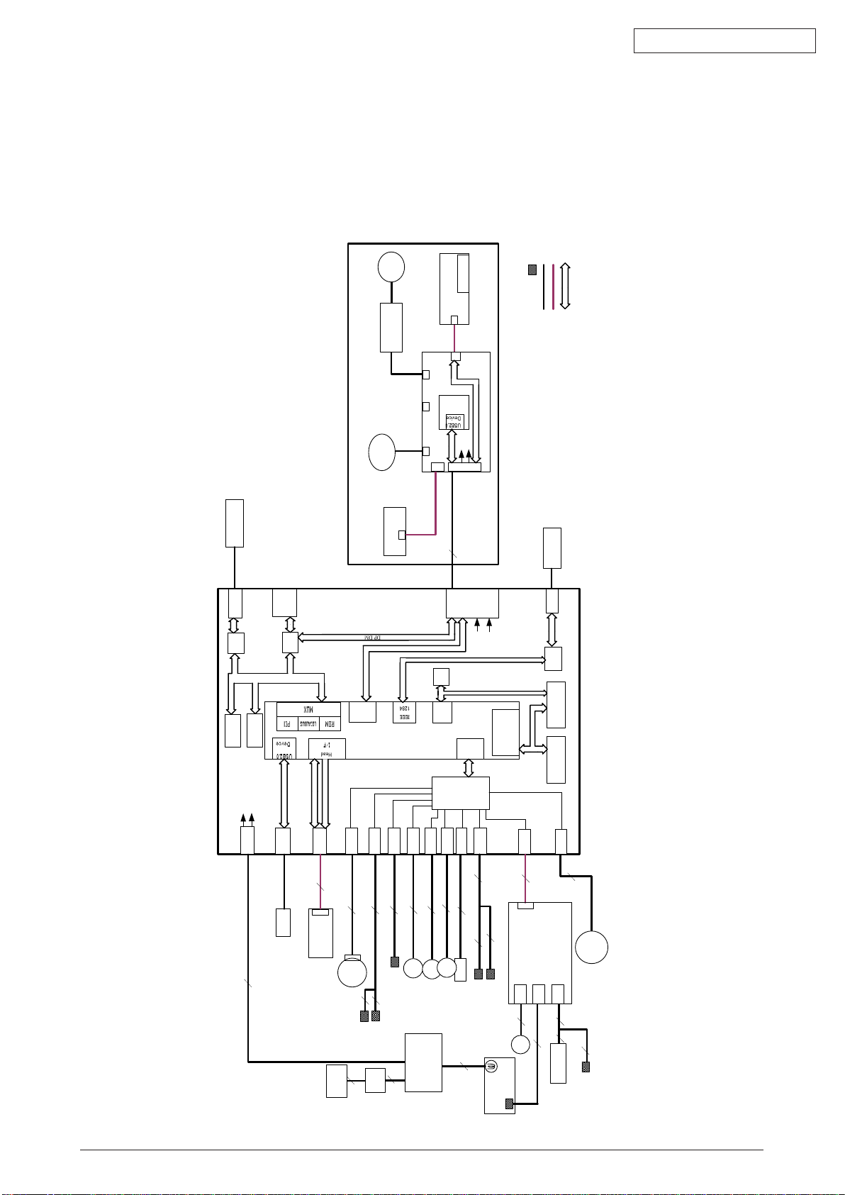
1. ConfiguRaTion
DM
PE
RCLT
THERM
HCLT
MCLT
SON
HVIF
EXRCO
Fax IF
PW
HEAD
PNLUSB
LAN
USB
CENT
DC Motor
Assy.
JST2
2
JST2
2
JST2
2
clutch
clutch
AMP8
8
USB IF
Centronics IF
JST24
24
JST24
Panel PCB
LCD
FB
Moter
CCD UNIT
20
JST20
JST20
Scanner Unit
JST9
9
28 JST28
FAN
2nd
Tray
6
JST7
Board-TT1
cover open switch
JST10
3
Cover open sensor
EXIT sensor
6
3
2
JST2
Temperature sensor
IP100
ALF
UPD7
202
AMP6
JST28
CN1
CN2
CN3
High Volt PCB
3
3
5
2
FUSER UNIT
2
2
AC Inlet
AC SW
2
2
86M
SPILYTAS 2
8051
I2C
16C550
UART
LC98500B
PU LSI
DDR
I/F
10
JST10
Nor
Nand
DIMM
I2C
ROM
64
Kbit
74LVC
161284
3
3
Paper end
duplex
JST9
SCANNER
PCB
L629
SOLENOID
ພ
ROM IF
PCI
ROM IF
PCI
2NDTRAY
LED HEAD UNIT
TXD/
RXD
DP/
DM
DP/DM
HEAD IF
HEAD Clock
RS232C
DP/
DM
RS232C
PUIF
DDR-
SDRAM
64
MB
I2C
DDR IF
IEEE1284
IEEE1284
Cable
FFC
Sensor
BUS
5V
24V
5V
24V
5V
24V
JST2
2
clutch
AFD
Moter
AFD PCB
LAN IF
Power Supply PCB
1.1 System Configuration
MB460
The system configuration of this product is shown in Figure 1-1-1.
Oki Data CONFIDENTIAL
44306601TH Rev. 2
Fig 1.1.1
7 /
Page 8
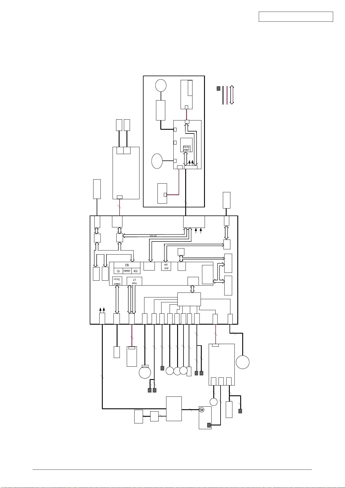
MB470/MB480
DM
PE
RCLT
THERM
HCLT
MCLT
SON
HVIF
EXRCO
Fax IF
PW
HEAD
PNLUSB
LAN
USB
CENT
DC Motor
Assy.
JST2
2
JST2
2
JST2
2
clutch
clutch
AMP8
8
USB IF
Centronics IF
JST24
24
JST24
FAX PCB
Panel PCB
LCD
FB
Moter
CCD UNIT
20
JST20
JST20
Scanner Unit
JST9
9
28 JST28
FAN
2nd
Tray
6
JST7
Board-TT1
cover open switch
JST12
JST10
3
Cover open sensor
EXIT sensor
6
3
2
JST2
Temperature sensor
IP100
ALF
UPD7
202
AMP6
JST28
CN1
CN2
CN3
High Volt PCB
3
3
5
2
FUSER UNIT
2
2
AC Inlet
AC SW
2
2
86M
SPILYTAS 2
8051
I2C
16C550
UART
LC98500B
PU LSI
DDR
I/F
10
JST10
Nor
Nand
JST12
12
DIMM
Line
Tel
I2C
ROM
64
Kbit
74LVC
161284
3
3
Paper end
duplex
JST9
SCANNER
PCB
L629
SOLENOID
ພ
ROM IF
PCI
ROM IF
PCI
2NDTRAY
LED HEAD UNIT
TXD/
RXD
DP/
DM
DP/DM
HEAD IF
HEAD Clock
RS232C
DP/
DM
RS232C
PUIF
DDR-
SDRAM
64
MB
I2C
DDR IF
IEEE1284
IEEE1284
Cable
FFC
Sensor
BUS
5V
24V
5V
24V
5V
24V
JST2
2
clutch
AFD
Moter
AFD PCB
LAN IF
Power Supply PCB
Line
Tel
The system configuration of this product is shown in Figure 1-1-2.
Oki Data CONFIDENTIAL
44306601TH Rev. 2
Fig 1.1.2
8 /
Page 9
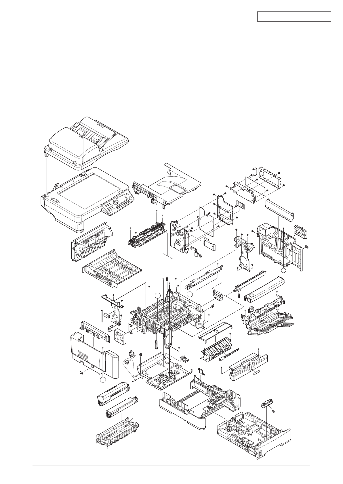
1.2 Structure of MFP
A
A
A’
A’
The insides of MB460/MB470/MB480 printers are composed of the following parts.
• Scanner part
• Electronic photography process part
• Paper path
• Control part (CU part/PU part)
• Power supply parts (high voltage part/low voltage part)
Figure 1-2 shows the composition of the MFP.
Oki Data CONFIDENTIAL
Fig 1.2.1
44306601TH Rev. 2
9 /
Page 10
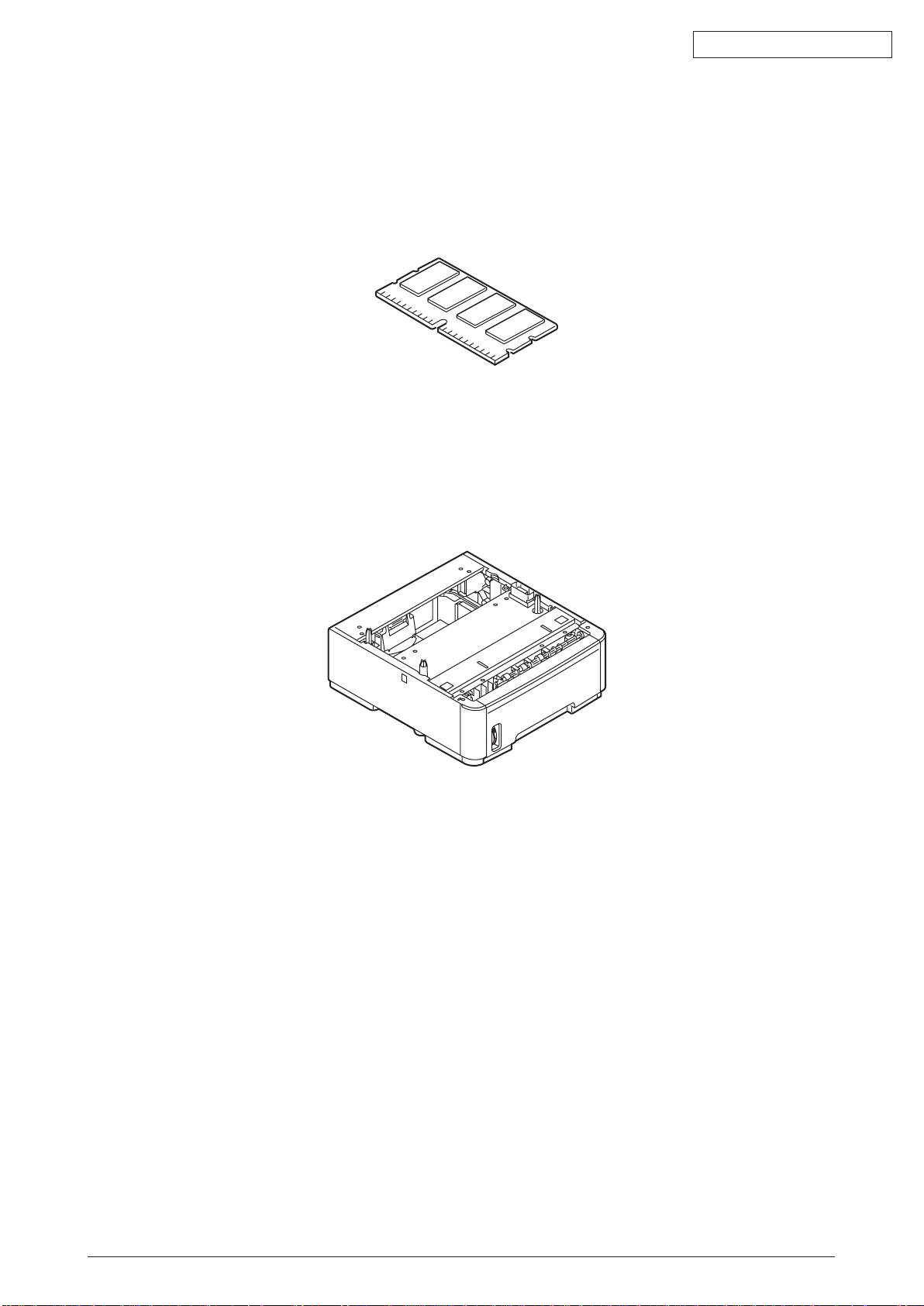
1.3 Offer of Options
This product can be installed with the following option.
(1) Additional memory board 64MB/256MB
Fig 1.3.1
Oki Data CONFIDENTIAL
(2) Option Tray
Fig 1.3.2
44306601TH Rev. 2
10 /
Page 11
Oki Data CONFIDENTIAL
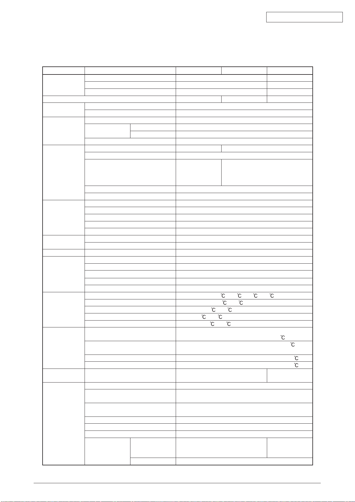
1.4 Specifications
Table 1.4.1
Category Item MB460 MB470 MB480
Exterior
Dimensions
Weight 17Kg 18.5Kg 19Kg
printer Engine Engine speed (A4/Letter) 28/30 PPM
Fast print time
(A4)
Resolution LED Head 600dpi 1200dpi
CPU Core PowerPC405
RAM Standard 64MB
ROM Program NOR-Flash 2MB + NAND-Flash 64MB
Power
Consumption
Operation
Environment
(temperature)
Operation
Environment
(humidity)
Duty Cycle Maximum 50,000 pages per month 70,000 pages per
Life Printer 180,000 pages or 5 years
Width 447mm 447mm
Depth 432mm 432mm
Height 500mm 529mm
Auto Duplex Standard
First Print Out Time Less than 5.5 seconds
Warm-up Time from Power On 60 seconds
from Power Save 25 seconds
Low noise mode Unavailable
Maximum input resolution F/B:1200 x 600dpi / ADF:1200 x 300dpi
Output resolution 600x600dpi
1200x600dpi
2400x600dpi(half
speed)
step 4 step 600 x 600dpi
Economic mode toner saving by lowering light
I-Cache 16KB
D-Cache 16KB
Clock 297MHz
Bus width 32bit
Option 64MB/256MB available (SO-DIMMx1)
Max. 800W
Normal Operation 500W
Stand-by 100W
Power Saver Mode 10W or less
Energy Star Application Yes
In operation 10
At stand-by 0 - 43 , power off
In storage (1 year max.) -10
At transport (1 month max.) -29
At transport (1 month max.) -29
In operation 20%-80%, 50%-70%
At stand-by 10%-90%, Max. wet bulb temperature : 26.8 with
In storage 10%-90%, Max. wet bulb temperature : 35
At transport 10%-90%, Max. wet bulb temperature : 40
Scanner Flatbed:50,000pages or 5years / ADF:240,000 pages
Duty cycle (M=L/12, A=L/12/5) 35,000 pages per month max.
MTBF (2.3% duty) 6,000 hours
MPBF 24,000 pages
MTTR 30 minutes
Toner
life@ISO19752
consumption 3,500
Starter 1500
- 50 , with drum and without toner
Max. wet bulb temperature : 25
5,000 pages per month average
- 32 , 17 - 27
- 43 , with drum and toner
- 50 , with drum and toner
7,000
1200x1200dpi
600x600dpi
power off
month
or 5years
3,500
7,000
12,000
44306601TH Rev. 2
11 /
Page 12
Oki Data CONFIDENTIAL
Category Item MB460 MB470 MB480
Life Image drum life
(w/o power save)
Operation noise Operating 56dB
Standby 32dB
Power save mode Back ground level
Paper handling Paper Input
Capacity
Paper Output
Capacity
Paper Size Legal/universal or A4 cassette/
Universal cassette
MP Tray 13,13.5,14Legal,Letter,Executive,A4,A5,B5,A6,C5,C6,DL
Duplex Letter,A4,up to Legal14"
Minimum paper
size
Paper Weight 1st Tray 16~32 lb. (60.16~120.32gsm)
Status switch/
Sensor
Communication
Interface
Emulation Standard PCL6/5e , SIDM PCL6/5e , SIDM , PS3
Option RAM RAM DIMM 1slot (64MB or 256MB)
Others USB-IF logo Available
1st Tray 3.94"x8.3" (210mm)
2nd Tray 5.8"x8.3"(210mm,A5)
MP Tray 3.4"x5.5"(140mm)
Duplex Auto Duplex Letter,A4;Manual Duplex 3.4"x5.5"
2nd Tray 16~32 lb. (60.16~120.32gsm)
MP Tray 16~43 lb. (60~160gsm) (Enve. : N/A)
Duplex Print 16~28 lb. (60.16~105.28gsm)
Paper tray empty Available
Paper low N/A
Toner Empty Available
Cover open Available
Fuser temp Available
Paper size N/A
Stacker full N/A
USB Host IF N/A
USB Device IF USB connector Type B (2.0 Hi-Speed)
Ethernet I/F RJ-45 (10/100 Base TX)
Tel/Line I/F N/A RJ-11x2 (PSTN/PBX , Ext-TEL)
Parallel I/F CEN36 (IEEE1284)
Wireless LAN N/A
Card Slots N/A
Option N/A
2nd tray 530 sheet tray
Emulation N/A
Windows logo Available
Operation by UPS Operation by UPS (outage free power supply) is not
Continuous 25,000 pages (at simplex)
3 pages per job 20,000 pages (at simplex)
1 page per job 12,000 pages (at simplex)
1st Tray Legal/universal cassette
250 sheets
2nd Tray (optional) Legal/universal cassette 530 sheets
MP Tray Single sheet
manual feed slot
Face up N/A
Face down 150 sheets
13,13.5,14Legal,Letter,Executive,A4,A5,B5
statement(first cassette only)
,Com-9,Com-10,Monarch,statement,Free
guaranteed. (Do not use UPS)
50 sheets Multi Purpose Tray
Free
Legal/universal
cassette
530 sheets
44306601TH Rev. 2
12 /
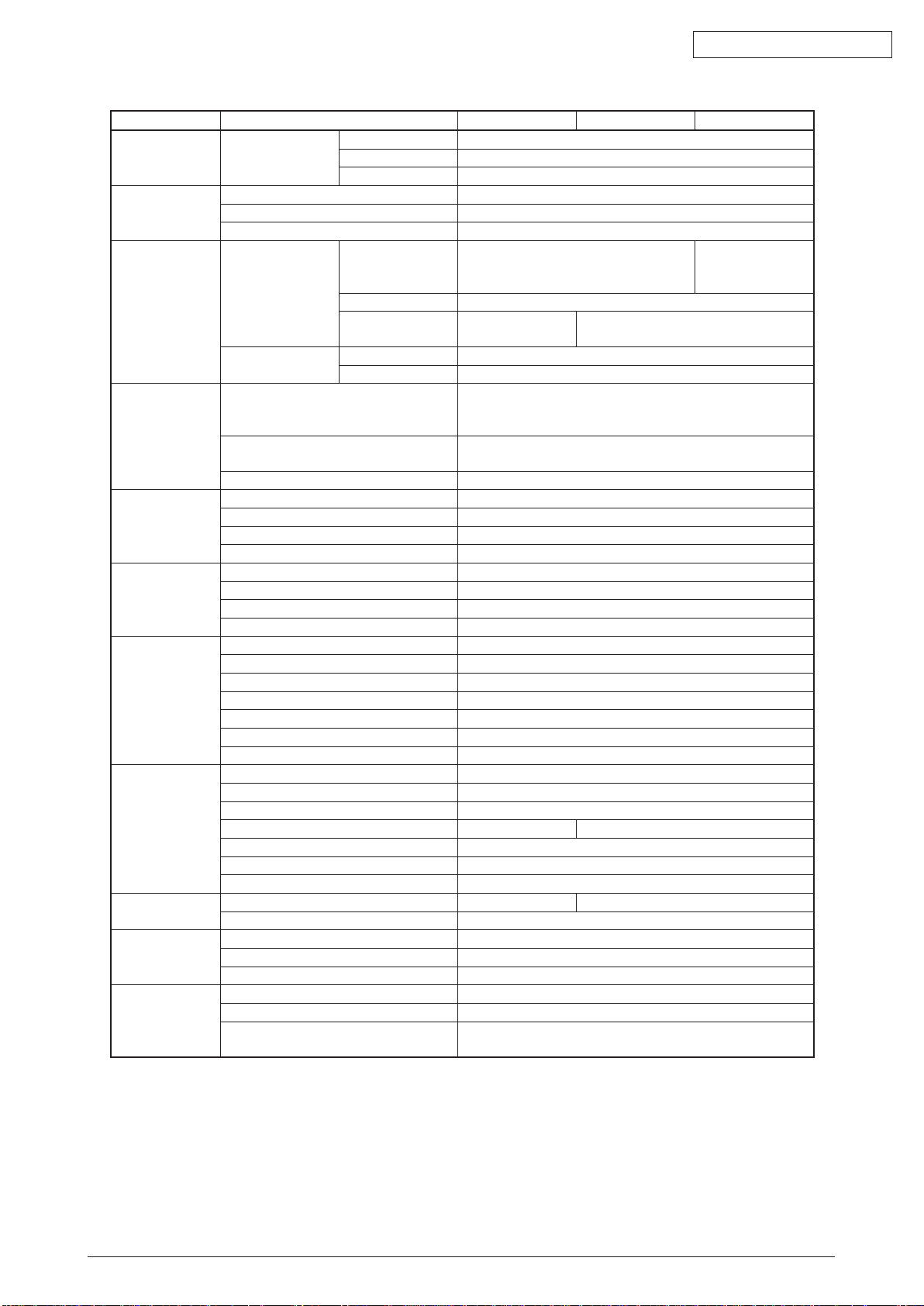
Page 13

2
3 4
1
1.5 Interface Specification
1.5.1 USB Interface Specification
1.5.1.1 Outline of USB Interface
(1) Basic Specification
USB
(2) Transmission Mode
Hi speed (480Mbps±0.05% max.)
(3) Power Control
Self power device
1.5.1.2 USB Interface Connector and Cable
(1) Connector
• Printer side: B receptacle
Upstream port
Equivalent of UBR24-4K5C00 (made by ACON)
Oki Data CONFIDENTIAL
Connector pin arrangement
Fig 1.5.1
• Cab
le side: B plug (off)
(2) Cable
Cable length: Specification Cable of USB2.0 spec. of less than 5m.(less than 2m is
recommended)
(
Shielded cable is used here.)
1.5.1.3 UBS Interface Signal
Table 1.5.1
Name of Single Function
1 Vbus Power Supply (+5V)(red)
2 D - Data transmission (white)
3 D + Data transmission (green)
4 GND Single ground (black)
Shell Shield
44306601TH Rev. 2
13 /
Page 14
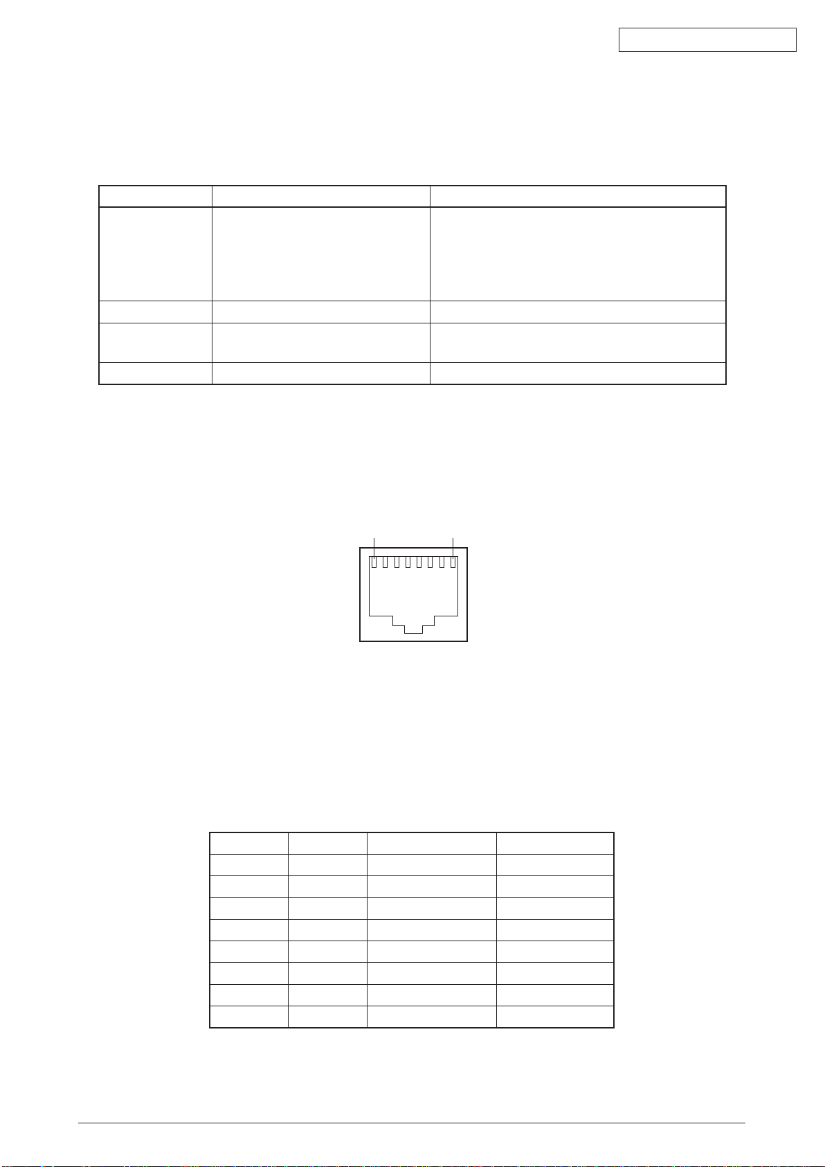
1 8
1.5.2 Network Interface Specification
1.5.2.1 Outline of Network Interface
Table 1.5.2 Basic Specification of Network Interface
Protocol Family Network Protocol Application
TCP/IP ARP,IP,ICMP,IPv6,TCP,UDP LPR,Port9100,FTP,HTTP,HTTPS,IPP,
SNMPv1/v3,TELNET,DHCP/BOOTP,DNS,
DDNS,WINS,UPnP,Bonjour,SNTP,SMTP,
POP3,Windows Rally(WSD Print,LLTD),
ODNSP,SSL/TLS,LDAP,Kerberos
NBT/NetBEUI SMB,NetBIOS,NetBIOS over TCP
EtherTalk ELAP,AARP,DDP,AEP,NBP,ZIP,R
TMP,ATP,PAP
IEEE802.1X EAP-TLS,PEAP
Oki Data CONFIDENTIAL
1.5.2.2 Network Interface Connector and Cable
(1) Connector
100 BASE-TX/10 BASE-T (automatic switch, no simultaneous use)
Connector pin arrangement
Fig 1.5.2
(2)
Cable
Unshielded twist pair cable with RJ-45 connector (Category 5 is recommended.)
1.5.2.3 Network Interface Signal
Table 1.5.3
Pin No. Singles Single Direction Functions
1 TXD+ FROM PRINTER Send Data +
2 TXD- FROM PRINTER Send Data 3 RXD+ TO PRINTER Received Data +
4 - - Unassigned
5 - - Unassigned
6 RXD- TO PRINTER Received Data 7 - - Unassigned
8 - - Unassigned
44306601TH Rev. 2
14 /
Page 15
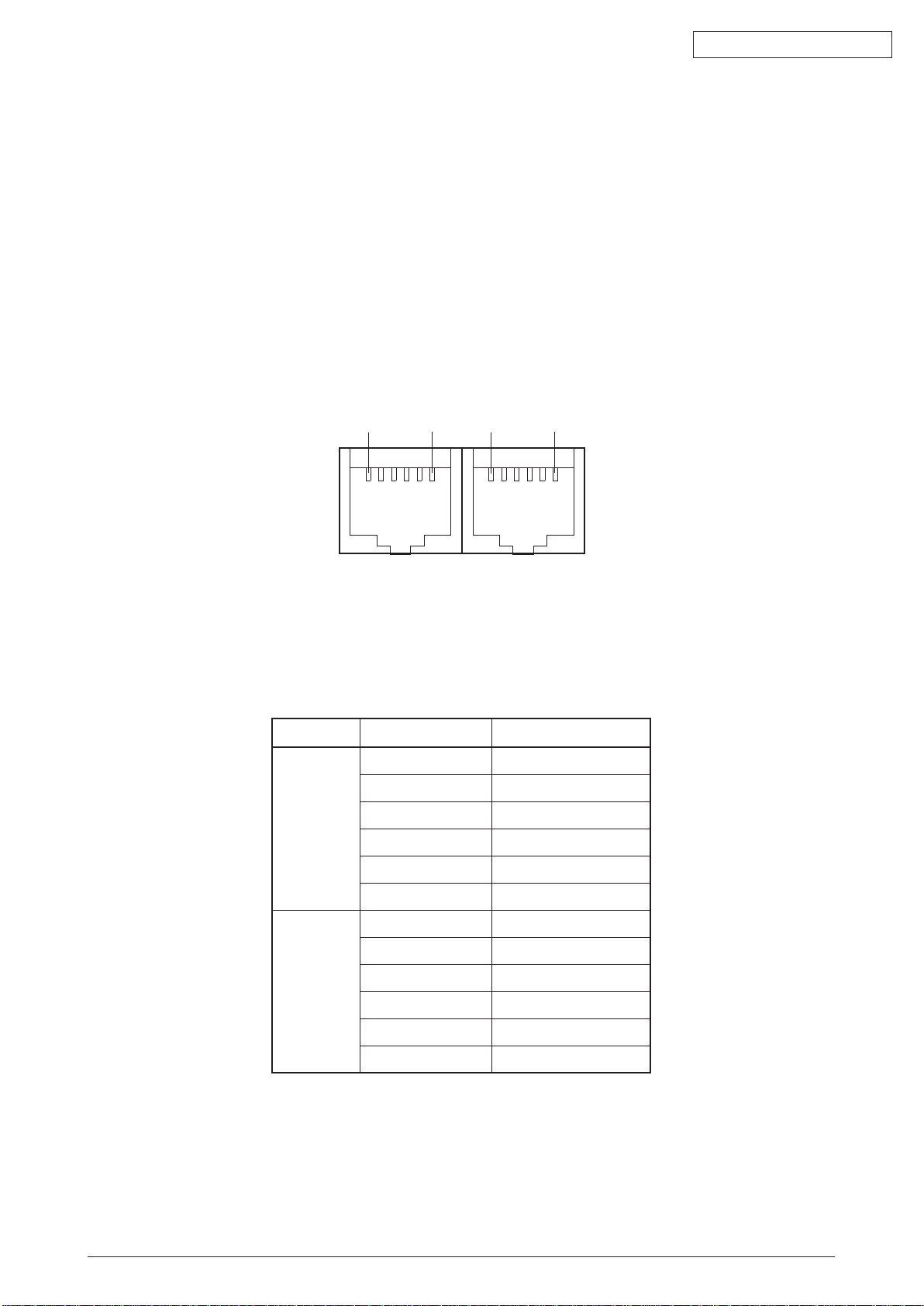
1.5.3 Telephone Line Interface Specification (Only MB470/MB480)
A1 A6
B1 B6
TEL
LINE
1.5.3.1 Outline of telephone Line Interface
The machine will reliably communicate with distant stations over voice-level telephone line.
1.5.3.2 Telephone Line Interface Connector and Cable
Printer side : RJ-11
Cable side : TEL Cable (Cable with plug)
Connector contact arrengement
Oki Data CONFIDENTIAL
1.5.3.3 Telephone Line Interface signal
Contact No. Functions
TEL A1 Unspecified
A2 Unspecified
A3 TCP
A4 TCP
A5 Unspecified
A6 Unspecified
LINE B1 Unspecified
B2 Unspecified
B3 TCP
B4 TCP
B5 Unspecified
Fig 1.5.3
Tabel 1.5.4
TCP : Terminal Connection Point
44306601TH Rev. 2
B6 Unspecified
15 /
Page 16
1.5.4 Parallel Interface Specifications
118
1936
1.5.4.1 Parallel Interface Overview
Table 1.5.5
Item Details
Corresponding mode Comatible mode, nibble mode, ECP mode
Data bit length Compatible: 8, Nibble: 4, ECP: 9 bit
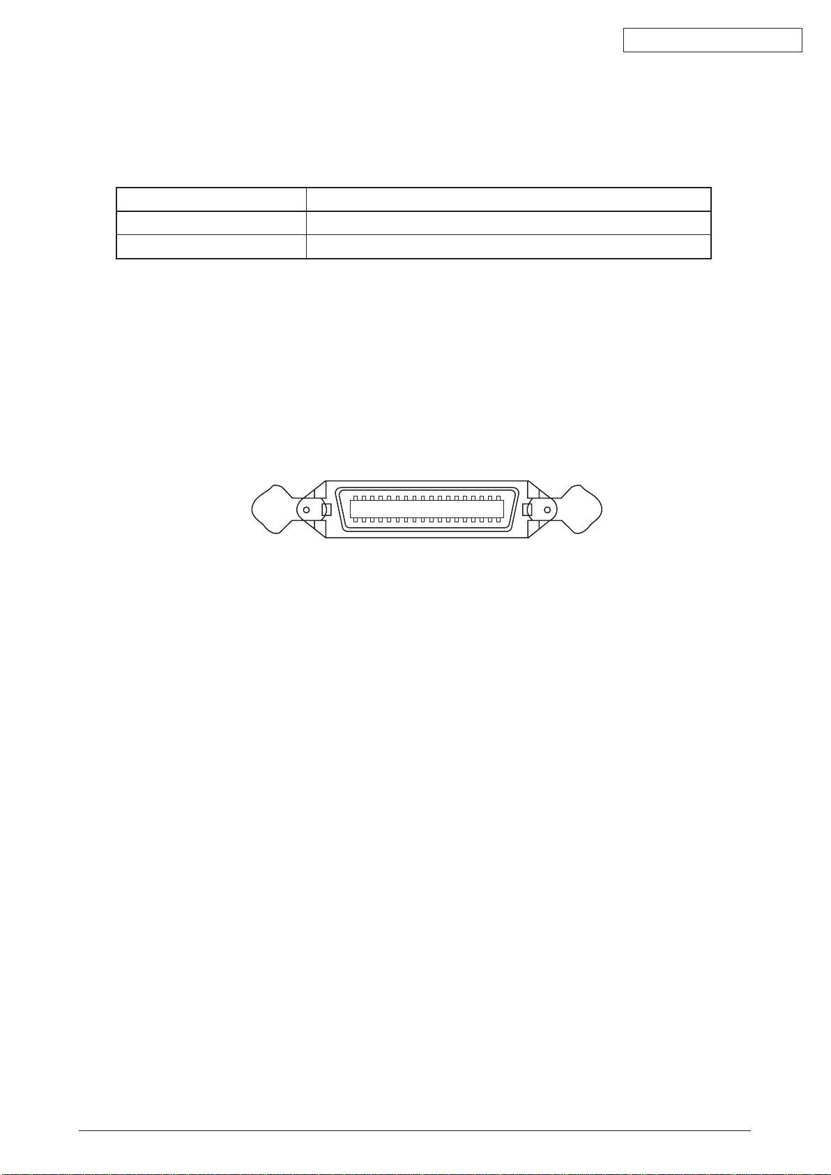
1.5.4.2 Parallel Interface Connector and Cable
(1) Connector
Printer: 36pConnector (Female)
57LE-40360-12 (D56) (DDK Ltd.) equivalent product
Cable: 36pConnector (Male)
57FE-30360-20N (D8) (DDK Ltd.) equivalent product
Oki Data CONFIDENTIAL
Pin arrangement from interface cable side
Fig 1.5.4
Cable
(2)
Use a cable shorter than 1.8m.
(Use a cable with a shielded twisted-pair wire for to prevent noise interference.)
1.5.4.3 Parallel Interface Level
Low Level : 0.0V to +0.8V
High Level : +2.4V to +5.0V
44306601TH Rev. 2
16 /
Page 17

2. oPeRaTional exPlanaTion
2.1 Electrophotographic process mechanism
(1) Electrophotographic process
The following describes the overview of electrophotographic process.
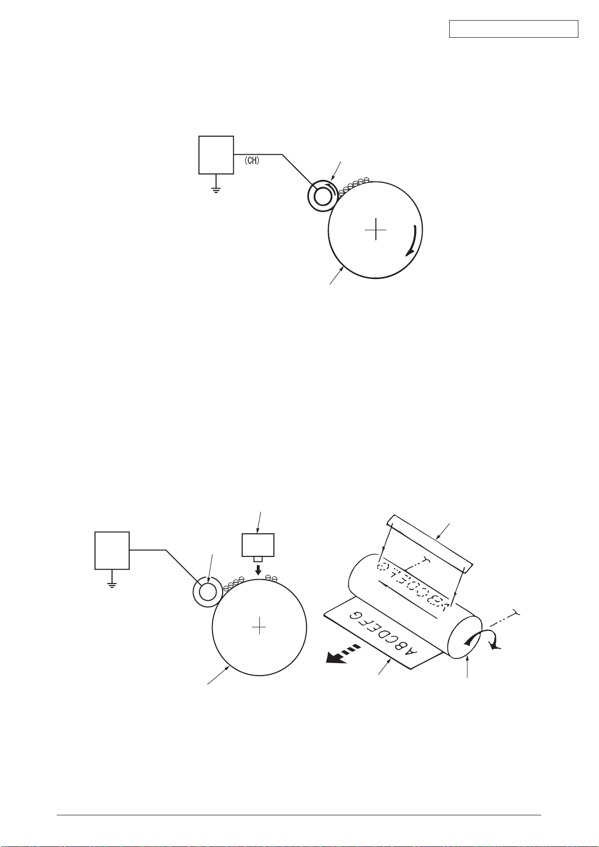
1. Charging
Equally charge the surface of image drum by implying negative voltage to the
charged roller due to negative charge.
2. Exposure
The light from LED Head is exposed on the negative-charged surface of image drum.
The surface electrical potential of the exposed part of image drum surface becomes
lower. Then forms electrostatic latent image.
3. Development
Negative-charged toner is attracted to the electrostatic latent image due to
electrostatic while touching the image drum. Then forms viewable image.
4. Transfer
Overlap paper on the surface of OPC drum, from the backside of paper transfer
toner image to the paper by applying electrical charge by transfer roller.
5. Drum cleaning
The remaining toner on the image drum that is not transferred is made to be
equable by cleaning roller. And is temporarily attracted to the cleaning roller due to
electrostatic.
6. Fusing
The toner image that is transferred to paper is fused on paper by heat and pressure.
Oki Data CONFIDENTIAL
44306601TH Rev. 2
17 /
Page 18
Oki Data CONFIDENTIAL
Image drum
Charged roller
Power
Charged roller
LED head
LED head
Image drum
Image drum
Paper
Power
1. Charging
Charge the image drum surface by implying voltage to the charged roller that contacts the image
drum surface.
Fig 2.1.1
2. Exposure
The light emitting from the LED Head will be exposed to the negative charged image drum. When
the surface electric potential of exposed part of the image drum goes to decrease, the electrostatic
latent image complying with image signal is formed.
Image drum is coated by basic layer (UL), charge generating layer (CGL), charge transferring layer
(CTL) on the basic material aluminum. The thickness of the organic light sensor (OPC) that is
consisted by CTL and CGL is approximate 20µm.
44306601TH Rev. 2
Fig 2.1.2
18 /
Page 19
Oki Data CONFIDENTIAL
Image drum
Charged roller
Image developing plate
Toner supply roller
Image
developing
roller
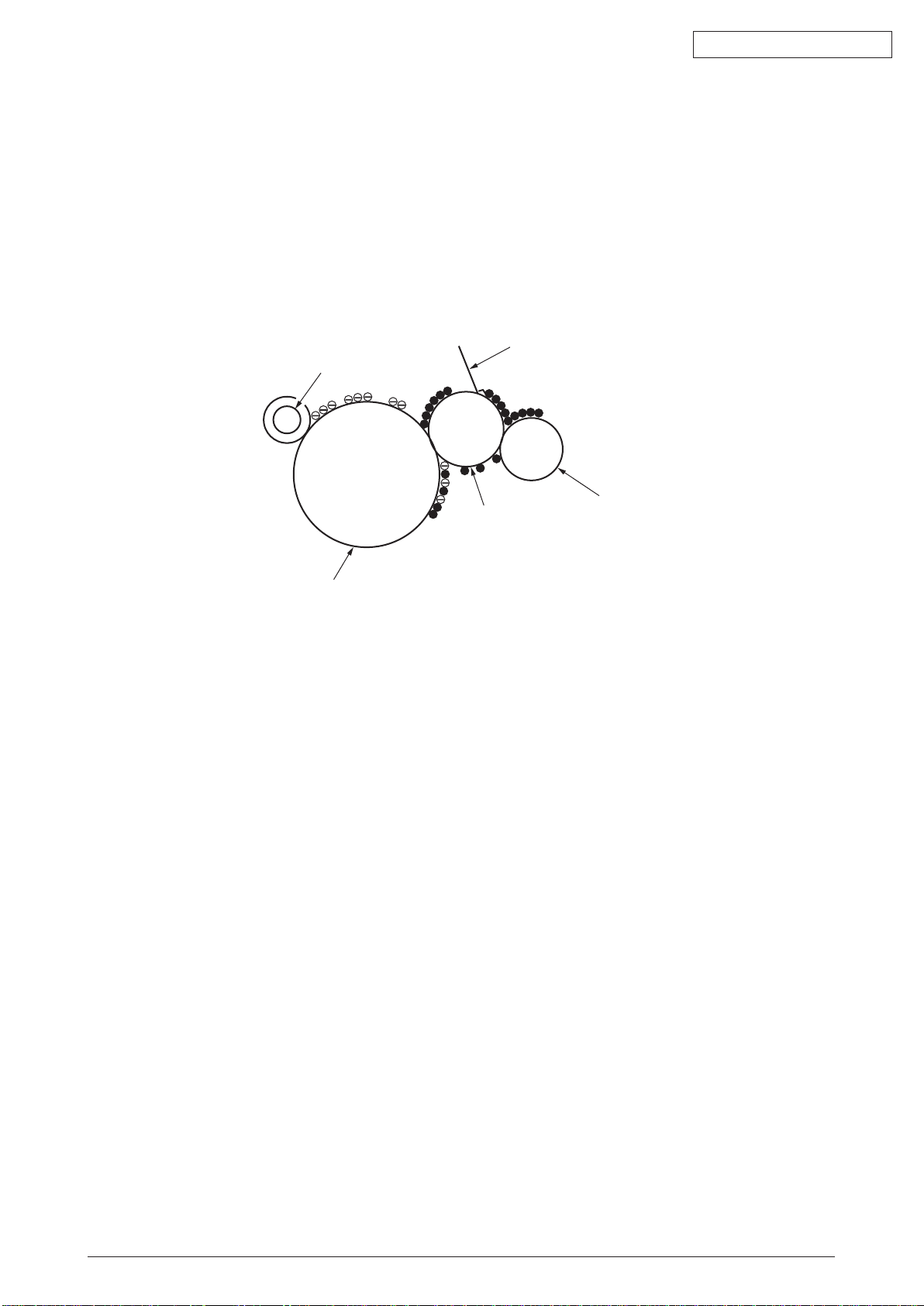
3. Image development
Toner is attracted to the electrostatic latent image on the image drum surface, then the electrostatic
latent image changes to toner image.
1 As
the roller on the supply spot of toner rotates while scrubbing the image-developing
roller, fiction electricity occurs between the image developing roller and toner; toner is
attracted to the image-developing roller.
e toner that has been attracted to the image-developing roller is dropped down to
2. Th
the developing plate to make a thin toner film on the image developing roller side.
Fig 2.1.3
3 The toner is attracted by the exposed part (Low electrical potential part) of the image
drum when the image drum contact the image developing roller, so as to see the
electrostatic latent image.
44306601TH Rev. 2
19 /
Page 20
Oki Data CONFIDENTIAL
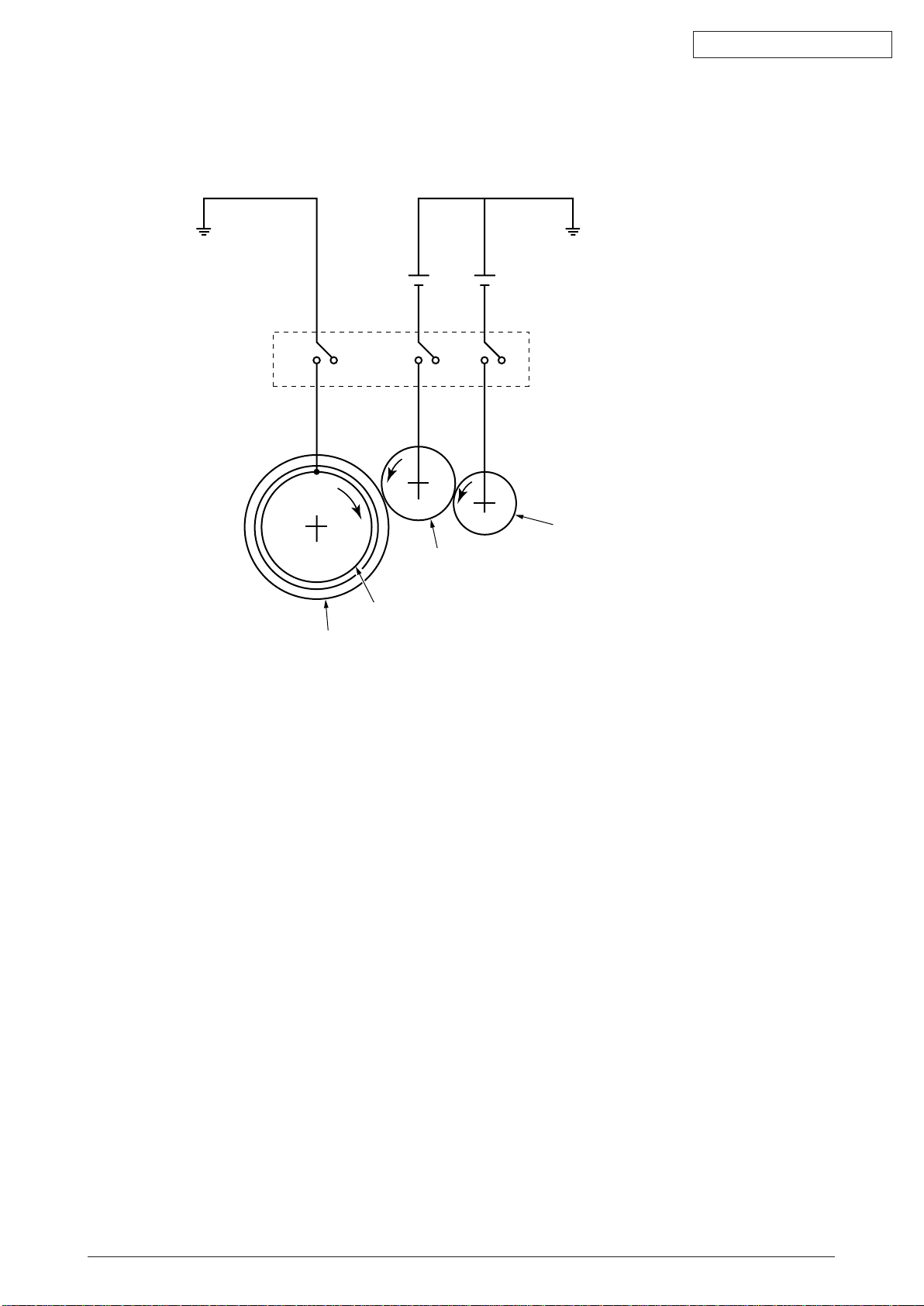
Image drum
Basic material
Toner feeding roller
While the cover is closed it will be
connected and bias will be applied.
Image developing roller
Note! The necessary bypass voltage in image processing is impressed on the toner feeding
roller and image developing roller as show below.
Fig 2.1.4
44306601TH Rev. 2
20 /
Page 21
Oki Data CONFIDENTIAL
Image drum
Transfer roller
Paper
Power
4. Transfer
The transfer roller, which is from conductive sponge material, is created to meet intimate
attachment of image drum roller surface and feeding paper. The feeding paper is set up on the
surface of image drum. Plus charge, which is the converse polarity with toner polarity, is applied
from the backside of the paper.
As high plus voltage is applied to transfer roller from the power supply, the plus charge on the
transfer roller surface is induced and transferred to the paper while the paper contact the transfer
roller. The negative charged toner, which has been attracted to the image drum surface, is
transferred to the surface of feeding paper by the plus charge of the backside of the paper.
Fig 2.1.5
44306601TH Rev. 2
21 /
Page 22

Oki Data CONFIDENTIAL
Power supply
Cleaning roller
Image drum
Transferring roller
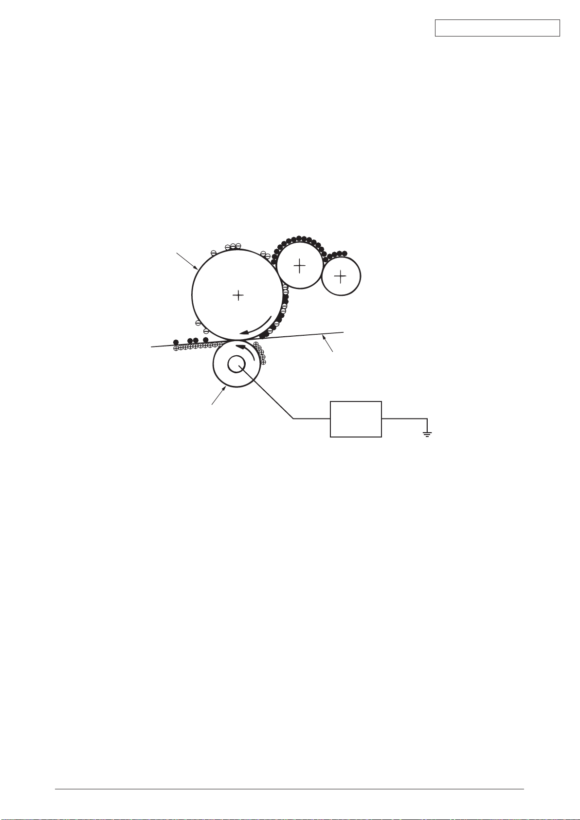
5. Drum cleaning
1 Cleaning
After the completion of transferring, the remaining toner on the image drum is temporarily
attracted by the electrostatic and the image drum surface is cleaned.
Fig 2.1.6
2 Roller cleaning
In the following case, there is a need of cleaning the charged roller, transfer roller, and
cleaning roller.
•
Warming up as switching on the power supply
•
Warming up after open-close of the cover
•
In case of termination of printing operation
•
By periodically change the bias voltage that is implied to each roller during continuous
printing, transfer the attached toner from roller to image drum and then return it to
developing device.
44306601TH Rev. 2
22 /
Page 23
Oki Data CONFIDENTIAL
Separating clutch
Feeding paper
Heater
Heat roller
Thermistor
Backup roller
Pressuring spring
Thermostat
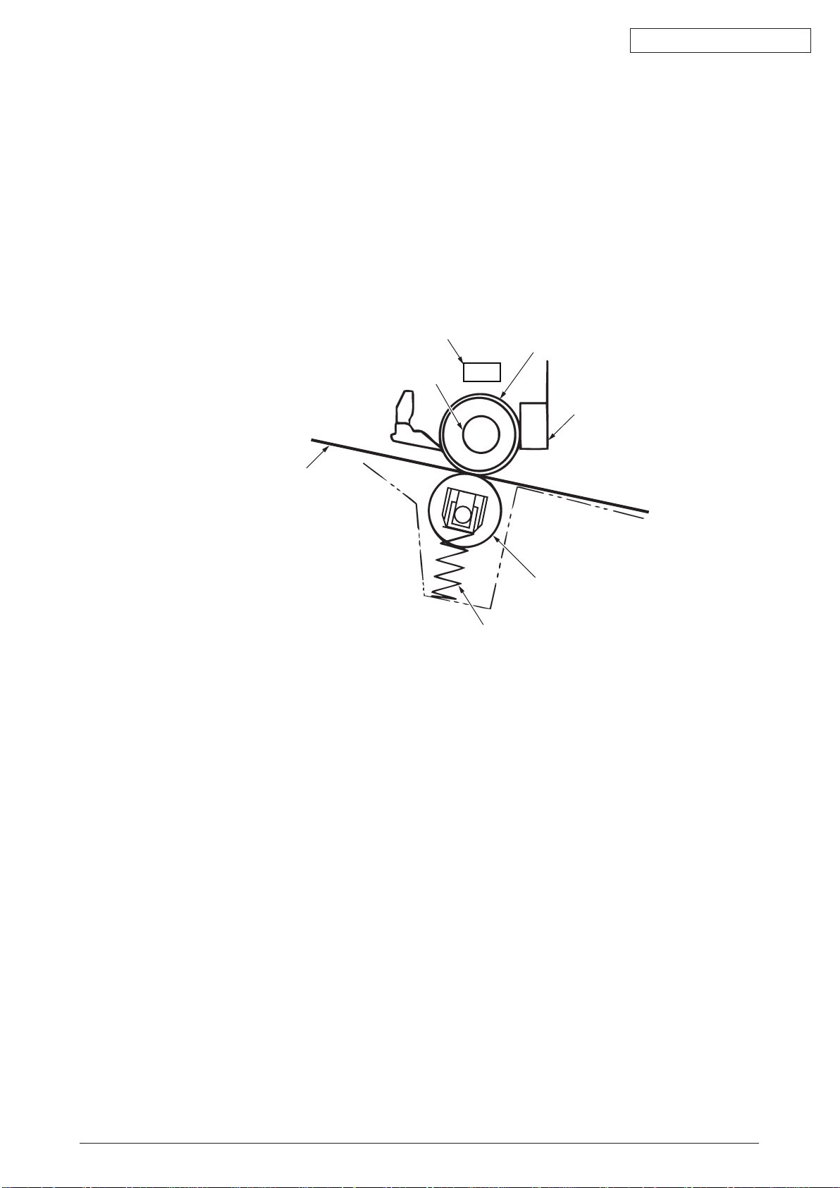
6. Fusing
After the termination of transfer the unsettled toner image is settled to paper by heat and pressure
while passing between Heat roller and Back up roller. Heat roller is Teflon coated and is mounted
by heater that can generate heat (Halogen lamp).
The thermistor that contacts the Heat roller adjusts the Heat roller temperature to the temperature
specified by the menu complying with the paper width. For safety the thermostat shuts off the
voltage supply to the Heater by opening the thermostat in the case of abnormally temperature
increasing.
The back up roller is held by the pressure springs on each terminal due to the pressure applied.
Fig 2.1.7
44306601TH Rev. 2
23 /
Page 24
Oki Data CONFIDENTIAL
:
:
:
:
:
:
:
:
:
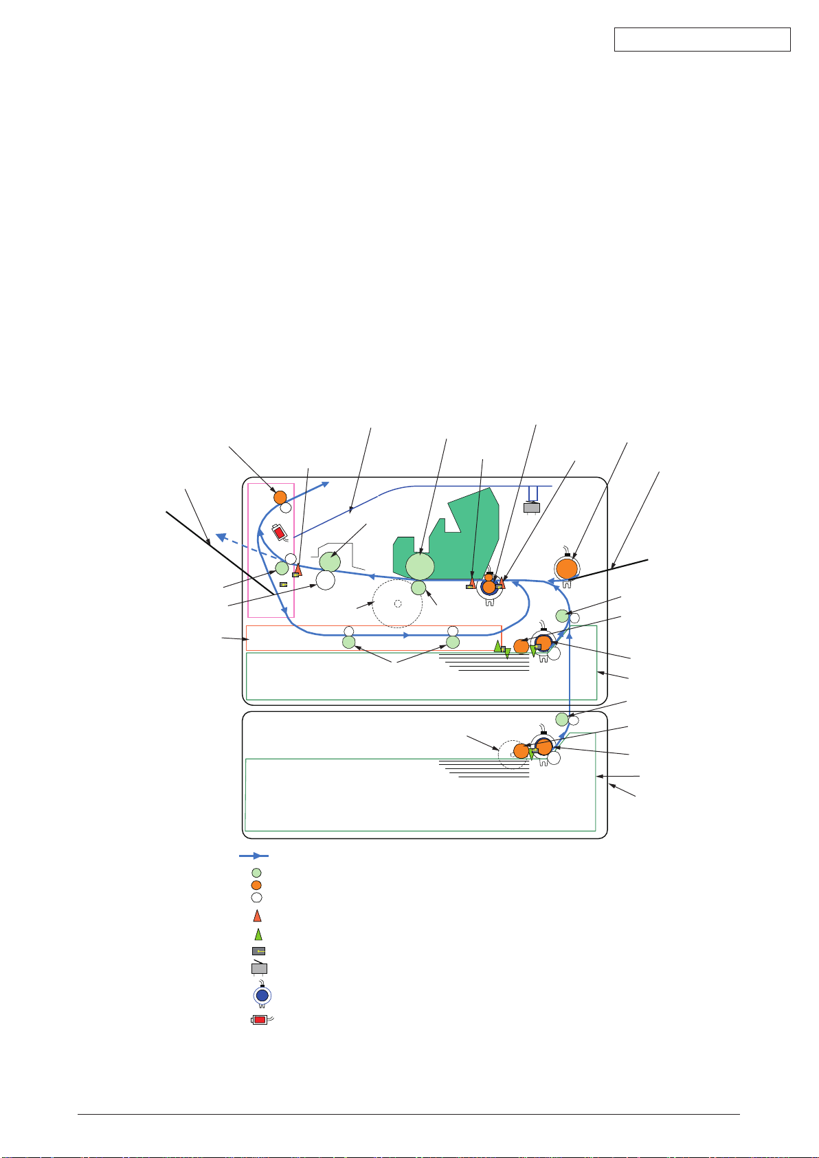
Face down stacker
Face up stacker
The 2nd ejecting roller
The 1st ejecting roller
Backup roller
Duplex unit
Ejecting
sensor lever
Resist roller
MPT feeding roller
Multipurpose tray
Conveying roller
Conveying roller
Transferring roller
Pulse motor
Paper conveying route
Driving roller (Continuous rotation)
Driving roller (Control rotation)
Driving roller
Paper level indicator lever
Indicating lever
Photo sensor
Micro switch
Magnetic clutch
Solenoid
DC motor
Heat roller
Conveying roller
Pick up roller
Pick up roller
Feeding roller
Feeding roller
Tray 1
Tray 2
2nd tray unit (option)
Entrance
sensor lever
Image drum
Writing out
sensor lever
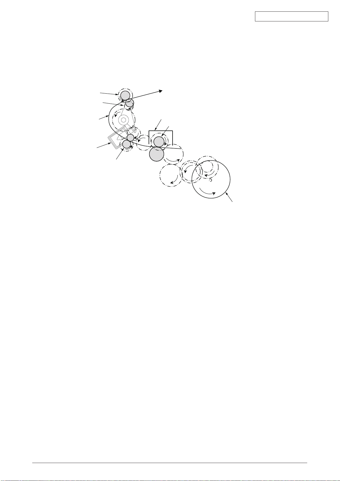
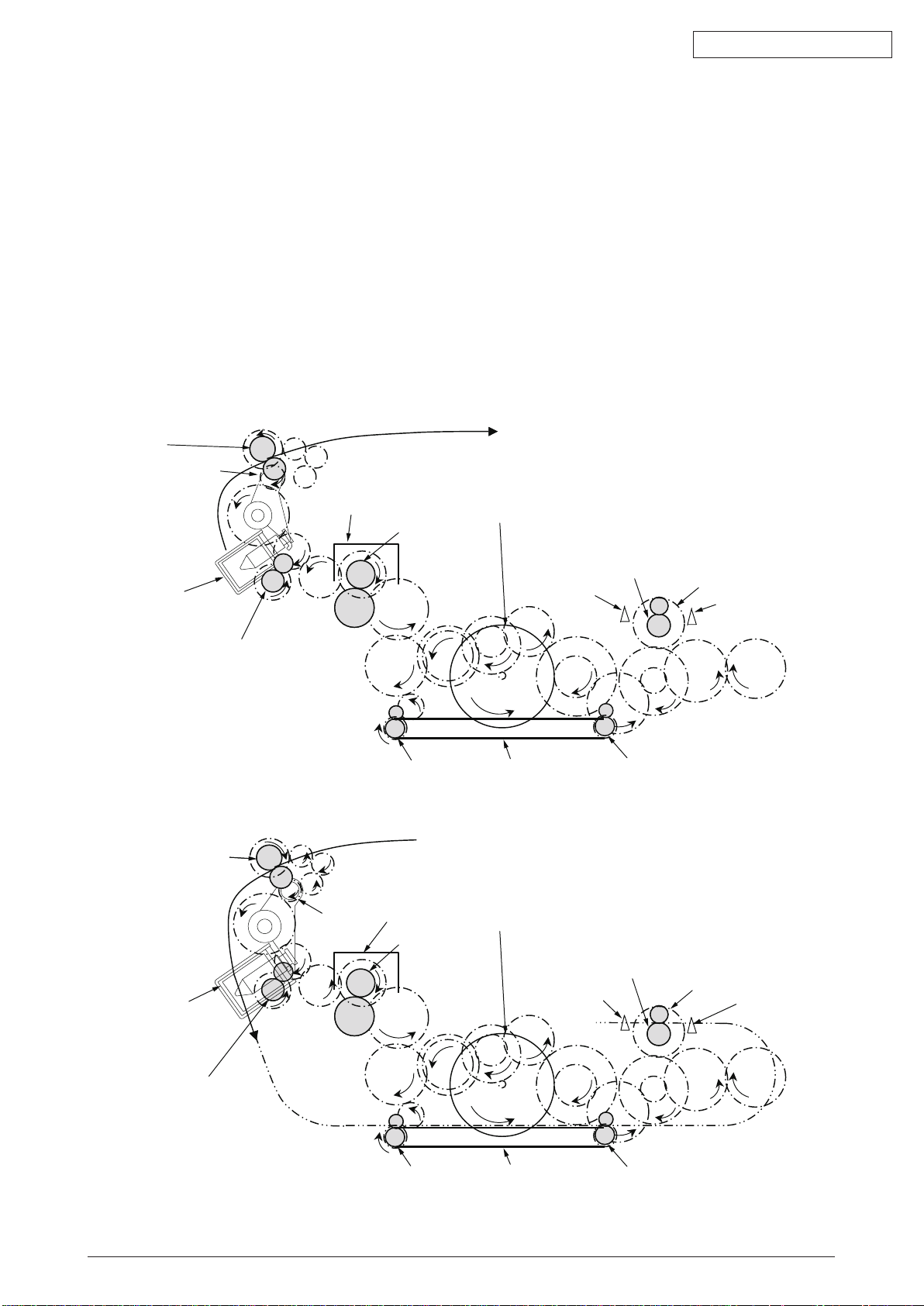
2.2 Printing process
The paper fed from Tray 1 and Tray 2 is conveyed by feeding roller, conveying roller, and resist
roller. When feeding paper is from MPT, it is conveyed by MPT, feeding roller, and resist roller.
After that the feeding paper that is conveyed by image drum and the nip part of transfer roller
forms toner image on the paper through electrophotographic process. And then, the toner on the
paper is fused by the heat and pressure as the fuser unit passing through. The paper that fused
the toner image is ejected from the face down stacker of the ejecting roller. In the case of face
up ejecting, it needs to open the backside cover and install face up stacker. (It is unavailable for
duplex printing while it is face up ejecting.)
The above is about the operations at simplex printing, yet the below explains the operations at
duplex printing. While duplex printing, the paper, which firstly passed through the fuser unit after
the backside printing, is conveyed to the inward of Duplex Unit, by the reverse operation of the
second ejecting roller that is a certain time after removing the first ejecting roller of the paper rear
side. Paper, is conveyed by conveying roller of Duplex Unit, and then merges to the same route
with the feeding paper that is from the tray. Onwards, it is the same with the simplex printing
operation by the feeding paper from tray.
44306601TH Rev. 2
Fig 2.2.1
24 /
Page 25
Oki Data CONFIDENTIAL
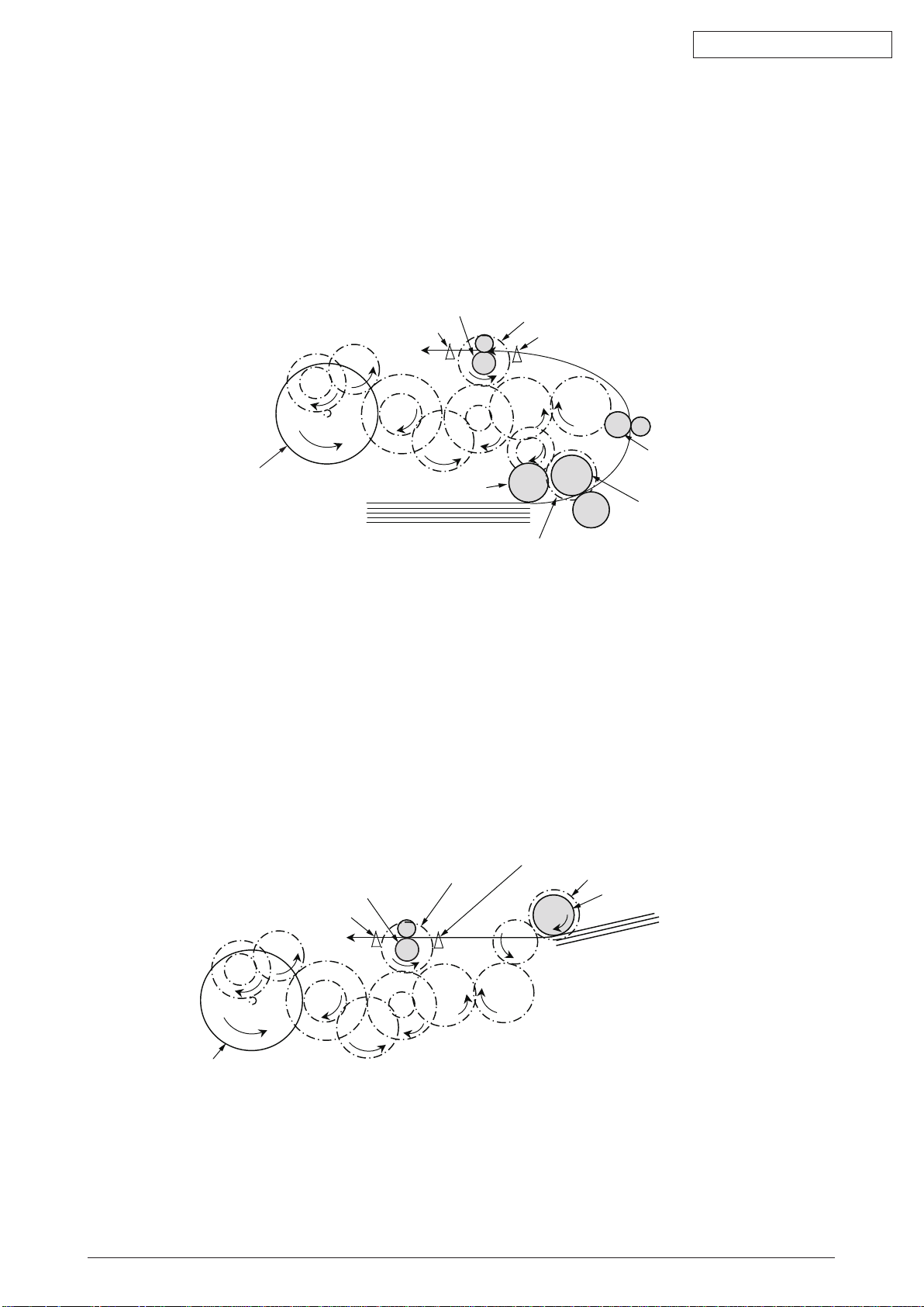
Resist roller
Resist clutch
Entrance sensor lever
Conveying roller
Paper feeding roller
Pick up roller
DC motor
(Counterclockwise rotation)
Paper feeding clutch
Paper
Writing out sensor lever
Resist clutch
Writing out sensor lever
Resist roller
Entrance sensor lever
Paper feeding clutch
MPT paper feeding roller
Paper
DV motor
(Counterclockwise rotation)
(1) Paper feeding from Tray 1
1. As DC motor rotating (Counterclockwise rotation), if set the paper feeding clutch as ON,
as the paper feeding roller and pick up roller rotating, the paper that is inside the tray is
conveyed.
2. T
he paper is conveyed by the conveying roller. After the entrance sensor level set to be ON,
it bumps into the stopping resist roller, a certain more amount of paper is conveyed. (This
corrects the paper skew.)
f set the resist clutch as ON, the paper is conveyed by resist roller.
3. I
Fig 2.2.2
(2) Paper feeding from Multipurpose tray (MPT)(MB470,MB480)
1. As DC motor rotating (Counterclockwise rotation), if set paper feeding clutch as ON the MPT
paper feeding roller starts to rotate, the paper in the tray is conveyed.
fter setting the entrance sensor lever as ON, the paper bumps into the stopping resist roller, a
2. A
certain more amount of paper is conveyed. (This corrects the skew of paper.)
f set the resist clutch as ON, the paper is conveyed by resist roller.
3. I
44306601TH Rev. 2
Fig 2.2.3
25 /
Page 26
(3) Fuser unit and paper ejecting
Eject roller
Eject roller
Planet gear
Paper route
Solenoid
Fuser unit
Heat roller
DC motor
(Counterclockwise rotation)
1. The fuser unit and eject roller is
2. Si
multaneously the eject roller rotates, and then the paper is ejected.
Oki Data CONFIDENTIAL
Fig 2.2.4
44306601TH Rev. 2
26 /
Page 27
Oki Data CONFIDENTIAL
Fuser unit
Fuser unit
Heat roller
Heat roller
DC motor
(Counterclockwise rotation)
DC motor
(Counterclockwise rotation)
Resist roller
Resist roller
Resist clutch
Resist clutch
Resist Entrance
sensor lever
Resist Entrance
sensor lever
Duplex conveying roller
Writing out
sensor lever
Writing out
sensor lever
Duplex conveying roller
The 1st ejecting roller
The 1st ejecting roller
The 2nd ejecting
roller
The 2nd ejecting
roller
Planet gear
Planet gear
Solenoid
(OFF)
Solenoid
(ON)
[ Normal rotation ]
[ Inverse rotation ]
Belt
Duplex conveying rollerDuplex conveying roller
Belt
(4) Paper reversing and paper multi-feeding
1. TRemoving the first eject roller at the rear part of paper and set the solenoid as ON for a
while, then the planet gear starts to move, the second eject roller starts inverse rotating
(Counterclockwise rotation).
2. B
y the inverse rotation of the second eject roller the paper is inversely rotated and conveyed to
Duplex.
aper is conveyed by Duplex conveying roller.
3. P
fter setting the entrance sensor lever as ON, paper bumps into the stopped resist roller, still a
4. A
certain more amount of paper is conveyed. (This corrects the skew of paper.).
f set the Resist clutch as ON, paper is conveyed by Resist roller.
5. I
Fig 2.2.5
44306601TH Rev. 2
Fig 2.2.6
27 /
Page 28
Oki Data CONFIDENTIAL
Magnet
Agitating bar Agitating gear
Crack part
Agitating bar
Agitating bar
Agitating gear
Sensor plate
Sensor plate
Toner sensor
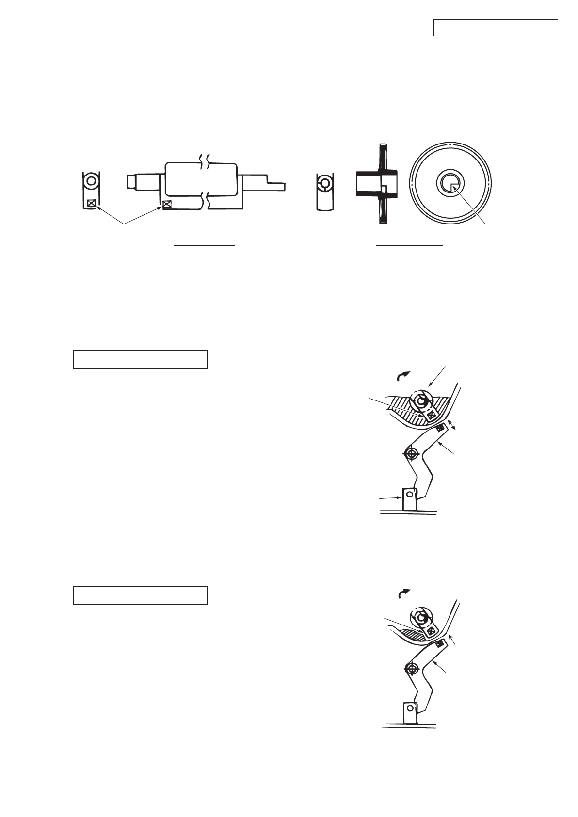
2.3 Toner entrance detection
• Equipment
Toner entrance detecting equipment consists the agitating gear that agitating the agitating bar at
a certain speed and magnet that is on the agitating bar.
Fig 2.3.1
•
Operation
Detecting the toner low by monitoring the congruous time intervals between the magnet that is
set on the sensor plate and the magnet attached on the agitating bar,
Operation in toner full status
•
The crack part of agitating gear meshing with
the projection portion of agitating bar, the
agitating bar rotates in accordance with the
rotating of gear.
•
Even after the magnet part of the agitating
Bar reaches the highest position, it still
rotates at the same speed by the pressure of
the agitating gear due to the toner resistance.
Fig 2.3.2
Operation in toner low status
•
When the magnet part of the agitating bar
reaches the highest position, because
there is no resistance from toner, the
agitating bar drops earlier than the gear
by the gravity itself, and stops by that
status.
For this reason, the time that the magnet
of agitating Bar magnetic attracts the
magnet of sensor plate becomes longer.
The toner low status can be inspected by
Fig 2.3.3
monitoring this time.
44306601TH Rev. 2
28 /
Page 29
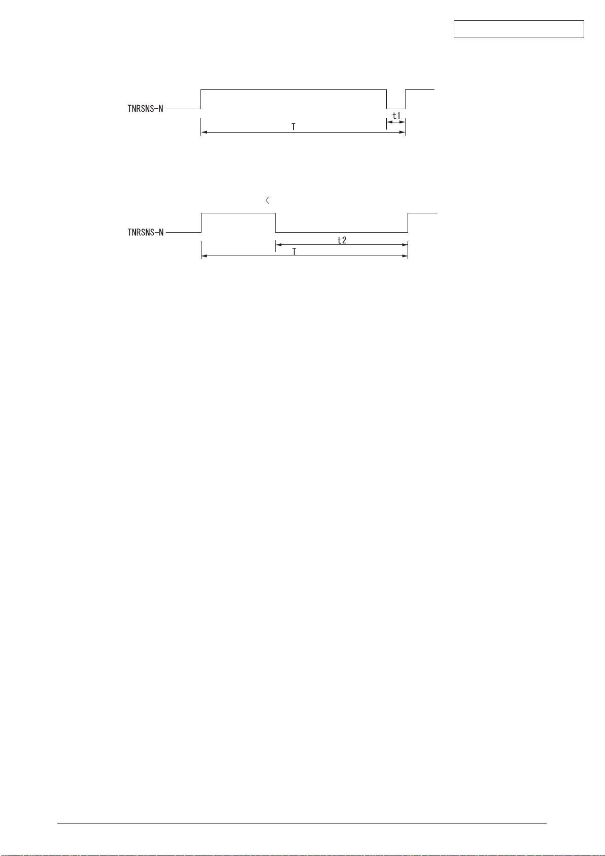
Toner full status
Oki Data CONFIDENTIAL
Fig 2.3.4
Toner low status t1
ner sensor alarm actuates if there is not any change on toner sensor.
• To
• Toner sensor is not monitored while main (drum) motor is stopping.
t2 t1,t2: Magnet attracting time
Fig 2.3.5
44306601TH Rev. 2
29 /
Page 30

Oki Data CONFIDENTIAL
3. MfP insTallaTion
3.1 Precautions and Prohibition
Table 3.1.1
• Do not install the MFP in the vicinity of high temperature or fire.
• Do not install the MFP at the place where a chemical reaction may take place (laboratory,
etc.).
• Do not install the MFP near flammable solution like alcohol, thinner, etc.
• Do not install the MFP at the place where a small child can reach.
• Do not install the MFP at an unstable place (unsteady frame, tilted place, etc.).
• Do not install the MFP at a highly humid or dusty place or under the direct sunshine.
• Do not install the MFP under the environment of sea breeze or caustic gas.
• Do not install the MFP at a highly vibrating place.
• When you drop the MFP or damage the cover, remove the power plug from the outlet and
contact the Customers’ Service Center.
Electric shock, fire or injury may occur.
• Do not connect the power cord, printer cable and earth wire as otherwise directed by the
Manual. A fire may break out.
• Do not insert a thing in the vent hole.
Electric shock, fire or injury may occur.
• Do not place a cup with water on the MFP.
Electric shock or fire may occur.
• Do not touch the fuser unit when you open the printer cover.
Burn may occur.
• Do not throw the toner cartridge or image drum cartridge into fire.
Burn may occur by the dust explosion.
• Do not use a highly flammable spray near the MFP.
Fire may break out as there are high temperature parts inside the printer.
• When the cover becomes abnormally hot, a smoke arises or a strange odor comes out,
remove the power plug from the outlet and contact the Customers’ Service Center.
Fire may break out.
• When liquid like water drops inside the MFP, remove the power plug from the outlet and
contact the Customers’ Service Center.
Fire may break out.
• When a thing like a clip drops inside the MFP, remove the power plug from the outlet and
take out that thing.
• Do not operate or disassemble the MFP as otherwise directed in the Manual.
Electric shock, fire or injury may occur.
44306601TH Rev. 2
30 /
Page 31

Oki Data CONFIDENTIAL
Table 3.1.2
• Do not install the MFP at the place where the vent hole is blocked.
• Do not install the MFP on the shaggy carpet.
• Do not install the MFP at the place with little draught or without ventilation like a room with
no window.
• Install the MFP away from the monitor TV.
• When the MFP is to be moved, hold both ends of the printer.
• This MFP weighs about 19kg (MB480).
• When to switch the power on or while printing, do not come near the paper exit of the MFP.
Injury may occur.
As regards the items of caution, explain to the customer showing the items of caution of the
User’s Manual. Particularly, explain fully about the power supply cord and earth cable.
44306601TH Rev. 2
31 /
Page 32

3.2 MFP Unpacking Procedure
This MFP weighs about 19kg (MB480).
•
Open the upper lid.
•
Take out the accessor
•
Remove the upper buffer material.
•
Take out the equipment
Oki Data CONFIDENTIAL
Personal injuries may occur.
y box.
44306601TH Rev. 2
Fig 3.2.1
32 /
Page 33
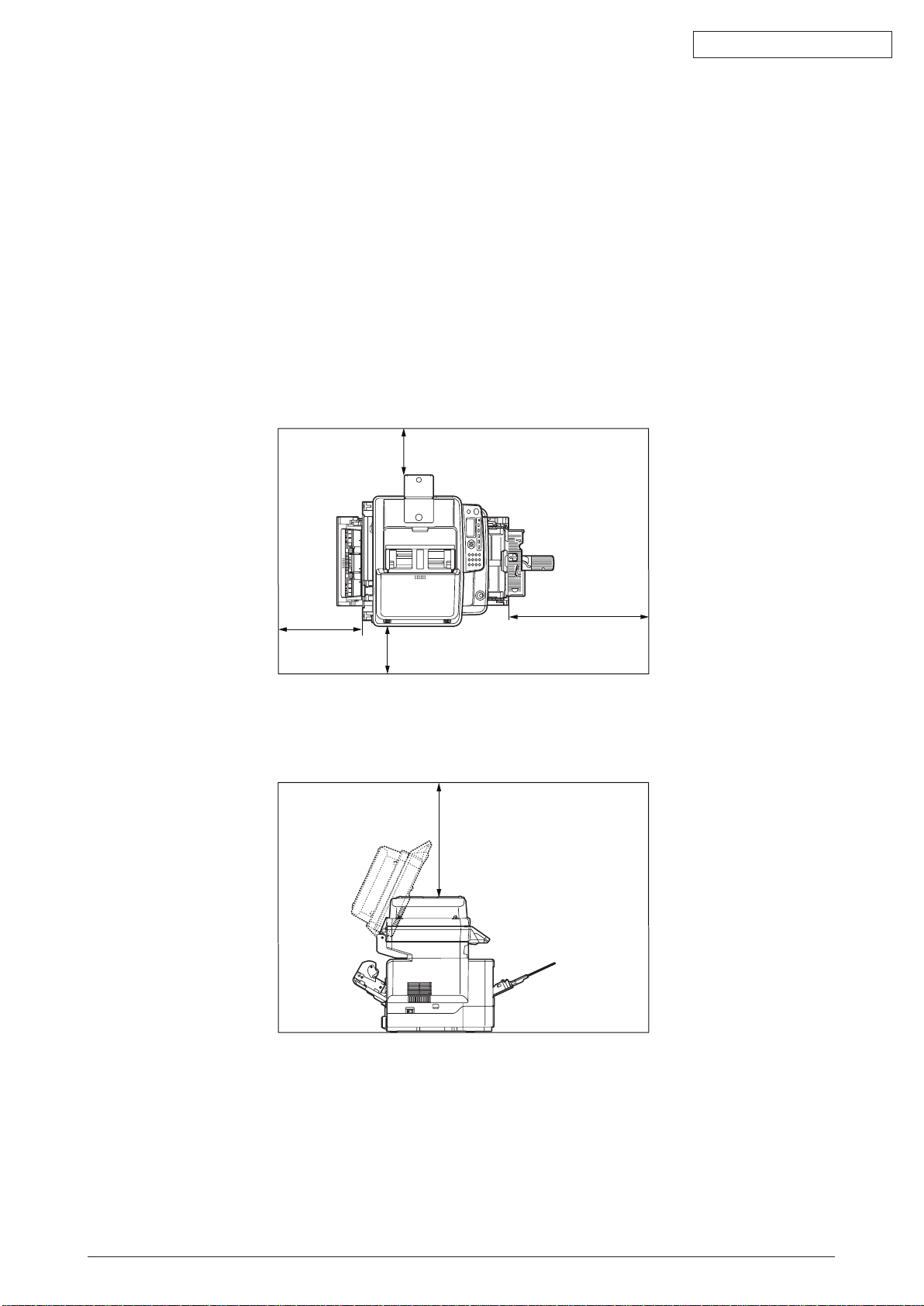
30cm
20cm
20cm
100cm
50cm
3.3 MFP Installation Instructions
•
Install the MFP at a place under the following temperature and humidity:
Amb
Ambient Humidity : 20 to 80% relative humidity
Maximum Wet-Bulb Temperature : 25°C
•
Be careful not to be bedewed.
•
When the MFP is to be installed at a place where the humidity is less than 30%, use a
humidifier or a static electricity prevention mat.
ient Temperature : 10 to 32°C
Installation Space
•
Place the MFP on a flat desk with enough space for the legs of the MFP.
•
Secure enough space around the MFP.
Top View
Oki Data CONFIDENTIAL
Side View
Fig 3.3.1
Fig 3.3.2
44306601TH Rev. 2
33 /
Page 34

3.4 Packed Units and Attachments
•
Confirm whether there are scratches, stains, etc. on the exterior of the machine.
•
Confirm whether there are lacking items, damages, etc. among the accessories.
•
If anything unusual is found, contact the user’s section in charge and follow its
instruction.
Personal injuries may occur.
This MFP weighs about 19kg (MB480).
MFP (main body)
Oki Data CONFIDENTIAL
Fig 3.4.1
Starter Toner Cartridges
Fig 3.4.2
Explain to customers that the toner cartridge and the image drum cartridge are separable.
MFP Software CD-ROM
Power Cord
Warranty and Registration Card
Users Manuals
Note! The printer cable is not included in the accessories.
44306601TH Rev. 2
34 /
Page 35

Pad-Middle
Film
Silica-Gel pac
k
protection pad
protection pad
3.5 Assembly Procedure
3.5.1 MFP Main Body
Remove Protective Equipment
(1) Lift the scanner.
(2) Remove the Pad-Middle.
(3) Remove the Film with two Silica-Gel packs.
Oki Data CONFIDENTIAL
Fig 3.5.1
(4) Remove the eight adhesive tapes on the outside of MFP.
Fig 3.5.2
(5) Open the document cover.
Then remove the four adhesive tapes and two protection pads.
44306601TH Rev. 2
Fig 3.5.3
35 /
Page 36

Paper Cassette
Open Button
A6 size paper
Retainer
MB480
(6) Pull out the paper cassete.
A6 paper
(7) Remove the Retainer and the A6 size paper. (In case of MB480 )
Oki Data CONFIDENTIAL
Fig 3.5.4
(8) Open Multi-purpose Tray. Remove the A6 size paper. (In case of MB470/MB480 )
44306601TH Rev. 2
Fig 3.5.5
36 /
Page 37

Install Image Drum Cartridges
Image Drum Cartridge
Protection sheet
A
B
C
(1) Pull out the image drum cartridge gently.
Note! • Handle the image drum very carefully as it is quite easily
injured.
• Do not expose the image drum cartridge to direct sunshine or bright light
(approximately 1,500 lux or more) . Do not leave it more than 5 minutes under the
room light.
Oki Data CONFIDENTIAL
Fig 3.5.6
(2) Place the image drum cartridge on a flat desk, remove the tape which fastens the protection
sheet and pull it out in the direction of the arrow.
Note! Do not work on the image drum off the desk top.
Fig 3.5.7
(3) Holding the image drum by its top center , lower it into place in the printer locating the pegs (A
& B) at each end into their slots in the sides of the printer cavity (C) .
44306601TH Rev. 2
Fig 3.5.8
37 /
Page 38

Oki Data CONFIDENTIAL
(4) Release the lock by pushing the knob of the toner cover in the direction of the arrow and
remove the toner cover.
Fig 3.5.9
(5) Gently shake the cartridge from end to end several times to loosen and distribute the toner
evenly inside the cartridge.
(6) Remove the wrapping material and peel off the adhesive tape from the underside of the
cartridge.
Fig 3.5.10
44306601TH Rev. 2
38 /
Page 39

Oki Data CONFIDENTIAL
(7) Holding the cartridge by its top center with the coloured lever to the right , lower it into the
printer over the image drum unit from which the toner cover was removed.
Insert the left end of the cartridge into the top of the image drum unit first , push it against
the pins on the drum unit then lower the right end of the cartridge down onto the image
drum unit.
Fig 3.5.11
(8) Pressing gentry down on the cartridge to ensure that it is firmly seated , push the coloured
lever towards the rear of the printer.
This will lock the cartridge into place and release toner into the image drum unit.
Fig 3.5.12
Note! • The starter toner (the toner cartridge attached to the product at the time of(purchase)
• Confirm whether the lever of the toner cartridge is turned fully in the direction of the
44306601TH Rev. 2
c
an print approximately 1,000 sheets of A4 paper in case of 5% coverage.
(1,500 sheets of A4 paper in case of ISO-pattern.)
arrow when Toner Empty Messages are displayed in the LCD.
39 /
Page 40

Oki Data CONFIDENTIAL
Lock
Unlock
Scanning head
OK
Lamp
Scanning head
NG
Unlocking Scanning head
The scan unit is locked during transport to protect the scanning mechanism from
being damaged. Be sure to unlock the scan unit before using the machine.
(1) Open the ADF Doc Lid.
(2) Move the lock switch to the “Unlocked position”.
(The lock switch is located on the left corner on the flat bed.)
(3) Close the ADF Doc Lid.
Fig 3.5.13
Note: If you need to move your MFP or Scanner unit for repair or any other reason, be sure
ock your Scanner before moving. To lock your Scanner, please do the following,
to l
1. Turn off your MFP.
2. If the scanning head is not located at the left end, turn the MFP on to return the
scanning head to the left end. After the scanning head is returned to the left end,
turn the power supply off.
3. Move the lock switch to the “Locked Position”.
44306601TH Rev. 2
Fig 3.5.14
40 /
Page 41

Plate
Cork
Paper Guide
Load Paper in Paper Cassette
Printing face down
Paper Stopper
Paper life display
(1) Pull out the paper cassette.
Note! Do not remove the cork on the plate.
(2
) Conform the paper guide to the paper size and fix it firmly.
Oki Data CONFIDENTIAL
Fig 3.5.15
(3) Shuffle the sheets of paper and arrange up, down, left and right properly.
Fig 3.5.16
(4) Make the printable side down and set the paper.
•
Plac
Note!
Fix the paper by the paper stopper.
(5)
e the paper in front of the paper cartridge.
•
S
et the paper not to exceed “
”mark of the paper guide. (250 sheets weighing 70kg)
▼
(6) Return the paper cassette to the MFP.
44306601TH Rev. 2
Fig 3.5.17
41 /
Page 42

Load Paper in the Manual Feed Opening
Manual Feed Opening
Manual Feeding Guide
Manual feeding
opening
Manual Feeding Guide
Manual Feeding Guide
Manual feeding
opening
Manual Feeding Guide
(1) Put a finger in the dent at the center of the manual feed opening and pull forward.
Fig 3.5.18
(2) Conform the manual feeding guide to the size of the paper.
Oki Data CONFIDENTIAL
(3) Arrange the left and right of the paper.
(MB460) (MB470/MB480)
Fig 3.5.19
(4) Make the printing side up and insert the paper straight to the rear end along the manual
feed guide.
(MB460) (MB470/MB480)
44306601TH Rev. 2
Fig 3.5.20
42 /
Page 43

Oki Data CONFIDENTIAL
Paper Guide
Setup orientation of papers
Face Up
ABC
Setup orientation of papers
Face Down
Align in the upper-left corner
Placing the Original
In the Auto Document Feeder
(1) Make sure your document is free of staples, paper clips and is not tore out.
(2) If you have multiple pages, fan your document(s) to avoid occasional paper jam. The ADF
holds up to 50 pages at one time.
Fig 3.5.21
Place your document(s) with the text FACE UP in the ADF.
(3)
(4) Adjust the Paper Guides to center the document(s) in the ADF.
On the Document Glass
(1) Place your original with the text face down on the document glass.
Fig 3.5.22
44306601TH Rev. 2
Fig 3.5.23
43 /
Page 44

Oki Data CONFIDENTIAL
3.5.2 Power Cable Connection
Conditions for Power Supplies
•
Observe the following conditions:
ernate Current (AC) : 110 ~127VAC(Range 99~140VAC)/220 ~240VAC(Range
Alt
198~264VAC)
Power Supply Frequency : 50Hz or 60Hz±2%
•
Use a voltage regulator when the power supply is not stable.
•
The maximum power consumption of this MFP is 800W. Confirm that the power supply has
sufficient extra capacity.
Table 3.5.1
It may expose you to electric shocks or cause a fire.
• Never fail to switch off the power supply at the time of connection or removal of the electric
cord and earth cable.
• Always connect the earth cable to the earth terminal equipped only for that purpose. Never
connect the earth cable with water pipe, gas pipe, telephone cable earth terminal, lightening
rod, etc.
ways grasp the power plug at the time of connection and removal of the electric cord.
• Al
• Always make sure that the electric plug is inserted fully into the outlet.
• Do not connect or disconnect the electric plug with the wet hand.
• Do not install the electric cord at the place liable to be stepped on and do not put things on
the electric cord.
• Do not bundle up or tie up the electric cord
• Do not use the damaged electric cord.
• Do not put many loads on one electric outlet.
• Do not connect this MFP to the same outlet with other electric machines. Particularly,
erroneous operation may occur by electric noise when the same outlet is shared by the air
conditioner, duplicator, shredder, etc. at the same time. When the same outlet had to be used,
use a noise filter or noise cut transformer on the market.
• Use the attached electric cord only.
• Do not use an extension cord. Use the cord of over rating 15A if you had to use one.
• When you use the extension cord, the MFP may not operate normally due to the drop of AC
voltage.
• Do not shut down the power supply or remove the power plug while printing.
• Disconnect the power cord when the MFP would not be used for some long while due to
consecutive holidays or journey.
As to the connection of the electric cord and earth cable, explain fully to the customer showing
the User’s Manual.
44306601TH Rev. 2
44 /
Page 45

Connect Power Supply Cord
Earth Terminal
Earth Cable
Note! Be certain the power switch is placed in the OFF (O) position.
(1) Insert the electric cord in the MFP.
(2) Connect the earth wire to the earth terminal of the AC power source outlet.
(3) Connect the AC power cord insertion plug to the AC power source outlet.
Oki Data CONFIDENTIAL
Press ON (I) of Power Switch
Fig 3.5.24
Fig 3.5.25
44306601TH Rev. 2
45 /
Page 46

Memory Cover
Knob
3.5.3 Installation of Optional Components
OI
(1) Extension Memory Installation
Fig 3.5.26
Table 3.5.2
Type On-board Memory slot Total
N/A (Standard) 64MB - 64MB
64MB option
DIMM
MEM64D
256MB option
DIMM
MEM256D
64MB 64MB 128MB
64MB 256MB 320MB
Oki Data CONFIDENTIAL
Note! • You m
•
A 64MB memory is installed as standard in the memory slot. If you use a 256MB
ust use genuine Oki Original. Otherwise, the memory will not work.
memory, remove the 64MB memory before use.
Switch the power supply of the MFP off and pull out the electric cord.
Note! If installed with the switch on, an electric shock or a trouble to the MFP may occur.
Fig 3.5.27
Open the memory cover.
1) Release the lock by pushing the knob of the memory cover in the direction of the arrow and
open the memory cover.
44306601TH Rev. 2
Fig 3.5.28
46 /
Page 47

Oki Data CONFIDENTIAL
Memory Cover
Install the memory.
Note! Do not touch electronic parts and connector terminal.
1) Neutralize static electricity by letting the bag touch the metal part before taking out the
memory from the bag.
ay attention to the direction of the memory. There is a cut on the terminal part of the
2) P
memory to fit it into the connector of the slot.
3) Insert the memory in the empty slot and bring it down to the circuit board side.
Fig 3.5.29
Close the memory cover.
1) Close the memory cover. Confirm that it is firmly locked.
44306601TH Rev. 2
Fig 3.5.30
47 /
Page 48

(2) Installation of second tray unit
O I
Holes in the
printer bottom
Protrusions
This tray is intended to increase the amount of paper that can be loaded in the MFP. It holds
530 sheets of 70kg ream weight paper, allowing to print 1110(MB480) sheets continuously
when combined with the standard paper cassette and multi-purpose tray.
Turning OFF the MFP power and disconnecting the power cord
Note! If an expansion memory is installed with the power switched ON, the MFP may be
oken.
br
Oki Data CONFIDENTIAL
Fig 3.5.31
Fig 3.5.32
Placing the MFP on the second tray unit.
Note! The MFP weighs Approx. 19kg (MB480).
1) Align the holes in the bottom of the MFP to the protr
2) Place the MFP gently on the second tray unit.
usions of the second tray unit.
44306601TH Rev. 2
Fig 3.5.33
48 /
Page 49

Oki Data CONFIDENTIAL
Cover-piece
Cover-piece
B460/B470 B480
2nd-piece
2nd-piece
3) Remove the four Cover-pieces in the direction of the arrow. Do not put or drop the
Cover-pieces inside the MFP.
Fig 3.5.34
4) Attach the two 2nd-pieces as shown in Fig. 3.5.35.
To detach the second tray unit, follow the same procedure inversely.
Fig 3.5.35
44306601TH Rev. 2
49 /
Page 50

Oki Data CONFIDENTIAL
3.5.4 Confirm the Recognition of Option
In order to confirm that the items of option are correctly installed, conduct the menu map
printing referring to “3.6 Configuration Page Print”.
(1) Confirm Recognition of Additional Memory
Confirm the contents of the configuration pages.
Confirm the total memory size displayed as “TOTAL MEMORY SIZE” in the header portion.
Fig 3.5.36
(2) Confirm Recognition of second tray
Confirm the contents of the configuration pages.
Confirm the displayed as "Tray 2" in the header portion.
Fig 3.5.37
44306601TH Rev. 2
50 /
Page 51

3.6 Configuration Page Print
Make sure that the MFP operates normally.
(1) Set sheets of A4 paper in the tray.
(2) From the panel menu, select "Menu".
(Press the down button to go to "Menu" and then press the enter button.)
(3) Select "Print Information".
(Press the down button to go to "Print Information" and then press the enter button.)
(4) Select "Configuration".
(5) Select "Execute".
(Sample) MB460
Oki Data CONFIDENTIAL
44306601TH Rev. 2
Fig 3.6.1
51 /
Page 52

(Sample) MB470
Oki Data CONFIDENTIAL
44306601TH Rev. 2
Fig 3.6.2
52 /
Page 53

(Sample) MB480
Oki Data CONFIDENTIAL
44306601TH Rev. 2
Fig 3.6.3
53 /
Page 54

Oki Data CONFIDENTIAL
3.7 Network Information Print
Confirm the network information print.
(1) Push the TEST switch beside the network connector on the back of the MFP for 5 seconds
and release. Then the network information will be printed.
(Sample) In case of MB460
44306601TH Rev. 2
Fig 3.7.1
54 /
Page 55

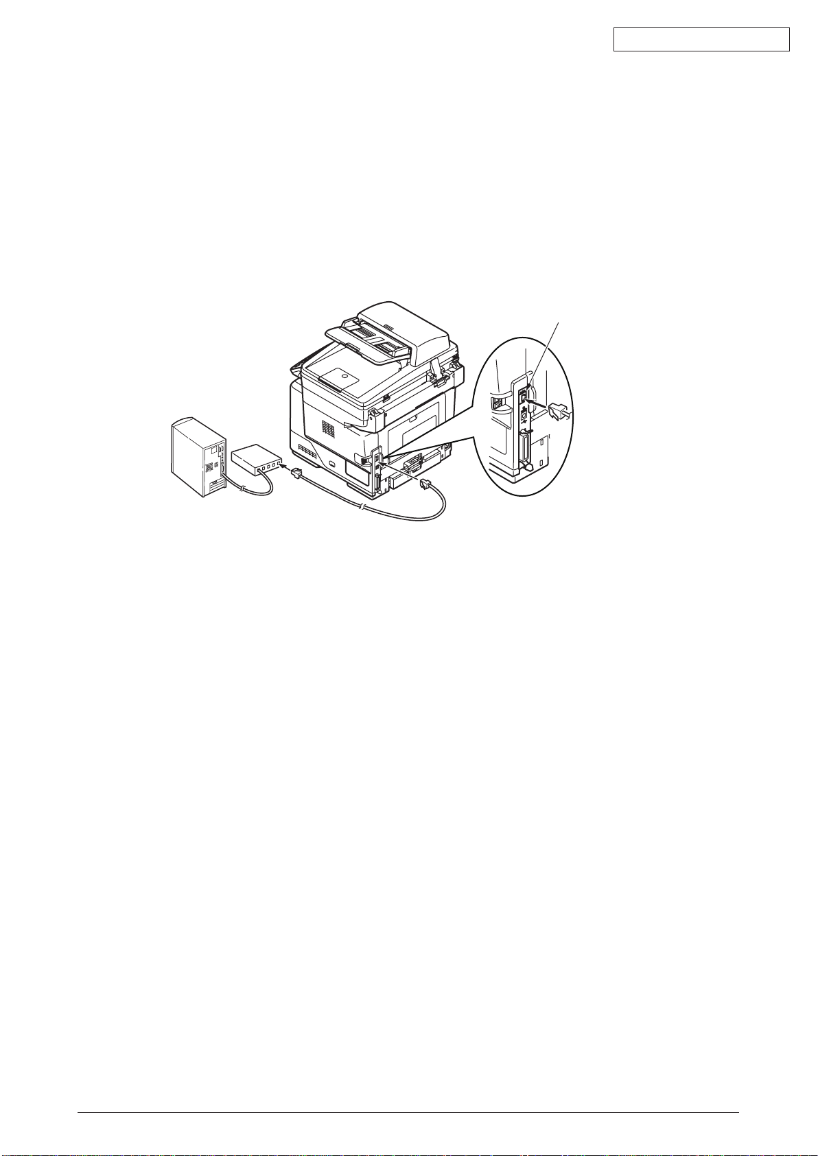
UBS Interface
Connector
3.8 Connection Procedures
<USB Connection>
Prepare a USB Cable.
Note! • The cable of the MFP is not attached. Users should buy seperately.
•
•
Obtain the cable of USB specification by yourself.
Use the USB cable of Hi-Speed specification in case the connection is to be made
sing “HI-Speed” mode of USB2.0.
u
Oki Data CONFIDENTIAL
Fig 3.8.1
Switch off the power of the
Memo Although the USB cable can be connected or removed with the switch of the
computer and printer on, switch off the power of the MFP at this step in order to
ensure installation of the MFP driver and USB driver later.
Connect the
(1) Plug the USB cable into the USB interface connector of the MFP.
(2) Plug the USB cable into the USB interface connector of the computer.
Note! Be careful not to insert the USB cable into the network interface connector.
Or e
MFP
with the computer.
lse it may cause troubles.
MFP
and computer.
44306601TH Rev. 2
Fig 3.8.2
55 /
Page 56
<LAN Cable Connection>
Network Interface Connector
Prepare the LAN cable.
Switch off the power of the MFP and computer.
Connect the computer and MFP.
(1) Plug the Ethernet cable into the network interface connector of the MFP.
(2) Plug the Ethernet cable into the hub.
Oki Data CONFIDENTIAL
Fig 3.8.3
44306601TH Rev. 2
56 /
Page 57

TEL Connector
LINE Connector
TEL
LINE
<TEL cable. Line Cable Connection>Note! only MB470/MB480
Prepare the TEL cable and Line cable.
Preparing cores
Memo Use two longer ones of two kinds cores packed with MFP.
How to attach a cores
Memo Wind the TEL cable and Line cable on each core 1 time and then close the core
cases to fix them. The cores must be about 80~100mm away from the each connector.
Oki Data CONFIDENTIAL
The places for connecting each cables
Fig 3.8.4
Fig 3.8.5
44306601TH Rev. 2
57 /
Page 58

The state after connecting
Use for Fax.
(Only MB470/MB480)
for TEL
for LINE
for USB
for LAN
Oki Data CONFIDENTIAL
Fig 3.8.6
Table 3.8.1
Cable Core Name Part No. Core shape Winding count
for TEL SFT-59SN 1051007C0001 Long Type 1
for LINE SFT-59SN 1051007C0001 Long Type 1
Do not also connect to switchboard directly or exclusive use line without any conversion
※
MB460 MB470 MB480
X
X
equipment.
44306601TH Rev. 2
58 /
Page 59

3.9 Checking of User Paper
Set the medium the user uses, set up media type/weight, conduct menu map/demo print and
confirm that the toner does not peel off.
Oki Data CONFIDENTIAL
Table 3.9.1
Types Weight
55kg(64g/m2) Light
Regular
paper*3
Postcard*4 - - - -
Envelope*4 - - - -
Label paper - Heavy Labels Labels
*1
*2
55-64kg(64-74g/m2) Medium Light Medium Light
65-75kg(75-87g/m2) Medium Medium
76-89kg(88-104g/m2) Medium Heavy Medium Heavy
90-105kg(105-120g/m2) Heavy Heavy
: The set-up of the media type at the time of shipment from the factory is “Plain”.
: Thickness and type of paper can be set up by the printer driver. When they are set up
Setting values of the MFP Setting*2 for [Media weight]
Media weight Media type*1
Plain
of the printer driver
Light
by the printer driver, the printer driver set-up has priority. When “Automatic Selection” is
selected by “Paper Feed Method” of the printer driver or when “Printer Set-up” is selected
by “Paper Thickness”, printing is made by the set-up of the MFP.
*3
: Thickness of paper for both side printing is 55~90kg in weight (64~105g/m2).
*4
: Set-up of media weight and media type is not necessary for postcards and envelopes.
44306601TH Rev. 2
59 /
Page 60

4. RePlaCeMenT of PaRTs
OFF
ON
Shutting
off
Reconnecting
Earth cable
Earth terminal
Warning
This section explains the field replacement procedures for parts, assemblies and component
units. While those replacement procedures refer to the disassembling of parts, follow the same
procedures inversely for reassembling them.
The part numbers (1, 2, etc.) employed in this manual are different from those assigned in the
corresponding configuration diagrams of Disassembly for Maintenance (44306601TL) and
RSPL (44306601TR/44306621TR/44306641TR).
4.1 Precautions on the replacement of parts
(1) Prior to replacing a part, be sure to disconnect the AC cord and interface cable.
(a) To disconnect the AC cord, always follow the procedure described below:
Switch the power switch of printer off “O”.
Disconnect the AC insertion plug of the AC power cord from the AC power source.
Disconnect the earth wire from the earth terminal of the AC power source outlet.
Disconnect the AC cord and the interface cable with the printer.
Risk of Electric Shock
Oki Data CONFIDENTIAL
There is a risk of electric shock during replacement of the low voltage power supply.
Use insulating gloves or avoid direct contact with any conducting part of the power supply,
and caution should be exercised during replacement.
The capacitor may take one minute to complete discharge after the AC cord is unplugged.
Also, there is a possibility that the capacitor doesn’t discharge because of a breakage of
the PCB, etc., so remember the possibility of electric shock to avoid electric shock.
(b) To reconnect the printer, always follow the procedure described below:
Connect the AC cord and the interface cable with the printer.
Connect the earth wire to the earth terminal of the AC power source outlet.
Connect the AC power cord insertion plug to the AC power source outlet.
Switch the power switch of printer on “I”.
Fig 4.1.1
(2) Do not disassemble the MFP as long as it is operating normally.
(3) Limit disassembly to a necessary minimum. Do not remove other parts than those specified in
the part replacement procedure.
(4)
Use the designated maintenance tools.
(5) Conduct disassembly by following the specified sequential order. Failure to observe this order
could damage the parts.
Screws, collars and other small parts should be attached provisionally to their original
(6)
positions, since they are liable to be lost.
(7)
When handling a microprocessor, ROM, RAM and other ICs and circuit boards, do not wear
gloves that tend to generate static electricity.
(8)
Printed-circuit boards should not be placed directly on an equipment or floor.
44306601TH Rev. 2
60 /
Page 61
Oki Data CONFIDENTIAL
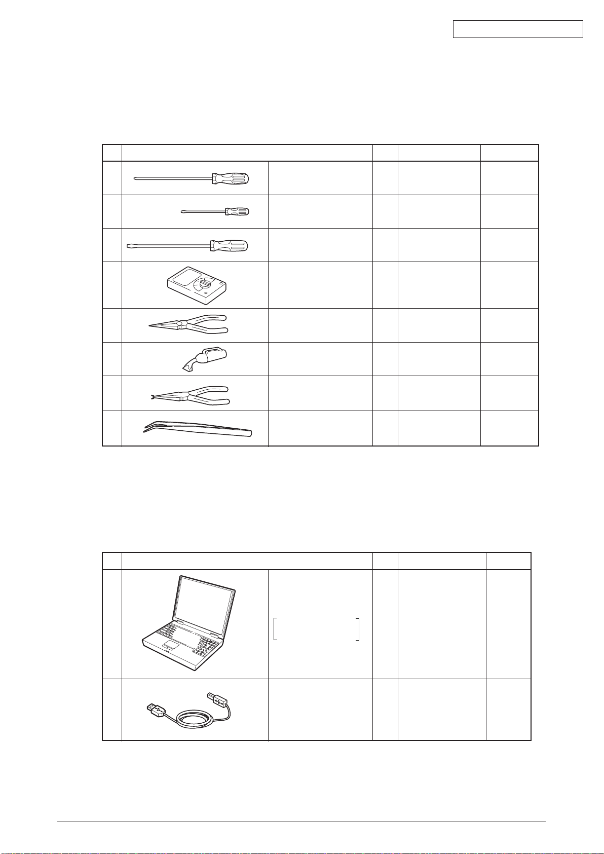
No. Q' ty Place of use RemarksService Tools
2 USB cable 1
1
Laptop computer
Must have maintenance
utilities installed
1
No. Q' ty Place of use
Remarks
Service Tools
1
2
3
4
5
6
No. 2-200 Philips
screwdriver, Magnetized
No. 3-100 screwdriver
No. 5-200 screwdriver
Digital multimeter
Pliers
E-ring pliers
Handy cleaner
1
1
1
1
1
1
Tweezers
Curved-tip
type
Refer to the
following note.
1
3~5 mm screws
7
8
1
[Maintenance Tools]
Table 4.1.1 indicates the tools necessary to replace printed-circuit boards and component units.
Table 4.1.1
Note:
Use a vacuum cleaner dealing with toner. Using a common vacuum cleaner may cause fire.
Table 4.1.2 indicates the tools necessary for using maintenance utilities.
Table 4.1.2
44306601TH Rev. 2
61 /
Page 62

4.2 Parts layout
A
A
A’
A’
Stacker-Cover-Assy
Cover-Side-R
Cover-Side-L
Plate-Base-PCB
Plate-Assy-Base
Motor-Fan
Duplex
Rear-Cover-Assy
Fuser-Assy
OPE
Cover-Assy
Guide-Paper-Duplex
GuidePaper-R
Manual-Assy
Front-Guide-Assy
CU board
Toner cartridge
Low voltage
power board
High voltage
power board
Paper cassette
Image drum cartridge
This section explains the main parts layout of the equipment.
MB460
Oki Data CONFIDENTIAL
44306601TH Rev. 2
Fig 4.2.1
62 /
Page 63

MB470
A
A
A’
A’
Stacker-Cover-Assy
Cover-Side-R
Cover-Side-L
Plate-Base-PCB
Plate-Assy-Base
Motor-Fan
Rear-Cover-Assy
Fuser-Assy
OPE
Cover-Assy
Guide-Paper-Duplex
GuidePaper-R
Manual-Assy
Front-Guide-Assy
CU board
Toner cartridge
Low voltage
power board
High voltage
power board
Paper cassette
Image drum cartridge
Oki Data CONFIDENTIAL
44306601TH Rev. 2
Fig 4.2.2
63 /
Page 64

MB480
A
A
A’
A’
Stacker-Cover-Assy
Cover-Side-R
Cover-Side-L
Plate-Base-PCB
Plate-Assy-Base
Motor-Fan
Duplex
Rear-Cover-Assy
Fuser-Assy
OPE
Cover-Assy
Guide-Paper-Duplex
GuidePaper-R
Manual-Assy
Front-Guide-Assy
CU board
Toner cartridge
Low voltage
power board
High voltage
power board
Paper cassette
Image drum cartridge
Oki Data CONFIDENTIAL
44306601TH Rev. 2
Fig 4.2.3
64 /
Page 65

[Base unit]
Photo Interrupter
Roller-Pick-Up
Roller-Feed-Now
Guide-Cassette-L
Guide-Cassette-R
Plate-Base
Gear-Assy-Clutch
MB460/MB470
Oki Data CONFIDENTIAL
44306601TH Rev. 2
Fig 4.2.4
65 /
Page 66

Photo Interrupter
Roller-Pick-Up
Roller-Feed-Now
Guide-Cassette-L
(530sht)
Guide-Cassette-R
(530sht)
Plate-Base
Gear-Assy-Clutch
[Base unit]
MB480
Oki Data CONFIDENTIAL
44306601TH Rev. 2
Fig 4.2.5
66 /
Page 67

Oki Data CONFIDENTIAL
4.3 Parts replacement method
This section explains the replacement method of the parts and assemblies that are shown in the
following disassembling diagram.
The explaining diagram of parts replacement procedure is MB470.
Replace part after performing the following operation.
(1) Unplug the AC power cord from the main unit inlet by the disconnected status of power
switch.
(2) U
nplug the interface cable from the main unit.
44306601TH Rev. 2
67 /
Page 68

4.3.1 Detachment methods of the scanner and printer
4.3.1.1 Cover-Side-R
(1) Lift the scanner.
(2) Open the Rear-Cover-Assy.
(3) Open the Stacker-Cover-Assy.
(4) Take out the image drum cartridge.
(5) Remove the screw (Black)
(6) Installing is performed by the inverse procedure with removing.
(Note on removing / installing)
1. Beware of not to touch the DC motor inattentively (Do not rotate motor).
and the screw (Silver) . Remove the Cover-Side-R .
Oki Data CONFIDENTIAL
44306601TH Rev. 2
Fig 4.3.1
68 /
Page 69

4.3.1.2 Cover-Side-L
(1) Lift the scanner.
(2) Open the Rear-Cover-Assy.
(3) Open the Stacker-Cover-Assy.
(4) Take out the image drum cartridge.
(5) Remove the screw (Black)
(6) Installing is performed by the inverse procedure with removing.
Note! Attach the Label Motor-Fan on the outside that is obviously to be seen.
. Remove the Cover-Side-L .
Oki Data CONFIDENTIAL
44306601TH Rev. 2
Fig 4.3.2
69 /
Page 70

4.3.1.3 FAX Board (In case of MB470/480 )
(1) Remove the Cover-Side-R . (Refer to 4.3.1.1 )
(2) Remove the two screws(silver)
(3) Remove the cable connector
(4) Remove the three screws(silver)
(5) Remove the Board-FAX
(Note on removing / installing)
1. Beware of not to touch the DC motor inattentively (Do not rotate motor).
.
. Remove the Plate-Shield-Cover-FAX .
from the Board-FAX .
.
Oki Data CONFIDENTIAL
Note : When replacing the Board-FAX, make sure
that there is a marking on the connector.
44306601TH Rev. 2
Fig 4.3.3
70 /
Page 71
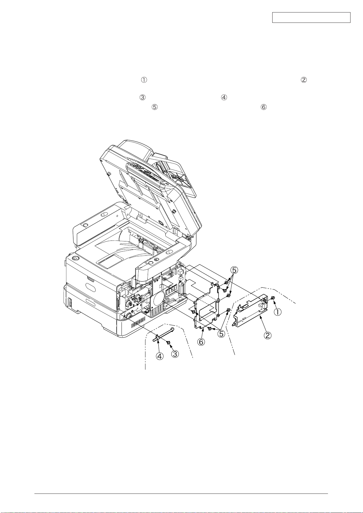
Oki Data CONFIDENTIAL
MB460
MB470/MB480
4.3.1.4 Detachment methods of the scanner and printer
(1) Remove the Cover-Side-R and the Cover-Side-L. (Refer to 4.3.1.1/ 4.3.1.2)
(2) Remove the Plate-Shield-Cover-Fax and cable. (Refer to 4.3.1.3 ) (In case of MB470/MB480 )
(3) Remove the screw(silver)
case of MB470/MB480 )
(4) Remove the screw(silver)
(5) Remove the six screws(silver)
. Remove the Plate-Shield-Base-FAX(with Board-FAX) . (In
. Remove the Cable-clamp . (In case of MB460 )
. Remove the Plate-Shield-Cover-CU .
44306601TH Rev. 2
Fig 4.3.4
71 /
Page 72

(6) Remove the Scanner-cable connector from the Board-CU.
(7) Remove the four screws(silver)
so as not to allow the scanner to tilt back).
.(hold the front side of the stay on each side of the printer
Oki Data CONFIDENTIAL
Fig 4.3.5
(8) Put the scanner back in its original horizontal position.
(9) By holding the scanner by the right and left stays and vertically lifting it up, separate the
scanner from the printer.
44306601TH Rev. 2
Fig 4.3.6
72 /
Page 73

Oki Data CONFIDENTIAL
Lever
ADF top cover
Frame Assy
4.3.2 Scanner
4.3.2.1 Detachment of the paper tray
(1) Gently open the ADF top cover.
(2) Turn the lever in the direction of the arrow to put the frame assembly and the paper tray
upright.
(3)
Remove the two screws(black)
, and then the paper tray .
44306601TH Rev. 2
Fig 4.3.7
73 /
Page 74

Oki Data CONFIDENTIAL
A
B
B
Driver
4.3.2.2 Detachment of Pad
(1) Open the ADF top cover. (Refer to 4.3.2.1 )
(2) As in the figure under, insert the tip of the small minus driver softly to the dent of the pad
case. By this operation, the inner hooks of pad is removed in direction of the arrow (A).
Note: I
(3) Push another side of pad forward in direction of the arrow (B) with the tool inserted.
n order to cause damage to the surface of roller, please take attention to use the
ol when this operation.
to
Fig 4.3.8
(4) Exchange to the new pad in the direction of the arrow.
44306601TH Rev. 2
Fig 4.3.9
Fig 4.3.10
74 /
Page 75

4.3.2.3 Removing ADF PCBA
ADF top Cover
Lever
(1) Gently open the ADF top cover.
(2) Remove the two screws(black)
(3) Remove the two screws(black)
(4) Turn the lever in the direction of the arrow to put the frame Assembly
upright.
(5) Remove the two screws(black)
(6) Restore the frame Assembly
(7) Release the frame Assembly
scanner to remove the Assembly and the paper tray .
(8) Remove the three screws(black)
(9) Unplug all the connectors and remove the ADF PCBA
to remove the cover-gear .
.
.
and the paper tray in their original positions.
from the hook near its supporting point on each side of the
to remove the ground plate , and .
.
Oki Data CONFIDENTIAL
and the paper tray
44306601TH Rev. 2
Fig 4.3.11
75 /
Page 76

Oki Data CONFIDENTIAL
Finger nail placed
FFC cable
of the LCD
FFC cable
Finger nail placed
Seven hooks
(A)
4.3.2.4 Removing operation panel
(1) By putting nails of each hand in the space at the portion of the fit between the operation
panel Assembly and the flatbed on the side of the hand, disengage from the scanner the
four upper hooks on the operation panel Assembly in direction of the arrow (A).
(2) Pull the FFC cable straight out of the connector on the back of the operation panel.
Note: Be careful not to remove or insert the FFC cable at an angle from the connector on
the back of the operation panel Assembly their terminals are damaged.
Removing operation panel PCBA
(1) Pull the FFC cable out of the LCD straight in the direction of the arrow.
(2) Remove the two screws(black)
(3) Remove the three screws (black)
Note: Removing or inserting the FFC cable at an angle from the connector on the back of
the operation panel Assembly damages their terminals.
. Remove the Panel-Cover-Frame .
.Remove the operation panel PCBA .
44306601TH Rev. 2
Fig 4.3.12
76 /
Page 77

4.3.2.5 Removing the MPCBA
Stay_L
Contacting
Relationship between
Projection and Side
Projection (on each
shield metal plate)
(1) Turn the scanner unit upside down.
(2) Pull up the stays L and R at the same time until they stop.
(3) Remove the six screws (black)
(4) Remove the shield-USB
(5) Remove the four screws (black, with washers)
(6) Disconnect all the connectors and remove the MPCBA board
Note: Be sure to slowly move the both stays L and R at the same time. If moved separately,
they may be broken.
To re
Pay
Hoo
assemble shield metal plates, position the shield metal plates in a manner so
that every projection of each of the shield metal plates contacts the outside surface of
the mating part. (See the illustration below.)
ing attention to the fixing position of the core. (See the photo at the bottom of the
next page.)
k the bent end of the shield-USB
the direction of the arrow to reassemble it. (See the photo at the top left of the next
page.)
and remove the MPCBA-cover .
by turning it in the direction of the arrow.
and remove the top shield Assembly .
into the top shield Assembly and turn it in
Oki Data CONFIDENTIAL
.
44306601TH Rev. 2
Fig 4.3.13
77 /
Page 78

Insert the bent end into the square
Oki Data CONFIDENTIAL
FG cable (fixed together)
Shield-USB &FG cable
FG cable (fixed together)
Two FG cables
Fig 4.3.14 Fig 4.3.15
To the scanning sensor
To the operation panel
To the printer (USB)
44306601TH Rev. 2
Core
Fig 4.3.16
To the
FB motor
There is no fan
To ADF
78 /
Page 79

4.3.2.6 Removing ADF Assembly
(Long type)
Lower
ADF connector
(1) Remove the two screws(black) to remove the base stopper upward at an angle.
Oki Data CONFIDENTIAL
Note: Unlike the other screws used in the printer, the screws
Fig 4.3.17
(2) Reverse the scanner and put the stays L and R upright.
(3) Remove the six screws(black)
(4) Remove the ADF connector.
and then the MPCBA cover .
are long.
44306601TH Rev. 2
Fig 4.3.18
79 /
Page 80

Oki Data CONFIDENTIAL
Tweezers
Tweezers
Cross-Secton
(5) Unthread the cable through its guide groove.
(6) Turn over the scanner again and open the document cover (the ADF assembly 5).
(7) Slightly lift the ADF assembly
by inserting closed curved-tip tweezers and, in the direction of the arrow, lightly pressing the
tweezers. Lift and remove the ADF assembly .
. As illustrated, unlock each hinge of the ADF assembly
Note: For the structure of each hinge joint of the ADF assembly
view shown below.
Fig 4.3.19
(8) Turn the ADF Assembly upside down.
(9) Remove the six screws(black)
and then the hinge Assembly .
, see the cross-section
44306601TH Rev. 2
Fig 4.3.20
80 /
Page 81

4.3.2.7 Removing the Window-ADF
Document cover
Sheet
(1) Gently open the document cover.
(2) Flip the sheet and remove five screws (black)
(3) Remove the Window-ADF
Note: Be careful not to crease the sheet.
.
Oki Data CONFIDENTIAL
.
Be c
When replacing the Window-ADF
areful not to damage the glass surface with tools.
protective film from the new Window-ADF to attach.
with a new Window-ADF , remove the white
44306601TH Rev. 2
Fig 4.3.21
81 /
Page 82

Oki Data CONFIDENTIAL
Stacker-Cover-Assy
Cable
Hook B
Hook A
SLA
(Selfoc Lens Array)
4.3.3 Printer
4.3.3.1 LED Head
(1) Lift the scanner.
(2) Open the Stacker-Cover-Assy.
(3) Remove the Holder-Head
(4) Firstly open Hook A by narrow direction and then remove it. Secondly remove Hook B then
remove LED Assy
(5) Remove cable from the connector of LED Assy
(6) Installing is performed by the reverse procedure with removing.
Note! Beware of not to touch or press the SLA parts of LED Head directly.
. (At this moment, the two springs can be also removed jointly.)
.
.
44306601TH Rev. 2
Fig 4.3.22
82 /
Page 83

Stacker-Cover-Assy
Latch
②
4.3.3.2 Roller-Transfer
(1) Lift the scanner.
(2) Open the Stack-Cover –Assy
(3) Remove latches in the 2 places of Gear-TR
not add any unnecessary pressure while removing the latch.)
(4) Slightly slide the Roller-transfer
from the contact of Frame-Assy-Lower. Remove the latches on the 2 places of Gearing-TR
of Gear.
(5) Hold the Bearing-TR
moment, Gear-TR is also removed.)
(6) Installing is performed by the inverse procedure with removing.
(Note on removing / installing)
eware of not to touch the DC motor inattentively (Do not rotate motor).
1. B
2. While installing, pay attention to the up-and-down direction of Bearing-TR
3. Operating carefully, not to touch Roller-Transfer
on the both side, and then lift up the Roller-Transfer . (At this
to the right side and remove the post on the top of gear
and Bearing-TR on the conversing side. (Do
surface.
Oki Data CONFIDENTIAL
.
44306601TH Rev. 2
Fig 4.3.23
83 /
Page 84

Oki Data CONFIDENTIAL
PW
1
2
PNLUSB
HEAD
24
1
1
2
8
7
LAN
USB
CENT
1
19 36
18
NICSW
20
19
110
FAXIF
86M-
DM
1 10
1
1
1
8
6
1
7
2 12 1
2NDTRAY
HVIF
RAMDIMM
1
2
27
SON
EXRCO
2
THERM
RCLT
HCLT
MCLT
PE
22
10
1
22
10
1
AB
AB
K
A
A
IC6
28
13941
199
24042
200
Connector for Clutch(MPT)
Connector for Scanner
Connector for LED HEAD
Connector for High voltage power board
Connector for Low voltage power board
Connector for FAX
Connector for DC Motor
Connector for 2nd Tray
Connector for Clutch(Regist)
Connector for Clutch(Hopping)
4.3.3.3 CU Board
(1) Remove the Cover-Side-R. (Refer to 4.3.1.1)
(2) Remove the Plate-shield-Cover-FAX(Refer to 4.3.1.3 ) (In case of MB470/480 )
(3) Remove the Plate-Shield-Base-FAX(with Board-FAX).(Refer to 4.3.1.4 (3)) (In case of
MB470/480 )
Remove the Cable-clamp . (Refer to 4.3.1.4(4)) (In case of MB460 )
(4)
(5) Remove the Plate-Shield-Cover-CU.(Refer to 4.3.1.4(5))
(6) Remove the all cable connector.
(7) Remove the two screws (Silver)
(8) Installing is performed by the inverse procedure with removing.
(Note on removing / installing)
1. Beware of not to touch the DC motor inattentively (Do not rotate motor).
2. Beware of not to tuck down the cable while installing the Plate-Cover-Shield-CU .
,two screws (Silver) . Remove the CU board .
44306601TH Rev. 2
Fig 4.3.24
Fig 4.3.25
84 /
Page 85

Oki Data CONFIDENTIAL
Claw B
Claw A
4.3.3.4 OP Cover Assy
(1) Lift the scanner.
(2) Open the Rear-Cover-Assy.
(3) Open the Stacker-Cover-Assy.
(4) Remove the Cover-Side-R and the Cover-Side-L. (Refer to 4.3.1.1 / 4.3.1.2)
(5) Open the Cover-Assy-MPT.
(6) Pull Claw A by the arrow direction. Remove the clamp by pushing Claw B as the arrow direction.
Remove the OPE Cover Assy
(7) Installing is performed by the reverse procedure with removing.
(Note on removing / installing)
1. Beware of not to touch the DC motor inattentively (Do not rotate motor).
.
44306601TH Rev. 2
Fig 4.3.26
85 /
Page 86

Oki Data CONFIDENTIAL
A
A
B
B
Driver
Pay attention not to let Separating- Pad- Assy pop out to
your front side while installing MPT-Assy.
C
Frame-Assy-Lower
4.3.3.5 MPT-Assy (In case of MB460, it is Manual-Assy)
(1) Lift the scanner.
(2) Open Rear-Cover-Assy.
(3) Open Stacker-Cover-Assy.
(4) Remove Cover-Side-R and Cover-Side-L. (Refer to 3.3.3/3.3.4)
(5) Remove OPE Cover-Assy. (Refer to 3.3.7)
(6) Remove the clamp of claw by pushing by arrow A direction, and then remove Cover-Lever-
Lock
(7) Remove the 2 screws (Black)
(8) Open the Frame-Assy-Lower by arrow B direction, and then remove Lever-Lock-Top
(9) Holding up MPT-Assy
(10) Installing is performed by the inverse procedure with removing.
.
.
(Manual-Assy ) and remove it.
.
Note! While removing the Lever-Lock-Top
between the Frame-Assy-Lower and Lever-Lock-Top and press the driver by Arrow C
direction.
(Note on removing / installing)
1. Beware of not to touch the DC motor inattentively (Do not rotate motor).
, it is easy to remove it by inserting the driver
Fig 4.3.27
44306601TH Rev. 2
86 /
Page 87

Oki Data CONFIDENTIAL
4.3.3.6 Front-Guide-Assy
(1) Lift the scanner.
(2) Open Rear-Cover-Assy.
(3) Open Stacker-Cover-Assy.
(4) Remove Cover-Side-R and Cover-Side-L. (Refer to 3.3.3/3.3.4)
(5) Remove OPE Cover-Assy. (Refer to 3.3.7)
(6) Remove MPT-Assy. (Refer to 3.3.9)
(7) Remove the clamp of claw by pushing by arrow direction, and then remove Cover-Paper-R
(8) Remove the 2 screws (Black)
(9) Installing is performed by the inverse procedure with removing.
(Note on removing / installing)
eware of not to touch the DC motor inattentively (Do not rotate motor).
1. B
. Remove Front-Guide-Assy .
.
44306601TH Rev. 2
Fig 4.3.28
87 /
Page 88

4.3.3.7 Roller-Assy-Feed
(1) Lift the scanner.
(2) Open Rear-Cover-Assy.
(3) Open Stacker-Cover-Assy.
(4) Remove Cover-Side-R and Cover-Side-L. (Refer to 3.3.3/3.3.4)
(5) Remove OPE Cover-Assy. (Refer to 3.3.7)
(6) Remove MPT-Assy. (Refer to 3.3.9)
(7) Remove Guide-Assy-Front. (Refer to 3.3.10)
(8) Remove Roller-Assy-Feed
(9) Installing is performed by the inverse procedure with removing.
(Note on removing / installing)
eware of not to touch the DC motor inattentively (Do not rotate motor).
1. B
by arrow direction.
Oki Data CONFIDENTIAL
44306601TH Rev. 2
Fig 4.3.29
88 /
Page 89

4.3.3.8 Guide-Paper-Duplex
(1) Lift the scanner.
(2) Open the Rear-Cover-Assy.
(3) Open the Stacker-Cover-Assy.
(4) Remove Cover-Side-R and Cover-Side-L. (Refer to 3.3.3/3.3.4)
(5) Remove OPE Cover-Assy. (Refer to 3.3.7)
(6) Remove MPT-Assy. (Refer to 3.3.9)
(7) Remove Front-Guide-Assy. (Refer to 3.3.10)
(8) Remove Roller-Assy-Feed. (Refer to 3.3.11)
(9) Remove Duplex-Assy.
(10) Remove the 2 screws (Black)
(11) Installing is performed by the reverse procedure with removing.
(Note on removing / installing)
eware of not to touch the DC motor inattentively (Do not rotate motor).
1. B
. Remove Guide-Paper-Duplex .
Oki Data CONFIDENTIAL
44306601TH Rev. 2
Fig 4.3.30
89 /
Page 90

4.3.3.9 Stacker-Cover-Assy
Claw A
Claw B
(1) Detachment methods of the scanner and printer ( Refer to 4.3.1.4 )
(2) Remove the clamp by pushing claw A as the arrow direction . Pull the Cover-Blank-L
upward remove it.
(3) Remove the clamp by pushing claw B as the arrow direction . Pull the Cover-Blank-R
upward remove it.
(4) Remove the LED cable from the CU board.
(5) Remove the screw(Silver)
(6) Open the Stacker-Cover-Assy
from the supporting point of Frame-Assy-Lower.
(7) Installing is performed by the reverse procedure with removing.
(Note on removing / installing)
1. Beware of not to touch the DC motor inattentively (Do not rotate motor).
.
by the arrow direction and remove Stacker-Cover-Assy
Oki Data CONFIDENTIAL
44306601TH Rev. 2
Fig 4.3.31
90 /
Page 91

4.3.3.10 Motor-DC-Main
Piece-Guide
(1) Detachment methods of the scanner and printer ( Refer to 4.3.1.4 )
(2) Remove Stacker-Cover-Assy. (Refer to 4.3.3.9)
(3) Remove the three screws(black)
(4) Remove the connector
(5) Remove the three screws (Silver)
(6) Remove the Motor-DC-Main
(7) Installing procedure is performed by the opposite order with removing.
(Note on removing / installing)
1. Beware of not to touch the DC motor inattentively (Do not rotate motor).
of Motor-DC-Main from the CU board.
and the two screws(silver) . Remove the Plate-Stay-R .
and the screw (Black) .
. Unthread the cable from the Piece-Guide .
Oki Data CONFIDENTIAL
44306601TH Rev. 2
Fig 4.3.32
91 /
Page 92

4.3.3.11 Fuser-Assy
Note! Replace the Fuser-Assy by Assy unit.
It is forbidden for disassembling the Fuser-Assy, also, reusing the disassembled Fuser-Assy.
(1) Detachment methods of the scanner and printer.( Refer to 4.3.1.4 )
(2) Remove Stacker-Cover-Assy. (Refer to 4.3.3.9)
(3) Unplug connector (Motor-Fan)
(4) Remove the three screws(black)
(5) Remove Motor-Fan
(6) Unplug the connector
. Remove Piece-Guide .
of Fuser-Assy, which is at the back side of Piece-Guide .
(7) Remove the four screws (Silver)
left side.
(8) Installing is performed by the inverse procedure with removing.
and connector (thermistor) from high voltage power board .
. Remove the Plate-Stay-L .
. Remove the Fuser-Assy by bowing down the lock at the
Oki Data CONFIDENTIAL
Note! Fuser-Assy
may be really hot, beware of handling.
(Note on removing / installing)
nstall the screw (Silver)
1. I
2. Do not add excessive pressure while tightening the screw (Silver)
in its original groove. (Do not make new screw tap.)
.
3. Beware of not to touch the DC motor inattentively (Do not rotate the motor).
4. Install the Motor-Fan
by combining the arrow indicating Fan flowing direction and
the arrow direction that is incused on the Fan-Lower.
5. Beware of not to deform the thermistor while replacing the Fuser-Assy.
6. While removing or installing FAN, do not press impeller of the FAN as shown by the
following photo. In case of the impeller unfastened by mistake, do not reuse it and
install a new FAN.
Impera
44306601TH Rev. 2
Fig 4.3.33
92 /
Page 93

A
A
Connector for Thermistor
Connector for FAN
Thermistor
Oki Data CONFIDENTIAL
Fig 4.3.34
Fig 4.3.35
44306601TH Rev. 2
93 /
Page 94

4.3.3.12 Rear-Cover-Assy
(1) Lift the scanner.
(2) Open the Rear-Cover-Assy.
(3) Open the Stacker-Cover-Assy.
(4) Remove the Cover-Side-R and the Cover-Side-L. (Refer to 4.3.1.1/ 4.3.1.2)
(5) Remove Cover-Face Up-A
point part of Rear-Cover-Assy.
(6) Remove the two screws (Black)
(7) Remove Solenoid
Because the plunger is not fixed, beware of not to drop or lose it.
(8) Remove Rear-Cover-Assy
to the inner side.
(9) Installing is performed by the inverse procedure with removing.
(Note on removing / installing)
1. B
eware of not to touch the DC motor inattentively (Do not rotate motor).
2. About the installing of Rear-Cover-Assy
supporting point part to a bowed situation and then perform installing.
from Rear-Cover-Assy .
from the supporting point with opening the right side supporting
. Remove Plate-Solenoid .
by bowing down the supporting point part of Rear-Cover-Assy
, remove Cover-Face Up-A , make the
Oki Data CONFIDENTIAL
44306601TH Rev. 2
Fig 4.3.36
94 /
Page 95

Oki Data CONFIDENTIAL
Plate-Bracket-Motor
A
Supporting point
4.3.3.13 Frame-Assy-Lower
(1) Detachment methods of the scanner and printer. ( Refer to 4.3.1.4 )
(2) Remove CU Board. (Refer to 4.3.3.3)
(3) Remove OP Cover-Assy. (Refer 4.3.3.4)
(4) Remove MPT-Assy. (Refer to 4.3.3.5)
(5) Remove Front-Guide-Assy. (Refer to 4.3.3.6)
(6) Remove Roller-Assy-Feed. (Refer to 4.3.3.7)
(7) Remove Guide-Paper-Duplex. (Refer to 4.3.3.8)
(8) Remove Stacker-Cover-Assy. (Refer to 4.3.3.9)
(9) Remove Motor-DC-Main. (Refer to 4.3.3.10)
(10) Remove the two screws (Silver)
(11) Pass the connector of Low Voltage Power Board through the Portion A of Plate-Bracket-Motor
from above to the downward.
(12
) Remove Fuser-Assy. (Refer to 4.3.3.11)
(13) Remove Rear-Cover-Assy. (Refer to 4.3.3.12)
(14) Remove all the cable from Hook A of Holder-SNS, extend them and put on the right front side
of the printer.
(15
) Remove connector B from high voltage power board.
(16) Remove the four long screws
(17) Remove Hook C and Hook D of Plate-Base-PCB using minus driver.
(18) Remove Frame-Assy-Lower
(19) Installing is performed by the inverse procedure with removing.
and the screw (Black) . Remove Plate-Shield-CU .
(Silver) , the four screws (Black) , the short screw (Silver) .
.
(Note on removing / installing)
1. B
eware of not to touch the DC motor inattentively (Do not rotate motor).
2. While installing Frame-Assy-Lower
Cable- between Frame-Assy-Lower and Plate-Base-PCB.
, beware of not to tuck Cable- , Cable- and
44306601TH Rev. 2
Fig 4.3.37
95 /
Page 96

Oki Data CONFIDENTIAL
Hook Ⓐ
Hook Ⓓ
Cable Ⓔ
Cable Ⓕ
Connector Ⓑ
Attention to
wire interwining
Attention to
wire interwining
High voltage
power board
Plate-Base-PCB
Hook Ⓒ
Cable G
Hook C
Fig 4.3.38
Hook D
Fig 4.3.39 Fig 4.3.40
44306601TH Rev. 2
96 /
Page 97

Oki Data CONFIDENTIAL
Warning
Short plug connector
100/120V Printer : Installation
230V Printer : De-installation rejection
Guide-Cassette-L
Plate-Base-PCB
PCB-Assy
Earth wire
4.3.3.14 High voltage / Low voltage power board
Risk of Electric Shock
There is a risk of electric shock during replacement of the low voltage power supply.
Use insulating gloves or avoid direct contact with any conducting part of the power supply, and caution should be
exercised during replacement.
The capacitor may take one minute to complete discharge after the AC cord is unplugged. Also, there is a
possibility that the capacitor doesn’t discharge because of a breakage of the PCB, etc., so remember the
possibility of electric shock to avoid electric shock.
(1) Detachment methods of the scanner and printer ( Refer to 4.3.1.4 )
(2) Remove the Frame-Assy-Lower ( Refer to 4.3.3.13 )
(3) Remove the big screw (Silver)
(4) Remove the AC socket
and power switch . Remove Guide-Cassette-L.
(5) Remove the three small screws (Silver)
(6) Remove the four small screws (Silver)
(7) Installing is performed by the inverse procedure with removing.
(Note on removing / installing)
eware of not to touch the DC motor inattentively (Do not rotate motor).
1. B
2. Do not apply excessive pressure to the power switch
3. While installing High voltage / Low voltage power board to the Plate-Base-PCB, do not
deform the Plate-Base-PCB.
4.
See Fig 4.3.42-47 for the routing of the FFC for the high-voltage board, and Fig 4.3.42-47
or folding the FFC.
f
. Remove the earth wire.
. Remove Low voltage power board .
. Remove High voltage power board .
.
Fig 4.3.41
44306601TH Rev. 2
97 /
Page 98

High-voltage Board FFC Folding
Oki Data CONFIDENTIAL
(1) FFC folded inward (text side in) 73 mm
from end of high-voltage board.
73mm
25mm
(2) Folded back 25 mm from first fold
described in (1).
Fig 4.3.42 Fig 4.3.43
(3) Inner (upper right) end point folded
inward, diagonally at 45° angle outward
to outer edge, to form corner 30 mm from
second fold
13mm
(4) Diagonal (45°) edge folded inw
mm of way to form new corner 13 mm
from corner described in (3) (to form
about 10-mm wide shape)
30mm
25mm
ard 20
10mm
30mm
13mm
75mm
Fig 4.3.44 Fig 4.3.45
Fig 4.3.46 Fig 4.3.47
44306601TH Rev. 2
98 /
Page 99

4.3.3.15 Plate-Bracket-Motor
Frame-Assy-Lower
Gear-Idle-Drum-Z27-82
Gear-Idle-Drum-Z24-48
(1) Detachment methods of the scanner and printer ( Refer to 4.3.1.4 )
(2) Remove the Frame-Assy-Lower ( Refer to 4.3.3.13 )
(3) Assemble Frame-Assy-Lower as the diagram.
(4) Remove the four screws (Black)
(5) Installing is performed by the inverse procedure with removing.
(Note on removing / installing)
1. B
eware of not to touch the DC motor inattentively (Do not rotate motor).
2. While installing beware of not to tuck Cable between Frame-Assy-Lower and PlateBracket-Motor.
eware of not to drop the gear or scratch the surface of gear.
3. B
4. Because Gear-Idle-Drum-Z24-48 and Gear-Idle-Drum-Z27-82 are high precision gear,
beware of handling them with particular care.
. Remove Plate-Bracket-Motor .
Oki Data CONFIDENTIAL
44306601TH Rev. 2
Fig 4.3.48
99 /
Page 100

4.3.3.16 Roller-Back up
View A
View A
Contact
(1) Detachment methods of the scanner and printer. ( Refer to 4.3.1.4 )
(2) Remove the Frame-Assy-Lower. ( Refer to 4.3.3.13 )
(3) Remove the Plate-Bracket-Motor. (Refer to 4.3.3.15)
(4) Remove the screw (Black)
(5) Remove Lever-Reset-R
(6) Lift up Roller-Back up
up) , Bearing-Ball , and Washer-C are also removed.)
(7) Remove the collar
(Note on removing / installing)
eware of not to touch the DC motor inattentively (Do not rotate motor).
1. B
2. While installing Washer-C
(Refer to View A)
that are attached on both tops of the shaft of Roller-Back up .
. Remove the collar and Lever-Reset-L .
.
and remove it. (At this moment, two of Holder-BU , Spring-Bias (Back
, confirm it existing between contact and Holder-BU .
Oki Data CONFIDENTIAL
Fig 4.3.49
44306601TH Rev. 2
100 /
 Loading...