

Page 1

OK Industries. Connecting Technologies.
COPPER AND FIBRE OPTIC INTERCONNECT TOOLS
Page 2

PAGE 4-7
FIBRE OPTIC CABLE
STRIPPING TOOLS
PAGE 8
WIRE WRAPPING
OVERVIEW
PAGE 9
PTX SERIES
WRAP/UNWRAP TOOLS
PAGE 10
MANUAL WIRE WRAP/
UNWRAP TOOLS
PAGE 11
BIT & SLEEVE CHART
PAGE 12
SPECIALISED
BITS/SLEEVES
PAGE 13
DFB224 DUAL FUNCTION
WRAP/UNWRAP BIT & SLEEVE SET
PAGE 14
HAND WRAPPING &
UNWRAPPING TOOLS
PAGE 15
COPPER WIRE CUT &
STRIP TOOLS
2
Page 3
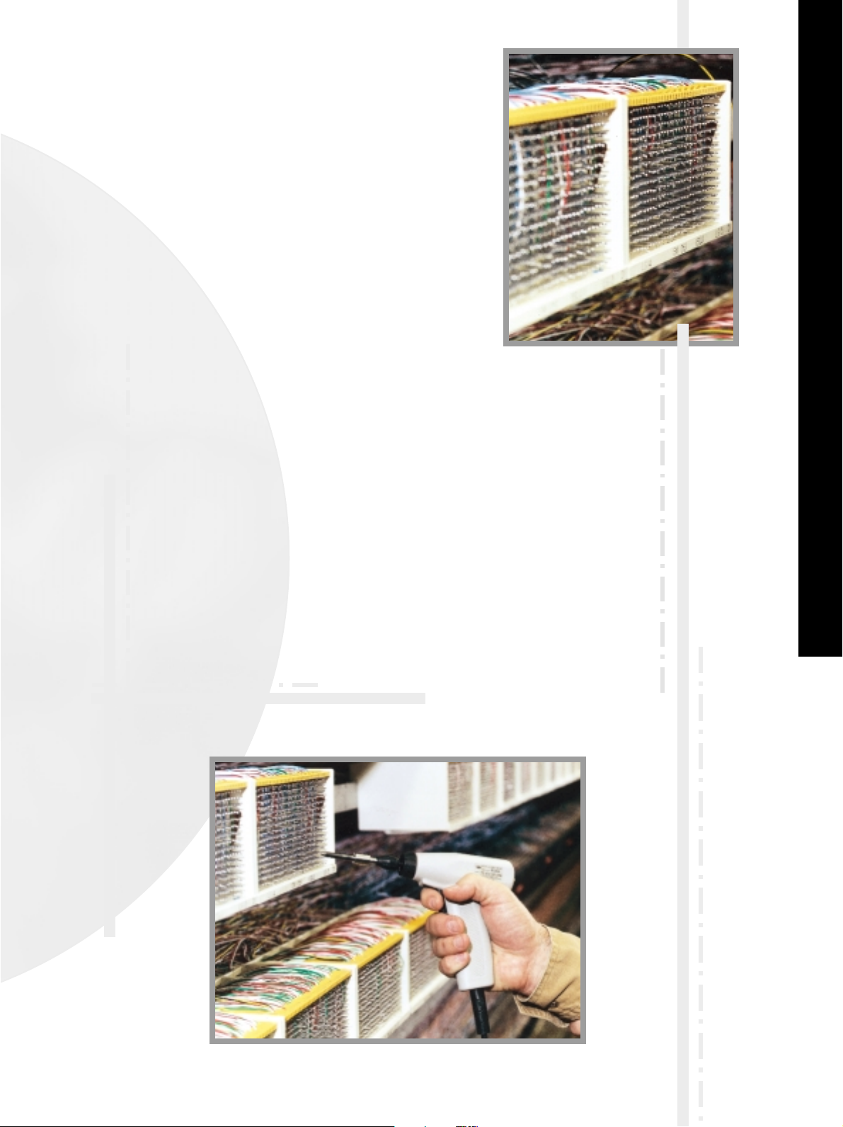
TELECOMMUNICATIONS INTERCONNECTION
3
E
NHANCING
NETWORK
RELIABILITY
WITH
OK I
NDUSTRIES
Founded in 1946, OK Industries is a major force in
the telecommunications and electronics
industries and is a division of a large diversified
multinational corporation. We are a global
supplier of hand tools for the interconnection of
communications networks. Our dependable
products employ precision technologies for the
preparation and connection of copper and Fibre
optic cables in applications including public and
enterprise voice and data communications. Ask
for OK Industries when you wish to build
reliability into your networks.
Page 4
FIBRE OPTIC CABLE
STRIPPING TOOLS
For installers and technicians working with fibre optic cable, OK Industries offers the patented Micro-Strip
®
Series
stripping tools. This innovative range of tools allows for quick, easy stripping of jackets, coatings and buffer materials,
yet is designed to preserve the integrity of the glass core. Opposing stripping blades self-align around the fibre to
assure concentric scoring and precision-stripped, nick-free fibre. The tools also include a fibre support channel, which
maintains perpendicularity between the fibre and the blades; this helps to prevent core damage from flexing and
bending. A thermal version is available to facilitate stripping of jackets, ribbon cables and other difficult applications.
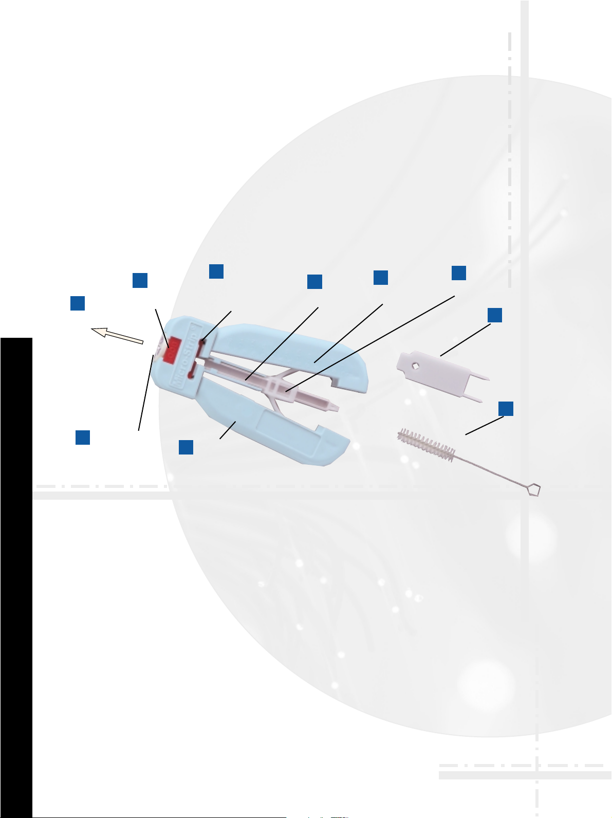
A. Handle
Assembly
B. Fibre Guide
(interchangeable
and replaceable)
C. Stripping
Force
D. Fibre Guide
Lock
E. Cutter Blade Set
(interchangeable
and replaceable)
F. Fibre
Support
Channel
G. Strip
Length
Guide
H. Spring
Assembly
I. Push
Tool
J. Cleaning
Brush
A
B
C
D
E
F
G
H
I
J
NON-THERMAL AND THERMAL STRIPPING TOOL FEATURES
A HANDLE ASSEMBLY
Standard stripping handle
accepts interchangeable
parts quickly and easily.
B FIBRE GUIDE
Selected for each normal
diameter of unstripped
buffer or cable. Wrongsized fibre will not fit,
assuring that fibre is
precisely positioned,
properly stripped, and not
nicked or damaged.
C STRIPPING FORCE
is applied longitudinally
with the fibre. The chance
for harmful drag of
stripped fibre against the
blade is virtually
eliminated, even with
operator inattention or
fatigue.
D FIBRE GUIDE LOCK
holds the fibre guide
securely in position.
Colour-coded to match the
cutter blade set.
E CUTTER BLADE SET
Can be selected for each
FIBRE coating or cladding
diameter. Opposing blades
self-align around fibre
guide to assure concentric
scoring and precision-
stripped, nick-free fibre.
Blades travel in a straight
line to assure proper
alignment. Colour coded to
match the fibre lock.
F FIBRE SUPPORT
CHANNEL
Guides fibre being stripped
(up to 900µm) in straight
line to prevent core
damage from flexing or
bending. For jacket
stripping, cable support
channel performs a similar
function.
G STRIP LENGTH GUIDE
calibrated in 1/16" for
desired strip lengths.
H SPRING ASSEMBLY
keeps handles apart, ready
for next fibre or cable
I PUSH TOOL
(supplied with handle)
makes installation and
removal of cutter blade
sets and fibre locks quick
and easy.
J CLEANING BRUSH
(supplied with handle)
effectively clears small
pieces of residue from the
tool.
FIBRE OPTIC CABLE STRIPPING TOOLS
4
Page 5
5
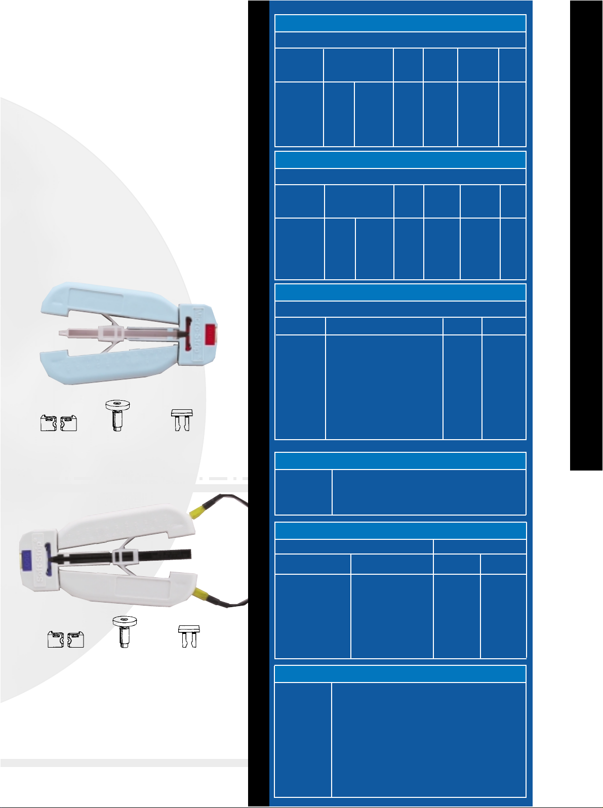
Use these two standard handles to strip
buffered fibre up to 900µm, or jacketed fibre
up to 3.1mm, quickly and easily. Simply select
and install the proper cutter blade sets, fibre
guides and fibre guide locks. Or if you prefer,
purchase Micro-Strip
®
and Soft-Strip®tools
individually fitted for the fibre or jacket
diameter you specify. Cutter blade sets, fibre
guides and fibre guide locks come already
installed.
THERMAL STRIPPING TOOL
COATING/BUFFER STRIPPING TOOL
Cutter Blade set
Fibre Guide
Fibre-Guide Lock
Cutter Blade set
Fibre Guide
Fibre-Guide Lock
◊ For best results use .0063 inch blade when removing a 250µm coating
◊◊ For best results use .0080 inch blade when removing a 900µm buffer.
*Catalogue numbers are for two cutter blade sets packaged together with a
matching Colour-coded fibre lock. Each cutter blade set consists of a pair of joined,
matched blades which must be snapped apart prior to use. Matched cutter blade
sets are NOT interchangeable, and must be used with their matching half.
Catalogue numbers are for a single, individually packaged fibre guide with
integral size indicator disk.
†Includes tool individually boxed with cleaning brush, push tool and instructions.
††Catalogue numbers are for single individually packaged fibre Guide (with
integral size indicator disk).
NON-THERMAL TOOLS
250µm Coating◊
900µm Buffer◊◊
2.5mm Jacket/
900µm Buffer
2.5mm Jacket
3mm Jacket
125-135
125-175
125-140
2.5
3.0
.0049-.0053
.0049-.0068
.0049-.0068
.098
.118
.0063
.008
.054
.054
FS-Ø6S-13
FS-Ø8S-40
FS-Ø8S-B5
FS-54S-D1
FS-54S-D2
FS-B-06S
FS-B-08S
FS-B-08S
FS-B-J54
FS-B-J54
COMPLETE TOOLS AND REPLACEMENT BLADE SETS
Fibre Cladding
Diameter to Expose or
Jacket Dia.
(µm) (in.)
Material
to be
Stripped
Proper
Blade
Diameter
(in.)
Complete
Tool
Catalogue
Number †
Replacement
Cutter Blade
Set Catalogue
Number *
Blade
Colour
Code
Purple
Red
Red
Natural
Natural
THERMAL TOOLS-SINGLE FIBRE
NON-THERMAL KITS
FSK-1
FSK-2
FSK-2A
Kit for 125/140 Cladding; 250/900 Coating; 2.5 & 3.0 mm Jackets
Kit for 125/250 Stripper; 125/900 Stripper; 2.5 or 3.0 mm Jacket
Stripper; Kevlar Scissor
Kit for 125/900 Buffer, 2.5MM jacket, scissors
OTHER ACCESSORIES
FSH
FSKS
FS-CB-1
FS-PT-1
FSCR-60-SW
FST-A-T3
FST-A-T4
FST-A-T5
FST-A-T6
FST-RHM-1
FST-RHM-2
Coating/Buffer Stripper Handle
Kevlar Scissors
Blade Cleaning Brush
Blade & Guide Assembly Tool
FIBRE Optic Sapphire Wedge Scribe
U.S. AC Adapter (Thermal Stripper only)
U.K. AC Adapter (Thermal Stripper only)
Euro AC Adapter (Thermal Stripper only)
Australian AC Adapter (Thermal Stripper only)
Heater Cartridge (FST-4B only)
Heater Cartridge (FST-4T only)
FIBRE GUIDES
≤250
250-343
407-457
457-533
533-635
635-787
787-889
889-1016
2.5
3.0
FS-G-26MM
FS-G-31MM
FS-G-10
FS-G-13
FS-G-18
FS-G-21
FS-G-25
FS-G-31
FS-G-35
FS-G-40
Jacket
Diameter (µm)
Catalogue
Number ††
Fibre Coating or Buffer
Dia. to Strip (µm)
Replacement Fibre
Guide Cat. No ††
THERMAL TOOLS-RIBBON FIBRE*
FSTR-3B-06-G1
FSTR-3B-06-G2
FSTR-3E-06-G3
FSTR-3E-06-G4
FSTR-3B-06-G5
FSTR-3B-06-G6
FSTR-3B-06-G8
FSTR-3B-06-G10
FSTR-3E-06-G15
12- Fibre AT&T ASR Thermal Ribbon Stripper
12- Fibre Bonded/Ribbonised Stripper
4 Fibre Encapsulated Thermal Stripper
8 Fibre Encapsulated Thermal Stripper
4 Fibre Bonded Thermal Stripper
8 Fibre Bonded Thermal Stripper
10 Fibre Bonded Thermal Stripper
6 Fibre Bonded Thermal Stripper
12 Fibre Encapsulated Thermal Stripper
FS-RB-06
FS-RB-06
FS-RB-06
FS-RB-06
FS-RB-06
FS-RB-06
FS-RB-06
FS-RB-06
FS-RB-06
FS-G-RG1
FS-G-RG2
FS-G-RG3
FS-G-RG4
FS-G-RG5
FS-G-RG6
FS-G-RG8
FS-G-RG10
FS-G-RG15
COMPLETE TOOLS AND REPLACEMENT BLADE SETS
Description
Catalogue Number
Replacement
Blade Set
Replacement
Ribbon Guide
COATING OR BUFFER
JACKET
AA BATTERIES
250µm Coating◊
900µm Buffer◊◊
AC ADAPTER
250µm Coating◊
900µm Buffer◊◊
125-135
125-175
125-135
125-175
.0049-.0053
.0049-.0068
.0049-.0053
.0049-.0068
.0063
.008
.0063
.008
FST-4B-06S-13
FST-4B-08S-40
FST-4T-06S-13
FST-4T-08S-40
FS-B-06S
FS-B-08S
FS-B-06S
FS-B-08S
COMPLETE TOOLS AND REPLACEMENT BLADE SETS
Fibre Cladding
Diameter to Expose or
Jacket Dia.
(µm) (in.)
Material
to be
Stripped
Proper
Blade
Diameter
(in.)
Complete
Too l
Catalogue
Number †
Replacement
Cutter Blade
Set Catalogue
Number *
Blade
Colour
Code
Purple
Red
Purple
Red
MICRO-STRIP ORDERING INFORMATION
* The Ribbon Fibre tools are all Electric Powered
Page 6

NON THERMAL STRIPPING TOOL
6
STRIPPING PROCEDURE
(BUFFERED OPTICAL FIBRE TOOL)
Hold tool in one hand, fibre in the other. Keep handles in fully expandable
position. Insert fibre through fibre guide until end aligns with rule markings
to match desired strip length (1).
Squeeze handles closed. Cutter blades are now scoring the buffer or
coating (2).
While maintaining a slight pressure to keep cutter closed, withdraw fibre
from tool, completing the stripping process (3).
STRIPPING PROCEDURE
(JACKETED FIBRE TOOL WITH LATCH BAR)
Insert cable through fibre guide. Align end of cable with rule marking
at desired strip length (1).
Close handles together so blades cut into jacket (2).
While holding handles closed, flip latch bar down around pin. Release
handles to latched, semi-open position. Do not reclose handles. Move hand
up to grasp head of tool. While other hand is holding cable firmly, pull with
a quick, smooth motion. Flip latch off pin. Stripped jacket will fall out
through rear of channel when handles are fully opened.Note: Never leave
tool with latch bar in locked position. This can cause Delrin spring to take a
set, preventing handles from opening fully. When stripping hard, tough or
thick jackets, it is not necessary to use latch bar. Lock bar out of the way by
tightening the screw.
Close handles. Blade sets cut almost
through the buffer or jacket without
ever touching the fibre.
With handles closed, pull fibre or cable
from tool. Always a precision strip
length. fibre is never nicked or damaged.
NON-THERMAL STRIPPING
JACKET AND COATING
2
3
PROPER TOOL SELECTION
Select the proper tool and components for either fibre stripping or jacket stripping by referring to the tables on the
back page. If necessary, install proper fibre guide, fibre guide lock and cutter blade set.
Insert correct fibre through guide and
into support channel to desired strip
length.
1
P ATENTED, SELF- CENTERING MICRO-STRIP
®
STRIPPING SYSTEM ASSURES
PRECISE, CONCENTRIC SCORING, WITHOUT CLADDING OR CORE DAMAGE.
SNAP-APART PRECISION-MACHINED BLADE HALVES
MOLDED INTO THERMOPLASTIC BODIES.
C
Fibre is withdrawn,
assuring a perfect
strip every time.
Only the coating or
buffer is scored.
fibre is never nicked
or damaged.
Fibre enters guide
through opening
dimensioned for a
particular diameter
range. Fibre that is
too large won’t
enter the guide;
fibre that’s too
small won’t be
stripped.
B As gripping handles close,
each blade half moves in a
straight line to self-align
around the fibre guide. This
places the blades in perfect
concentric relationship.
End of fibre
guide supports
blades during
stripping to
prevent blade
flexing
and
fatigue.
A
C
B
CAUTION
Always wear approved eye
protection when working
with any type of fibre optic
cable or wire.
A
Page 7

THERMAL STRIPPING TOOL
7
NOTE: Blades are Colour coded and matched to diameter and Colour of fibre guide lock. Replace
or install fibre guide and guide lock as needed. Always test-strip fibre or cable after installing new
blade set. Remove blades periodically and clean with brush provided and alcohol.
CAUTION: Heater units continuously when handles are closed. Do not hold handles closed for
longer than 20 seconds for AA and D-Size battery units, 10 seconds for 6-Volt battery/
AC adapter units, or overheating can damage tool. Do not touch heater oven while in operation.
Allow oven to cool before removal and cleaning.
Insert fibre through fibre guide and into
heater oven to desired length. Be sure
buffered fibre is flat in the oven channel.
Always allow at least 1/8" gap from fibre
tip to end of oven channel. Otherwise
heater oven movement will cause fibre
to buckle up and out of heating zone.
Close handles all the way. Blades are
precisely aligned for concentric scoring
without cladding, core or conductor
damage. Heater oven is automatically
activated to start the softening process.
Keep handles closed (AA or D-size 10-20
sec., 6V or AC adapter 4-8 sec.) for
optimum softening. Then begin to pull
the fibre, slowly increasing pull force
until coating releases from the fibre.
Remove the fibre from the tool with a
smooth, even motion.
1
2
3
Recess
marks
this
side
Replacement
Blades
Fibre
Guide
Lock
Blade
Removal
End
PUSH OUT
BACK SIDE
Fibre
Guide
Fibre
Guide
Lock
Removal
End
PUSH
TOOL
GENERAL
Strip outer jacket (if any), using Soft-Strip®non-thermal tool. Install and
connect battery(s), or install and connect AC adapter. Install proper cutter
blade set, fibre guide and fibre guide lock.
HEATER OVEN
Unit is activated when handles are closed. Close handles only when stripping.
Check heater operation by closing handles firmly for no longer than 10
seconds. Nose end of heater should be warm to the touch.
After stripping operation, remove heater oven from tool and clean with the
brush provided (spring assembly in later models includes automatic scrap
ejector.) Reinsert, making sure that heater oven is pushed completely
forward toward the blade area and snaps into place. 2" heater oven area
should be visible at front of tool so operator can monitor positioning and
preheating of coating.
CUTTER BLADE REPLACEMENT INSTRUCTION PROCEDURE FOR
NON-THERMAL AND THERMAL SOFT-STRIP
®
STRIPPING TOOLS
TO REMOVE INSTALLED BLADES:
1. Using flat end of push tool, remove fibre guide lock by pushing out from
back side of tool head.
2. Remove fibre guide from tool.
3. Using prong end of push tool in small holes on back side of tool head,
eject blade set.
IMPORTANT Do not remove cutter blades while fibre guide is still in tool.
TO INSTALL NEW BLADES:
(Furnished in a matched set for blade position.
Snap apar
t before installation.)
1. Install with “ears” pointing toward top of tool and recess marks visible.
Push firmly with flat end of push tool until both blades are seated.
2. Insert fibre guide through hole in top of tool until it stops.
3. Insert fibre guide lock through slot in front of tool head.
THERMAL
STRIPPING
Page 8

WIRE WRAPPING OVERVIEW
8
By bending the wire around the sharp corner
of the terminal, the oxide layer on both wire
and terminal is crushed or sheared, and a clean,
oxide-free metal-to-metal contact is obtained.
A “Regular” bit wraps the bare wirearound the terminal.
A “Modified” bit wraps a portion of insulation around
the terminal in addition to the bare wire.This
greatly increases the ability to withstand vibration.
Regular
Modified
In. .010 .015 .020 .025 .030 .035 .040 .045 .050 .055 .060 .065 .070 .075 .080 .085 .090 .095 .100
mm 0.25 0.38 0.51 0.64 0.76 0.89 1.02 1.14 1.27 1.40 1.52 1.65 1.78 1.91 2.03 2.16 2.29 2.41 2.54
.010 .014 .018 .022 .027 .032 .036 .041 .046 .051 .056 .061 .066 .071 .076 .081 .086 .091 .096 .101
0.25 0.36 0.46 0.56 0.69 0.81 0.91 1.04 1.17 1.30 1.42 1.55 1.68 1.80 1.93 2.06 2.18 2.31 2.44 2.57
.015 .018 .021 .025 .029 .033 .038 .043 .047 .052 .057 .062 .067 .072 .077 .082 .087 .092 .097 .102
0.38 0.46 0.53 0.64 0.74 0.84 0.97 1.09 1.19 1.32 1.45 1.58 1.70 1.83 1.96 2.08 2.21 2.34 2.46 2.59
.020 .022 .025 .028 .032 .036 .040 .045 .049 .053 .058 .063 .068 .073 .078 .083 .088 .093 .098 .103
0.51 0.56 0.64 0.71 0.81 0.91 1.02 1.14 1.25 1.35 1.47 1.60 1.73 1.85 1.98 2.11 2.24 2.36 2.49 2.62
.025 .027 .029 .032 .035 .039 .043 .047 .050 .056 .060 .065 .069 .074 .079 .084 .089 .094 .099 .104
0.64 0.69 0.74 0.81 0.89 0.99 1.09 1.19 1.27 1.42 1.52 1.65 1.75 1.88 2.01 2.13 2.26 2.39 2.52 2.64
.030 .032 .033 .036 .039 .042 .046 .050 .054 .058 .062 .067 .071 .076 .080 .085 .090 .095 .100 .105
0.76 0.81 0.84 0.91 0.99 1.07 1.17 1.27 1.37 1.47 1.58 1.70 1.80 1.93 2.03 2.16 2.29 2.41 2.54 2.67
.035 .036 .038 .040 .043 .046 .049 .052 .056 .060 .064 .069 .073 .078 .082 .087 .091 .096 .101 .106
0.89 0.91 0.97 1.02 1.09 1.17 1.25 1.32 1.42 1.52 1.63 1.75 1.85 1.98 2.08 2.21 2.31 2.44 2.57 2.69
.040 .041 .043 .045 .047 .050 .052 .056 .060 .064 .068 .072 .076 .080 .084 .089 .092 .097 .102 .107
1.02 1.04 1.09 1.14 1.19 1.27 1.32 1.42 1.52 1.63 1.73 1.83 1.93 2.03 2.13 2.26 2.34 2.46 2.59 2.72
.045 .046 .047 .049 .050 .054 .056 .060 .063 .067 .071 .074 .078 .083 .087 .091 .096 .101 .105 .109
1.14 1.17 1.19 1.25 1.27 1.37 1.42 1.52 1.60 1.70 1.80 1.88 1.98 2.11 2.21 2.31 2.44 2.57 2.67 2.77
.050 .051 .052 .053 .056 .058 .060 .064 .067 .071 .074 .078 .082 .086 .090 .094 .098 .103 .107 .111
1.27 1.30 1.32 1.35 1.42 1.47 1.52 1.63 1.70 1.80 1.88 1.98 2.08 2.18 2.29 2.39 2.49 2.62 2.72 2.82
Example: If “E”=.020”. “F”=.060”. The terminal diagonal is .063" as shown on chart.
Step 1: Bit, Sleeve and
Pre-Stripped Wire
Step 2: Wire Insertion
Step 3: Wire Anchoring
Step 4: Terminal
Insertion
Step 5: Finished
Connection
METAL- TO- METAL CONTACT
TYPES OF WRAP
TERMINAL DIAGONAL CHART
HOW TO MAKE WIRE
WRAPPED CONNECTIONS
Wire Size Min. number Min. strip
AWG Dia. Dia. of turns force
inches mm (Bare Wire) lbs. gms
16 .051 1.30 4 15 6800
18 .0403 1.00 4 15 6800
20 .032 0.80 5 8 3600
22 .0253 0.65 5 8 3600
24 .0201 0.50 6 7 3200
26 .0159 0.40 7 6 2700
28 .0126 0.32 7 5 2200
30 .0100 0.25 7 3.3 1500
*Conforms to MIL-STD-1130B
STRIP FORCE CHART
SOME HINTS ON MAKING WRAPPED CONNECTIONS
OPEN WRAP & SPIRAL WRAP
Just keep the OK tool on the
terminal until the wrap is
complete. Early removal can
result in spiral and open wraps.
PIGTAIL
Wire wrapping is a precision
technique and the wrong bit
and sleeve just cannot do the
job. Improper selection can
cause problems ranging from
“Pigtails” to loose wraps.
Wire Wrapping is a method of making a wire connection by coiling the bare wire around the sharp corners of a
terminal under mechanical tension. The technology was developed as an alternative to soldering, which presents
various safety and reliability problems in many applications. A principal advantage of wire wrapping is that it
provides a high-reliability connection that is also easily removed to correct or modify a wiring layout. Wire wrapping
subjects the wire to tremendous tension and compression forces, causing the oxide layer on both wire and terminal
to be crushed or sheared, resulting in a clean, oxide-free metal-to-metal contact. A standard wrap is generally used
for 24 AWG and larger diameter wires; a modified wrap is typically used for 24 AWG and smaller wires, and is used
almost exclusively for 28 to 30 AWG wires. In either case, the wrap style affects only the connection’s mechanical
stability; both styles provide suitable electrical connections.
WIRE WRAPPING OVERVIEW
INSUFFICIENT TURNS
It’s easy to feed wire into the
slot in the OK bit correctly. Be
sure the stripped end of the
wire is “pushed-in” all the way.
OVERWRAP
Do not press too hard. Let the
OK tools do the work. Excessive
pressure can lead to
overwrapping. Backforce "BF"
to prevent overwrapping is
available on most power tools
and is recommended for use
with 26 through 30 AWG wire.
Page 9

PTX SERIES ERGONOMIC WIRE WRAPPING TOOLS
PTX SERIES
ERGONOMIC WIRE WRAPPING TOOLS
Part No. Description Weight Voltage RPM
PTX Battery Wrap/Unwrap Tool (Battery not included) 1.2 lb. 3.6V* 3700
PTX-1 Electric Wrap/Unwrap Tool - 115V 0.86 lb. 115V 3700
PTX-1BF Electric Wrap/Unwrap Tool w/Backforce - 115V 0.86 lb. 115V 3700
PTX-2 Electric Wrap/Unwrap Tool - 230V 1.0 lb. 230V 4200
PTX-2-UK Electric Wrap/Unwrap Tool - UK Plug - 230V 1.0 lb. 230V 4200
PTX-2BF Electric Wrap/Unwrap Tool w/Backforce - 230V 1.0 lb. 230V 4200
PTX-2BF-UK Electric Wrap/Unwrap Tool w/Backforce - UK Plug - 230V 1.0 lb. 230V 4200
PTX-KIT1 115V battery tool kit (tool, charger, (2) batteries)
PTX-KIT2 230V battery tool kit (tool, charger, (2) batteries)
PTX-KIT2-UK 230V battery tool kit w/ UK Plug (tool, charger, (2) batteries)
* Powered by long-life NiMH battery
The PTX Series Wire Wrapping Tools from OK Industries
bring revolutionary new benefits to installers, telecom
technicians and other users. With worker safety in
mind, we consulted a certified ergonomist and
created an ergonomic tool, which includes a
lightweight, well-balanced construction, dual-finger
short-throw trigger, and a long handle to mitigate
pressure on the palm. These features help to prevent
repetitive stresses and result in an industry-leading design
from a comfort and safety standpoint. Ask for the PTX Series
Wire Wrapping Tools from OK Industries — and arm your
workers with the tools that offer efficiency and worker
safety in your interconnect activity.
PTX-BC1
PTX-B
KEY FEATURES
ACCESSORIES
■ PTX-B PTX Battery, 3.6V
■ PTX-BC1 115V Charger for
PTX-B battery
■ PTX-BC2 230V Charger for
PTX-B battery
■ PTX-BC2-UK 230V Charger with
UK Plug for
PTX-B battery
9
Low Battery Indicator
High Power Motor
Reverses for
Unwrapping
Permanently
Attached
Collet Nut
Ergonomic,
Rugged
Tool Design
■ Ergonomic Design — Minimises Repetitive Stress
■ Rugged Construction for Field Usage
■ Battery and Electric Powered Versions Available
■ Wraps and Unwraps 20 to 30 AWG Wire
■ Rated Maximum Usage: 2,500 cycles/day
■ For Bits & Sleeves: see Page 11
Page 10

MANUAL WIRE WRAPPING TOOLS & KITS
10
The G100/R3278 and G200/R3278 tools are designed
with a chuck nose piece to make use of the full line of
bits and sleeves made for power tools. The
G100/R3278INS is coated with an insulative material,
providing 1000V of dielectric strength across most of
the housing, to help ensure worker and system safety.
These tools accommodate wire sizes from 22 AWG
(0.65mm) thru 32 AWG (0.20mm).
The combination of the G100/R3394 unwrap tool
and the SU unwrap bits gives you the best tool for
high speed wire unwrapping. High production, long
life, low maintenance. Use Unwrap Set SU2026 for
wire AWG 20 thru 26 (0.80 thru 0.40mm) and Set
SU2832 for wire AWG 26 thru 32 (0.40 thru 0.20mm).
Unwrap Bit Unwrap Sleeve Bit and Sleeve Wire Size Terminal Hole Diameter
Part No. Part No. Set No. AWG mm Inches mm
2026UB 2032 SU2026 22-26 0.65-0.40 .070 1.77
2832UB 2032 SU2832 26-32 0.40-0.20 .036 0.96
G100/R3394
G100/R3278 Aluminum
This is a complete kit for technicians working at a Main
Distributing Frame. The G200/R3278 Manual Gun
produces wire wrapped connections merely by
squeezing the trigger, and works with any bit and
sleeve. The versatile HW-UW-224 Hand Wrap-Unwrap
Tool (22-24 AWG) does the work of two tools in one wrapping and unwrapping - just by changing the cap
from one end to the other. The ST-100 22-24 AWG wire
Cut-and-Strip Tool offers easy, clean stripping of up to
four wires with 15/16" - 19/16" adjustable strip off
length. This kit comes complete with KB224 22-24 AWG
bit, P2224 22-24 AWG sleeve and H-1000 cordura tool
pouch.
WWK-1
G100/R3394 Bits & Sleeves:
MANUAL WIRE WRAPPING
TOOLS & KITS
■
G200/R3278 :
Lexan™
■
G200/R3278-K :
Speed Wrap Tool kit
■
G100/R3278 :
Aluminum
■ G100/R3278INS :
Aluminum (insulated)
■
For Bits & Sleeves :
see page 11
■
WWK-1 : Telecom Wire Wrap Kit
■
G100/R3394 :
Manual Wire Unwrapping Tool
MANUAL WIRE WRAPPING TOOLS
MANUAL WIRE UNWRAPPING TOOL
G200/R3278 Lexan™
G100/R3278INS
(Shown with Bit/Sleeve)
TELECOM WIRE WRAP KIT
Page 11

WIRE WRAPPING BITS AND SLEEVES
11
BITS AND SLEEVES CHART ( AWG) INCHES
BITS AND SLEEVES CHART MILLIMETRES
Maximum Minimum Maximum Terminal Terminal
Wire Bit Sleeve Insulation Terminal Terminal Hole Effective Hole
Gauge Regular Modified Part No. Part No. Diameter Diagonal Diagonal Depth Radius Diameter
mm mm mm mm mm mm mm
1.00
●
KB18 P194 – 1.52 1.85 25.40 3.81 1.90
0.80
●
WB20M P194LN 1.50 1.07 1.85 25.40 3.81 1.90
0.65-0.80
●
KB2075 P2224 – 1.07 1.85 25.40 3.12 1.90
0.65
●
KB22LT P2224 – 1.54 2.15 25.40 3.17 2.18
0.65
●
KB22 P2224 – 1.37 1.85 19.05 2.97 1.90
0.65
●
WB2275M P2224 1.32 1.24 1.87 25.40 3.35 1.90
0.50-0.65
●
KB224LH P2224 – 1.54 2.15 25.40 2.97 2.18
0.50-0.65
●
KB224-1 P2224 – 1.37 1.85 25.40 2.82 1.90
0.50-0.65
●
KB224 P2224 – 1.37 1.85 20.50 2.82 1.90
0.50-0.65
●
WB224M P2224 1.27 1.24 1.87 31.75 3.07 1.90
0.50
●
*KB2444 P3032LN – 0.60 1.09 25.40 2.10 1.11
0.50
●
WB24DH P2224 1.17 1.37 1.85 44.50 2.97 1.90
0.50
●
KB24 P2426 – 1.39 1.87 19.05 2.54 1.90
0.50
●
*WB24SM P3032LN 1.11 0.60 1.09 19.05 2.48 1.11
0.50
●
WB24DHM P2224 1.27 1.24 1.72 28.50 2.99 1.75
0.40-0.50
●
WB2426M P2224 1.17 1.37 1.85 19.05 2.99 1.90
0.40-0.50
●
KB2466 OK8519 – 1.37 1.65 25.40 2.48 1.67
0.40
●
*KB2639 P26LN – 0.58 0.96 19.05 1.72 1.02
0.40
●
KB26 P2426 – 1.47 1.85 25.40 2.54 1.90
0.40
●
*WB26SM P26LN 0.79 0.58 0.96 19.05 1.90 1.02
0.40
●
WB26M P2224 1.17 1.37 1.85 25.40 2.99 1.90
0.40
●
*WB2644M P3032LN 1.17 0.60 1.09 19.05 2.48 1.11
0.40
●
WB2669M P2426 1.04 1.34 1.72 25.40 2.77 1.75
0.32
●
*WB28SHM P3032 0.76 0.79 0.89 19.05 1.67 0.91
0.29-0.32
●
*WB2829M P3032L 0.91 0.83 0.96 19.05 2.31 1.02
0.25
●
*SB30MSH-B P3032 0.69 0.79 0.89 19.05 1.62 0.91
0.25
●
*SB30MMK P3032 0.58 0.79 0.89 19.05 1.62 0.91
0.20-0.25
●
*WB3032M P3032 0.69 0.86 0.96 19.05 1.62 1.02
* These tools are recommended for 0.63mm terminals on 2.54mm centres
WIRE WRAPPING BITS & SLEEVES
Maximum Minimum Maximum Terminal Terminal
Wire Bit Sleeve Insulation Terminal Terminal Hole Effective Hole
Gauge Regular Modified Part No. Part No. Diameter Diagonal Diagonal Depth Radius Diameter
(AWG) Inches Inches Inches Inches Inches Inches
18
●
KB18 P194 – .060 .073 1.00 .150 .075
20
●
WB20M P194LN .059 .042 .073 1.000 .150 .075
20-22
●
KB2075 P2224 – .042 .073 1.000 .123 .075
22
●
KB22LT P2224 – .061 .085 1.000 .125 .086
22
●
KB22 P2224 – .054 .073 .750 .117 .075
22
●
WB2275M P2224 .052 .049 .074 1.000 .132 .075
22-24
●
KB224LH P2224 – .061 .085 1.000 .117 .086
22-24
●
KB224-1 P2224 – .054 .073 1.000 .111 .075
22-24
●
KB224 P2224 – .054 .073 .807 .111 .075
22-24
●
WB224M P2224 .050 .049 .074 1.250 .121 .075
24
●
*KB2444 P3032LN – .024 .043 1.000 .083 .044
24
●
WB24DH P2224 .046 .054 .073 1.750 .117 .075
24
●
KB24 P2426 – .055 .074 .750 .100 .075
24
●
*WB24SM P3032LN .044 .024 .043 .750 .098 .044
24
●
WB24DHM P2224 .050 .049 .068 1.125 .118 .069
24-26
●
WB2426M P2224 .046 .054 .073 .750 .118 .075
24-26
●
KB2466 OK8519 – .054 .065 1.000 .098 .066
26
●
*KB2639 P26LN – .023 .038 .750 .068 .040
26
●
KB26 P2426 – .058 .073 1.000 .100 .075
26
●
*WB26SM P26LN .031 .023 .038 .750 .075 .040
26
●
WB26M P2224 .046 .054 .073 1.000 .118 .075
26
●
*WB2644M P3032LN .046 .024 .043 .750 .098 .044
26
●
WB2669M P2426 .041 .053 .068 1.000 .109 .069
28
●
WB2870M P2426 .034 .053 .068 1.000 .103 .070
28-29
●
*WB2829M P3032L .036 .033 .038 .750 .091 .040
30
●
*SB30MSH-B P3032 .027 .031 .035 .750 .064 .036
30
●
*SB30MMK P3032 .023 .031 .035 .750 .064 .036
30-32
●
*WB3032M P3032 .027 .034 .038 .750 .064 .040
*These tools are recommended for .025" square terminals on .100 centres
Fully compatible with any make or model wire wrapping tool,
except G100 and G200 manual tools, which are obsolete and
require special bits and sleeves.
Page 12

specialised BITS AND SLEEVES
12
Precision devices which attach easily to your wire wrapping
tool for applications requiring extra “reach”. Simply install
the extension into the tool, then install the bit and sleeve
into the extension. Fits all Electric and Manual wire
wrapping tools. Compatible with all bits and sleeves made
for Power Wire Wrapping Tools.
The insulated sleeves are covered with a material which
provides 1000V dielectric strength which helps to prevent
shorting between pins and enhances worker safety.
P2426-5
KB24-5
Maximum Minimum Maximum Terminal Terminal
Bit Sleeve Wire Size Regular Modified Insulation Terminal Terminal Hole Effective Hole
Part No. Part No. Diameter Diagonal Diagonal Depth Radius Diameter
AWG mm In. mm In. mm In. mm In. mm In. mm In. mm
KB22-5 P2224-5 22 0.65
●
– – .054 1.37 .073 1.85 .750 19.05 .117 2.97 .075 1.90
KB24-5 P2426-5 24 0.50
●
– – .055 1.39 .073 1.85 .750 19.05 .100 2.54 .075 1.90
KB26-5 P2426-5 26 0.40
●
– – .058 1.47 .073 1.85 .750 19.05 .100 2.54 .075 1.90
SPECIALISED BITS & SLEEVES
POWER UNWRAPPING BITS & SLEEVES
WIRE WRAPPING EXTENSION ATTACHMENTS
BITS AND INSULATED SLEEVES
2” (5CM)
LONGER THAN STANDARD BITS& SLEEVES
Unwrap Unwrap Bit and Wire Size Terminal
Bit Sleeve Sleeve Hole Dia.
Part No. Part No. Set AWG mm In. mm
2026UB SOK-2230 PUW-2226 20-26 0.80-0.40 .070 1.77
2832UB SOK-2230 PUW2830 26-32 0.40-0.20 .038 0.96
Maximum Minimum Maximum Terminal Terminal
Bit Sleeve Wire Size Regular Modified Insulation Terminal Terminal Hole Effective Hole
Part No. Part No. Diameter Diagonal Diagonal Depth Radius Diameter
AWG mm In. mm In. mm In. mm In. mm In. mm In. mm
KB22 P2224INS 22 0.65
●
– – .054 1.37 .073 1.85 .750 19.05 .117 2.97 .075 1.90
KB224 P2224INS 22-24 0.50-0.65
●
– – .054 1.37 .073 1.85 .807 20.50 .111 2.82 .075 1.90
KB24 P2426INS 26 0.50
●
– – .055 1.39 .074 1.87 .750 19.05 .100 2.54 .075 1.90
KB26 P2426INS 26 0.40
●
– – .058 1.47 .073 1.85 1.0 25.40 .100 2.54 .075 1.90
Maximum Minimum Maximum Terminal Terminal
Bit Sleeve Wire Size Regular Modified Insulation Terminal Terminal Hole Effective Hole
Part No. Part No. Diameter Diagonal Diagonal Depth Radius Diameter
AWG mm In. mm In. mm In. mm In. mm In. mm In. mm
KB22-5 P2224-5INS 22 0.65
●
– – .054 1.37 .073 1.85 .750 19.05 .117 2.97 .075 1.90
KB24-5 P2426-5INS 24 0.50
●
– – .055 1.39 .073 1.85 .750 19.05 .100 2.54 .075 1.90
KB26-5 P2426-5INS 26 0.40
●
– – .058 1.47 .073 1.85 .750 19.05 .100 2.54 .075 1.90
■
EXT-400 :
4.0’’ (100mm) extension
These bits and sleeves are designed for wire wrapping in
areas requiring deep penetration. Their 5" (127mm)
length ensures “true” connections in hard-to-get-at
locations.
P2426-5INS
KB24-5
EXTENDED LENGTH (5”) BITS AND INSULATED SLEEVES
For PTX Series battery or electric wrap/unwrap tool.
Page 13

Min. Terminal Max. Terminal Terminal Terminal Hole Effective
Part # Description Wire Size Diagonal Diagonal Hole Depth Diameter Radius
mm AWG mm in. mm in. mm in. mm in. mm in.
DFB224 Dual Function Wrap/Unwrap .50/.65 22/24 1.37 .054 1.85 .073 25.04 1.00 1.90 .075 2.82 .111
Bit/Sleeve Set, 22/24 AWG
DFB2426 Dual Wrap/Unwrap bit & .40/.50 24/26 1.37 .054 1.85 .073 25.04 1.00 1.67 .066 2.48 .098
sleeve set, 24-26 AWG
The Wrap/Unwrap bit is shipped with the sleeve set in the wrap position.
To change to the unwrap simply pull the sleeve out
approximately 1/4” (the sleeve is spring loaded and you should feel some tension while pulling forward), rotate the sleeve in either
direction 180
0
and release. The sleeve should now be seated approximately 1/4” lower than in the wrap position. This will expose
the unwrap feature on the bit.
To change back to the wrap position pull the sleeve out approximately 1/2” and rotate the sleeve in either direction 180
0
and release
The spout should be in the 12:00 position and the sleeve should be locked in position.
Note: If you cannot rotate the sleeve, you need to pull the sleeve out further before trying to rotate the sleeve.
OK INDUSTRIES INTRODUCES THE DFB224 DUAL FUNCTION BIT
HOW TO USE THE DFB224
DFB224 DUAL FUNCTION
WRAP/UNWRAP BIT
& SLEEVE SET
This innovative product represents a truly revolutionary approach to wire wrapping, by combining both the wrap and the
unwrap functions into one bit/sleeve set. The bit is precision machined for high quality wrapping in the clockwise direction,
but also includes the removal mechanism that is used to unwrap when operated counterclockwise. The user can quickly and
easily switch back and forth between wrap and unwrap mode by retracting or extending the retractable sleeve, and flipping
the switch on a wrap/unwrap power tool (i.e., a power wire wrapping tool with reversible motor). This product, which can
wrap or unwrap 22 and 24 AWG wire, enables the user to maximize operating efficiency while eliminating the need to
purchase and carry extra tools or bits for unwrapping. Also, to prevent pin-to-pin shorting, the retractable sleeve is coated
with a durable 1000V dielectric material.
13
DFB224 DUAL FUNCTION WRAP/UNWRAP BIT & SLEEVE SET
KB-DF224 (wrap/unwrap bit)
P-DF2224 (wrap/unwrap sleeve assembly)
KB-DF2426 (replacement bit for DFB2426)
P-DF2426 (replacementSleeve Assy, DFB2426)
Page 14

HAND WRAPPING AND UNWRAPPING TOOL
14
Wire Size Max. Insulation Terminal Hole Terminal Hole Outside
Part No. Reg. Mod. Type Diameter Diameter Depth Diameter
AWG mm Inches mm Inches mm Inches mm Inches mm
HW-224
●
A 22-24 0.65-0.50 – – .075 1.90 .807 20.50 .218 5.53
HW-224LH
●
A 22-24 0.65-0.50 – – .086 2.18 1.000 25.40 .218 5.53
HW-24DHM
●
A 24 0.50 .050 1.27 .069 1.75 1.125 28.50 .218 5.53
HW-2426
●
A 24-26 0.50-0.40 – – .075 1.90 .750 19.05 .218 5.53
HW-26
●
A 26 0.40 – – .075 1.90 1.000 25.40 .218 5.53
*HW-26SM
●
A 26 0.40 .031 0.79 .040 1.02 .750 19.05 .125 3.17
*HW-30
●
B 30 0.25 .027 0.69 .036 0.91 .750 19.05 .125 3.17
*These tools are recommended for .025" (0.63mm) square terminals on .100" (2.54mm) centres
Note: HW-22 and HW-24 have been replaced by HW-224.
These tools are used to remove wire connections
using 18 thru 32 gauge wire.
Type of Terminal Terminal Outside
Part No. Type Wire Size Unwrap Hole Diameter Hole Depth Diameter
AWG mm Inches mm Inches mm Inches mm
UW1 A 20-26 0.80-0.40 Left Hand .070 1.77 1.000 25.40 .156 3.96
UW2 E 20-26 0.80-0.40 Left and Right Hand .070 1.77 1.000 25.40 .156 3.96
UW4 D 20-26 0.80-0.40 Left Hand .070 1.77 2.360 60.00 .187 4.74
UW5 D 20-26 0.80-0.40 Left and Right Hand .070 1.77 2.360 60.00 .187 4.74
UWD93-93 E 24-32 0.50-0.20 Left and Right Hand .038 0.96 1.000 25.40 .093 2.36
UW2832C D 28-32 0.32-0.20 Left and Right Hand .038 0.96 .750 19.05 .156 3.96
Type “A”
Type “E”
Max. Terminal Terminal
Part Wire Size Insulation Hole Hole Outside Wire Size
Number Reg Mod Diameter Diameter Depth Diameter
AWG mm In. mm In. mm In. mm In. mm AWG mm
HW-UW-224
●
22-24
0.50
– – .075 1.90 .807 20.50 .218 5.53 20-26
0.80
0.65 0.40
HW-UW-224-1
●
22-24
0.50
– – .075 1.90 1.000 25.40 .218 5.53 20-26
0.80
0.65 0.40
HW-UW-224LH
●
22-24
0.50
– – .086 2.18 1.000 25.40 .218 5.53 20-26
0.80
0.65 0.40
HW-UW-24DHM
●
24 0.50 .050 1.27 .069 1.75 1.125 28.50 .218 5.53 20-26
0.80
0.40
*HW-UW-24SM
●
24 0.50 .044 1.11 .044 1.11 .750 19.05 .156 3.96 20-26
0.80
0.40
HW-UW-2426
●
24-26
0.40
– – .075 1.90 .750 19.05 .218 5.53 20-26
0.80
0.50 0.40
HW-UW-26
●
26 0.40 – – .075 1.90 1.000 25.40 .218 5.53 20-26
0.80
0.40
*HW-UW-26SM
●
26 0.40 .031 0.79 .040 1.02 .750 19.05 .125 3.17 24-32
0.50
0.20
*These tools are recommended for .025" (0.63mm) square terminals on .100" (2.54mm) centres.
Note: HW-UW-22 and HW-UW-24 have been replaced by HW-UW-224.
Terminal Terminal
Hole Hole Outside
Diameter Depth Diameter
In. mm In. mm In. mm
.
.070 1.77 1.000 25.40 .156 3.96
.070 1.77 1.000 25.40 .156 3.96
.086 2.18 .750 19.05 .156 3.96
.070 1.77 1.000 25.40 .156 3.96
.038 0.96 1.000 25.40 .093 2.36
.070 1.77 1.000 25.40 .156 3.96
.070 1.77 1.000 25.40 .156 3.96
.038 0.96 1.000 25.40 .093 2.36
.
To switch from wire wrapping to unwrapping takes
only seconds - just a quick change of the cap from
one end to the other.
HAND UNWRAPPING TOOLS
HAND WRAPPING AND UNWRAPPING TOOLS
WRAPPING SIDE UNWRAPPING SIDE
HAND WRAPPING AND UNWRAPPING
TOOLS
HAND WRAPPING TOOLS
These Hand Wrapping Tools are carefully designed to
produce perfect wire wrapped connections.
Precision, long-lasting tools for use where occasional
wraps are required or where power wire-wrapping
tools are not practical. Compact and convenient.
Type “D”
Page 15

COPPER WIRE CUT AND STRIP TOOLS
15
A revolutionary concept for easy and clean stripping of wires for wire wrapping, electronic and appliance
applications. Biomechanically designed for maximum efficiency.
Easy to operate... place wire (up to 4) in stripping slot with ends extending beyond cutter blades... press tool and
pull... wire is cut and stripped to proper “wire wrapping” length. The hardened steel cutting blades and sturdy
construction of the tool ensure long life. Strip length easily adjustable for your application.
Replacement blades are interchangeable between ST-100 series and OK-3907 wire-stripping tools. These fine blades
are made from specially tempered spring steel. The stripping slot is carefully centered within the blade to ensure
clean, no nick stripping. The replacement blade support sections are made of heat treated plated steel. They are
designed to accurately centre the slots of the stripping blade, making possible clean, nick-free wire stripping. Easy
replacement.
Replacement Blade Replacement Blade Support For use with:
OK-3907-B 3907-BS-224 OK-3907 ST-100
OK-3907-24B 3907-BS-2030 OK-3907-24 ST-100-24
OK-3907-26B 3907-BS-2030 OK-3907-26 ST-100-26
OK-3907-26B 3907-BS-2030 OK-3907-26SP ST-100-26SP & 875
OK-3907-28B 3907-BS-2030 OK-3907-28 ST-100-28
OK-3907-30B 3907-BS-2030 OK-3907-30 ST-100-30
Part No. Wire Size Adjustable Strip-Off Length
AWG mm Inches mm
ST-100 22-24 0.65-0.50 1-5⁄16" to 1-9⁄16" 33.33 to 39.68
ST-100-24 24 0.50 1-5⁄16" to 1-5⁄16" 33.33 to 39.68
ST-100-24-875 24 0.50 7⁄8" to 1-2⁄8" 22.22 to 28.57
ST-100-26 26 0.40 1-5⁄16" to 1-11⁄16" 33.33 to 42.86
ST-100-26SP 26 0.40 1-1⁄2" to 2” 38.10 to 50.80
ST-100-26-875 26 0.40 7⁄8" to 1-1⁄8" 22.22 to 28.57
ST-100-28 28 0.32 7⁄8" to 1-1⁄8" 22.22 to 28.57
ST-100-30 30 0.25 7⁄8" to 1-1⁄8" 22.22 to 28.57
ST-100-30
The OK-3907 Series from OK Industries is the industry’s
leading cut-and-strip tool for cooper interconnect
applications. Installers and telecom technicians enjoy its
rugged construction, comfortable rubber grips, and
high-leverage handle design, which allows time savings
through the simultaneous cutting of multiple wires. The
OK-3907-26 applies to 26-gauge wire. Replacement
cutting blades and blade supports are also available.
COPPER WIRE CUT
& STRIP TOOLS
WIRE CUT- AND- STRIP TOOLS - ST-100 SERIES
ADJUSTABLE PRECISION WIRE STRIPPERS
OK-3907 SERIES
BLADE AND BLADE SUPPORT REPLACEMENTS
: ST-100 SERIES AND OK-3907 SERIES
■
Replacement Blade/Blade Supports
- Weight: 5.1 o.z (144.6 gms)
- Length: 6.75” (171.5 mm)
Part No. Wire Size Adjustable Strip-Off Length
AWG mm Inches mm
OK-3907 22-24 0.65 1-1⁄2" to 1-3⁄4" 38.10 to 44.45
OK-3907-26 26 0.40 1-1⁄2" to 1-3⁄4" 38.10 to 44.45
OK-3907
Page 16

OK International Ltd.
Eagle Close, Chandlers Ford
Hampshire, SO50 4NF, U.K.
Tel: +44 (0)23 8048 9100
Fax: +44 (0)23 8048 9109
OK Industries is an OK International Company
OK Industries. Connecting Technologies.
OK Industries Inc.
500 Nuber Avenue
Mount Vernon, NY 10550 USA
Tel: +1 (914) 663 0684
Fax: +1 (914) 663 0573
OK International Inc.
1530 O‘Brien Drive,
Menlo Park, CA 94025 USA
Tel: +1 (650) 325 3291
Fax: +1 (650) 325 5932
OK International GmbH
Postfach 14 30,
D-64504 Groß-Gerau, Germany
Tel: +49 (0)61 52-71 12-0
Fax: +49 (0)61 52-71 12-22
OK International S.A.
Rue Ampere, Z.I. Lyon Nord
69730 Genay, France
Tel: +33 (0)4 72 08 75 75
Fax: +33 (0)4 72 08 75 70
OK International SPA
Strada Statale 11 - No 28
20010 Vittuone (Milano), Italy
Tel: +39 02 90 25 161
Fax: +39 02 90 11 11 47
OK International (Japan)
1-10-6 Ebisu
,
Shibuya-ku,Tokyo,
150-0013, Japan
Tel: +81 3 3449-7451
Fax: +81 3 3440-2010
OK International (Taiwan)
5th Floor, No. 79, Sec 1
Hsin Tai Wu Road, Hsi-Chih
Taipei Hsien,Taiwan, R.O.C.
Tel: +886 (2) 2698-4013
Fax: +886 (2) 2698-4021
OK International (China)
Hua Pu International Plaza,
No. 19 Chao Yang Men Wai Avenue,
Beijing 100020, China
Tel: +86 10-6599-2304
Fax: +86 10-6599-2342
OK Korea (Representative) Co.
5 Fl, Yang Chun Bldg,
330-11 Shin Jung-Dong,
Yang Chun-Ku, Seoul, Korea
Tel: +82 (2) 643-8833
Fax: +82 (2) 643-5539
OK Australia (Representative) PTY Ltd.
Unit 1, 8 Grex Avenue,
Minchinbury 2770, NSW, Australia
Tel: +61 (2) 9832 8052
Fax: +61 (2) 9832 8045
www.okindustries.com
TEL- UK - 01
 Loading...