


Ohaus CorporationOhaus Corporation
Ohaus Corporation
Ohaus CorporationOhaus Corporation
29 Hanover Road
Florham Park, NJ
07932-0900
INSTRUCTION MANUAL
Balances
1

Ohaus Corporation, 29 Hanover Road, Florham Park, New Jersey, 07932, USA
Declaration of Conformity
with the directives and standards mentioned.
Konformitätserkärung
genannten Richtlinien und Normen übereinstimmen.
Déclaration de conformité
«CE» - sont conformes aux directives et aux normes mentionnées ci-après.
Declaración de Conformidad
con el distintivo ,CE’ - están conformes con las directivas y normas citadas.
Dichiarazione di conformità
contrassegnati con la marcatura “CE” - sono conformi alle direttive e norme citate.
Balance Type/Waagentyp/Type de balance/Modelo de balanza/Tipo di biliancia Explorer and Voyager
Marked with: Directive Standard
Gekennzeichnet mit: Richtlinie Norm
Munis de la mention: Directive Norme
Con el distintivo: Directiva Norma
Contrassegnati con la Direttiva Norma
Marcatura:
Year of attachment of Electromagnetic compatibility EN45501:1992, EN50082-1:1992 Immunity
the CE mark EU 89/336, 92/31, 93/68 EN55022:1987 Funkstörungen
Jahr der ersten Elektromagnetische Verträglichkeit EN45501:1992, EN50082-1:1992 Immunität
Eichung EU 89/336, 92/31, 93/68 EN55022:1987 Emissions parasites
Année de la premère Compatibilité électromagnétique EN45501:1992, EN50082-1:1992 Immunité
vérification EU 89/336, 92/31, 93/68 EN55022:1987 Radiointerferencias
Año de la primera Compatibilidad electromagnética EN45501:1992, EN50082-1:1992 Inmunidad
verificación EU 89/336, 92/31, 93/68 EN55022:Verträglichkeit 1987 Radiointerferenze
annodella prima Compatibilità elettromagnetica EN45501:1992, EN50082-1:1992 Immunità
verifica
We, Ohaus Corporation, declare under our sole responsibility that the balance models listed below marked with “CE” - are in conformity
Wir , die Ohaus Corporation, erklären in alleiniger Verantw ortung, dass die untenstehenden W aagentypen, gekennzeichnet mit “CE” - mit den
Nous, Ohaus Corporation, déclarons sous notre seule responsabilité, que les types de balance ci-dessous cité - munis de la mention
Nostras, Ohaus Corporation, declaramos bajo responsabilidad exclusiva que los modelos de balanzas indicados a continuación -
Noi, Ohaus Corporation, U.S.A, dichiariamo sotto nostra unica responsabilità, che i tipi di bilance specificati di seguito -
EU 73/23 Low Voltage IEC1010-1 & EN60950:1992 Safety Regulations
EU 73/23 Niederspannung IEC1010-1 & EN60950:1992 Sicherheitsbestimmungen
EU 73/23 Basse tension IEC1010-1 & EN60950:1992 Consignes de sécurité
EU 73/23 Baja tensión IEC1010-1 & EN60950:1992 Disposiciones sobre seguridad
EU 73/23 Bassa tensione IEC1010-1 & EN60950:1992 Prescrizioni . di sicurezza
EU 89/336, 92/31, 93/68 EN55022:1987 Emissions
EU 90/384 NAWI EN45501:1992 Non Automatic Weighing Instruments
EU 90/384 FNSW EN45501:1992 Für nicht selbsttätige Waagen
EU 90/384 BFNA EN45501:1992 Balances à fonctionnement non automatique
EU 90/384 PBNA EN45501:1992 Para balanzas no automátäcas
EU 90.384 BFNA EN45501:1992 Per bilance a funzionamento non automatics
ISO 9001 Certificate for Ohaus Corporation.
and was awarded the ISO 9001 certificate. This certifies that Ohaus Corporation, USA, has a quality system that conforms with the international standards for quality
management and quality assurance (ISO 9000 series). Repeat audits are carried out by BVQI at intervals to check that the quality system is operated in the proper manner.
ISO 9001-Zertifikat für Ohaus Corporation.
erhielt das ISO 9001 Zertifikat. Dieses bescheinigt, dass Ohaus Corporation, USA über ein Qualitätssystem verfügt, welches den internationalen Normen für Qualitätsmanagement
und Qualitätssicherung (ISO 9000er-Reihe) entspricht. Anlässlich von Wiederhol-Audits durch das BVQI wird periodisch überprüft, ob das Qualitätssystem zweckmässig
gehandhabt wird.
Certificat ISO 9000 pour Ohaus Corporation.
obtenu le certificat, degré ISO 9001. Celui-ci atteste que Ohaus Corporation, USA, dispose d’un système qualité correspondant aux normes internationales pour la gestion de
la qualité et pour I’assurance qualité (degré ISO 9000). Des audits réguliers effectués par la BVQI vérifient si le système qualité est appliqué de facon appropriée.
Certificado ISO 9001 para Ohaus Corporation.
obtenido el certificado ISO 9001. Esto acredita que Ohaus Corporation, USA, dispone de un sistema de calidad que cumple las normas internacionales para gestión y garantfa
de calidad (ISO serie 9000). Con ocasión de las inspecciones de repetibilidad por parte de la BVQI, se comprueba periódicamente si el sistema de calidad se manipula de forma
correcta.
Certificato ISO 9001 per la Ohaus Corporation.
Bureau V eritas Quality International BVQI, e così fomice la dimostrazione che il suo sistema die Garanzia Qualità soddisfa i ma ssimi requisite. ll sistema della garanzia della
qualità Ohaus Corporation viene verificato periodicamente dall BVQI, dando cosi evidenza di.
Ohaus Corporation, USA, was examined and ev aluated in 1994 by the Bureau V eritas Quality International, BVQI,
Die Firma Ohaus Corporation, USA, wurde 1994 durch das Bureau V eritas Quality International BVQI geprüft, und
La société Ohaus Corporation, USA, a été contrôlée en 1994 par Bureau V eritas Quality International BVQI et a
La firma Ohaus Corporation, USA, ha sido inspeccionada por la Bureau V eritas Quality International (BVQI) y ha
ll sistema di garanzia della qualità della Società Ohaus Corporation, USA è certificato ISO 9001 sin dal 1994 dall
2

Notice
Certified scales,scales used for legal applications have the gener al type designation E...5 / V ...5 and EU type Approval (T2914). The year
of the initial verification is shown next to the CE mark. Such scales are verified in the factory and carry the "M" mark on the actual scale and the packaging. The year
of the initial verification is shown next to the CE mark. If the letter M is shown against a solid background, the scale may b e put into operation immediately . Should the
background be partitioned and hatched, the scale must be verified at its place of use by the certified Ohaus service. If national regulations limit the duration of the validity
of the verification certificate in individual countries, the end user of such a scale is personally responsible for arranging the repeat verification in good time.
Hinweise
Geeichte/eichpflichtige Waagen tr agen die allgemeine T ypenbezeichnung E... 5 / V ...5. Für sie liegt eine EU Bauartzulassung vor (T2914). Das Jahr der ersten Eichung
ist neben dem CE Zeichen aufgeführt. Solche Waagen sind ab Werk geeicht und tragen die Kennz eichnung "M" auf dem Gerät selbst und auf der Verpackung. Erscheint
der Buchstabe M auf vollem Grund, darf die W aage sofort in Betrieb genommen werden. Ist der Grund geteilt und schraffiert, muss die Waage am Verwendungsort durch
den zertifizierten Ohaus Service ortsgeeicht werden. Sof ern gemäss den nationalen Vorschriften in den einzelnen Staaten die Gültigk eitsdauer der Eichung beschränkt
ist, ist der Betreiber einer solchen Waage für die rechtzeitige Nacheichung selbst verantwortlich.
Remarques
Les balances vérifiées/admissibles à la vérification portent la désignation de modèle générale E...5 / V ... 5. Elles font l’objet d’une approbation de modèle UE (T2914).
L ’année de la vérification primitive est indiquée à côté de la marque CE. Ces balances sont vérifidées d’origine et portent la marque "M" sur I’appareil lui-même et sur
l’emballage, Si la lettre M apparaît sur un fond totalement vert, la balance peut être mise en service immédiatement. Si le fond est divisé et hachuré, la balance doit être
vérifiée sur le lieu d’ustilisation par le service après-vente Ohaus certifié. Dans les pays où la durée de validité de la vérification est limitée par des prescriptions
nationales, l’utilisateur est lui-même responsable de la vérification ultérieure d’une telle balance en temps voulu.
Notas
Las balanzas verificadas/verificables llevan la designatión general E...5 / V ...5 y cuentan con una aprobación de modelo UE (T2914). EL año de la primera verficación
está indicado al lado del distintivo CE. Estas balanzas están verificadas en fábrica y Ilevan la designatión "M" sobre el propio aparato y sobre el embalaje. Cuando la
letra M aparece sobre fondo sólido, la balanza se puede poner inmediatamente en funcionamiento. Si el fondo está dividido y rayado, la balanza ha de ser verificada en
el lugar de uso por el sevicio técnico Ohaus certificado. Si la duración de la validez de la verificación está limitada de acuerdo con las normas de los distintos países,
el propio usuario de tal balanza es responsable de la verificación posterior a su debido tiempo.
Avvertenza
Le bilance approvate hanno la denominazione del modello E... 5 / V ...5. Per esse esiste un’appprovazione CE del tipo . L ’anno delia prima verifica è indicato a fianco della
marcatura CE. I tipi marcati con un contrassegno "M" su sfondo verde pieno possono essere impiegati da subito. I tipi marcati con ii contrassegno "M" su sfondo nero/
barrato diagonalmente dovranno essere verificati sul luogo d’installazione da parte d’un tecnico autorizzato dal Servizio Assistenza Ohaus o ispettore dell’Ufficio Metrico.
Queste bilance sono state verificate in fabbrica
e recano il contrassegno "M" sull’apparecchio stesso, e sull’imballo. É obbligo dell’untente denunciare la detenzione dello strumento all’ufficio metrico competente per
territorio e sottoporio alia prescritta verifica periodica come da disposizioni ministeriali.
3

NOTE: THIS EQUIPMENT HAS BEEN TESTED AND FOUND T O COMPL Y WITH THE LIMITS FOR A CLASS A DIGITAL
DEVICE, PURSUANT TO PART 15 OF THE FCC R ULES.
THESE LIMITS ARE DESIGNED T O PRO VIDE REASONABLE PRO TECTION AGAINST HARMFUL INTERFERENCE
WHEN THE EQUIPMENT IS OPERATED IN A COMMERCIAL ENVIRONMENT. THIS EQUIPMENT GENERATES,
USES, AND CAN RADIATE RADIO FREQUENCY ENERGY AND, IF NO T INSTALLED AND USED IN ACCORDANCE
WITH THE INSTR UCTION MANUAL, MAY CAUSE HARMFUL INTERFERENCE TO RADIO COMMUNICATIONS. OPERATION OF THIS EQUIPMENT IN A RESIDENTIAL AREA IS LIKELY TO CAUSE HARMFUL INTERFERENCE IN
WHICH CASE THE USER WILL BE REQUIRED TO CORRECT THE INTERFERENCE AT HIS OWN EXPENSE.
THIS DIGITAL APPARATUS DOES NOT EXCEED THE CLASS A LIMITS FOR RADIO NOISE EMISSIONS FROM
DIGIT AL APPARA TUS AS SET OUT IN THE INTERFERENCE-CA USING EQUIPMENT STANDARD ENTITLED “DIGIT AL APPARA TUS”, ICES-003 OF THE DEPARTMENT OF COMMUNICATIONS.
CET APPAREIL NUMERIQUE RESPECTE LES LIMITES DE BRUITS RADIOELECTRIQUES APPLICABLES AUX
APPAREILS NUMERIQUES DE CLASSE A PRESCRITES DANS LA NORME SUR LE MATERIEL BROUILLEUR :
“APP AREILS NUMERIQUES”, NMB-003 EDICTEE PAR LE MINISTRE DES COMMUNICA TIONS.
Unauthorized changes or modifications to this equipment are not permitted.
4

TABLE OF CONTENTS
OVER VIEW OF CONTR OLS ........................................................................................................................ 7
OVER VIEW OF DISPLA Y INDICATORS ...................................................................................................... 8
1. GETTING TO KNOW YOUR BALANCE .............................................................................................................. 9
1.1 Introduction ....................................................................................................................................................... 9
2. INST ALLA TION ................................................................................................................................................... 9
2.1 Unpacking and Checking the Standard Equipment ............................................................................................. 9
2.2 Selecting the Location ...................................................................................................................................... 1 0
2.3 Setting Up and Leveling the Balance ................................................................................................................ 10
2.4 Installing Cover Plate and P an.......................................................................................................................... 1 1
2.5 Installing Wind Shield........................................................................................................................................ 11
2.6 Connecting Power............................................................................................................................................. 11
3. OPERA TING YOUR BALANCE ......................................................................................................................... 1 2
3.1 The Menu (Basic Settings of the Instrument) ................................................................................................... 1 2
3.2 Turning On the Balance..................................................................................................................................... 13
3.3 Cal ibrat ion ..................................................................................................................................................... 1 3
3.3.1 Internal Calibration (InCALTM) .................................................................................................................. 15
3.3.2 Calibration Message ............................................................................................................................... 1 6
3.3.3 Calibration Adjust ................................................................................................................................... 1 7
3.3.4 Span Calibration ..................................................................................................................................... 1 8
3.3.5 User Calibration ...................................................................................................................................... 1 9
3.3.6 Linearity Calibration ................................................................................................................................ 2 0
3.3.7 Calibration Test ....................................................................................................................................... 2 1
3.3.8 Calibration GLP Printout ......................................................................................................................... 22
3.4 Weighing ..................................................................................................................................................... 2 3
3.5 Percent Weighing.............................................................................................................................................. 24
3.6 Parts Counting.................................................................................................................................................. 2 5
3.7 Animal Weighing ............................................................................................................................................... 2 6
3.8 Weigh Below..................................................................................................................................................... 27
3.9 Printing Data..................................................................................................................................................... 2 7
4. SETTING UP Y OUR BALANCE........................................................................................................................ 2 8
4.1 Setting Date and Time ...................................................................................................................................... 28
4.2 Readout ..................................................................................................................................................... 29
5

TABLE OF CONTENTS (Cont.)
4.3 Good Laboratory Practices (GLP) Data............................................................................................................. 3 0
4.4 Good Laboratory Practices (GLP) Set .............................................................................................................. 30
4.5 Print ..................................................................................................................................................... 3 1
4.6 RS232 ..................................................................................................................................................... 32
4.7 Legal for Trade (LFT) ......................................................................................................................................... 3 4
4.8 Mode ..................................................................................................................................................... 3 5
4.9 Units ..................................................................................................................................................... 3 6
4.10 Global ..................................................................................................................................................... 36
4.11 Custom Unit ............................................................................................................................................... 38
4.12 Menu Lock-Out Protection .......................................................................................................................... 4 0
5. CARE AND MAINTENANCE ............................................................................................................................ 4 1
5.1 T roubleshooting................................................................................................................................................. 41
5.2 RS232 Interface................................................................................................................................................ 4 2
5.3 Error Codes List................................................................................................................................................ 45
5.4 Information Messages ...................................................................................................................................... 45
5.5 Service Information........................................................................................................................................... 4 6
5.6 Replacement Parts ........................................................................................................................................... 4 6
5.7 Accessories ..................................................................................................................................................... 46
5.8 Specifications................................................................................................................................................... 47
6

OVERVIEW OF CONTROLS
1
2
3
4
5
No. Designation Function
1 I Po wer on off b utton.
2 Mode button Selects standard weighing, percent, parts counting and animal weighing modes.
3 Units button Selects weighing units.
6
8
9
7
10
11
12
4 Setup button Selects various submenus: calibration, date, time , readout, GLP data, GLP set, print,
RS232, LFT, function, units, global, custom.
5 >O/T< button When pressed, performs tare function and a center of zero function.
6 button When pressed, tra v els up through submenus.
7 button When pressed, tra v els down through submenus.
8 button When pressed, tr a v els to the left through men us.
9 button When pressed, tr a v els to the right through menus.
10 Enter/Print button When in menus, selects item on display, otherwise prints data.
11 Leveling feet Used to le v el the balance .
12 Leveling indicator Indicates le veling position of the balance.
7

OVERVIEW OF DISPLAY INDICATORS
6
5
4
3
2
1
No. Function
1 Use (Pointer Group) key to change - used to
prompt the user while navigating through the menu
system.
2 Standard (7) segment numeric characters. Seven
characters are availab le and are used f or display
ing weight values.
3 Center of Zero - Indicates Center of Zero in
Legal For Trade (LFT) has been selected in menu.
4 P - This symbol is not used.
5 T - This symbol is not used.
6 Stable - Indicates that the measured value has
become stable.
7 B/G - This symbol is not used.
8 Change - Is displayed together with Mode, Units
or Setup signifying that a change to balance
settings is being performed.
9 Mode - Is displayed when the Mode button is
pressed. Allo ws the user to know what area of the
balance menu is being addressed.
10 Units - Is displayed when the Units button is
pressed. Allows the user to know what area of the
balance menu is being addressed.
11 Setup - Is displayed when the Setup button is
pressed. Allows the user to know what area of the
balance menu is being addressed.
8
7
9
1718
No. Function
12 (British Flag) - Are (14) segment alpha numeric
13 Custom - The user can input a factor to meet
14 Symbols for weighing modes, include:
15 press >O/T< -This symbol is not used.
16 - Differentiated digit f or LFT.
17 press Enter - Used as a prompt to the user to
18 NET - Not Used
10
16
characters. Seven characters are used to present
features and functions.
unique unit measure applications.
% - Percent weighing.
PC - Parts counting.
GN - Grain.
N - Newtons.
m - Mommes.
mg - Milligrams.
g - Grams.
kg - Kilograms.
dwt - Penn yweight.
lb - Pounds.
oz - Ounces.
ct - Carats.
t - Taels. Taels are available in three types;
Hong Kong, Singapore, and Taiwan.
ti - Tical.
oz t - Ounces troy.
press the Enter button. The menu item display ed
is accepted/selected.
11
12
13
14
15
8

1. GETTING TO KNOW YOUR BALANCE
Please read through this section carefully, as it contains important information for safe and economical operation of
your Explorer Balance.
1.1 Introduction
Thank you for deciding to purchase an Explorer Balance from Ohaus. Thanks to a new modular design, your
Explorer Balance lets you adapt the balance to your changing needs. Remote displays , upgr aded displays which
can be table, wall or tow er mounted are a vailable as accessories. It off ers a high level of operating convenience and
useful functions to make accurate measurements. A unique LCD panel has a large 7 digit, 7 segment display which
indicates the weight value of an item being measured and a 7 digit British Flag display (14 segments) which spells
out items selected in the submenus. In addition, the display contains English words to indicate the status of the
balance. Arro w indicators in the display prompt the user as to what panel keys are to be pressed to initiate a change .
Panel controls are clearly marked as to their function with large Tare buttons on either side of the front panel. Operation and setup of the balance is straightforward and easy. The Explorer Balance is a v ailable in a variety of full scale
capacities ranging from 62 grams to 8,100 grams with FineRangeTM range models available . Legal for Trade versions
are availab le.
Behind your instrument stands OHAUS , a leading manufacturer of precision scales and balances. An Aftermarket
Department with trained instrument technicians is dedicated to provide you with the fastest service possible in the
event y our instrument requires servicing. OHAUS also has a Customer Service Department to answer any inquiries
regarding applications and accessories.
To ensure you mak e full use of the possibilities off ered b y your Explorer balance, we advise you to read through
these operating instructions very carefully .
2. INSTALLATION
2.1 Unpacking and Checking the Standard Equipment
Open the package and remove the instrument and the accessories. Check the completeness of the delivery. The
following accessories are part of the standard equipment of your new Explorer balance.
Analytical Top Loader
Equipment 62g, 110g, 162, 210, 410, 610g, 1550g, 2100g, 6100g, 4100g,
210g, 210/100g 410/100g 4100g, 4100/1000g 8100g
••
• Pan 3.5
••
••
• Pan 4.75"
••
••
• Pan 6" (0.01g units)
••
••
• Pan 8" (0.1g units)
••
••
• Draft Shield
••
••
• Wind Shield (6" Pan Units, 0.01g)
••
••
• AC Power Adapter
••
••
• Instruction Manual
••
••
• Warranty Card
••
* 4100g, 6100g and 8100g balances with internal calibration are equipped with a 6" Pan and Windshield.
• Remove packing material from the instrument.
• Check the instrument for transport damage. Immediately inform your Ohaus dealer if you have complaints or
parts are missing.
✓✓
✓
✓✓
✓ ✓
✓
✓ ✓
✓ ✓
✓
✓ ✓
✓ ✓
✓
✓ ✓
✓ ✓
✓
✓ ✓
✓ ✓
✓
✓ ✓
✓ ✓
✓
✓ ✓
✓ ✓
✓
✓ ✓
✓ ✓
✓
✓ ✓
✓ ✓
✓
✓ ✓
·
✓ ✓
✓
✓ ✓
✓✓
✓
✓✓
✓ ✓
✓
✓ ✓
✓ ✓
✓
✓ ✓
✓ ✓
✓
✓ ✓
✓ ✓
✓*
✓ ✓
✓ ✓
✓
✓ ✓
✓ ✓
✓*
✓ ✓
✓ ✓
✓
✓ ✓
✓ ✓
✓
✓ ✓
✓ ✓
✓
✓ ✓
• Store all parts of the packaging. This packaging guarantees the best possible protection for the tranport of your
instrument.
9

2.2 Selecting the Location
The balance should always be used in an en vironment which is free from e xcessive air currents, corrosives, vibration,
and temperature or humidity extremes. These factors will affect display ed w eight readings.
DO NOT install the balance:
• Next to open windows or doors causing drafts or
rapid temperature changes.
• Near air conditioning or heat vents.
• Near vibrating, rotating or reciprocating equipment.
• Near magnetic fields or equipment that generates
magnetic fields.
• On an unlevel work surface.
• Allow sufficient space around the instrument for
ease of operation and keep awa y from radiating heat
sources.
2.3 Setting Up and Leveling the Balance
Exact horizontal positioning and stable installation are prerequisites for repeatab le results . To compensate small
irregularites or inclinations at the location, the instrument can be leveled.
For exact horizontal positioning, the balance is equipped
with a level indicator located at the front on the control
panel and two leveling f eet located at the rear of the
balance.
Position the balance in the intended operating location.
Adjust the leveling f eet at the rear of the balance until the
Leveling
Indicator
Leveling
Foot
air bubble in the indicator is centered.
NOTE: The instrument should be leveled each time its
location is changed.
10

2.4 Installing Cover Plate and Pan
Pan
Cover Plate
2.5 Installing Wind Shield
Wind Shield
Balances in the range of 62g to 410g are shipped with
the pan and the protective cov er plate not installed. On
balances equipped with a draft shield, slide open the side
door and place the cover plate into position. Then, insert
the pan into the center hole which is the measuring
transducer. Higher capacity balances with 6" or 8" pans
do not have a cover plate.
On 610g to 4100g balances with 0.01g resolution, a wind
shield is required to reduce the possibility of air currents
from disturbing the pan. When the wind shield is in
place, air currents are deflected up over the pan.
Make sure the wind shield is firmly snapped into place.
2.6 Connecting Power
AC Adapter Connection
Rear of Balance
NOTE: 4100g, 6100g and 8100g balances with internal
calibration are equipped with a 6" Pan and Windshield.
Connect the AC Adapter supplied to the three pin connector located at the rear of the balance.
The balance is now ready for operation.
11

3 OPERA TING Y OUR BALANCE
3.1 The Menu (Basic Settings of the Instrument)
The Explorer balance has three basic menus; each is selected b y front panel b uttons marked Mode, Units and Setup.
Mode Button
The Mode button, when pressed, permits the selection of four weighing modes which are: weigh, percent, count and
animal weighing. These modes are controlled by an on or off selection made in the Setup menu under the submenu
Mode as displayed.
Units Button
The Units button, when pressed, allows the balance to display v alues in selected measuring unit.
Setup Button
The Setup button, when pressed, allows entry into thirteen submenus which allows you to set the balance for specific
operating parameters. Each of the thirteen submenus contain settings which are user selectable. The table below
illustrates the various submenus and the functions which are selectable . The items shown on the men u, which are
bolded, are the factory default settings. In other words, if you did not enter the Setup men u, the balance would function in the basic manner shown by the various settings which are bolded. The setup submenus shown below are
arranged in the order as displayed in the balance .
START
CALIBRATION
InCALTM Calibration (No Lock)*
Span Calibration
User Calibration
Linearity Calibration
Calibration Test (No Lock)
Calibration Msg ON/OFF
Calibration Adj
Lock ON/OFF
Exit
* (If option is installed.)
+ 100 (0)
READOUT
Filter -0-, -1-, -2-, -3Stable .5d, 1d, 2d, 5d
Auto 0 OFF, .5d, 1d, 5d
Lock ON/OFF
Exit
PRINT
Auto Print OFF, Cont, Inter, On Stb
Interval Enter 1 seconds
Stable ON/OFF
Numeric ON/OFF
GLP Cont ON/OFF
GLP Tare ON/OFF
Reference ON /OFF
Lock ON/OFF
Exit
SETUP SUBMENUS
DATE
Type m/d/y
Set Date
Exit
GLP DATA
User Number Enter 7 digits
Project Number Enter 7 digits
Lock ON/OFF
Exit
RS232
Baud 300, 1200, 2400, 4800, 9600
Parity None, -E-, -Odd-, -0-, -1Data 7,8
Stop 1, 2
Lock ON/OFF
Exit
TIME
Type 12 Hour/24 Hour
Set Time
Adjust Enter xx seconds
Exit
GLP SET
Time ON/OFF
Balance ID ON/OFF
User Number ON/OFF
Project Number ON/OFF
Difference ON/OFF
Name ON/OFF
Lock ON/OFF
Exit
LEGAL FOR TRADE
LFT LOCK ON/OFF
(Locked using switch)
GLOBAL
List NO/YES
Reset NO/YES
Version Software No.
Lock ON/OFF
MODE
Weigh ON/OFF
Percent ON/OFF
Count ON/OFF
Animal ON/OFF
Lock ON/OFF
Exit
UNITS
Units ON/OFF
Lock ON/OFF
Exit
12
CUSTOM
Factor Enter 7 digits
Exponent Enter +3 to -3
LSD Enter .5 to 100
Lock ON/OFF
Exit

3.2 Turning On the Balance
The Explorer balance is ready to operate after the installation procedures are performed. When the balance is first
turned on and it completes its checks, it can be used to weigh or tare materials without setting the menus.
It is recommended that you read this manual carefully and set the balance to operate for y our specific applications
using the procedures in Chapter 4 Setting up Your Balance and calibrate the balance before using.
The balance is a high precision instrument and will give you years of service if kept clean and handled carefully. If
you have an y prob lems oper ating the instrument or require additional information, please feel free to contact our
Product Service Department at (800) 526-0659.
In this section, you will enter the menu for the first time. Do not worry if you are unfamiliar with the function of the
buttons on the panel, the display pro vides the necessary coaching as you go along.
Power On/Off
To turn the balance ON, press the ON/OFF button
(circled button with an I inside) located at the upper lefthand corner of the panel once. To turn OFF, press button
again.
Stabilization
Before initially using the balance, allow time for it to
adjust to its new environment. The balance only requires to be plugged in to warm up. Recommended
warm up period is twenty (20) minutes. Analytical Class I
balances require at least 2 hours. The internal circuits of
the balance are powered whenever it is plugged into a
power source.
Calibration
Refer to paragraph 3.3 and calibrate the balance bef ore
3.3 Calibration
Explorer balances offer a choice of five calibration methods: Internal Calibration (InCALTM), Span Calibration, User
Calibration, Linearity Calibration, and CalTestTM.
•
•
• User
• Linearity
• Cal Test
TM
InCal
Span
- Span calibration ensures that the balance reads correctly within specifications using two
- User calibration is a method where the balance can be calibr ated using a mass of kno wn
- Calibration test allows the stored calibration data to be tested against the current mass being
Internal calibration (InCALTM) of the balance is accomplished by an internal mass (If option is
installed). When CAL MSG is selected and set ON, CAL NOW is displayed when the
balance requires calibration. When CAL MSG is set OFF, the message CAL NOW is not
displayed.
weight values: zero and a weight value at incremental values of full capacity and or 100% of
the balance’s full capacity.
value and by entering that numeric value into the balance.
- Linearity calibration minimizes deviation between actual and display ed weights within the
balance’s weighing range . Three w eight v alues are used: zero, a weight value at midpoint of
the balance's weighing range, and a weight value at or near the balance’s specified capacity.
used for the test.
proceeding.
•
Lock
- Can be set on or off. When set on, Span, User and Linearity are locked out and cannot be
used.
13

3.3 Calibration (Cont.)
Calibration Menu Protection
NOTES:
• Calibration may be lock ed out to prevent unauthorized
personnel from changing calibration. If calibration has
been locked out, y ou can only access Cal Test and when
installed, Internal Calibration (InCALTM) .
• To lock out calibration menu, after calibration, refer to the
section titled Menu Lock-Out Protection.
Calibration Masses
Before beginning calibration, make sure masses are
availab le. If you begin calibration and realize calibration
masses are not availab le, exit the menu. The balance will
retain previously stored calibration data. Calibration
should be performed as necessary to ensure accurate
weighing. Masses required to perform the procedures are
listed in the adjacent table.
NOTE:
Any of the calibration modes can be terminated
time
by pressing either the Mode, Units or Setup buttons .
at any
CALIBRA TION MASSES
LINEARITY SPAN ONLY CAPACITY MASSES MASSES
62g 20g/50g 50g
162g 50g/150g 150g
110g 50g/100g 100g
210g 100g/200g 200g
410g 200g/400g 400g
610g 200g/500g 500g
1550g 500g/1500g 1500g
2100g 1000g/2000g 2000g
4100g 2000g/4000g 4000g
6100g 2000g/5000g 5000g
8100g 4000g/8000g 8000g
It is recommended that masses must meet or exceed
ASTM Class 1 Tolerance. Calibration masses are
available as accessories.
14

3.3.1 Internal Calibration (InCALTM)
On Explorer balances equipped with the InCalTM feature, calibration can be accomplished using the internal calibration
mass. When the balance requires calibration, a screen prompt of CAL NOW appears. This display can be turned off
as described in paragraph 3.3.2. Also, a software adjust feature is incorporated which permits the internal calibration
mass to be adjusted to +100 counts. The adjust feature is described in paragraph 3.3.3. Internal calibration can be
performed at any time providing the balance has warmed up to operating temperature.
Procedure
• Press the Setup button, CAL is displayed.
• Press Enter button, CAL TYPE is displayed.
• Press Enter button, CAL TYPE InCAL is displa yed.
• Press Enter button, INCAL is displayed.
IMPORTANT !
DO NOT DISTURB THE BALANCE DURING
CALIBRA TION. IF THE MESSAGE UNSTBLE
IS DISPLA YED , THE BALANCE W AS UNABLE
TO ACQUIRE STABLE DATA DURING INTERNAL CALIBRATION. THE BALANCE WILL
CONTINUE TO PERFORM INTERNAL CALIBRA TION UNTIL READINGS ST ABILIZE. THE
BALANCE WILL THEN COMPLETE THE INTERNAL CALIBRATION FUNCTION.
TO EXIT INTERNAL CALIBRATION MODE
BEFORE COMPLETION, PRESS ENTER OR
SETUP BUTTONS.
STABILITY CAN BE AFFECTED BY TEMPERATURE, AIR CURRENTS, VIBRATION,
ETC...
NOTE: If a weight is left on the pan, the balance will
display CLR PAN (remov e the w eight from the pan).
The balance automatically resumes calibration.
The internal mass is positioned sev eral times during
calibration and then removed, then after a few seconds, CAL SET is displayed indicating a successful
calibration. The display then returns to WEIGH mode.
15

3.3.2 Calibration Message
On Explorer balances equipped with the InCalTM feature, a screen prompt of CAL NOW appears when the balance
requires calibration. This displa y can be turned off if it is desired not to hav e the balance indicate that calibration is
required. Turning the display off has no effect on the basic balance oper ation.
Procedure
• Press the Setup button, CAL is displayed.
• Press Enter button, CAL TYPE is displayed.
• Press button, CAL MSG is displayed.
• Press Enter button, CAL MSG ON is displayed.
• Press or button and select either ON or
OFF. When OFF is selected, the CAL NOW message
will not appear in the display.
NOTE: When the balance is in a legal for trade mode,
this option is locked ON. In this condition, the balance
will display the CAL NOW message when recalibration
is required.
• Press Enter button, SAVED is momentarily displayed,
then the display indicates CAL ADJ.
NOTE: At this point you ma y continue with the calibr a tion adjust procedure on the next page or exit.
The calibration adjust procedure is only used when it is
desired to calibrate the internal calibration mass to a
known external Class I mass if a difference exits .
• Press button until EXIT is displayed.
• Press Enter button, display returns to WEIGH
mode.
16

3.3.3 Calibration Adjust
Balances with InCalTM contain software which allows the
internal calibration mass to be adjusted + 100 divisions at
full scale capacity. This permits calibrating the balance
using an external Class I mass which is traceable to a
certified standard.
Procedure
• Perform the internal calibration procedure of paragraph 3.3.1.
• Press >O/T< button to zero the balance.
• Place a Class I mass equal to the
value
of the balance. Note the reading on the balance and see if the balance indicates the exact
weight or indicates a higher or lower reading. If the
reading is higher or lower , proceed.
• Press the Setup button, CAL is displayed.
• Press Enter button, CAL TYPE is displayed.
• Press button until , CAL ADJ is display ed.
• Press Enter button, CAL ADJ 0 should be displayed (0 is factory setting).
NOTE: Balance will retain last CAL ADJ setting.
• Press or button until desired number is
displayed.
• Press Enter button, SA VED is momentarily displa y ed,
then display indicates LOCK.
• Press Enter button, LOCK ON or LOCK OFF is
displayed.
• Press or button and select either LOCK ON
or LOCK OFF. LOCK ON is normally used in legal
for trade applications. When set ON, and legal for
trade is enabled in the balance, the calibration adjust
is disabled and whatev er setting w as entered will
remain in the balance.
• Press Enter button, SAVED is momentarily displa y ed,
then EXIT is displayed.
• Press Enter button, display returns to WEIGH
mode.
• Perform the internal calibration procedure of paragraph 3.3.1. The v alue entered as an adjustment is
now stored. Place the calibration mass on the pan
and check. Repeat procedure if further correction is
required. The display must agree with the mass used
for calibration.
• To return to factory setting, follow procedure abov e
and set CAL ADJ to 0.
span calibration
17

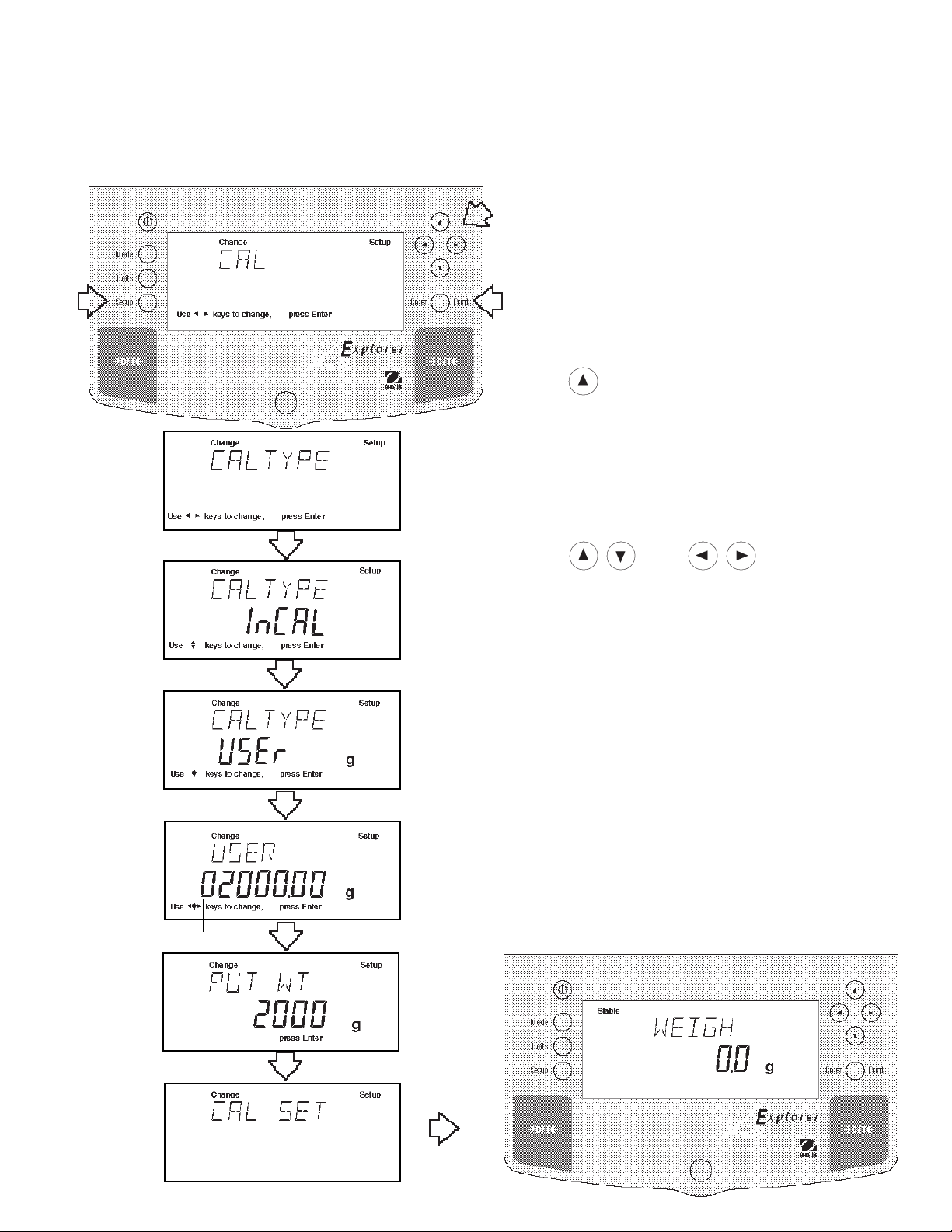
3.3.4 Span Calibration
Span calibration utilizes two calibration points, one at zero and the other at full span or incremental v alues starting at
25% of full capacity. As an example, an 8.1kg balance will accept either 2kg, 4kg, 6kg or 8kg for span calibration.
V alues which are belo w or in between will not be accepted and the balance will display its maximum capacity. When
LFT is set on, only full span calibration value can be used. Sample display illustrates an 8.1 kg balance
Procedure
• Press the Setup button, CAL is displayed.
• Press Enter button, CAL TYPE is displayed.
• Press Enter button, CAL TYPE InCAL is displayed.
• Press button to select SPAN calibration, CAL
TYPE SPAN is display ed.
• Press Enter button, W ORKING is displa y ed.
NOTE: If a weight is left on the pan, the balance will
display CLR PAN (remov e the w eight from the pan).
The balance automatically resumes calibration.
• Display changes to PUT WT 8000 g. The displayed
weight is the full capacity of the balance.
• Place specified calibration mass on pan.
NOTE: For an 8.1kg balance, either 2kg, 4kg, 6kg or
8kg can be used for span calibration. The PUT
WEIGHT message indicates the calibration mass that
is on the pan.
• Press Enter button, WORKING is displayed. After a
few seconds CAL SET is displayed, the display then
returns to WEIGH mode.
• Span calibration is completed.
• Remove calibration mass from the pan.
18
3.3.5 User Calibration
User calibration is used when it is desired to calibrate the balance using a mass of known value . When LFT is set on,
the balance will only accept full span calibration, 25%, 50% and 75% values are disabled. To use this calibration
feature, proceed as f ollows:
Procedure
• Press the Setup button, CAL is displayed.
• Press Enter button, CAL TYPE is displayed.
• Press Enter button, CAL TYPE InCAL is dis played.
• Press button twice to select USER calibration,
CAL TYPE USer is displa y ed.
• Press Enter button, the display indicates the last
calibration mass value which was entered with the
first digit flashing. (Sampleillustrates 2000g).
• Press and or and enter the
desired mass value. This number must be at least
25% of the full span value.
(FLASHING)
• Press Enter button, WORKING is displayed.
NOTE: If a weight is left on the pan, the balance will
display CLR PAN (remov e the w eight from the pan).
The balance automatically resumes calibration.
• Display changes to PUT WT 2000 g.
• Place specified calibration mass on pan.
• Press Enter button, WORKING is displayed. After a
few seconds CAL SET is displayed, the display then
returns to WEIGH mode.
• User calibration is completed.
• Remove calibration mass from the pan.
19

3.3.6 Linearity Calibration
Linearity calibration utilizes three calibration points, one at zero , center span and full span. This method minimizes
deviation between actual and displa yed weights within the balance's w eighing range . Three weight values are used;
zero, a weight v alue at midpoint of the balance's weighing range and a w eight v alue at or near the specified capacity.
Sample display illustrates an 8.1 kg balance.
Procedure
• Press the Setup button, CAL is displayed.
• Press Enter button, CAL TYPE is displayed.
• Press Enter button, CAL TYPE InCAL is displayed.
• Press button three times to select LIN calibration, CAL TYPE Lin is displa y ed.
• Press Enter button, WORKING is displayed.
NOTE: If a weight is left on the pan, the balance will
display CLR PAN (remo v e the weight from the pan).
The balance automatically resumes calibration.
• Display changes to PUT WT 4000 g. The displayed
weight is half the capacity of the balance.
• Place specified calibration mass on pan.
• Press Enter button, WORKING is displayed. After a
few seconds displa y changes to PUT WT 8000 g.
The display ed weight is the full capacity of the
balance.
• Place specified calibration mass on pan.
• Press Enter button, WORKING is displayed. After a
few seconds CAL SET is displayed, the display then
returns to WEIGH mode.
• Linearity calibration is completed.
• Remove calibration mass from the pan.
20

3.3.7 Calibration T est
Calibration test feature allows a check of a kno wn calibr ation mass against the last stored calibration information in
the balance. Sample displa y illustr ates an 8.1 kg balance.
Procedure
• Press the Setup button, CAL is displayed.
• Press Enter button, CAL TYPE is displayed.
• Press Enter button, CAL TYPE InCAL is displayed.
• Press button to select CALTEST calibration,
CALtESt is displayed.
• Press Enter button, W ORKING is displa y ed.
NOTE: If a weight is left on the pan, the balance will
display CLR PAN (remo v e the weight from the pan).
The balance automatically resumes calibration.
• Display changes to PUT WT 8000 g. The displayed
weight is the full capacity of the balance.
• Place specified calibration mass on pan.
• Press Enter button, WORKING is displayed. After a
few seconds, DIFF is displayed. The display nowindi
cates the actual difference in weight between what
value was just placed on the pan and the pre vious
weight value which was stored in the balance . After
approximately 8 seconds, the displa y returns to the
WEIGH mode.
• Remove calibration test mass from the pan.
21

3.3.8 Calibration GLP Printout
If any option in the GLP Set Menu is turned On, GLP automatically prints data after calibration is completed.
Span Calibration Printout
When performing Span calibration with all GLP options
turned on, a printout is automatically made after the
calibration is completed.
InCAL
When performing InCALTMcalibration with all GLP options
turned on, a printout is automatically made after the
calibration is completed.
TM
Calibration Printout
- - - - - SPAN CAL - - - - - -
12/01/97 1:00:00 PM
Bal Id 1234
Cal: 8000.00g
Old: 8000.00g
Dif: 0.00g
Wt. Ref ......................................
USER NO 2056853
PROJ NO 100012
Name........................................
- - - - - END - - - - -
- - - - - INCAL - - - - - 12/01/97 1:00:00 PM
Bal Id 1234
Cal: 8000.00g
Old: 8000.00g
Dif: 0.00g
Wt. Ref ......................................
USER NO 2056853
PROJ NO 100012
Name........................................
Linearity Calibration Printout
When performing a Linearity calibration with all GLP
options turned on, a printout is automatically made after
the calibration is completed.
Calibration T est Printout
When performing a Calibration Test with all GLP options
turned on, a printout is automatically made after the
calibration is completed.
- - - - - END - - - - -
- - - - - LIN CAL - - - - - 12/01/97 1:00:00 PM
Bal Id 1234
Cal: 8000.00g
Old: 7999.08g
Dif: 0.02g
Wt. Ref ......................................
USER NO 2056853
PROJ NO 100012
Name........................................
- - - - - END - - - - -
- - - - - CAL TEST - - - - - 12/01/97 1:00:00 PM
Bal Id 1234
Cal: 8000.00g
Act: 8000.02g
Dif: 0.02g
Wt. Ref ......................................
USER NO 2056853
PROJ NO 100012
Name........................................
22
- - - - - END - - - - -
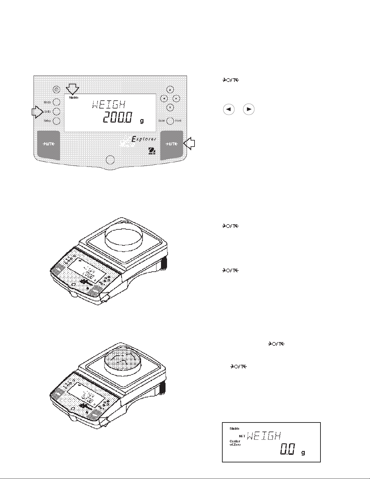
3.4 Weighing
NOTE: The Explorer balances are shipped with grams only enabled. When the balance is to be used with other
Type Approv ed/Legal for Trade units of measure, the desired unit must be enabled. Ref er to paragr aph 4.9 to
enable other measuring units.
Procedure
• Press to rezero the display.
• Press Units button to select measuring unit.
• Press or button for desired measuring unit.
•Press Enter button, balance is now ready for weigh
ing.
• Place the object(s) or material to be weighed on the
pan. Example illustrates a 200 gram weight.
• Wait for the stability indicator to appear bef ore reading the weight.
Zero/Tare
When weighing material or objects that must be held in a container, taring stores the container weight in the balance’s memory, separate from the weight of the material in the container .
Procedure
• Press with no load on the pan to set the
balance to zero.
(
Example
• Place an empty container on the pan. Its weight is
displayed.
• Press the display blanks until stab le w eight
readings are received, then indicates zero . The
container’s weight is stored in memory.
• Add material to the container. As material is added,
its net weight is displayed.
Container 200g)
• Removing the container and material from the plat-
form will cause the balance to display the container’s
weight as a negative number. The tared weight will
remain in memory until is pressed again or
the balance is turned off.
• Pressing resets the balance to zero .
NOTE: When Legal for Trade software option LFT NET
and LFT LOCK are both set ON, the balance indicates
NET WEIGH.
(
Example
Material 1620g)
23

3.5 Per cent Weighing
Percent W eighing is
permits you to place a reference load on the balance, then view other loads as a percentage of the reference. The
load you place on the pan as a reference ma y be displayed as any percentage you select from 5% to 100% (in 1%
increments). One hundred percent does not necessarily have to represent the reference load. Subsequent loads,
displayed as a percentage of the reference are limited only by the capacity of the balance. The default setting is
Reference 100%. Refer to paragraph 4.8 to enable percent w eighing.
enabled only
when Percent is turned ON in the Mode submenu under Setup . Percent weighing
Procedure
• Press the Mode button.
• Press or button until PERCENT is displayed.
• Press Enter button, PUT>PAN 100% is displa y ed. If
a container is used, the balance can be tared at this
point. The % display momentarily blanks while the
balance is taring out.
• Put the reference load on the pan.
• Press or button and select reference
weight percentage (P ercent Range 5 to 100). Hold
button down f or f ast change .
• Press Enter button to save setting, WORKING is
displayed ... calculating reference w eight.
Balance displays reference weight for five seconds in
selected measuring unit, then displays the percentage.
• Remove the reference weight from the pan and replace it with another load. The second load is displayed as a percentage of the ref erence .
NOTE: The PERCENT display (n umber of digits) is a
function of the accuracy of the balance and the size of
the reference weight. The displa y examples were with a
300g mass used with an 8.1 kilogram balance.
24

3.6 Parts Counting
Parts Counting is
Mode button. In the parts counting mode, the balance displa ys the quantity of parts you place on the pan. Since the
balance determines the quantity based on the average weight of a single part, all parts must be reasonably uniform in
weight.
enabled only
when Count is turned ON in the Mode submenu under Setup and selected with the
Procedure
• Press the Mode button.
• Press or button until COUNT is displayed.
• Press Enter button to sav e setting, PUT>PAN 10 PC
is displayed (def ault setting), balance will retain last
sample size sav ed.
• Press >O/T< if taring is required.
• Press or button and select sample size.
Sample size is 5 to 1000 pieces.
• Place sample size on the pan.
• Press Enter button to continue, display indicates
WORKING.
Balance displays the reference w eight of an individual
piece part for five seconds and then displays the total
number pieces on the pan.
• Remove the sample and place parts to be counted on
the pan. Balance displays number of pieces.
Update
Update is a function which permits placing additional
samples which are greater than the value of the original
sample but less than three times the value. This action
increases the accuracy of the measurement.
• Place sample on the pan which is at least one but not
more than three times the original sample size.
• Press Mode button, COUNT is displayed.
• Press Enter button, UPDATE is displayed.
• Press Enter button, WORKING is displa y ed then the
reference weight f ollow ed b y the new sample siz e .
25

3.7 Animal Weighing
Animal Weighing is
enabled only
when Animal is turned ON in the Mode submenu under Setup.
Procedure
• Press the Mode button.
• Press or button until ANIMAL is displayed.
• Press Enter button to continue, LEVEL is display ed.
• Press or button to change animal weighing
level, 0, 1, 2 or 3. 0 level represents an inactive
subject, 3 is used for a very active subject.
• Press Enter button to continue, AUTO is displa y ed.
• Press or button to select AUT O ON or OFF.
• Press Enter button to continue.
When the AUTO function is set ON, different subjects can
be weighed one after another without pressing any
buttons. When the balance displays READY, simply
place subject on pan.
Starting Animal Cycle
• Place animal container if used on pan.
• Press to tare the container.
• Place subject on pan.
• The animal cycle will automatically start if AUTO was
set to ON.
• Press Enter button to start animal cycle if AUTO was
set to OFF.
During Animal Cycle
• Display shows countdown to A W0.
Completed Animal Cycle
• Balance displays weight until subject is removed from
the pan.
26

3.8 Weigh Below
The Explorer balance is equipped with a weigh below
hook at the bottom of the balance. To use this feature,
remove power from the balance and remo ve the protective cover underneath the balance. See illustration for
location. The balance can be supported using lab jacks
or any other convienent method. Make sure the balance is level and secure . Apply power and operate the
balance. Attach items to be weighed to the hook
underneath the balance.
3.9 Printing Data
Printing data to an external computer or printer requires that the communications parameters in the Setup menu,
Print options and communication parameters be set first. Refer to page 25 Print menu settings and page 27 for
RS232 communication settings.
Procedure
• Press the Print button. Printing to an e xternal printer
or computer will occur each time the Print button is
pressed unless autoprint feature is turned on in which
case printing can occur in a continuous fashion, at
specified intervals or each time a stable reading is
achieved.
Sample printout is shown below with time turned on.
SAMPLE PRINTOUT
12/01/97 12:01:37 AM
429.5 g
For a review of of printing samples, refer to Section 4
Setting Up Your Balance . What is printed is controlled
by the GLP Set Menu and the selection of GLP Cont.
or GLP Tare in the Print Menu.
27

4. SETTING UP YOUR BALANCE
4.1 Setting Date and Time
Your Explorer balance provides date and time data which can be viewed on a computer or printed out on an external
printer. When y ou put y our ne w instrument into operation f or the first time , y ou should enter the current date and the
time. These settings are retained as long as the balance remains connected to a power source.
Date
Date is a feature which enables the balance to be set to a
U.S.A. date standard or European date standard. U.S.
standard has the month, date, followed b y the y ear, each
separated by (/) in the printout. The European date
standard has the day first, followed b y the month and
then the year; each separated by a period. The def ault
setting is U.S.A. Standard.
Procedure
• Press the Setup button, CAL is displayed.
• Press or button and select Date from the
menu.
• Press Enter button, TYPE is displa y ed.
• Press Enter button, SET M d y, d M y, y M d, M y d,
y d M, or d y M is displayed.
• Press or button and select type of date.
• Press Enter button, SAVED is displayed, then SET is
displayed.
• Press Enter button, first digit of date is flashing.
• Using arrow buttons, enter the correct date.
• When the correct date is entered, press Enter button,
SA VED displa ys momentarily and EXIT appears.
• Press Enter button, balance returns to a weighing
mode.
Time
Time is a feature which enables the balance to be set to
the current time in either U.S.A. standards (12 hour
periods) or European/Military standards (24 hour periods).
The default setting is U .S.A. Standard.
Procedure
• Press the Setup button, CAL is displayed.
• Press or button and select Time from the
menu.
• Press Enter button, TYPE is displa y ed.
• Press Enter button, TYPE 12 hr is displa y ed.
• Press or button and select 12 hr or 24 hr.
• Press Enter button, SA VED is displa y ed momentarily
then SET is displayed.
• Press Enter button,SET with time is flashing.
• Using arrow buttons, enter the correct time.
• When the correct time is entered, press Enter button,
SA VED displa ys momentarily and EXIT appears.
• Press Enter button, balance returns to a weighing
mode.
Adjustments up to +60 seconds a month can be made
to the balance internal clock. Repeat the first seven
steps, ADJUST is display ed. Using arrow buttons,
enter time correction and press Enter button.
28

4.2 Readout
The Readout menu is used to adapt the balance to environmental conditions. It contains four submenus: Stable,
Auto 0, Filter, Loc k and Exit. Lock enables you to program balance parameters and to loc k the settings .
Procedure
To select any of the items in the Readout menu, proceed
as follows:
• Press the Setup button, CAL is displayed.
• Press or button until READOUT is dis-
played.
• Press Enter button to sav e setting.
• Press or button until either STABLE, A U TO
0, FILTER, LOCK or EXIT is displayed.
• Press Enter button to save setting.
• Press or button and select the desired menu
setting.
• Press Enter button SA VED is displayed.
• Press or button to continue or EXIT.
• Press Enter button to sav e setting.
Stability
The stability range specifies the weighing results and must be within a preset tolerance limit for a certain time to turn
the stability indicator ON. When a displayed w eight changes be y ond the allowable range, the stability indicator turns
OFF, indicating an unstable condition. Factory default setting is sho wn in bold type .
.5 d Smallest range: stability indicator is ON only
when displayed weight is stable within .5 divisions.
1 d Reduced range .
2 d Normal range.
5 d Largest range, stability indicator is ON e v en though displa y ed w eight
changes slightly .
When the RS232 interface is configured to print stable data only, the stability range also gov erns data output. Displayed data will only be output if it is within the selected stability r ange .
Auto-Zer o
Auto-Zero minimizes the eff ects of temperature changes and shift on the z ero reading. The balance maintains the
zero display until the threshold is e xceeded. F actory default setting is sho wn in bold type.
OFFT urns Auto-Zero OFF.
.5 d Sets threshold to .5 divisions.
1 d Sets threshold to 1 division.
3 d Sets threshold to 3 divisions.
Filter
Filter compensates for vibration or excessiv e air currents. Def ault settings are shown bold.
-0- reduced stability, fastest stabilization time
-1- normal stability , normal stabilization time
-2- more stability, slow stabilization time.
Lock
Lock ON/OFF can only be changed when the hardware Lock Switch is set OFF/disabled. A menu is locked when the
menu lock is set ON and the Lock switch is ON. Loc k when selected and turned on, locks all of the entries made
under the Readout menu. In the locked condition, items may be look ed at b ut not changed in the menu. When set
off, entries may be changed. OFF is the default setting.
-3- maximum stability, slowest stabilization time.
29
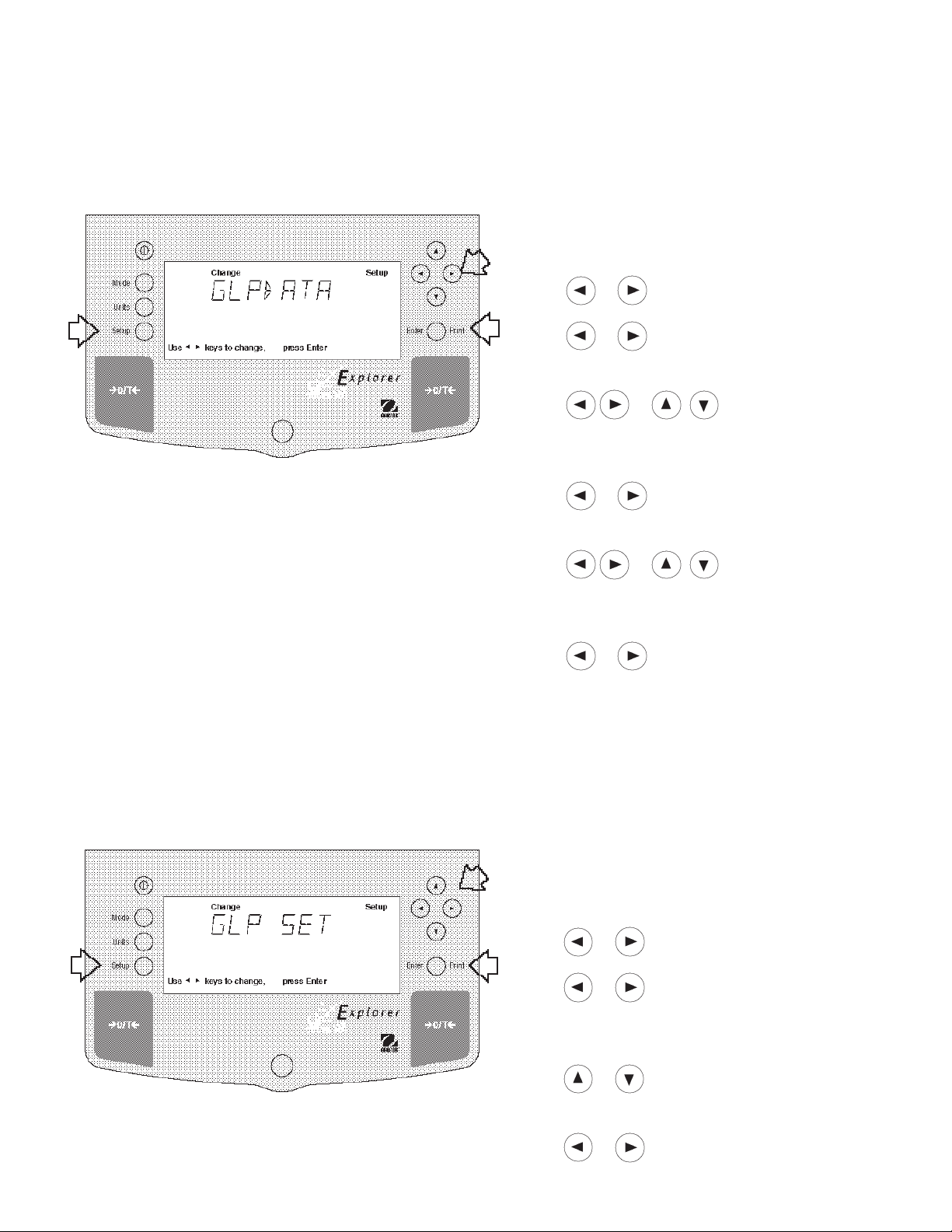
4.3 Good Laboratory Practices (GLP) Data
The GLP Data submenu enables the storage of a user identification number (7 digits) and/or a project number
(digits). When entered into the balance, the identification number and project number are a v ailab le when printing
providing they are turned on in the GLP Set submenu. A lock setting is also available which locks in the user identification and project number .
Procedure
To select any of the items in the GLP Data menu, proceed as follows:
• Press the Setup button, CAL is displayed.
• Press or button until GLP DAT A is displa yed.
• Press Enter button to continue.
• Press or button until either USER NO,
PROJ NO, LOCK or EXIT is displayed.
• Press Enter button to continue.
• Press or buttons as directed by
the display and enter a 7 digit number for the user ID
number.
• Press Enter button to sav e setting.
• Press or button until either USER NO,
PROJ NO, LOCK or EXIT is displayed.
• Press Enter button to continue.
• Press or buttons as directed by
the display and enter a 7 digit number for the project
number.
• Press Enter button to save setting.
• Press or button to select next item or EXIT.
• Press Enter button to continue.
4.4 Good Laboratory Practices (GLP) Set
Good Laboratory Practices (GLP) Set submenu allows the selection and will permit printing of Time, Balance Identification Number, User Identification Number, Project Number , Difference and Name data to be printed. When the
selected items are set to ON, these items are not displayed. The default setting is OFF. When an external printer is
used, and all items are set ON and the balance is calibrated, the printer will print out calibration data for audit trail
purposes and will indicate date, and time. (It should be noted that the User ID n umber and Project number must be
entered in the GLP Data submenu before printed data is availab le).
Procedure
To select any of the items in the GLP Set menu, proceed
as follows:
• Press the Setup button, CAL is displayed.
• Press or button until GLP SET is displayed.
• Press Enter button to sav e setting.
• Press or button until either TIME, BAL ID ,
USER NO, PROJ NO, DIFF, NAME, LOCK or EXIT is
displayed.
• Press Enter button to sav e setting.
• Press or button and select either ON or
OFF.
• Press Enter button to sav e setting.
• Press or button to continue or EXIT.
• Press Enter button to sav e setting.
30

4.5 Print
The Print menu provides a number of options which can be turned ON or OFF. It contains eight submenus: Auto
Print, feature which includes selection of Off, Continuous , Interval and on Stability, Inter , specifies time interval f or
automatic output of displayed data, Stable data-only feature, Numeric only or full display data f or output, GLPCont,
GLPT are, Reference which prints ref erence w eight v alue and Loc k which enab le y ou to prog ram balance param-
eters and to lock the settings.
Procedure
• Press the Setup button, CAL is displayed.
• Press or button until PRINT is displayed.
• Press Enter button to continue.
• Press or button until either AUTOPRT,
INTER, STABLE, NUMERIC , GLPCONT, GLPTARE,
REFEREN, LOCK or EXIT is displayed.
• Press Enter button to continue.
• Press or button and select either menu
setting or ON or OFF.
• Press Enter button to sav e setting.
• Press or button to select next item or EXIT.
• Press Enter button to continue.
Auto Print Feature
When enabled, the Auto Print feature causes the balance to automatically output display data in one of three ways:
continuously, at user specified time intervals, or upon stability. Default settings are shown bold.
OFF when set on turns off the auto print feature
Cont when set on, outputs printed data continuously
Inter provides a user specified printing interval
On Stb pro vides printed data only when a stab le reading is achie v ed
Interval
Can be set to provide a specified printing interval between 1 and 3600 seconds.
Print Stable Data Only
When set On , this feature permits only stable display data to be output. OFF is the default setting.
Print Numeric Data Only
When Numeric Data Only function is turned ON, this allows the balance to output numeric data only for RS232
output. OFF is the default setting.
31

4.5 Print (Cont.)
GLP Continuously
When the GLP Continuously function is set ON, allows the balance to output the GLP selections each time a weight
value is printed to the printer. OFF is the default setting. The following example is with GLP Cont On.
Sample Printout
GLP Set Menu
Options Turned On
12/01/97 12:01:37 AM
429.5 g
12/01/97 12:01:52 AM
Bal Id
429.8 g
12/01/97 12:02:17 AM
Bal Id
USER NO 1000001
429.8 g
12/01/97 12:02:43 AM
Bal Id
USER NO 1000001
PROJ NO 2000002
429.5 g
12/01/97 12:02:43 AM
Bal Id
USER NO 1000001
PROJ NO 2000002
Name . . . . . . . . .. . . . . .
429.5 g
Time = On
Time = On
Balance ID = On
Time = On
Bal ID = On
User No. = On
Time = On
Bal ID = On
User No = On
Proj No = On
Time = On
Bal ID = On
User No = On
Proj No =
Name = On
GLP Once After Tare
When the GLP Tare function is set ON, allows the balance to output the GLP selections once after tare when the
weight value is printed to the printer. OFF is the def ault setting. The following e xample is with GLP Once After Tare.
GLP Set Menu
Options Turned On
12/01/97 12:01:37 AM
429.5 g
429.6 g
429.7 g
429.7 g
429.7 g
Time = On
Reference
When the Reference function is set ON, prints the value of weight used as a ref erence in either Percent and Parts
Counting modes. OFF is the def ault setting.
Lock
Lock ON/OFF can only be changed when the hardware Lock Switch is set OFF/unlocked. A menu is locked when the
menu lock is set ON and the Lock Switch is ON. Lock when selected and turned on, locks all of the entries made
under the Print menu. In the locked condition, items may be look ed at but not changed in the menu. When set off,
entries may be changed. OFF is the default setting.
32
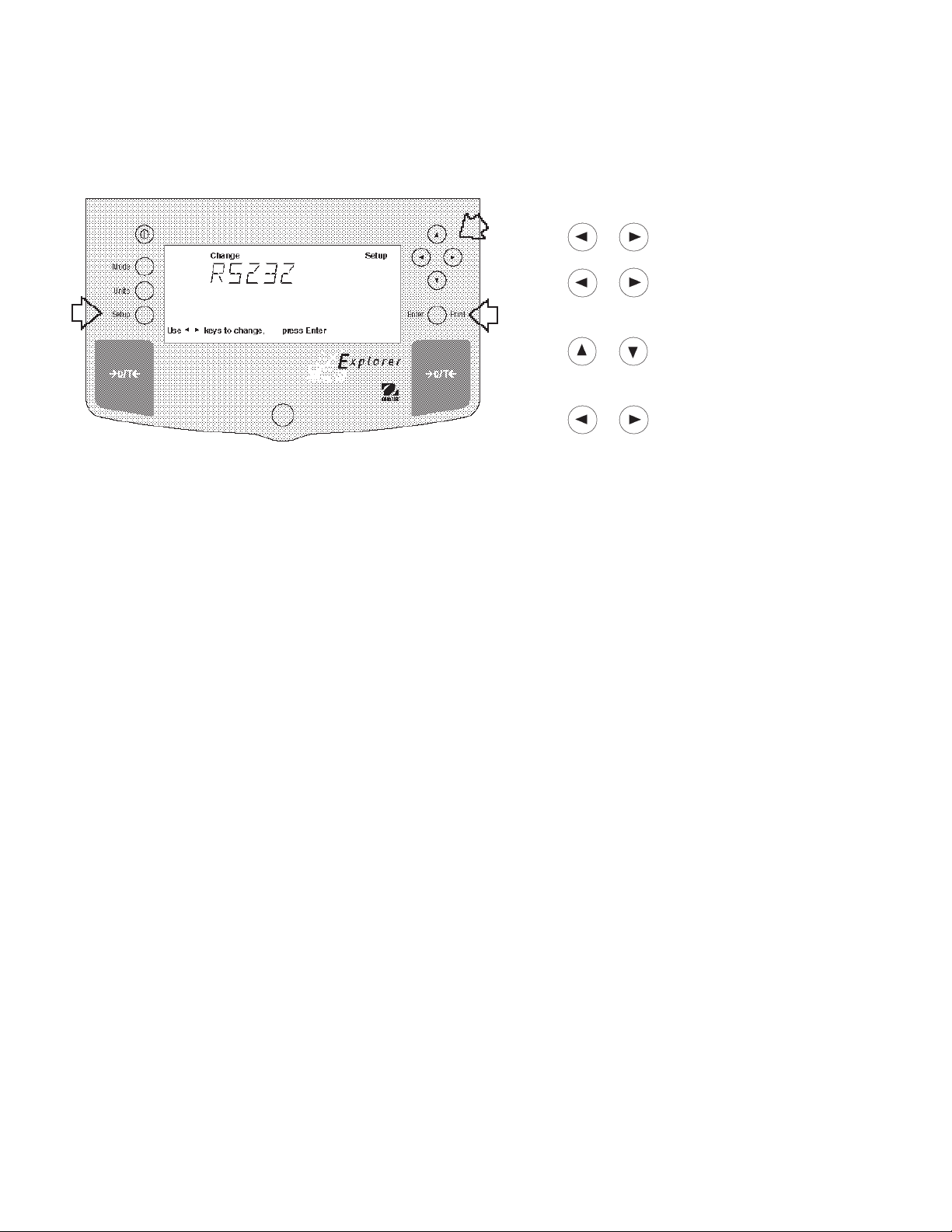
4.6 RS232
The RS232 menu provides communication parameters which can be set to accommodate e xternal printers or computers. It contains five submenus: Baud rate, Parity, Data, Stop bit and Lock ON or OFF which enable you to
program balance parameters and to lock the settings .
Procedure
• Press the Setup button, CAL is displayed.
• Press or button until RS232 is displayed.
• Press Enter button to sav e setting.
• Press or button until either BA UD, PARITY ,
DAT A, ST OP, LOCK or EXIT is display ed.
• Press Enter button to save setting.
• Press or button and select the desired
menu setting.
• Press Enter button to save setting.
• Press or button to continue or EXIT.
• Press Enter button to sav e setting.
Baud Rate
This submenu is used to select the desired baud rate. There are fiv e available baud rates to choose from: 300, 1200,
2400, 4800 and 9600. The default setting is 2400.
Parity
Parity can be set to Odd, Even or None . The default setting is None.
Data Bits
To set the number of data bits to 7 or 8. The default setting is 7.
Stop Bits
The number of stop bits can be set to 1 or 2. The default setting is 2.
Lock
Lock ON/OFF can only be changed when the hardware Lock Switch is set OFF/disabled. A menu is locked when the
menu lock is set ON and the Lock Switch is ON. Lock when selected and turned on, locks all of the entries made
under the RS232 menu. In the locked condition, items may be look ed at but not changed in the menu. When set off,
entries may be changed. OFF is the default setting.
33

4.7 Legal for Trade (LFT)
Legal for Trade (LFT) is a software controlled option which can be set to LFT LOCK. When LFT LOCK is set ON,
certain items in the Calibration, Readout, Print, Mode and Units menus are automatically preset and locked to permit
the balance to operate in a legal for trade application and works in conjunction with a Lock Switch. Default setting is
UNLOCKED . See default tab le.
Procedure
• Press the Setup button, CAL is displayed.
• Press button repeately until LFT is displayed.
• Press Enter button, LFT LOCK is displayed.
• Press Enter button, LFT LOCK OFF is displayed.
• Press or button and select either ON or OFF.
• Press Enter button, SA VED is momentarily display ed
followed by EXIT.
• Press Enter button, balance returns to weigh mode.
DEF AUL T T ABLE
LFT and Lock Switch Menu lock Default Value
Date Menu Unlocked
Time Menu Unlocked
NOTE: For legal for trade applications, the balance must
be physically sealed. Refer to section on LFT Sealing.
Calibration Menu
Span, Linearity, User Locked
CalTest Unlocked
Internal Calibration Unlocked
Cal Adj Locked
Cal Msg Locked ON
Readout Menu
Stability Unlocked .5d (limited to .5d and 1d)
Auto zero Unlocked .5d (limited to OFF and .5d)
Filter Level Unlocked -1GLP Data Menu Unlocked
GLP Selections Unlocked
Print Options Unlocked
RS232 Menu Unlocked
LFT Menu Lockswitch Locked
Function menu Locked Weigh
Units Menu Locked Grams*
Global Menu Locked
Custom Menu Unlocked
* Units oz and oz t cannot be simultaneously enabled.
If Print Numeric Data is turned ON, then Print Stable Data Only is
locked ON.
The display check countdown appears during the first
120 seconds after plugging in the balance and only when
the balance has been previously set with Type Approved/
Legal for Trade ON.
When the balance is first turned ON and LFT has been
previously set ON, the following display will appear if LFT
is set in the menu and the Lock Switch is set ON.
When the balance is first turned ON and LFT has been
previously set ON, the following display will appear if LFT
is set in the menu and Calibration menu is locked, and
the Lock Switch is set ON.
When LFT LOCK is turned ON, the weigh mode display
appears as shown below .
• • •
34

4.8 Mode
The Mode submenu permits the selection of five modes which can be turned ON or OFF. These modes are: Weigh,
Percent, Count, Animal and Lock. Weigh is turned ON and all others have a default setting of OFF. When any of
the modes are turned ON, they can be selected for operation from the Mode button.
Procedure
• Press the Setup button, CAL is displayed.
• Press or button until MODE is displayed.
• Press Enter button to sav e setting.
• Press or button until either WEIGH, PERCENT, COUNT, ANIMAL, LOCK or EXIT is displayed.
• Press Enter button to save setting.
• Press or button and select either ON or
OFF.
• Press Enter button to sav e setting.
• Press or button to continue or EXIT.
• Press Enter button to save setting.
Weigh
The Weigh submen u is always set to ON as a default.
Percent
Percent weighing permits you to place a reference load on the balance, then view other loads as a percentage of the
reference. Selection is made using the Mode button. The def ault setting is OFF.
Count
Counting is used when counting quanties of parts. Selection is made using the Mode button. The default setting is
OFF.
Animal
Animal weighing provides special settings to accommodate animal mov ements . Selection is made using the Mode
button. The def ault setting is OFF.
Lock
Lock ON/OFF can only be changed when the hardware Lock Switch is set OFF/disabled. A menu is locked when the
menu lock is set ON and the Lock Switch is ON. Lock when selected and turned on, locks all of the entries made
under the Mode menu. In the locked condition, items may be look ed at but not changed in the menu. When set off,
entries may be changed. OFF is the default setting.
35
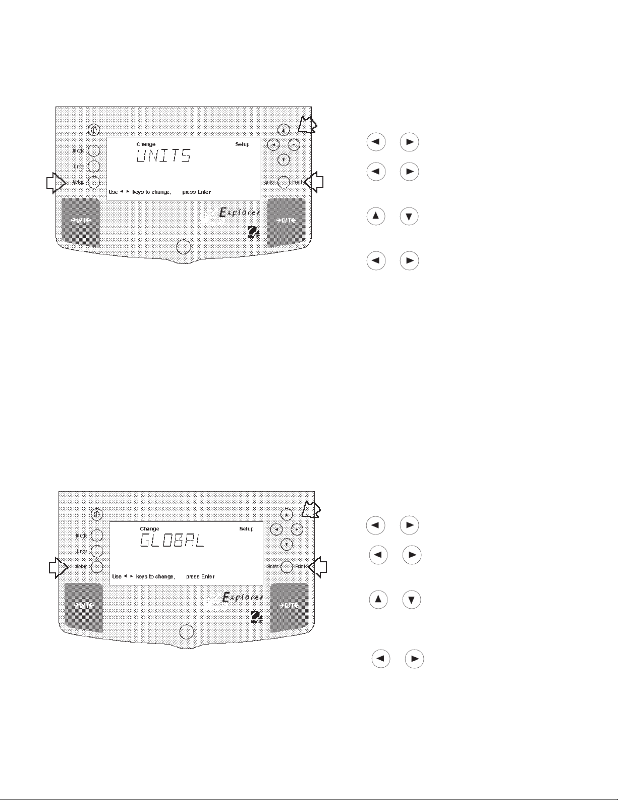
4.9 Units
The Units submenu permits the selection of the measuring units which can be turned ON or OFF and locked.
Procedure
• Press the Setup button, CAL is displayed.
• Press or button until UNITS is displayed.
• Press Enter button to continue.
• Press or button until desired measuring unit
is displayed.
• Press Enter button to continue.
• Press or button and select either ON or
OFF.
• Press Enter button to sav e setting.
• Press or button to select next item or EXIT.
• Press Enter button to continue.
Units
Measuring units settings are made using the Units button. This menu permits the measuring units to be turned ON or
OFF. The default setting is OFF.
Lock
Lock when selected and turned on, locks all of the entries made under the Units button. The default setting is OFF.
4.10 Global
This menu contains two functions which can be set to either a yes or no type of operation. These functions are: List,
and Reset. The default settings are NO. Global List is a con vienent method of examining which parameters are set
up in the balance. The parameters do not show up on the display b ut print out when selected. The Global menu
contains the List function. When Version is selected, the software re vision of the balance is displayed.
Procedure
• Press the Setup button.
• Press or button until GLOBAL is displayed.
• Press Enter button to continue.
• Press or button until either LIST, RESET,
VERSION, LOCK or EXIT is displayed.
• Press Enter button to continue.
• Press or button and select either YES or
NO for LIST and RESET. When either LOCK or EXIT
is selected, ON or OFF settings are availab le..
• Press Enter button to save setting.
• Press or button to select next item or EXIT.
• Press Enter button to save.
36

4.10 Global (Cont.)
List
This submenu can be used to output a listing of current menu settings via the RS232 interface. When YES is selected,
all menu settings will be output either to an external printer or computer. To use this feature, your balance must be
connected to a computer or printer. The default setting is OFF.
The partial sample shown, indicates the status in the
SAMPLE PRINTOUTS
menus.
EXPLORER xxxxxx-xxx
Sr #x.xx OS#x.xx G#x.xx
Time= 12hr 3:19:51 PM
Date= m/d/y 12/01/97
Function = Weigh
ReadOut Menu
Stb= 2 d
AZT= .5 d
Filter= 1
GLP Menu
Time/Date= On
Bal Id= On
User No.= On
Proj No.= On
DIFF= On
Name= On
Print Menu
Auto Print= Off
Interval= 7
Stable Print= On
NU= On
GLP Cont = Off
GLP on Tare = Off
Print Ref= On
RS232 = 2400: N: 7: 2
LFT is Off
Mode Menu
WEIGH= On
PERCENT= Off
COUNT= Off
ANIMAL= Off
Lock Switch is Off
Menu Locks
RS232= Off
READOUT= Off
GLPSET= Off
MODE= Off
UNITS= Off
PRINT= Off
GLP Data = Off
CAL= Off
GLOBAL= Off
CUSTOM= Off
Enabled Units:
g
custm
C. Units:
1.000000 E0 x 1
Reset
Reset when set to YES will reset the balance to factory default settings. The default setting is NO.
Version
Displays software re vision number for servicing purposes. This number is installed with the balance.
Lock
Lock when selected and set to ON, locks all of the entries made under the Global menu. The default setting is OFF.
37

4.11 Custom Unit
Custom Unit is enabled when Custom Unit Setup under Units Menu is turned ON. This feature can be used to create
your own custom weighing unit. It permits entering a conversion factor which the balance will use to conv ert grams to
the desired unit of measure.
Conversion W eight W eight
Factor x in = in
grams custom unit
Conversion f actors are e xpressed in scientific notation and entered
into the balance in three parts:
• a number between 0.1 and 1.999999 called the mantissa
• a power of 10 called the exponent
• a least significant digit (LSD)
SCIENTIFIC NOTATION
Number
Between
Con v . 0.1 and P o wer Man-
Factor 1.999999 of 10 tissa Exp.
123.4 = .1234 x 1000 = .1234 x 10
12.34 = .1234 x 100 = .1234 x 10
1.234 = .1234 x 10 = .1234 x 10
.1234 = .1234 x 1 = .1234 x 10
.01234 = .1234 x .1 = .1234 x 10
.001234 = .1234 x .01 = .1234 x 10
.000123 = .123 x .001 = .123 x 10
EXPONENTS
E-3 Moves decimal point 3
places to the left.
E-2 Moves decimal point 2
places to the left.
E-1 Moves decimal point 1
place to the left.
E0 Leaves decimal point
in normal position.
E1 Moves decimal point 1
place to the right.
E2 Moves decimal point 2
places to the right.
E3 Moves decimal point 3
places to the right.
3
2
1
0
-1
-2
-3
Procedure
• Press the Setup button.
• Press or button until CUSTOM is displayed.
• Press Enter button to sav e setting, FA CTOR is
displayed.
• Press Enter button, The mantissa of the current
conversion is displa yed. The mantissa of the current
conversion f actor is displayed. This is a number
between 0.1 and 1.999999 with the first digit flashing.
For conv ersion factors outside of this range, the
exponent will be used to mov e the decimal point.
• Press or buttons as directed by
the display and enter a 7 digit number for the conversion factor .
• Press Enter button, EXP (exponent) is displayed.
• Press Enter button, 0 (exponent) is display ed.
• Press or button and select exponent value
either -3, -2, -1, 0, 1, 2, or 3.
38
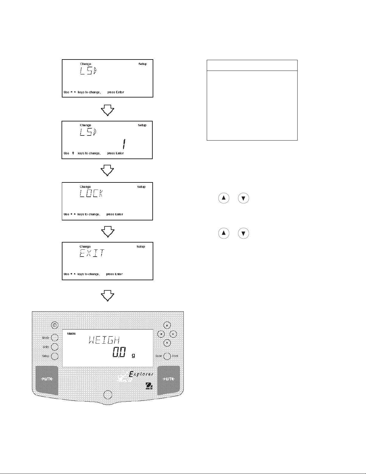
4.11 Custom Unit (Cont.)
LSD’s
LSD .5 Adds one decimal
place display counts by
5’s.
LSD 1 Display counts by 1’s.
LSD 2 Display counts by 2’s.
LSD 5 Display counts by 5’s.
LSD 10 Display counts by 10’s.
LSD 100 Display counts by
100’s.
Procedure (Cont.)
• Press Enter b utton to sa ve setting, LSD is displayed.
There are 6 LSD (least significant digit) settings you
can choose from (see table).
• Press Enter button, LSD 1 is displayed.
• Press or button and select LSD value either
1, 2, 5, 10 or 100.
•Press Enter button, SAVED is momementary displayed f ollow ed by LOCK.
•Press or button and select ON or OFF.
•Press Enter button, EXIT is displayed.
• Press Enter button to return to weighing mode.
39

4.12 Menu Lock-Out Protection
Access to the various menus can be disabled setting the Lock Switch located on the PC board inside the balance to
OFF position. The Lock Switch locks out all menus which have had LOCK turned ON. The default setting for the
Lock Switch is OFF.
Type Approved/Legal for Trade
Balance Sealing
All Explorer balances may be sealed for type appro v ed/
legal for trade applications. Type Approved balances
include a lead seal with wire and security screw as shown
in the figures.
For type approved balances consult local Weights and
Measures officials to determine sealing method requirements.
After the balance has been set up properly and the
menus are locked out, proceed to seal the balance.
Procedure
• Turn the display off and unplug the power cord.
• On balances with a draft shield, slide the door open
and remove the pan and cov er plate .
• On balances without a draft shield, remove the pan
and cover plate. Higher capacity balances with a 6"
or 8" pan do not have a co ver plate.
• Remove the protective s witch plate .
• The Lock Switch is located to the left of the pan
support hole.
• Select the desired position on the Lock Switch and
reassemble the balance.
Lead Seal
Example of Sealing Method
Lock Switch
shown in Locked
Position
Sealing Screw
Switch Plate
40

5 CARE AND MAINTENANCE
To keep the balance operating properly, the housing and platform should be kept clean and free from foreign material.
If necessary, a cloth dampened with a mild detergent may be used. Keep calibration masses in a safe dry place.
5.1 Troub leshooting
SYMPTOM
Unit will not turn on.
Incorrect weight reading.
Cannot display weight in desired
unit.
Unable to store menu settings/
changes.
RS232 interface not working.
PROBABLE CA USE(S)
Po wer cord not plugged in or
properly connected to balance.
Balance was not re-zeroed before
weighing.
Balance not properly calibrated.
Desired unit not enabled.
Enter was not selected.
Menu locked.
Print menu settings not properly
set up.
REMED Y
Check power cord connections.
Press with no weight on
the pan, then weigh item.
Recalibrate correctly .
Press Units button until desired
measuring unit is shown.
Enable units in Setup menu.
Press Enter when prompted.
Menu not locked properly.
V erify interface settings in RS232
menu correspond to those of
peripheral device.
Random segments displayed or
display locks up.
Unable to change
settings.
Unstable readings.
Error message display.
Cannot access weighing mode.
Cable connections.
Microprocessor locks up.
Menu locked
(Lock Switch set ON)
Excessive air currents.
Vibration on table surface.
Desired weighing mode is not
enabled.
Check cable connections.
Turn power off, then turn on again.
If condition persists, unit must be
serviced.
Set menu Lock OFF.
Set Lock Switch to OFF.
Check environmental conditions.
Place balance on a stable surface
or change averaging le v el.
See Error Codes list.
Press mode until desired weighing
mode is displayed.
Enable weighing mode.
41
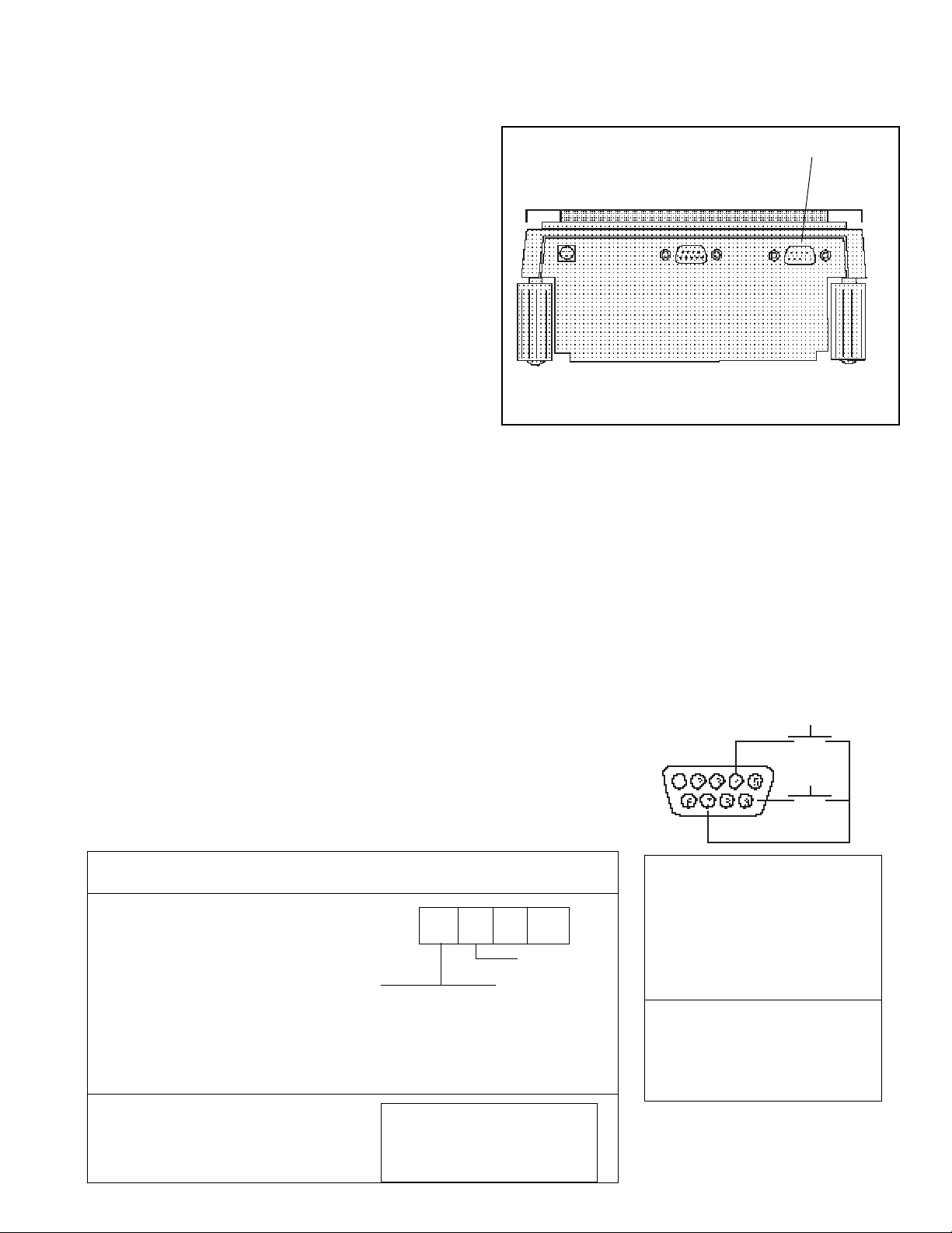
5.2 RS232 Interface
Explorer balances are equipped with a bi-directional
RS232 compatible interface f or communication with
printers and computers. When the balance is connected
directly to a printer, displa y ed data can be output at any
time by simply pressing PRINT, or b y using the Auto Print
feature.
Connecting the balance to a computer enables you to
operate the balance from the computer, as w ell as
receive data such as display ed w eight, weighing mode ,
stability status, etc.
The following sections describe the hardware and
software provided with the balance
Hardware
On the rear of the balance, the right-hand, 9-pin male
subminiature “D” connector is provided for interfacing to
other devices. The pinout and pin connections are sho wn
in the adjacent illustration.
The balance will not output any data unless pin 5 (CTS)
is held in an ON state (+3 to +15 V dc). Interfaces not
utilizing the CTS handshake may tie pin 5 to pin 6 to
defeat it.
Output Formats
Data output can be initiated in one of three ways: 1) By
pressing PRINT; 2) Using the Auto Print feature; 3)
Sending a print command (“P”) from a computer.
The output format is illustrated in the RS232 command
table which follows .
RS232 Connection
Rear of Balance
RS232 Commands
All communication is accomplished using standard ASCII
format. Characters sho wn in the following table are
acknowledged by the balance. Inv alid command response "ES" error indicates the balance has not recognized the command. Commands sent to the balance
must be terminated with a carriage return (CR) or
carriage return-line line feed (CRLF). F or example, a tare
command should appear as shown in the adjacent
diagram. Data output b y the balance is alw ays terminated
with a carriage return - line feed (CRLF).
TARE *
RS232 COMMAND TABLE
CommandCommand
Command
CommandCommand
CharacterCharacter
Character
CharacterCharacter
??
? Print current mode
??
nnnnAnnnnA
nnnnA Set Auto Print feature to “nnnn”
nnnnAnnnnA
DescriptionDescription
Description
DescriptionDescription
(see table).
Field: Mode Stab CR LF
Length: 5 1 1 1
blank if stable
“ ? ” if unstable
mg
GN
g
tael
kg
tael
dwt
tael
ct
momme
oz
lb
oz t
nnn = 0 Turns feature OFF
nnn = S Output on stability
nnn = C Output is continuous
nnnn = 1-3600 Sets Auto Print
N
tical
custm
Pcs
%
Interval
42
PRINT *
1 N/C
2 Data Out (TXD)
3 Data In (RXD)
4* Tare (External signal)
5 Clear To Send (CTS)
6 Data Terminal Ready (DTR)
7 Ground
8 Request To Send (RTS)
9* Print (External signal)
* External PRINT and/or TARE
switches may be installed
as shown in the diagram.
Momentary contact
switches must be used.

RS232 COMMAND TABLE (Cont.)
CommandCommand
Command
CommandCommand
CharacterCharacter
Character
CharacterCharacter
CC
C Begin span calibration
CC
xDxD
xD Set 1 second print delay (set x = 0 for OFF, or x = 1 for ON)
xDxD
FF
F Print current function.
FF
xx
II
x
I Set Averaging Filter Level to “x”,
xx
II
LL
L Begin linearity calibration
LL
xMxM
xM Places balance in mode “x”,
xMxM
DescriptionDescription
Description
DescriptionDescription
where x = 0 to 3 (see table).
If LFT, level 0 to 1.
where x = 1 to 17 (see table).
If unit or mode is not already
enabled, command will be ignored.
0 = minimum level
1=
2=
3 = maximum level
1 = milligrams
2 = grams
3 = kilo grams
4 = dwt
5 = Carats
6 = Ounces
7 = Ounces troy
8 = Grains
9 = Taels Hong Kong
10 = Taels Singapore
11 = Taels Taiwan
12 = Mommes
13 = Decimal Pounds
14 = (Not used)
15 = Newton's
16 = tical
17 = Custom Units
PP
P Print display data
PP
xSLxSL
xSL Set stable data only printing (set x = 0 to 3). If LFT 0 or 1.
xSLxSL
TT
T Same effect as pressing O/T button.
TT
VV
V Print EPROM version
VV
Esc VEsc V
Esc V Print balance ID (13 characters).
Esc VEsc V
xZxZ
xZ Set Auto Zero to “x”,where x = 0 to 3 ). 0=Off, 1=0.5d, 2=1d, 3=5d.If LFT,
xZxZ
x%x%
x% Set % reference function. Uses x (Real Number) as current Percent Reference.
x%x%
x#x#
x# Set PC reference function. Uses x (Real Number) as current Percent
x#x#
Field: Weight Mode Stab CR LF
Length: 9 1 5 1 1 1
When "numeric only"data is
selected for output in the
RS232 menu, the Mode field
is not output.
Displayed weight sent right justified
w/lead zero blanking.
Nine characters include:
decimal point (1)
weight (7 max)
polarity (1): blank if positive
"-" if negative
programs Auto zero level from 0 to 1.
Reference weigh must be entered in grams.
Reference. Reference weigh must be entered in grams.
Same as ?
command
43

RS232 COMMAND TABLE (Cont.)
CommandCommand
Command
CommandCommand
CharacterCharacter
Character
CharacterCharacter
Esc REsc R
Esc R Resets Setup and Print menus to factory defaults.
Esc REsc R
ONON
ON Turns balance on.
ONON
OFFOFF
OFF Turns balance off.
OFFOFF
##
# Print current Parts Count Reference Weigh.
##
% Print current Percent Reference Weigh.
xFxF
xF Set current function, set x for 0=None (normal weigh), 1=percent, 2=parts
xFxF
xAWxAW
xAW Set Animal Level from 0 to 3. 0= least amount of filtering.
xAWxAW
xExE
xE Set/Reset Auto Restart in Animal mode. Where x is 0=Off and 1=ON.
xExE
EE
E Start Animal cycle.
EE
xTxT
xT Download tare, tare weight must be entered in grams.
xTxT
IDID
ID Print Current User ID String.
IDID
xIDxID
xID Program User ID String, 1-8 characters.
xIDxID
DescriptionDescription
Description
DescriptionDescription
CAUTION: This will reset RS232 configuration.
Counting, 3=Animal Weighing. None
ACAC
AC Abort Calibration.
ACAC
xUCxUC
xUC User Weight Calibration.
xUCxUC
ICIC
IC Internal calibration (InCAL
ICIC
LELE
LE Show Last Error Code. Response: Err: Error Number.
LELE
SNSN
SN Show Serial Number.
SNSN
xSxS
xS Print Stable Only. Where x =0 Off and x=1 On.
xSxS
TIMETIME
TIME Print Current Time. Note, a ? mark will follow if date or time has not been set.
TIMETIME
mm/dd/yy SETDATEmm/dd/yy SETDATE
mm/dd/yy SETDATE Set Date Command and remove Invalid Indicator
mm/dd/yy SETDATEmm/dd/yy SETDATE
hh:mm:ss SETTIMEhh:mm:ss SETTIME
hh:mm:ss SETTIME Set Time Command and Remove Invalid Time Indicator
hh:mm:ss SETTIMEhh:mm:ss SETTIME
DATEDATE
DATE Prints Current Date. Note, a ? mark will follow the year if date or time has not
DATEDATE
W$TMW$TM
W$TM Write Clock Trim Value. The clock can be adjusted by + - 60 seconds a
W$TMW$TM
R$TMR$TM
R$TM Read Clock Trim value
R$TMR$TM
SETUPSETUP
SETUP Program Setup menu Options
SETUPSETUP
SWSW
SW Show Lockswitch status.
SWSW
been set.
month.
TM)
44

5.3 Error Codes List Error Codes List
The following list describes the various error codes and which can appear on the displa y and the suggested remedy.
Data Errors
1.0 Transient error (hardw are error, probably static discharge). If error persists, the balance must be
serviced.
1.1 Balance temperature transducer hardware error.
Tare Errors
2.0 Balance is unable to stabilize within time limit after taring. Environment is too hostile or balance needs
recalibration.
Calibration Errors
3.0 Incorrect or no calibration mass used for calibration. Recalibrate with correct masses.
RS232 Errors
4.4 RS232 buffer is full.
User Errors
7.0 User entry out of bounds.
7.2 Number outside of display capacity.
Over-Under Load Errors
8.0 Hardware error causing an internal weight signal which is too low. Check if pan is off. If not, the balance
must be serviced.
8.1 Hardware error caused by an internal weight signal which is too high. Chec k load on the pan which may
be excessive . If error persists, the balance must be serviced.
8.2 Power-on load out of specification (LFT only)
8.3 Rated capacity exceeded. Remove excessive weight from pan.
8.4 Underload condition on balance. Check that the proper pan is installed.
8.5 Internal calibration weight internal sensor indicated its weight on the pan.
CheckSum Errors
9.1 Bad factory checksum. If error persists, have the balance serviced.
9.2 Bad factory checksum. If error persists, have the balance serviced.
9.3 Bad factory checksum. If error persists, have the balance serviced.
9.4 Factory internal calibration data failed checksum. This failure will disable access to the InCAL
installed).
9.5 Factory calibration data failed checksum.
9.8 User calibration data failed checksum.
9.9 Factory temperature compensation data failed checksum.
5.4 Information Messages
CAL NOW If InCALTM (internal calibration) is installed. Message to recalibrate the balance. The
message will remain until calibrated.
WARM UP The user tried to perform an internal calibration and this message will be flashed in the 14
segment field. The balance requires a 7 minute warmup period. During warmup the user
can not select InCAL
SAVED This message is flashed when an item is changed in the menu and the new value is written
to the EEPROM.
LOCKED This message is flashed when an item can not be changed in the menu because the menu
is locked and the Lock Switch is set loc k ed.
LOW REF The message is flashed in parts counting or percent when the calculated reference weight
is very low .
UNSTBLE This message is flashed when the balance was unable to aquire stable data during internal
calibration.
TM
from the menu.
45
TM
feature (if

5.5 Service Information
If the Troubleshooting section does not resolve or describe your problem, you will need to contact an authorized
Ohaus Service Agent. For Service assistance in the United States, please call Aftermarket, Ohaus Corporation tollfree at (800) 526-0659. An Ohaus Product Service Specialist will be available to help you.
5.6 Replacement par ts
Description Ohaus Part No.
Po wer Pack, 100/120 V ac US Plug (Cord set part of power pack) 490202-01
Po wer P a ck, (Cord set required for UK, European and Australian) 490203-01
Cord Set, 230 V ac, UK Plug 76448-00
Cord Set, 230 V ac , European Plug 76212-00
Cord Set, 230 V ac, Australian plug 76199-01
5.7 Accessories
Description Ohaus Part No.
Calibration Masses - ASTM Class 1 T olerance:
20 g 49024-11
50 g 49054-11
100 g 49015-11
200 g 49025-11
500 g 49055-11
1 kg 49016-11
2 kg 49026-11
4 kg 49046-11
In-Use Display Cover Kit 470003-01
Security Device 470004-01
Draftshield Kit 470006-01
Density Determination Kit 470007-01
Modular Display Upgrade Kit 470008-01
Auxilliary Display Kit
(T ab le Mount) 470009-40
(Wall Mount) 470009-50
(Tower Mount) 470009-60
Remote Display Kit
(T ab le Mount) 470010-01
(Wall Mount) 470010-02
(Tower Mount) 470010-03
RS232 Interface Cable , Blunt end (user defined) AS017-01
RS232 Interface Cable, IBM
® -
PC 25 Pin AS017-02
RS232 Interface Cable , (connects impact printer) AS017-06
RS232 Interface Cable, IBM
RS232 Interface Cable, Apple
® -
PC 9 Pin AS017-09
®
llGS/Macintosh AS017-10
Printer AS142
46

5.8 Specifications Analyticals
Capacity (g) 62 110 162 210 100/210 *
Readability (mg) 0.1 0.1/1
Weighing modes g, mg, oz , oz t, ct, dwt, taels (3), mommes, gn, ti, N, custom unit
Functions Parts counting, animal weighing, percent
Options GLP, time, date, lockswitch, LFT (U.S.)/type approved
Repeatability (Std. dev.) (mg) 0.1 0.1/0.5
Linearity (mg) (+) 0.2 0.2/0.5
Tare range Full capacity by subtraction
Safe overload capacity 150% of capacity
Stabilization time <4 seconds
Sensitivity drift PPM/°C 3
(10°C - 30°C)
Operating temperature range:
w/internal calibration 10° to 40°C/ 50° to 104°F
w/o internal calibration 10° to 30°C/50° to 86°F
Calibration InCALTM calibration
Power requirements External Adapter, 100 -120 V ac, 220 - 240 V ac, 50/60 Hz
Draft shield (in/cm) 10.2/25.9
(free height above platform)
Display (in/cm) 0.6/1.5
Pan size (in/cm) 3.5/9. diameter
Plug configuration for US, Euro, UK, Japan & Australia
Dimensions 9 x 15.25 x14/22.8 x 38.7 x 35.5
(WxHxD) (in/cm)
Precision T op Loaders
Capacity (g) 210 410 100/410* 610 1550 2100 4100 1000/4100* 4100** 6100** 8100**
Readability (g) 0.001 0.001/0.01 0.01 0.01/0.1 0.1
Weighing modes g, mg, kg, lbs, oz , oz t, ct, dwt, taels (3), mommes, gn, ti, N, custom unit
Functions Parts counting, animal weighing, percent
Options GLP, time, date, lockswitch, LFT (U.S.)/type approved
Repeatability (Std. dev.) (g) 0.0005 0.0005/0.005 0.005 0.01/0.05 0.05
Linearity (g) (+) 0.002 0.002/0.005 0.02 0.02/0.05 0.1
Tare range Full capacity by subtraction
Stabilization time <3 seconds
Sensitivity drift PPM/°C 4 3 4 3 5 4 3 4 3
(10°C - 30°C)
Operating temperature range:
w/internal calibration 10° to 40°C/50° to 104°F
w/o internal calibration 10° to 30°C/50° to 86°F
Calibration InCALTM calibration
Power requirements External Adapter, 100 -120 V ac, 220 - 240 V ac, 50/60 Hz
Draft shield (in/cm) 10.2/25.9
(free height above platform)
Display (in/cm) 0.6/1.5
Pan size (in/cm) 4.7/12 Dia. 6.8 x 6.8/17.2 x 17.2 w/windshield 8 x 8/ 20.3 x 20.3 **
Dimensions 9 x 15.25 x14/22.8 x 38.7 x 35.5 8.25 x 4 x 14/20.9 x 10.1 x 35.5
(WxHxD) (in/cm)
* Moveable FineRange
** Balances with internal calibration are equipped with a 6" x 6" Pan and Windshield.
NOTE: Not all weighing modes apply depending upon capacity and resolution of the balance.
TM
Plug configuration for US, Euro, UK, Japan & Australia
47

LIMITED WARRANTY
Ohaus products are warranted against defects in materials and workmanship from the date of delivery through the duration of the warranty period. During the warr anty period Ohaus will repair, or , at its
option, replace any component(s) that proves to be defective at no charge, provided that the product
is returned, freight prepaid, to Ohaus.
This warranty does not apply if the product has been damaged by accident or misuse, exposed to
radioactive or corrosive materials, has foreign material penetrating to the inside of the product, or as
a result of service or modification by other than Ohaus. In lieu of a properly returned warranty
registration card, the warranty period shall begin on the date of shipment to the authorized dealer. No
other express or implied warranty is given by Ohaus Corporation. Ohaus Corporation shall not be
liable for any consequential damages.
As warranty legislation differs from state to state and country to country, please contact Ohaus or
your local Ohaus dealer for further details.
48

Ohaus Corporation
29 Hanover Road,
Florham Park, NJ 07932, USA
Tel: (973) 377-9000,
Fax: (973) 593-0359
With offices worldwide.
P/N 400040-014 © Ohaus Corporation 1999, all rights reserved.
49
 Loading...