

Page 1

MultiFrequency Phase Fluorometer
Installation and Operation Manual
Document Number MFPF-00000-000-02-1207
Offices: Ocean Optics, Inc. World Headquarters
830 Douglas Ave., Dunedin, FL, USA 34698
Phone 727.733.2447
Fax 727.733.3962
8 a.m.– 8 p.m. (Mon-Thu), 8 a.m.– 6 p.m. (Fri) EST
E-mail: Info@OceanOptics.com (General sales inquiries)
Orders@OceanOptics.com (Questions about orders)
TechSupport@OceanOptics.com (Technical support)
Page 2

Additional
Offices:
Ocean Optics Asia
137 Xianxia Road, Suite 1802, Changning District, Shanghai, PRC. 200051
Phone 86.21.5206.8686
Fax 86.21.5206.8686
E-Mail Sun.Ling@OceanOptics.com
Ocean Optics B.V. (Europe)
Geograaf 24, 6921 EW DUIVEN, The Netherlands
Phone 31-(0)26-3190500
Fax 31-(0)26-3190505
E -Mail Info@OceanOpticsBV.com
Copyright © 2001-2007 Ocean Optics, Inc.
All rights reserved. No part of this publication may be reproduced, stored in a retrieval system, or transmitted, by any means, electronic,
mechanical, photocopying, recording, or otherwise, without written permission from Ocean Optics, Inc.
This manual is sold as part of an order and subject to the condition that it shall not, by way of trade or otherwise, be lent, re-sold, hired out or
otherwise circulated without the prior consent of Ocean Optics, Inc. in any form of binding or cover other than that in which it is published.
Trademarks
All products and services herein are the trademarks, service marks, registered trademarks or registered service marks of their respective owners.
Limit of Liability
Ocean Optics has made every effort to make this manual as complete and as accurate as possible, but no warranty or fitness is implied. The
information provided is on an “as is” basis. Ocean Optics, Inc. shall have neither liability nor responsibility to any person or entity with respect to
any loss or damages arising from the information contained in this manual.
Page 3

Important Safety Notices
WARNINGS
1. Intense UV radiation is emitted from the MFPF LED. Do not look directly at the
LED output with the naked eye once the red cap is removed. To verify there is
power to the instrument, place a white piece of paper in front of LED 1.
2. Do not open the instrument case. High voltage is present. There are no
serviceable parts inside. Return the instrument to the factory for service.
MFPF-00000-000-02-1207 i
Page 4

Important Safety Notices
ii MFPF-00000-000-02-1207
Page 5

Table of Contents
About This Manual ..............................................................................v
Document Purpose and Intended Audience.................................................................... v
What’s New in This Document ........................................................................................ v
Document Summary........................................................................................................ v
Product-Related Documentation ..................................................................................... v
Chapter 1: Introduction.......................................................................1
MFPF System Overview.................................................................................................. 1
Applications ..................................................................................................................... 2
Models............................................................................................................................. 3
Shipment Components.................................................................................................... 3
Additional Recommended Equipment ............................................................................. 4
Chapter 2: Installation ........................................................................5
Overview ......................................................................................................................... 5
Software Installation ........................................................................................................ 5
Hardware Installation....................................................................................................... 10
Chapter 3: Configuration....................................................................13
Overview ......................................................................................................................... 13
Configuring Tau Theta Software ..................................................................................... 13
Configuring the COM Port ......................................................................................................... 13
Configuring MFPF Parameters.................................................................................................. 15
Configuring OOISensors Software for MFPF Unit........................................................... 17
Phase Fluorometer Tab for MFPF Systems in OOISensors ..................................................... 18
Appendix A: Specifications................................................................21
Index.....................................................................................................23
MFPF-00000-000-02-1207 iii
Page 6

Table of Contents
iv MFPF-00000-000-02-1207
Page 7

About This Manual
Document Purpose and Intended Audience
This document provides the users of the MultiFrequency Phase Fluorometer with instructions for setting
up, calibrating and performing experiments with their equipment.
What’s New in This Document
This version of the MultiFrequency Phase Fluorometer Installation and Operation Manual updates the
installation procedure.
Document Summary
Chapter Description
Chapter 1: Introduction Contains descriptive information about the MFPF unit. It also
provides a list of system requirements, interface options, and
shipment components.
Chapter 2: Installation Provides installation instructions.
Chapter 3: Configuration Contains steps to configure MFPF and OOISensors software
for use with the MFPF unit.
Product-Related Documentation
You can access documentation for Ocean Optics products by visiting our website at
http://www.oceanoptics.com. Select Technical → Operating Instructions, then choose the appropriate
document from the available drop-down lists. Or, use the Search by Model Number field at the bottom
of the web page.
• Detailed instructions for the OOISensors Software are located at:
http://www.oceanoptics.com/technical/NEW OOISensors FOXY Manual.pdf
Engineering-level documentation is located on our website at Technical → Engineering Docs.
You can also access operating instructions for Ocean Optics products from the Software and Technical
Resources CD that ships with the product.
MFPF-00000-000-02-1207 v
Page 8

About This Manual
vi MFPF-00000-000-02-1207
Page 9
Chapter 1
Introduction
MFPF System Overview
The MultiFrequency Phase Fluorometer (MFPF) is a flexible platform for measuring luminescence
lifetime, phase and intensity. The MFPF is a compact, self-contained, frequency-domain luminescence
monitor that uses LED excitation and photodiode detection with filter-based wavelength selection for
easy experimental set-up and control. Because the unit is self-contained, it is invariant to fiber bending
and stray light, and has a wide dynamic range of optical intensity as well as low optical and electronic
crosstalk, and low drift and phase noise. Therefore, the MFPF is especially useful for oxygen sensing
applications where sensitivity to drift is important and where sample set-ups must be left undisturbed for
long periods of time.
MFPF-00000-000-02-1207 1
Page 10

1: Introduction
The MFPF is used with Ocean Optics’ Fiber Optic Oxygen (FOXY) Sensors and custom probes. FOXY
Fiber Optic Oxygen Sensors are low-power, portable devices that offer high sensitivity, reversibility, and
stability. Their small size is useful for remote monitoring. What's more, the thin film used in the probe
tips consumes no oxygen, allowing for continuous contact with the sample. FOXY Sensors offer other
key advantages: they're ideal for viscous samples and are immune to interference caused by pH change or
from changes in ionic strength, salinity, and biofouling. The MFPF unit supports the following Ocean
Optics sensors (and their respective frequencies):
• FOXY (40 kHz) – Ocean Optics’ standard oxygen sensors designed for monitoring oxygen
partial pressure in gas and aqueous solutions. FOXY is a fiber optic fluorescence probe with
proprietary oxygen-sensing thin-film coating on the tip.
• HIOXY (40 kHz) – Designed for monitoring oxygen partial pressure in nonaqueous vapors
and solutions. The sensor coating chemistry is compatible with oils, alcohols, and
hydrocarbon-based vapors and liquids.
• FOSPOR (5 kHz) – A new generation of highly sensitive sensor coating for monitoring traces
of oxygen in gas and liquids.
See
http://www.oceanoptics.com/products/probes.asp for more information on probes
available from Ocean Optics.
The MFPF connects to a PC via USB connection and saves your data in an easy-to-use Microsoft Excel
format. The USB connection actually emulates the USB as a serial COM port. The MFPF can be
configured with two-channel LED excitation and detection, and modulation frequencies to 100 kHz. It
will give you lifetime measurements from 200 µsec down to 0.3 µsec. The on-board pressure transducer
measures atmospheric pressure or external pressure with a ¼-inch hose fitting.
The Tau Theta software manages the device and OOISensors software monitors its output via a DDE
software connection so that the Tau Theta software must be running in the background for the
OOISensors to work properly. Tau Theta software is Windows 2000/XP control software that measures
over a wide dynamic range of luminescence intensity, lifetime and phase, and allows you to select
channels, the LED frequency duty cycle and advanced instrument functions. OOISensors can support up
to four MFPF units; up to eight channels can be supported when OOISensors is used with MFPF100-2
(two-channel) units.
Applications
Typical applications include the following:
• Luminescent materials characterization
• Phase/lifetime-based sensor development
• Calibration of phase/lifetime-based sensors
• Stability and photodegradation studies
• Characterization of phase shift over frequency
2 MFPF-00000-000-02-1207
Page 11

2: Installation
• Oxygen consumption measurement on cell islet cultures
Models
Two models of the MFPF are available:
• MFPF100-1: Single-Channel MultiFrequency Phase Fluorometer. The single channel unit
comes complete with one thermistor.
• MFPF100-2: Two-Channel MultiFrequency Phase Fluorometer. The two-channel unit
includes two thermistors.
The thermistor option is used for temperature logging, calibration and temperature correction.
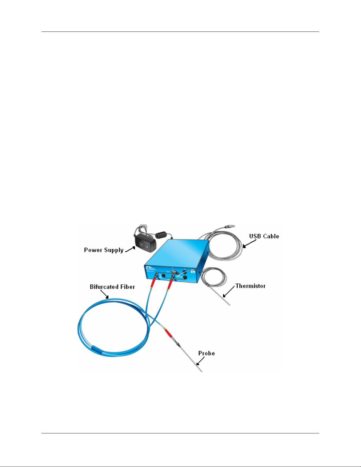
Shipment Components
The following equipment and information ships with the MFPF:
Single-Channel MFPF (MFPF100-1)
Includes one thermistor.
Or,
Two-Channel MFPF (MFPF100-2)
Includes two thermistors.
AC power supply
(Input AC100-240V, 50-60 HZ, 0.3A) (Output DC 6V 2A) (Model #EPAS-101W-06)
USB Cable
Software and Technical Resources CD
Each order ships with the Ocean Optics Software and Resources CD. This disc contains software,
operating instructions, and product information for all Ocean Optics software, spectrometers, and
MFPF spectroscopic accessories. You need Adobe Acrobat Reader version 6.0 or higher to view
these files. Ocean Optics includes the Adobe Acrobat Reader on the Software and Technical
Resources CD.
Ocean Optics software requires a password during the installation process. You can locate
passwords for the other software applications on the back of the Software and Technical
Resources CD package.
Packing List
The packing list is inside a plastic bag attached to the outside of the shipment box (the invoice
arrives separately). It lists all items in the order, the shipping and billing addresses, and any items
on back order.
MFPF-00000-000-02-1207 3
Page 12

1: Introduction
Additional Recommended Equipment
FOXY, HIOXY or FOSPOR Oxygen Sensor Probe
FOXY-CAL, HIOXY-CAL, FOSPOR-CAL
This is an optional factory calibration service for environments from 0 to 80ºC.
MFPF Software
The Tau Theta software runs in the background to gather data from the MFPF unit for the main
interface, OOISensors software.
OOISensor Software
OOISensors is an advanced data acquisition and display program that provides a real-time
interface to a variety of signal processing functions for users of Windows
95/98/ME/NT/2000/XP. OOISensors software supports USB2000 and USB4000 Spectrometers,
and the MFPF unit.
Bifurcated Fibers
4 MFPF-00000-000-02-1207
Page 13

Chapter 2
Installation
Overview
You must install the OOISensors software and the Tau Theta software applications prior to connecting the
MFPF to the computer to install the drivers required for the MFPF. If you do not install the software first,
the system will not properly recognize the MFPF.
CAUTION
Do not connect the MFPF unit included with the Fiber Optics Sensors System to the PC
prior to installing the OOISensors software.
Software Installation
Two types of software are used together to manage your MFPF instrument:
• OOISensors software – This is a 32-bit, advanced acquisition and display program that
provides a real-time interface to display and processing functions for use with Ocean Optics’
oxygen and pH sensors. OOISensors acquires data for use by the Tau Theta software to
convert data into concentration values, and save the data in spectral files and logs.
OOISensros can support up to four MFPF units.
Two additional software packages are also included as part of the OOISensors installer to set
up the USB port as a serial COM port and to communicate with the MFPF unit.
• Tau Theta software –This is the software application that controls and collects data from the
MFPF unit.
When working with MFPF units, this version of OOISensors relies on a basic version of the Tau Theta
software application that runs in the background and serves as the DDE host. It is the DDE host
application that actually controls the MFPF unit and reads the data. It then sends this information to the
OOISensors application using the DDE communications protocol.
The Tau Theta software is included as part of the OOISensors installation, so only one software
installation process is necessary.
MFPF-00000-000-02-1207 5
Page 14

2: Installation
► Procedure
To install OOISensors and Tau Theta software,
1. Close all other applications running on the PC.
2. Start the software installation process.
Installing from CD:
a. Insert the CD containing the OOISensors and Tau Theta software.
b. Select the drive on your computer with the software CD.
c. Double-click on the Setup.exe. The installation wizard appears.
Installing from the Web:
a. Go to
http://www.oceanoptics.com/technical/softwaredownloads.asp.
b. Right-click on OOISensors Oxygen Measurement Software and select Save Target As…
to download the executable to your machine.
c. Click Save. The installation begins.
d. Click Run. The Installation Wizard appears.
3. Click Next at the Welcome screen. The Choose Destination Location screen appears.
4. Accept the default or select another location for your software files. Click Next. The Backup
Replaced Files screen appears.
5. Select Yes or No, depending on whether you want to create backup replacement files. If you
select Yes, choose a location for these files. Then click Next. The Select Program Manager
Group screen appears.
6. Select the name of the Program Manager group to which you want to add the OOISensor icons.
Then click Next. The Start Installation dialog box appears.
7. Click Next. The Password dialog box appears. Type the password for your OOISensors software
and click OK. Passwords are located on the back of the software CD jacket. The software begins
installing.
The MFPF dialog box appears asking you if you have MFPF hardware.
6 MFPF-00000-000-02-1207
Page 15

2: Installation
8. Click Yes. A Tau Theta host application installer panel appears with its default destination path.
9. Keep the default values. Click Next.
10. A review of the MFPF installation appears in a window to show you if software needs to be
installed.
MFPF-00000-000-02-1207 7
Page 16

2: Installation
If the same or newer version of the Tau Theta software has already been installed, you can stop
the installation by clicking Cancel. Then click Yes to confirm the cancellation of the MFPF
installation.
If Tau Theta software must be installed, click Next. A set-up screen appears for OOISensors and
the LabVIEW runtime engine appears.
11. Keep the defaults. Click Next. A National Instruments License Agreement appears.
8 MFPF-00000-000-02-1207
Page 17

2: Installation
12. Click to accept the license agreement. Then click Next. An installation summary screen appears
for the OOISensors installation listing the components needed.
13. If the same or newer version of the OOISensors software has already been installed, you can stop
the installation by clicking Cancel. Then click Yes to confirm the cancellation of the OOISensors
installation.
If OOISensors software must be installed, click Next. The installation proceeds.
An Installation Complete screen appears, followed by a restart dialog box. Accept both to
launch the new software.
Access Tau Theta software with the
icon on your desktop. Access OOISensors software Start |
All Programs | Ocean Optics | OOISensors | OOISensors. If you attempt to start OOISensors software
without first starting the Tau Theta software, an error message appears.
MFPF-00000-000-02-1207 9
Page 18

2: Installation
Hardware Installation
WARNING
Ensure that the red plastic caps are covering the four SMA connectors on the front of the
MFPF unit. Intense UV radiation is emitted from the LEDS when the unit is powered-up.
Do NOT look directly at the LED output with the naked eye.
► Procedure
1. Unpack the equipment and verify that you have all the necessary components (see Shipment
Components
2. Connect thermistor(s) to T1 and T2 (for Model MFPF100-2) connectors on front of unit.
3. Locate the 21-02 SMA Splice Bushing that came with the probe. This item is a 0.75" screw with
two female ends. Screw one end of the splice bushing into the SMA 905 connector on the end of
the probe.
4. Locate the bifurcated fiber that came with the system. This optical fiber assembly has a “Y”
shaped design. Connect the common end of the bifurcated fiber to the splice bushing/probe.
and Additional Recommended Equipment).
5. Connect one arm (it doesn’t matter which one) of the bifurcated probe fiber to Ch1 LED and the
other arm to the Ch1 Detector on front of unit as shown below.
MFPF Unit Front Panel
6. Connect power cord from the power supply that came with your MFPF unit from back of unit to
an AC outlet. To check that the unit is receiving power, look for light glowing through the LED
#1 red cap, or place a piece of white paper in front of the LED if the red cap is not available. Do
NOT look directly at the light being emitted with the naked eye.
10 MFPF-00000-000-02-1207
Page 19

2: Installation
Caution
Use only the power supply that came with your MFPF unit. Using a different power supply
could damage your equipment.
7. Connect the MFPF unit to your computer using the USB cable.
Note
The current version of the MFPF uses a USB connection with an emulated RS232 port. Before
starting the Tau Theta software application, you must identify the COM port number of the
emulated RS232/USB port.
MFPF Unit Rear Panel
Once you have installed both the hardware and the software, you must configure your system (see
Chapter 3: Configuration
).
MFPF-00000-000-02-1207 11
Page 20

2: Installation
12 MFPF-00000-000-02-1207
Page 21

Chapter 3
Configuration
Overview
Once the software has been installed, the system has been rebooted, and the hardware has been connected
to the computer, you must configure the software.
Note
You must start the Tau Theta application software before starting OOISensors. If you attempt to
start OOISensors without the Tau Theta application running in the background, you’ll receive an
an error message stating that the DDE host could not be found. If multiple MFPF units are
connected to your computer on different USB ports, each unit requires its own copy of the Tau
Theta host program running in the background.
Configuring Tau Theta Software
You must identify the COM port given to the MFPF unit and set MFPF unit parameters using the Tau
Theta host program before using the MFPF unit(s) with OOISensors.
Configuring the COM Port
The MFPF unit uses a USB connection with an emulated RS232 port. When the MFPF is connected to the
computer, it is given a COM port number. Before you are permitted to start the software, you are asked to
identify the COM port number given to the emulated RS232/USB port.
► Procedure
To select the COM port for the emulated RS232/USB port,
1. Click the Windows Start icon.
2.
Select Control Panel | System to display the System Properties window.
MFPF-00000-000-02-1207 13
Page 22

3: Configuration
3.
Select the Hardware tab.
4.
Click Device Manager.
5. Scroll down and expand the Ports (COM & LPT) list item.
6. Note the port number assigned to the CP210x USB to UART device.
7. Ensure that this is the COM port selected on the Tau Theta software Set Up screen.
14 MFPF-00000-000-02-1207
Page 23

3: Configuration
8. Click Done.
Note
If you need to change the COM port number, double-click on the MFPF item in the Ports (COM
& LPT) list, select the Ports Settings tab, click the Advanced button, then assign a port number
between 1 and 8).
Configuring MFPF Parameters
You must set parameters for the MFPF unit using the Tau Theta host program. OOISensors cannot
control the MFPF unit. However, OOISensors does monitor for the number of active channel changes and
reconfigures the display accordingly
► Procedure
1. Double-click on the icon on the desktop. Note that you are asked for the MFPF unit’s the
COM port assignment. The main Tau Theta screen for the MFPF unit appears:
MFPF-00000-000-02-1207 15
Page 24

3: Configuration
2. Set the MFPF parameters (located in the Instrument Controls box on the lower left of the main
screen) according to the following recommendations:
Parameter Setting
Dual Channel Unchecked for set up, checked if 2 sensors are used
Sampling Period 2 seconds for set up
Frequency kHz 5 kHz – FOSPOR
40 kHz – FOXY and HIOXY
APD voltage 110 to 155 V photon-to-electron ratio
LED Channel Depends on your experiment
Detector Channel Depends on your experiment
3. Select Advanced | Show More Control Panel from the menu bar. The following dialog box
appears:
4. Set the parameters according to the following recommendations:
Parameter Setting
Analog AGC Checked
Digital AGC Checked
LED Mode Intermittent
LED Percentage 25 -- 100%
16 MFPF-00000-000-02-1207
Page 25

3: Configuration
Configuring OOISensors Software for MFPF Unit
The first time that you run OOISensors, you will be prompted to configure the software for use with your
hardware. Follow the steps below to configure OOISensors software.
► Procedure
1. Start the OOISensors software application. If this is the first time you have opened the software,
or if the software is not configured yet, the following screen appears:
2. Click MFPF.
Note
OOISensors is configured to work with the MFPF unit. However, you can change the
OOISensors configuration to work with spectrometers using the Configure | Software menu
item.
MFPF-00000-000-02-1207 17
Page 26

3: Configuration
Phase Fluorometer Tab for MFPF Systems in OOISensors
► Procedure
2. Click on the Phase Fluorometer tab in the Configure System screen to set the parameters for
systems using an MFPF unit. The MFPF configuration screen appears.
3. Select the first Device index (Device index 1).
4. Enter the known device serial number in the S/N box. You can find the serial number by selecting
Help | Support Info in the Tau Theta software.
5. Check the active checkbox. Depending on the MFPF’s configuration, Channel 1 and/or Channel 2
indicator LEDs will light the active channels detected. MFPF units come in single (MFPF100-1)
and dual-channel (MFPF100-2) versions. For dual-channel versions, the software can activate one
or both channels.
18 MFPF-00000-000-02-1207
Page 27

3: Configuration
6. Select the Color assigned to each channel.
7. Select one of the following for Calibration Order. This selection defines the required
calibration.
• Linear (Stern Volmer) – Requires a minimum of two oxygen standards for calibration.
• Second Order Polynomial – Requires a minimum of three oxygen standards for calibration.
8. Select the Oxygen Units.
9. If desired, check the Temperature checkbox. If you select this item, you need either a factory
multi-temperature calibration or you must perform one yourself. Once you have stored a multitemperature calibration in OOISensors, a single-temperature calibration will be required.
10. If desired, check the Pressure Compensation checkbox. If you select this item, you need to have
a pressure transducer that is supported by the hardware and software.
11. For Henry’s coefficients, select either User (user-specified), or the given Water values.
12. If there is more than one MFPF channel, fill in the same information for Channel 2.
13. Click OK to save your MFPF configuration.
MFPF-00000-000-02-1207 19
Page 28

3: Configuration
20 MFPF-00000-000-02-1207
Page 29

Appendix A
Specifications
Specification Value
LED Modulation Range 2 kHz to 100 kHz (200 µsec to 0.3 µsec)
Control Software Windows 2000/XP control software with data logging capability; controls
include: modulation frequency, data rate, LED duty cycle, signal averaging,
APD gain, analog gain, LED intensity
Measurement Modes Intermittent LED (to minimize photodegradation); Continuous LED (for rapid
measuring and accelerating photo-bleaching); Frequency sweep for
luminescence characterization
Thermistor Probes Closed-end stainless steel tube with thermistor sensor mounted in tip; liquid
immersible rugged design; 1/8” NPT fitting; temperature range 0 to 75 °C,
absolute maximum 100 °C+/- 0.2 °C; Interchangeable thermistors
Pressure Measurement On-board pressure transducer monitors atmospheric pressure, optional
configuration allows external connection for 0 to 15 psiA
Power, Input 6v - 12v, 1.5 Amps
Communications USB or RS-232
MFPF-00000-000-02-1207 21
Page 30

A: Specifications
22 MFPF-00000-000-02-1207
Page 31

Index
A
Adobe Acrobat Reader, 3
applications, 2
C
configuration, 18
configure
COM port, 13
OOISensors, 17
Tau Theta software, 13
D
document
audience, iii
purpose, iii
summary, iii
H
hardware, 10
I
Install
from CD, 6
from Web, 6
installation
hardware, 10
software, 5
O
OOISensors
configuring, 17
P
passwords, 3
Phase Fluorometer tab, 18
product-related documentation, iii
R
recommended equipment, 4
S
safety warnings, i
shipment components, 3
software, 5
OOISensors, 17
Tau Theta, 13
Software and Resources Library CD, 3
specifications, 21
T
Tau Theta software
configuring, 13
M
MFPF
front panel, 10
models, 3
overview, 1
rear panel, 11
MFPF-00000-000-02-1207 23
Page 32

Index
24 MFPF-00000-000-02-1207
 Loading...