

Page 1
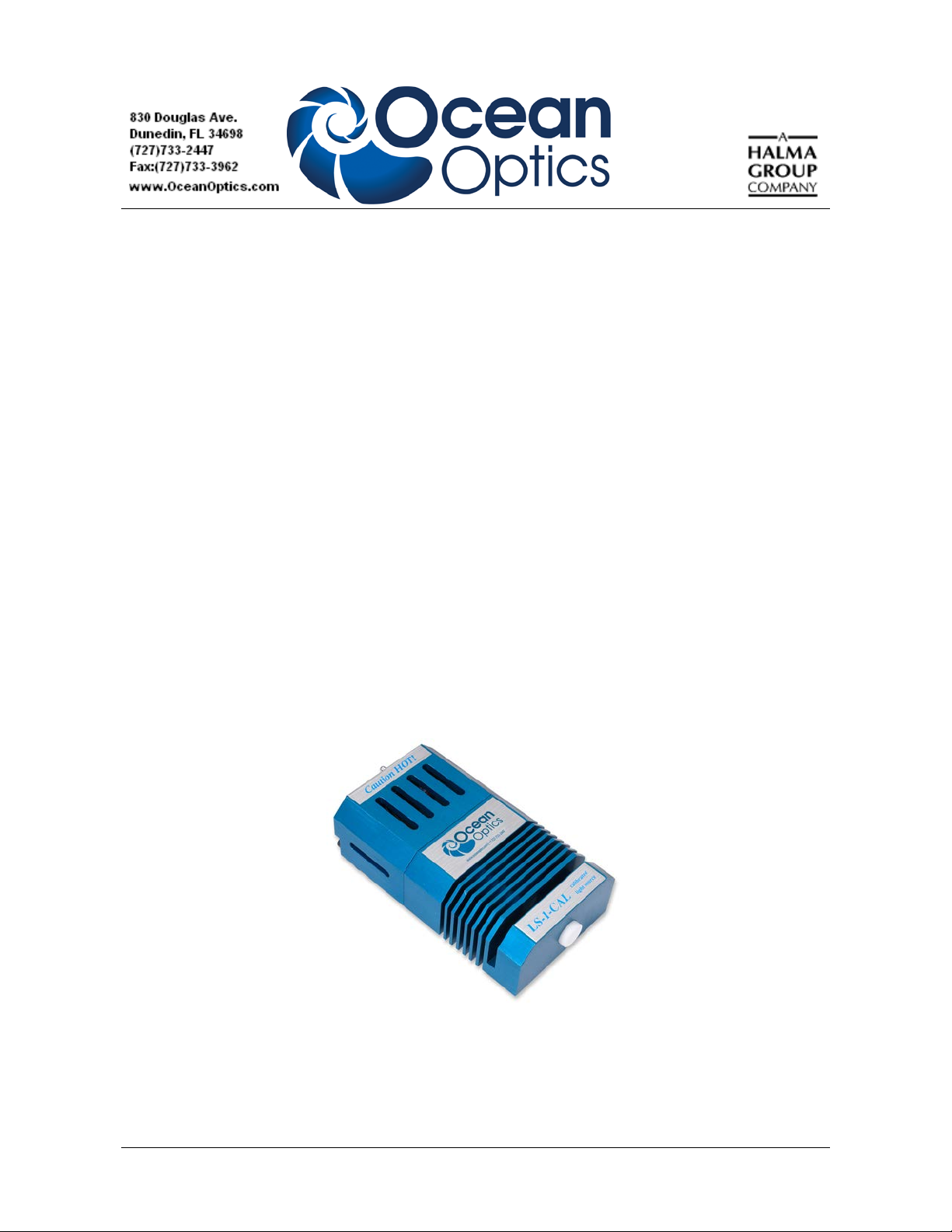
LS-1-CAL Seri es
Calibration Light Sources
Installation and Operation Instructions
Description
The LS-1-CAL and the LS-1-CAL-INT are tungsten halogen light sources that you can use to calibrate
the absolute spectral response of your system. Each light source emits a spectral intensity that is
calibrated by standards that provide traceability to the National Institute of Standards and Technology
(NIST).
The bulbs used in the LS-1-CAL and the LS-1-CAL-INT have a bulb life of 900 hours. Each lamp
also features a 12 VDC regulated power supply. The lamps are effective in calibrating the absolute
spectral response of a system from 350-1050 nm. When the lamps are combined with Ocean Optics
software, you can calculate the absolute spectral intensity of an emissive sample. Furthermore, each
light source can be used when calculating absolute irradiance or absolute irradiance and emissive color
(with Ocean Optics software).
009-00000-CAL-01- 201311 1
Page 2
LS-1-CAL Installation and Operation Instructions
The LS-1-CAL Series of calibrated light sources are designed for use in the VIS-Shortwave NIR
(350–1050 nm). It provides known absolute intensity values at several wavelengths, expressed in
µW/cm
2
/nm. Since the spectral intensity of the LS-1-CAL is traceable to the National Institute of
Standards and Technology (NIST), it is specifically designed for calibrating the absolute spectral
response of your system.
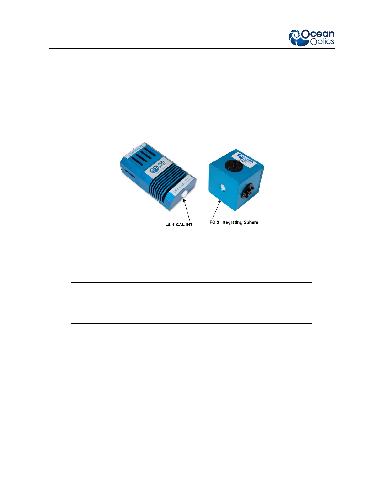
The primary difference between the LS-1-CAL and the LS-1-CAL-INT is the Teflon diffusion disc
that is installed in place of the SMA 905 Connector found on the LS-1-CAL. The LS-1-CAL-INT is
designed to work with the FOIS-1 Fiber Optic Integrating Sphere. The Teflon disc on the LS-1-CALINT fits snugly into the optical aperture on the FOIS-1, providing a uniform light source optimized for
the FOIS-1.
The LS-1-CAL-INT can be used with other integrating spheres. However, the optical aperture on the
integrating sphere must be large enough to accommodate the Teflon disc on the LS-1-CAL-INT, as the
Teflon disc must be fully inserted into the integrating sphere. The LS-1-CAL-INT is not effective
when the Teflon disc is placed up against an integrating sphere aperture that is too small to
accommodate the disc size.
Note
The LS-1-CAL is NOT designed to operate as an excitation source in your
experiments.
Parts Included
The LS-1-CAL Series light source ships with the following items:
LS-1-CAL or LS-1-CAL-INT Calibrated Light Source
Switching AC adapter (for power stabilization)
Power cord for the power supply
Floppy disk or CD containing calibration lamp report files (.lmp). The LS-1-CAL has two
lamp reports; one for using the LS-1-CAL with a bare fiber and one for using the LS-1-CAL
with a CC-3 cosine-corrected irradiance probe.
2 009-00000-CAL-01- 201311
Page 3
LS-1-CAL Installation and Operation Instructions
Additional Accessories
The following are additional accessories available from Ocean Optics that you may need, depending
on your system set-up:
• Spectrometer
• SMA-terminated optical fiber or CC-3 cosine-corrected irradiance probe
• Ocean Optics software
WARNING
The light source becomes extremely hot during operation and does not contain a
cooling fan. Handle with extreme care during operation.
Connecting the Light Source
The set-up procedure differs slightly, depending on whether you are connecting the LS-1-CAL to a
bare fiber or a cosine corrector. The LS-1-CAL-INT connects to an integrating sphere such as the
Ocean Optics FOIS-1 Fiber Optics Integrating Sphere.
Connecting the LS-1-CAL
► Procedure
1. Use a 0.050 Allen wrench to loosen the setscrew on the SMA connector of the LS-1-CAL.
2. If using a bare fiber with the LS-1-CAL:
a. Remove the inner barrel from the SMA connector.
b. Screw this connector barrel onto the end of the fiber until the connection is tight.
c. Insert the barrel and fiber completely into the SMA connector of the LS-1-CAL.
If using a CC-3 cosine corrector with the LS-1-CAL:
a. Remove the inner barrel from the SMA connector.
b. Screw the CC-3 cosine corrector onto the end of the fiber until the connection is tight.
c. Insert the CC-3 and fiber completely into the SMA connector of the LS-1-CAL.
3. Use the Allen wrench to tighten the setscrew on the SMA connector or CC-3 of the LS-1-
CAL.
4. Screw the other end of the fiber into the SMA connector of the spectrometer.
5. Plug the switching AC adapter (black rectangular box) into the back of the LS-1-CAL. This
adapter stabilizes the power coming into the lamp to insure constant spectral intensity
6. Plug the power cord into the back of the switching AC adapter, then plug the other end of the
power cord into a standard outlet.
7. Switch the lamp on using the on/off switch on the back of the LS-1-CAL.
009-00000-CAL-01- 201311 3
Page 4

LS-1-CAL Installation and Operation Instructions
8. Allow the lamp to warm up for at least 30 minutes before proceeding.
You have now connected the LS-1-CAL for operation.
Connecting the LS-1-CAL-INT
► Procedure
1. Connect the Teflon disc on the LS-1-CAL-INT into the optical aperture on the FOIS-1.
2. Plug the switching AC adapter (black rectangular box) into the back of the LS-1-CAL-INT.
This adapter stabilizes the power com ing into the lamp to insure con stant spe ct ral in tensi ty
3. Plug the power cord into the back of the switching AC adapter, then plug the other end of the
power cord into a standard outlet.
4. Switch the lamp on using the on/off switch on the back of the LS-1-CAL-INT.
5. Allow the lamp to warm up for at least 30 minutes before proceeding.
You have now connected the LS-1-CAL-INT for operation.
Calibrating With the Light Source
► Procedure
Follow the steps below to calibrate the spectral response of your system using the LS-1-CAL or
LS-1-CAL-INT:
1. Insert the CD that came with the light source that contains the ASCII file (.lmp) of the Lamp
Calibration Report.
The LS-1-CAL has two lamp files. One file has the calibration numbers for cal ib rating the
spectral response of your system with the lamp and a bare fiber; the name of this file contains
the lamp’s serial number followed by FIB.LMP. The other file has the calibration numbers for
calibrating the spectral response of your system with the lamp and a CC-3 cosine corrector;
the name of this file contains the lamp’s serial number followed by CC.LMP (for example,
123_FIB.LMP or 123_CC.LMP).
2. Copy the lamp file(s) to your computer.
3. Start your software and foll ow the instructions for calibrating your spectrometer for absolute
irradiance measurements. Be sure to do the following:
• Select the proper lamp file that matches your configuration.
• If using a bare fiber, enter the fiber diameter.
• If using a fiber with a CC-3 cosine corrector, enter 3,900.
• If using a LS-1-CAL-INT, select Integrating Sphere.
4 009-00000-CAL-01- 201311
Page 5

LS-1-CAL Installation and Operation Instructions
Note
You must use whatever optical setup you choose for your application when calibrating
the spectral response of your system. For example, if you are going to use a 200-µm
fiber and a CC-3 for your application, you must use the same components when
calibrating the spectral response of your system.
4. Verify that the lamp was ON for approximately 30 minutes prior to calibrating your
spectrometer.
5. Ensure that nothing is blocking the light path to the spectrometer and that the conditions for
the reference scan are identical to those you will use for your sample.
Note
You must always take a dark measurement before taking an absolute irradiance
measurement.
You have now calibrated the spectral response of your system.
Maintenance
LS-1-CAL and LS-1-CAL-INT maintenance must be done at the Ocean Optics factory:
• Recalibration: You should have the LS-1-CAL and LS-1-CAL-INT recalibrated after every 50
hours of use. Contact an Ocean Optics Application Sales Engineer for information on lamp
recalibration.
• Bulb replacement: You cannot change the bulb in the LS-1-CAL and LS-1-CAL-INT, as a
recalibration is required when the bulb is replaced. Contact an Ocean Optics Application Sales
Engineer for information on bulb replacement.
009-00000-CAL-01- 201311 5
Page 6

LS-1-CAL Installation and Operation Instructions
Specifications
Lamp Specifications
Specification Value
Dimensions (mm) LxWxH 90 x 50 x 32 mm
Weight 370 g
Power consumption 12 VDC/800 mA (regulated)
Power output 6.5 watts
Spectral range 350–1050 nm (calibrated)
Connector
LS-1-CAL
LS-1-CAL-INT
Output to bulb 5 volts/1.3 amps
Time to stabilized output ~30 minutes
Output regulation 0.2% voltage
SMA 905 for fiber; 6.35 mm barrel for cosine corrector
PTFE for integrating sphere
Spectral Output
Spectral Output of the LS-1-CAL Using a Bare SMA-terminated Fiber
6 009-00000-CAL-01- 201311
Page 7

LS-1-CAL Installation and Operation Instructions
Spectral Output of the LS-1-CAL Using the CC3 Cosine Corrector
Spectral Output of the LS-1-CAL-INT When Connected to a FOIS-1 Integrating Sphere
009-00000-CAL-01- 201311 7
Page 8

LS-1-CAL Installation and Operation Instructions
8 009-00000-CAL-01- 201311
 Loading...