

Page 1
LLS Series LED Light Sources
Installation and Operation Instructions
Description
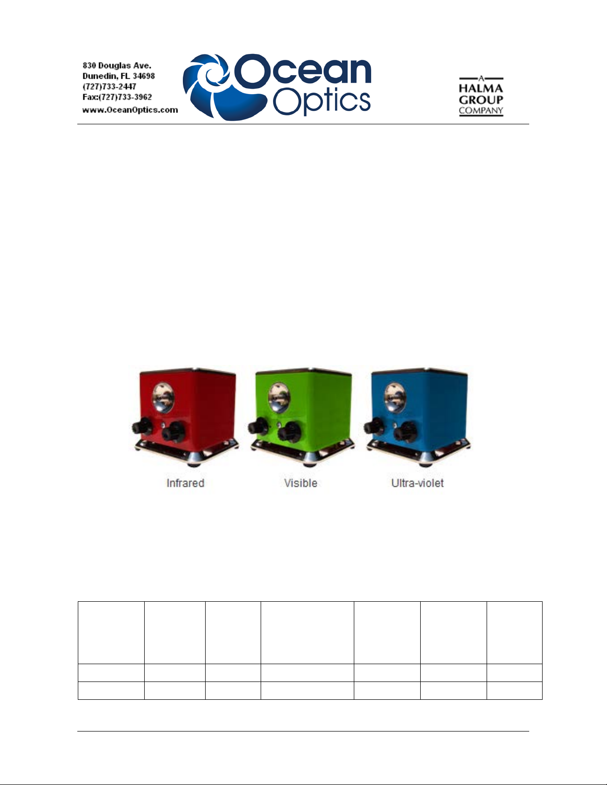
Ocean Optics’ LED Series light sources (LLS) are engineered to be a versatile tool for scientific and
general lighting applications. Light is coupled directly into a fiber with the highest efficiency possible
via the SMA 905 connection. You can adjust the optical intensity in continuous (CW) and pulse
modes. The LLS Series support a ‘pulse mode’ to allow higher current and thus higher optical power
when in pulsed mode. The LLS module is designed to accommodate external control of intensity,
pulse and lamp on/off. This system also has the ability to have interchangeable light modules.
LLS Series Light Sources
LLS Models
LLS LED light sources are available in nearly 50 different wavelength options. See the table below for
a list of models.
Max. Duty
Min. Power
Coupled into a 600
Part Number Wavelength FWHM
LLS-240 240 10 nm 2μW 20mA 200mA 1%
LLS-245 245 10 nm 2μW 20mA 200mA 1%
300-00000-011-01-201301 1
µm .22NA Fiber
Max. Drive
Current CW
Max. Drive
Current
Pulsed
Cycle in
Pulsed
Mode
Page 2
LLS Series Installation and Operation Instructions
Max. Duty
Min. Power
Coupled into a 600
Part Number Wavelength FWHM
LLS-250 250 12 nm 5μW 20mA 200mA 1%
LLS-255 255 12 nm 5μW 20mA 200mA 1%
LLS-260 260 12 nm 15μW 20mA 200mA 1%
LLS-265 265 12 nm 15μW 20mA 200mA 1%
LLS-270 270 12 nm 15μW 20mA 200mA 1%
LLS-275 275 12 nm 15μW 20mA 200mA 1%
LLS-280 280 12 nm 15μW 20mA 200mA 1%
LLS-285 285 12 nm 15μW 20mA 200mA 1%
LLS-290 290 12 nm 15μW 20mA 200mA 1%
LLS-295 295 12 nm 15μW 20mA 200mA 1%
LLS-300 300 12 nm 15μW 20mA 200mA 1%
LLS-305 305 12 nm 15μW 20mA 200mA 1%
µm .22NA Fiber
Max. Drive
Current CW
Max. Drive
Current
Pulsed
Cycle in
Pulsed
Mode
LLS-310 310 10 nm 15μW 20mA 200mA 1%
LLS-315 315 10 nm 15μW 20mA 200mA 1%
LLS-325 325 12 nm 15μW 20mA 200mA 1%
LLS-335 335 15 nm 20μW 20mA 200mA 1%
LLS-345 345 15 nm 20μW 20mA 200mA 1%
LLS-355 355 15 nm 20μW 20mA 200mA 1%
LLS-365 365 10nm 1mW 500mA 1000mA 50%
LLS-385 385 10nm 1mW 500mA 1000mA 50%
LLS-405 405 15nm 750μW 500mA 1000mA 50%
LLS-455 455 18nm 1mw 1000mA 2000mA 50%
LLS-470 470 18nm 1mw 1000mA 2000mA 50%
LLS-490 490 20nm 1mw 1000mA 2000mA 50%
LLS-505 505 20nm 1mw 1000mA 2000mA 50%
LLS-530 530 30nm 750μW 1000mA 2000mA 50%
LLS-590 590 20nm 750μW 700mA 1500mA 50%
LLS-617 617 20nm 750μW 700mA 1500mA 50%
LLS-627 627 20nm 750μW 700mA 1500mA 50%
LLS-Cool
White
2 300-00000-011-01-201301
6500K
CCT N/A
1mw (measured at
550nm) 1000mA 2000mA 50%
Page 3
LLS Series Installation and Operation Instructions
Part Number Wavelength FWHM
Min. Power
Coupled into a 600
µm .22NA Fiber
Max. Drive
Current CW
Max. Drive
Current
Pulsed
Max. Duty
Cycle in
Pulsed
Mode
LLS-Neutral
White
LLS-Warm
White
4100K
CCT N/A
3000K
CCT N/A
1mw (measured at
550nm) 1000mA 2000mA 50%
1mw (measured at
550nm) 1000mA 2000mA 50%
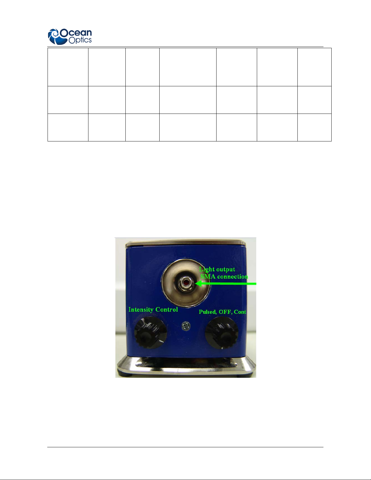
Controls
The LLS Light source features two control knobs on the front. The knob on the right controls the input
mode. The switch turned fully clockwise is the continuous mode, “off” is the middle po sition and fully
counter-clockwise is pulse mode. Remember that an external trigger is required for pulsing. This can
be accomplished via a cable connected to your electronics, or through an optional USB controller.
The left knob controls intensity. Turn clockwise for maximum intensity. The intensity control will
work in both pulse and continuous modes.
Front View of LLS Light Source
300-00000-011-01-201301 3
Page 4

LLS Series Installation and Operation Instructions
Light Source Connection and Operation
External interface is accomplished through a female high density DB15 connector. All external signals
are TTL compatible and will work with 3.3V or 5V logic. Please see DB15 Connector for a complete
list of pins.
The lamp can be externally turned off when in continuous mode by controlling pin 3. The signal is
internally pulled high and will return to ON when no low level signal is present.
Rear View of Cool Red Light Source
Pin 1 is the external trigger for pulse mode. See External Triggering and Control for more detailed
information. Never modulate this pin with a greater duty cycle and current than recommended by
the LED manufacturer as damage to the LED can result.
DB15 Connector
Pin # Description
1 Pulsed input (rising edge). Use for pulsed mode
2 Pulse end output. This pin goes high at the end of the internal fixed length pulse.
3 Lamp enable (used in CW only)
4 5 volt output. Can be used to power external controller.
5 Address line A1 (for onboard EEPROM) 24LC64
6 Address line A2 (for onboard EEPROM) 24LC64
7 SCL for I2C EEPROM
8 SDA for I2C EEPROM
9 Ground
10 Ground
11 3.3V input for I2C EEPROM (required for accessing memory)
4 300-00000-011-01-201301
Page 5

LLS Series Installation and Operation Instructions
Pin # Description
12 N/A
13 N/A
14 N/A
15 Analog Control Input (requires a jumper change to use.) Never exceed 2.5Volts into
this pin.
External Triggering and Control
There are two sets of internal jumpers located on the main PCB board. These are accessible by
removing the four screws located on the top of the light source.
• J5 controls the modulation mode and switches the control from single trigger to direct
modulation.
• J6 selects the source of the analog control voltage.
300-00000-011-01-201301 5
Page 6

LLS Series Installation and Operation Instructions
Internal/External Control (J5)
When in the EXT position, as shown above, modulation will follow the external TTL input control
directly. When in the INT position it will switch to a 500 μs pulse which triggers on a rising edge. This
feature is extremely important when modulating deep UV LEDs (250nm-355nm). These LEDs should
not be modulated faster than 150Hz. All other LEDs can be modulated up to 1 kHz. The circuit for
these UV LEDs is pre-configured to deliver a 200mA maximum pulse current. The LLS comes preconfigured to work in this internal pulse width mode.
Intensity Control Jumper (J6)
When externally controlling the intensity, the control input channel must be set via the external control
jumper to coordinate with the desired input channel. The control input voltage is from 0 to 2.5 Volts.
The drive current will proportionally follow this voltage. For example, if the control voltage is 1.25
Volts, the LED will be driven 1.25⁄ 2.5 Volts or 50% of the maximum current. Therefore if the LED
circuit is configured for 1500mA maximum, the drive current will be 750mA. (See the tab le in LLS
Models for current drive specifications.) Do not drive this voltage with more than 2.5 Volts as damage
to LEDs may occur. This control will work for both Pulse and CW modes.
Exchanging LED Modules
LED modules can be easily exchanged in the LLS. Each LED module has a small printed circuit
board that programs the drive current for the device attached to it. Therefore there is no need to
worry about driving too much current into the new LED module. Just plug it in and go.
It is not recommended to replace LEDs without exchanging the included module. These modules
also have EEPROM memory that store critical information about the devices. The EEPROM
memory is read by the external USB controller and can identify which LEDs are in which
locations.
LED Module Types
There are two types of modules, high power and fiber-coupled. The high power modules have an
attached heatsink. To rep l ace these, it is necessary to have a 5/16” nut driver and Phillips head
screwdriver.
High Power LED Module Installed High Power LED Module
6 300-00000-011-01-201301
Page 7

LLS Series Installation and Operation Instructions
Wavelengths 250nm - 355nm
6W 15V 0.4Amp
Wavelengths 365nm and above
18W 6V 3Amp
The fiber-coupled LED module has an SMA connection so that it can be screwed into the SMA
connector on the front of the LED light source.
Fiber-coupled LED Module Installed Fiber-coupled LED Module
Removing the LED Module
The LEDs all use the same style of module to plug into the LLS board. This can be accessed at the
bottom of the LLS box. The LED module board can be unplugged by simply pulling it out of its
“blind mate” socket. Gently rocking the connector from side to side helps to loosen it.
Removing the LED Connection Board
External Power Requirements
300-00000-011-01-201301 7
LED daughter
Page 8

LLS Series Installation and Operation Instructions
Specifications
Specifications Criteria
Lamp:
Material
Temperature
Lifetime
Warm-up Time
Power
Shutter frequency 200 Hz
Power supply requirements 5 amps, 24 volts
Dimensions 127 mm x 127 mm x 114.3 mm
Silicon Nitride (Si3N4)
1500 °K
2000 hours
12 seconds
50 Watts
5.5 mm OD/3 mm ID
8 300-00000-011-01-201301
 Loading...