

Page 1

Linear Variable Filters
Linear Variable Filters
Ocean Optics LVF-series Linear Variable Filters are useful
for spectrally shaping the excitation energy from broadband
sources used for fluorescence. The LVF Adjustable
Bandpass (LVF-HL) filter consists of a linear variable highpass and a linear variable low-pass filter that, when used in
tandem, block or pass light in a user-configurable region
from 300-700 nm. The LVF filters provide an easy, affordable
way to restrict wavelengths to a particular region when
performing your fluorescence experiments.
LVF-series Linear Variable Filters also come as part of the
Linear Variable Filter Kit (LVF-KIT), which allows you to
convert your existing Ocean Optics cuvette holders to LVFcompatible cuvette holders.
The following sections provide instructions on setting up and
using the Linear Variable Filters and Linear Variable Filter
Kit.
Ocean Optics Linear Variable Filters
Parts Included
The following items are included in the Linear Variable Filter Kit (LVF-KIT). Each of these items can be purchased
individually independent of the LVF-KIT:
• One LVF-H Linear variable high-pass filter (in a slide carrier)
• One LVF-L Linear variable low-pass filter (in a slide carrier)
• One LVF-CUVADPT cuvette adapter
• Once CDF-DIFFUSE Teflon
• One FHS-LVF in-line sampling optic with collimating lenses
Optional Parts
• LVF-HH double Linear variable high-pass filter
• LVF-LL double Linear variable low-pass filter
Part Descriptions
The LVF-H Linear variable hig h-pas s and LVF-L Linear variable low-pass filters are single filter slides epoxied
into slide carriers. These slide carriers are connected back-to-back using four setscrews to create the LVF-HL
Adjustable Bandpass Filter. See the instructions for configuring and using the LVF-HL filter later in this document.
The LVF-CUVADPT cuvette adapter fits over any Ocean Optics cuvette holder to help clamp the LVF-HL slide carrier in place during experiments. This item can accommodate both single filter and double filter slide carriers.
diffuser
The CDF-DIFFUSE diffuser is a 1 cm cuvette-shaped piece of Teflon path. Inserted into the cuvette holder during fluorescence applications using the LVF filters and the CUV-ALL-UV 4-way or CUV-FL-DA cuvette holders, it redirects the excitation energy at a 90° angle from the excitation source to the spectrometer. This simplifies the configuration process by eliminating the need to move the collimating lenses while configuring the bandpass filters.
Linear Variable Filters 1
with a 45° angle at the height of the optical
Page 2
Linear Variable Filters
The FHS-LVF is an inline sampling optic with two collimating lenses for use with both single and double filter slide carriers. The FHS-LVF is designed for use with reflection probes such as the R600-7-UV/125F for measurements from surfaces.
The LVF-HH (optional) is similar to the LVF-H. However, it contains two LFV-H filters epoxied into a single slide carrier. This doubles the effectiveness of the filter but, since the light must pass through a second layer, also decreases the amount of energy that passes through the filter.
The LVF-LL (optional) is similar to the LVF-L. However, it contains two LFV-L filters epoxied into a single slide carrier. This doubles the effectiveness of the filter but, since the light must pass through a second layer, also decreases the amount of energy that passes through the filter.
Configuring Linear Variable Filter Kit Components
Follow the steps below to configure the various components of the Linear Variable Filter Kit:
Configuring Adjustable Bandpass Linear Variable Filters (LVF-HL)
Adjustable Bandpass LVFs consist of two separate filters epoxied into two separate slide carriers. These slide
carriers must be aligned and connected properly in order for the LVF to function as designed.
Follow the steps below to configure your Adjustable Bandpass LVF:
1. Locate the two slide carriers that contain the LVF-L and the LVF-H filters.
The LVF-H filter has a long, oval-shaped hole at the top of the filter to accommodate the setscrews. The
LVF-L filter has four holes bored into the slide carrier to accommodate the setscrews.
If necessary, hold each filter up to a natural light source to identify the LVF-L and LVF-H filter. When
oriented correctly, the LVF-L filter contains a blue coating on the left side of the filter and the LVF-H filter
contains a red coating on the right side of the filter.
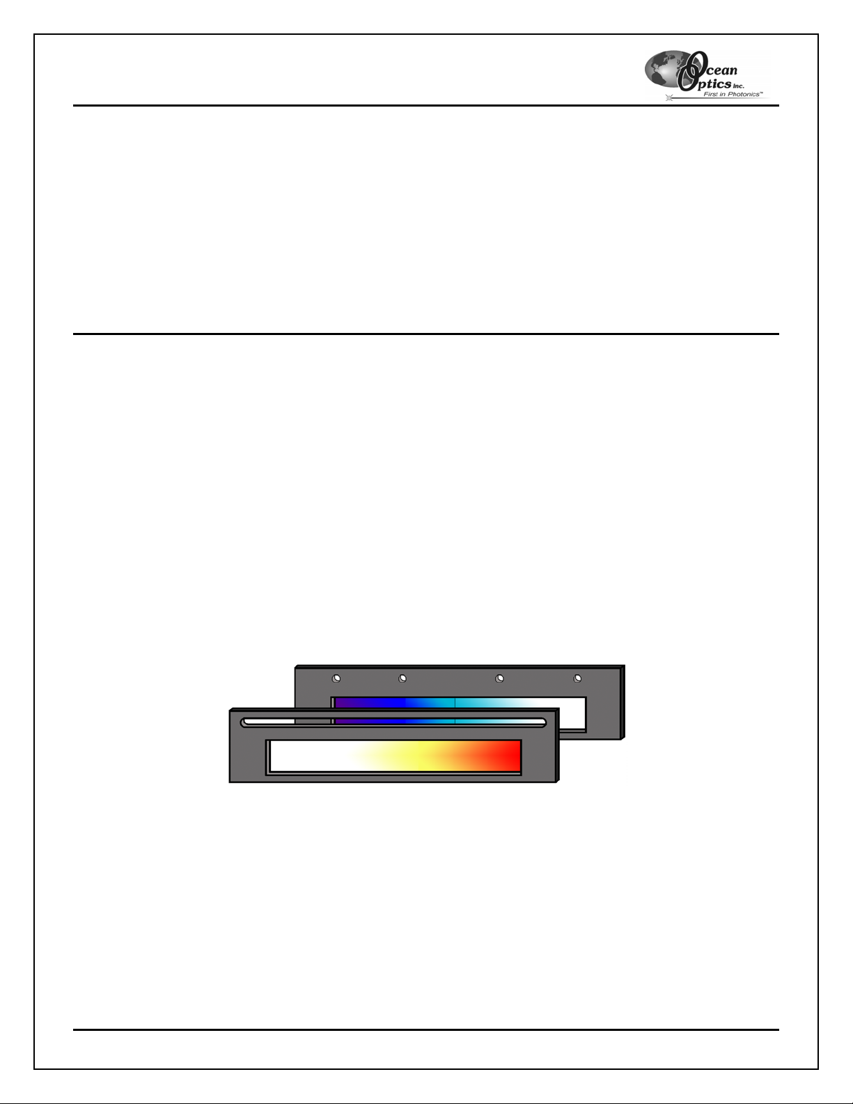
2. Align the filters so that the LVF-H (red) filter is on the top with the red coating on the right side and the
LVF-L (blue) filter is underneath with the blue coating on the left side (see diagram below).
Orientation of Linear Variable Filter slides – Align the LVF-H slide directly over the LVF-L slide as illustrated, then
secure with setscrews
3. Insert each of the four setscrews into the groove in the LVF-H and tighten each screw into the holes on
the LVF-L.
You have now properly assembled the LVF-HL Adjustable Bandpass Filter for use. See the Using the LVF-HL
Adjustable Bandpas s Filter section for operating instructions.
Linear Variable Filters 2
Page 3

Linear Variable Filters
Configuring the Cuvette Adapter (LVF-CUVADPT)
With the LVF-CUVADPT attached, you can still access all openings and setscrews on the original cuvette holder.
To use the Linear Variable Filters with any of the available Ocean Optics 1 cm pathlength cuvette holders, follow
the steps below:
1. Remove the collimating lenses or mirrored screw plugs from the cuvette holder so that the LVFCUVADPT can fit over the existing cuvette holder structure.
2. Align the groove in the filter holder of the existing cuvette holder with the filter groove on the underside of
the LVF-CUVADPT. See the illustration below.
Side View – LVF-CUVADPT connection to an Ocean Optics CUV-ALL-UV 4-way cuvette holder
3. Slide the LVF-CUVADPT down over the existing cuvette holder.
4. Reattach the screw-in attachments through the holes in the sides of the LVF-CUVADPT, securing the unit
to the cuvette holder.
You have now properly attached the Cuve tte Adapter to the cuvette holder.
Configuring the Inline Filter Holder (FHS-LVF)
Designed for use with reflection measurements, the FHS-LVF Inline Filter Holder enables you to easily position
the Linear Variable Filters in your optical path. The FHS-LVF features collimating lenses on each optical input that
focus the light source used in your experiments into a tight, collimated beam.
You need an additional optical patch cord to use the Inline Filter Holder with a reflection probe.
Follow the instructions below to configure the Inline Filter Holder for use with an Ocean Optics reflection probe for
filtering on the excitation side of the fluorescence measurement:
1. Connect an optical patch cord from your light source to one side of the Inline Filter Holder.
2. Connect the illumination leg of the reflection probe (6 fibers) to the other side of the Inline Filter Holder.
3. Connect the detection leg of the reflection probe (1 fiber) to the SMA 905 connector of your spectrometer.
4. Open OOIBase32 and begin to acquire data in scope mode using a white standard.
5. Adjust the collimation lenses on the sides of the Inline Filter Holder until you achieve maximum signal
strength. If necessary, refer to the Collimating Lenses operating instructions located here:
http://www.oceanoptics.com/technical/collimatinglenses.pdf
You have now configured the Inline Filter Holder for use.
Linear Variable Filters 3
Page 4

Linear Variable Filters
Using the Linear Variable Filters
Once you properly configure your LVF-KIT attachments, you can use the Linear Variable Filters themselves.
There are two steps to perform when using Linear Variable Filters (one if you are using the LVF-H or LVF-L
alone).
Follow the instructions in the sections below to properly use the Linear Variable Filters:
Adjusting the Bandpass Width of the Linear Variable Filters
Note: This step only applies if you are using the Adjustable-bandpass Linear Variable Filters (LVF-HL). Proceed
to the next section if you are using the LVF-H or LVF-L by itself.
With the LVF-HL Adjustable-bandpass filters, you can adjust the position of the filters relative to one another to
allow a wider or narrower band of signal to pass through the filters. The LVF-HL is effective in restricting
bandpass to as small as 20 nm, and it can allow a bandpass as large as 100 nm. The filters are shipped preadjusted to a default bandpass width of ~25 nm FWHM.
Follow the steps below to adjust the bandpass of the LVF-HL:
1. Configure your LVF-KIT sampling accessories as described previously in this document.
2. Start OOIBase32 and begin acquiring data in scope mode.
3. Loosen the four setscrews on the LVF-HL slightly until the filters slide from side to side with minimal
resistance. Do NOT over-loosen or remove the setscrews.
4. Insert the LVF-HL into the filter holder in your system.
5. Slide the LVF-H and LVF-L slides of the LVF-HL relative to one another until you obtain the desired
bandpass width. Monitor the signal wid th in OO I Base32 to verify that your adjustm ents are correc t.
6. Secure the setscrews on the LVF-HL to lock the slides in position.
You have now adjusted the bandpass width of the Linear Variable Filter. In the future, repeat these steps to remodify the bandpass width.
Adjusting the Spectral Range of the Linear Variable Filters
You can adjust the position of the LVF-HL to obtain a signal in the desired wavelength range. Follow the
instructions below to make this adjustment.
1. Configure your LVF-KIT sampling accessories as described previously in this document.
2. Start OOIBase32 and begin acquiring data in scope mode.
3. Adjust the bandpass width of the LVF-HL, if necessary (see the Ad jus t ing the Ba ndpass Width of the
Linear Variable Filters instructions above).
4. Insert the LVF-HL slide into the filter holder.
5. Adjust the position of the LVF-HL slide in the filter holder until OOIBase32 displays the desired band.
6. Secure the LVF-HL in place by tightening the setscrews on the top of the Inline Filter Holder or the LVFCUVADPT until the slide is secured.
Note: Do NOT over-tighten the setscrews on the Inline Filter Holder or the LVF-CUVADPT, as this can
damage the LVF slide carrier.
You have now adjusted the spectral range of the Linear Variable Filter.
Linear Variable Filters 4
Page 5

Linear Variable Filters
Using the LVF-H or LVF-L Filters Stand-alone
In situations where you need to restrict an excitation source’s signal above or below a certain wavelength, you
can use the LVF-H highpass or LVF-L lowpass filters individually. These filters will block the signal below a certain
wavelength (highpass) or above a certain wavelength (lowpass).
Follow the instructions below to make this adjustment.
1. Configure your LVF-KIT sampling accessories as described previously in this document.
2. Start OOIBase32 and begin acquiring data in scope mode.
3. Insert the LVF-H or the LVF-L filter slide into the Ocean Optics cuvette holder.
4. Slide the filter slide in the cuvette holder and monitor the OOIBase32 display until the appropriate
wavelength region is blocked.
5. Secure the filter slide in place by tightening the setscrews on the top of the Inline Filter Holder or the LVFCUVADPT until the slide is secured.
Note: Do NOT over-tighten the setscrews on the Inline Filter Holder or the LVF-CUVADPT, as this can
damage the slide carrier.
You have now adjusted the LVF-H or LVF-L for stand-alone use.
Linear Variable Filters 5
 Loading...