

Page 1
LIBS Imaging Module
Installation and Operation Instructions
Description
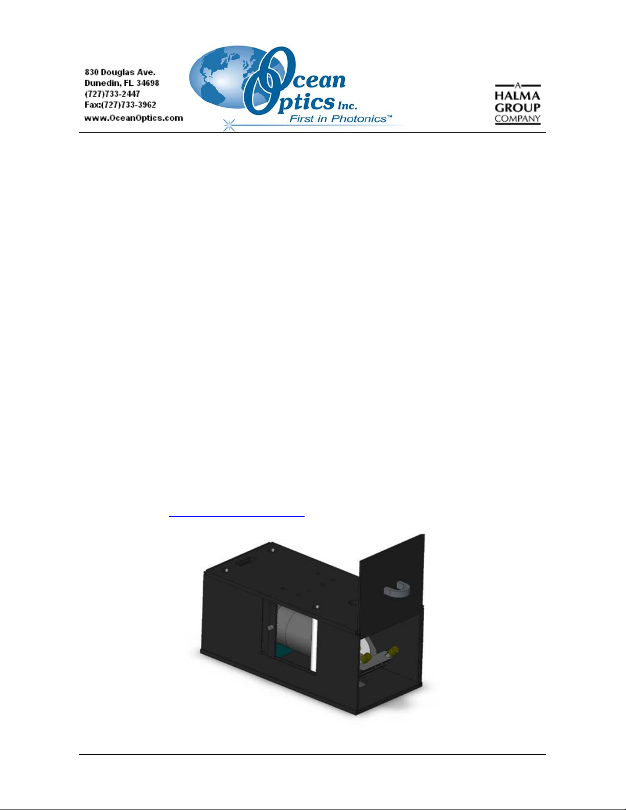
The Ocean Optics LIBS Imaging Module consists of a PixeLINK™ Megapixel FireWire Camera
(black and white or color) in a box mounted in between the LIBS laser and the LIBS Sample Chamber
(LIBS-SC) as they are stacked on top of each other. This product is designed to enable you to
precisely adjust the laser to focus on the exact spot on the sample that you wish to analyze. The LIBS
Imaging Module also comes with PixeLINK software for the camera to capture high quality images on
your PC. The camera is connected to the PC by a single FireWire interface and all camera functions
are controlled by the PixeLINK software. The LIBS Imaging Module was designed to work only with
the LIBS Sample Chamber (LIBS-SC).
Laser-induced Breakdown Spectroscopy (LIBS) is a laser spark analytical technique used to determine
the elemental composition of various solids, liquids and gases. A high-power laser pulse is focused on
to a sample to create a plasma or laser spark. The atoms and ions in the plasma emit light energy that
is collected by a lens or fiber optic cable and analyzed by a time-gated spectrometer. The atomic
spectral lines can be used to determine elemental composition (and concentrations in some systems).
One of the benefits is that little or no sample preparation is required, making the technique fieldportable. Additionally, the system needs only trace amounts of a sample to make measurements, so it’s
a practical tool for scanning applications. For more information about the Ocean Optics LIBS systems,
visit our website at
http://www.oceanoptics.com.
163-00000-000-01-0705 1
Page 2

LIBS Imaging Module Installation and Operation Instructions
Parts Included
The Ocean Optics LIBS Imaging Module ships with the following items:
• LIBS Imaging Module with black and white camera (LIBS-IM) or LIBS Imaging Module
with color camera (LIBS-IM-C)
• LIBS and PixeLINK Software CD
• 12 VDC power supply
• FireWire cable
• Also if purchased – FireWire PCI (LIBS-IM-PCI) or PCMCIA Card (LIBS-IM-PCIA)
Other Required Equipment
• Ocean Optics LIBS Sample Chamber (LIBS-SC)
• Laser – Users can supply their own laser for excitation or can purchase one through Ocean
Optics. We recommend the ULTRA CFR Nd:YAG laser from Big Sky Laser Technologies
www.bigskylaser.com/compactseries.html).
(
• Personal Computer – See the PixeLINK documentation on the LIBS and PixeLINK Software
CD for a list of PC hardware and software requirements
• Spectrometer system
System Requirements
• Microprocessor:
• Minimum – 450 MHz Pentium® III or equivalent
• Recommended – 1.5GHz Pentium® 4 or equivalent
• 128 MB system RAM
• 25 MB hard drive free space
• Video card with 24 or 32 bit True Color graphics
• 8 MB of video memory
• FireWire port or adapter card (available from Ocean Optics)
Installing the Software
► Procedure
To install OOILIBS and PixeLINK software,
1. Close all other applications running on the PC.
2. Start the software installation process.
2 163-00000-000-01-0705
Page 3

LIBS Imaging Module Installation and Operation Instructions
Installing from CD:
a. Insert the LIBS and Pixelink Software CD containing the OOIBase32. The CD interface
automatically launches.
b. Double-click on A6XX SERIES CameraKit R3.2.exe to install the appropriate drivers
and software.
c. Go to the FlashUpdate menu and double-click on the setup.exe file.
Installing from Web:
a. Go to http://www.oceanoptics.com/technical/softwaredownloads.asp.
b. Right-click on PixeLINK Software and select Save Target As… to download the
executable to your machine.
c. Double-click on the downloaded file. The installation process begins.
Installing the Hardware
The LIBS Imaging Module sits on top of the LIBS-SC. The laser mounts to the top of the LIBS
Imaging Module.
Attaching the LIBS Imaging Module to the LIBS Laser
► Procedure
Follow the steps below to attach the LIBS Imaging Module to the bottom of the laser:
1. Insert the mounting rods into the holes in the top of the LIBS Imaging Module. These rods
should pass completely through the LIBS Imaging Module and enter the corresponding holes
in the LIBS Sample Chamber. This assures the alignment of the camera to the sample.
163-00000-000-01-0705 3
Page 4

LIBS Imaging Module Installation and Operation Instructions
2. Insert one end of the FireWire cable through the hole in LIBS Imaging Module cover and plug
it into either FireWire port on the PixeLINK camera. Plug the other end of the cable into the
FireWire port on your PC.
3. Plug in the 12 VDC power supply as shown below. There is no need to open the door of the
LIBS Imaging Module.
4. Insert the laser mounts onto the mounting rods on top of the LIBS Imaging Module and slide
it into position.
4 163-00000-000-01-0705
Page 5

LIBS Imaging Module Installation and Operation Instructions
5. Open the sliding door on the side of the imaging module to adjust the zoom lens. Completely
extending the zoom lens offers the finest resolution.
6. Open the front door of the imaging module to adjust the mirror using its three knobs.
163-00000-000-01-0705 5
Page 6

LIBS Imaging Module Installation and Operation Instructions
Operating the LIBS Imaging Module
► Procedure
1. Focus the image on the screen.
2. Fire the laser at the sample.
3. Adjust the mirror’s three knobs after firing laser at target to ensure that the laser spot is in the
center of the image.
4. Close the front door of the LIBS Imaging Module.
5. Fire the laser.
6. Start your experiments.
Specifications
Specifications Criteria
Physical Dimensions
Weight
Power Consumption 250 mA at 12 VDC (supplied by PC FireWire card)
Sample Image Resolution:
Black and white camera
Color camera
Operating Temperature +5o to +60oC
Camera Specifications:
Resolution
Pixel Size
Frame Rate
305 mm x 146 mm x 127 mm
3.68 kg
40 microns
60 microns
1280 x 1024 active pixels
6.0 um x 6.0 um, square
Up to 12.7 fps at 180 x 1024 resolution
6 163-00000-000-01-0705
 Loading...