

Oakley SRE330 Owner's Manual

Oakley Sound Systems
Stereo Ensemble – SRE330
Main Board Issue 2
Builder's Guide
V2.10
Tony Allgood
Oakley Sound Systems
CARLISLE
United Kingdom
Introduction
This is the Builder's Guide for the Stereo Ensemble Module SRE330 from Oakley Sound. This
document contains a basic introduction to the three circuit boards used to make the SRE330 rack
module and a full parts list for all the components needed to populate the board or boards.
For the User Manual, which contains an overview of the unit, the operation of the module and the
calibration procedure, please visit the main project webpage at:
http://www.oakleysound.com/sre330.htm
For general information regarding where to get parts and suggested part numbers please see our
useful Parts Guide at the project webpage or http://www.oakleysound.com/parts.pdf.
For general information on how to build our modules, including circuit board population, mounting
front panel components and making up board interconnects please see our generic Construction
Guide at the project webpage or http://www.oakleysound.com/construct.pdf.
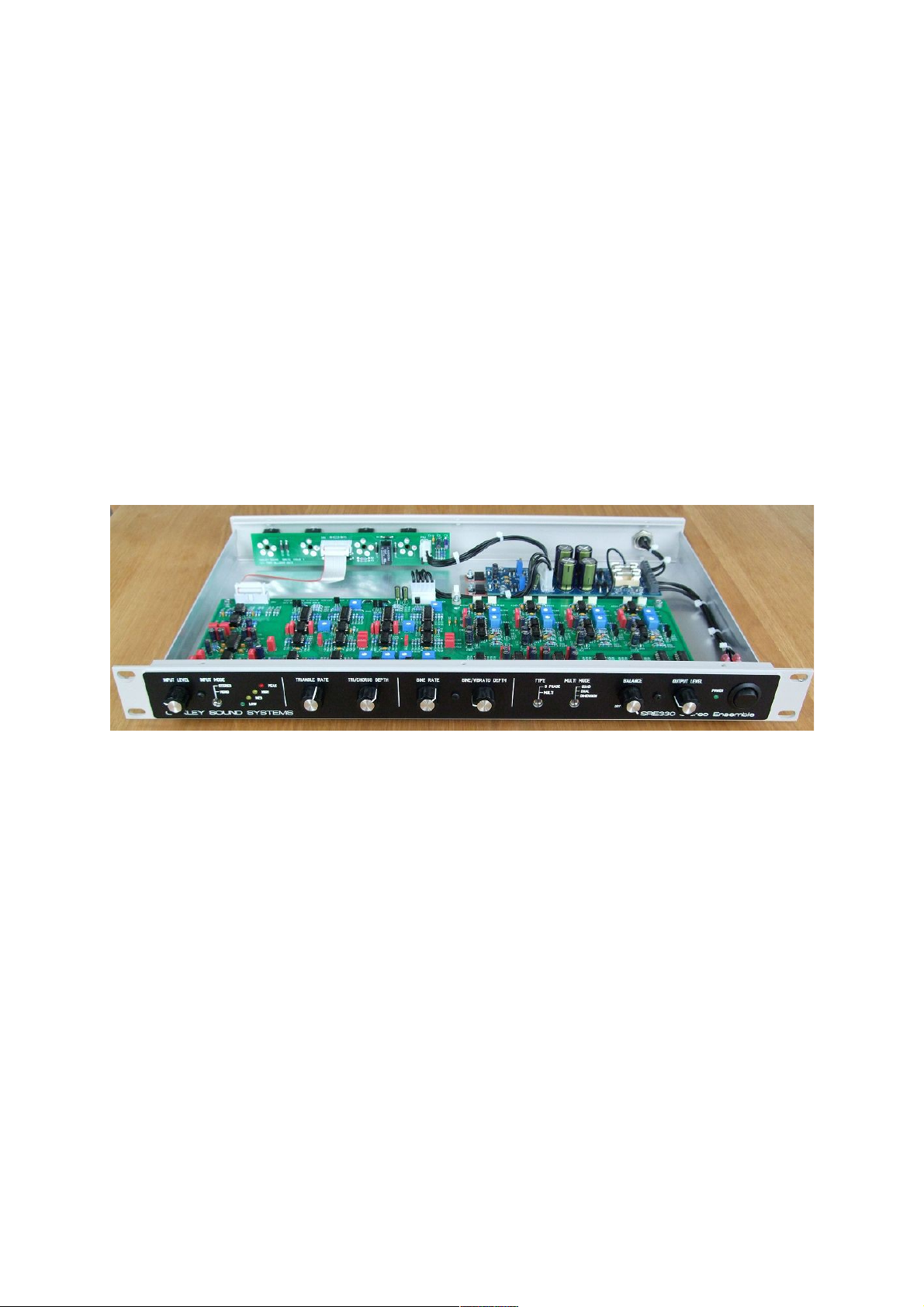
The first prototype unit built into a Bryant Broadcast 1U 250mm deep 19” rack enclosure with the Schaeffer front
panel attached. This one used an earlier issue 1 RPSU power module. Issue 2 RPSU boards are green and use a
five way 0.156” connector to take power onto the SRE330 main board.
Constructing the SRE330
The SRE330 project uses the SRE330 main board, the optional SREIO input/output board and the
RPSU +/-15V power supply module.
The SRE330 main board requires a well regulated and quiet +/-15V to +/-16V supply. The current
taken by the SRE330 varies slightly with modulation depth but the maximum current is around
+225mA and -180mA. Power is admitted onto the main board via a 5-way Molex 0.156” KK or 5way 0.156” MTA connector. Pin 1 is +15V, pin 2 and 3 are 0V, pin 4 is -15V and pin 5 is panel
ground. Panel ground is typically connected to 0V at either the power supply or the input/output
sockets. On the SRE330 main board Pin 5 connects only to the pot brackets and switches' metal
supporting tangs.
The SRE330 is a large board at 389mm wide and 153mm deep. It is secured to the front panel by
the pot brackets and to the lower panel of the case with three M3 screws and spacers. The board has
four copper layers, the top and bottom copper layers carry signals, the top middle layer carries
power supplies and some signals, and the bottom middle layer is solely designated to 0V. A four
layer design, although expensive to produce, gives better performance than standard two layer
board designs. It is, however, imperative that when soldering, and especially desoldering, that the
through hole plating used to line all the solder pad holes is not damaged. If you do need to desolder
a part then either use a proper vacuum desoldering tool or cut the component body out first and then
desolder one component leg at a time.
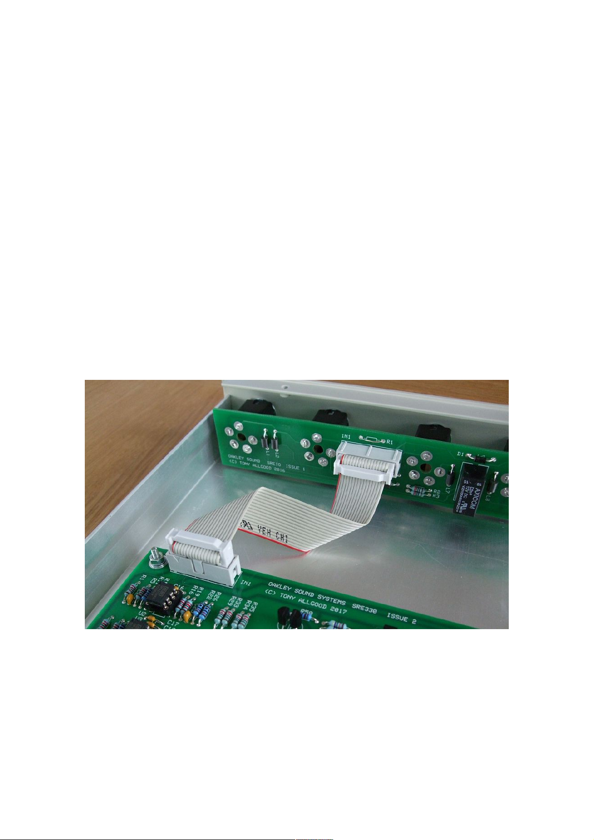
The 16-way ribbon cable used to transfer the balanced audio signals between the SRE330 main board and the
SREIO socket board.
The SREIO board is an input and output socket board designed for this project. It allows the simple
interconnection between the SRE330 main board and the audio sockets via a single 16-way 0.05”
IDC ribbon cable. The SREIO board also features a electromechanical relay to cut the connection
between the main board's output circuitry and the output sockets at power on and power off. This
reduces the likelihood of damaging thumps on the audio output when power is turned on and off.
The anti-thump circuitry is powered from the main power supply module via a three way 0.156”
Molex or MTA connector. Pin 1 is +15V and pin 3 is 0V. Pin 2 can be used to 'ground' the sockets'

earth lug to the power supply's 0V if desired although this is not normally needed in most SRE330
builds.
The relay and power muting circuitry on the SREIO board.
The SREIO board is 34mm high and 185mm wide. It is a two layer design. The sockets used are the
industry standard 1/4” TRS (Tip Ring Sleeve) socket, the Switchcraft 114BCPX. Various clones of
this socket are available but arguably Switchcraft still make the best version.
The RPSU is a power supply module designed specifically for the SRE330, although it is likely that
other future Oakley Sound rack projects will use this module too. It generates +/-15.3V at up to
around 1A given sufficient heatsinks and a suitable mains transformer. The SRE330 only needs less
than 250mA but even so adequate heatsinking must be used for the two power devices. Since best
performance for any electronic audio device comes from using a metal case it makes sense to use
the case itself as a heatsink. Details on how to do this are given later in this document.
The issue 2 RPSU wired for use with a Yamaha PA-20 external power supply.
Although the RPSU can be used with an internal mains transformer, I recommend that builders use
an external low voltage output line lump or wallwart type mains adapter. This keeps all the high
voltages away from your project and ensures your safety. An example of such is the Yamaha PA-20
which is available from all larger music stores. Later on in this document I will give details on how
to build your RPSU module to suit your chosen method of supplying power.
The RPSU is 150mm by 51mm in size. It is a two layer board and made from double thickness
copper to reduce unwanted voltage drops along the copper traces on the board. Unlike the issue 1
RPSU board there are no trimmers to set the voltages to exactly +/-15.00V. The SRE330 main
board's circuitry is not bothered whether the voltage is exactly 15.00V but only that it doesn't
change once the SRE330 main board has been calibrated. The RPSU board thus needs no trimmers
and produces a little over +/-15.3V when built as recommended.
The RPSU requires an AC supply of a minimum of 15V to work correctly. When used with a centre
tapped AC supply, such as that from the PA20 or internal mains transformer, the current taken is
approximately 0.4A (RMS). With a single phase supply, such as that from a standard AC output
wallwart supply, the current required will be in the order of 0.7A (RMS).
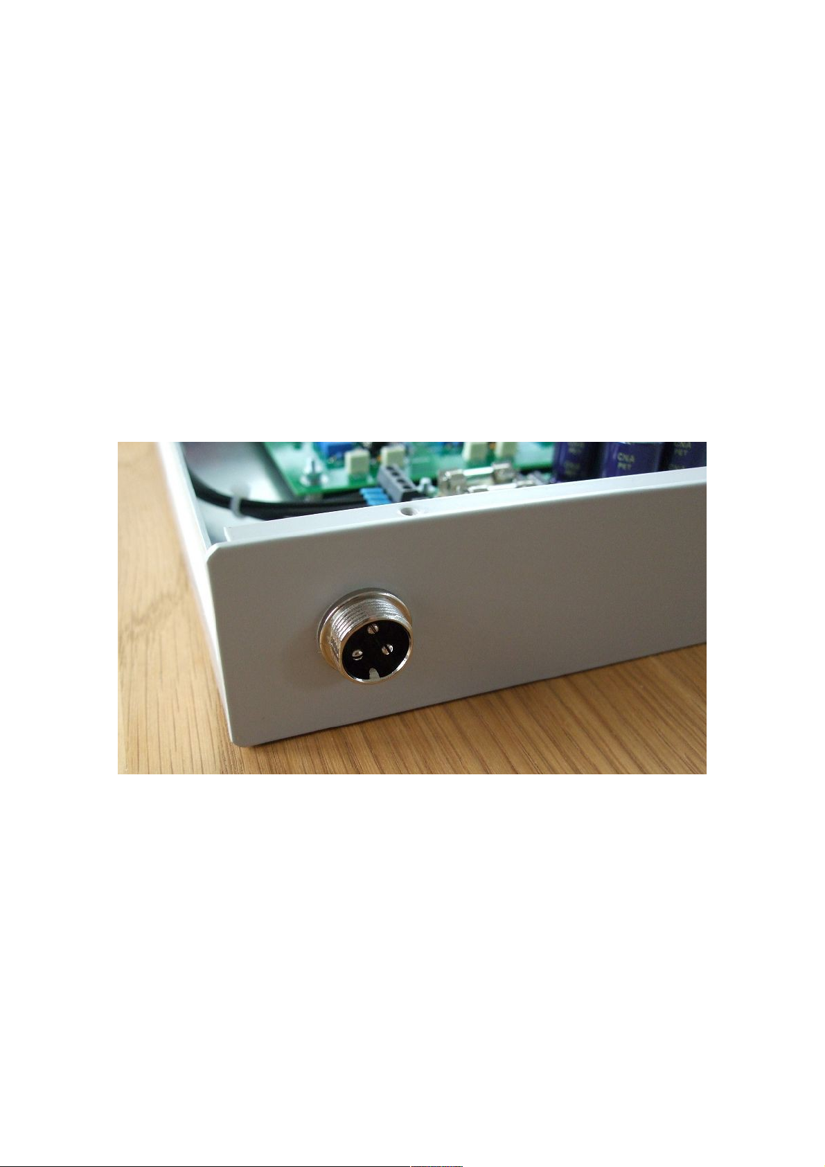
The three way power socket that will fit the Yamaha PA20 power supply.

Parts Lists
For general information regarding where to get parts and suggested part numbers please see our
useful Parts Guide at the project webpage or directly from http://www.oakleysound.com/parts.pdf.
The components are grouped into values, the order of the component names is of no particular
consequence. Component values given in this list supersede those shown on the schematic.
A quick note on European part descriptions. R is shorthand for ohm. K is shorthand for kilo-ohm.
So 22R is 22 ohm, 1K5 is 1,500 ohms or 1.5 kilohms. For capacitors: 1uF = one microfarad =
1000nF = one thousand nanofarad.
To prevent loss of the small ‘.’ as the decimal point, a convention of inserting the unit in its place is
used. eg. 4R7 is a 4.7 ohm, 4K7 is a 4,700 ohm resistor, 6n8 is a 6.8 nF capacitor.
SRE330 Main Board issue 2 Parts List
Resistors
All resistors should be 1% 0.25W metal film resistors except for R57 which can be 5% metal film
or carbon.
22R R40
75R R37, R36, R203, R257, R181, R227
120R R38, R39, R52
220R R34, R33, R29, R35
390R R151, R91, R87, R139, R136, R148, R78, R84, R53
510R R54
1K R56
2K2 R44
3K3 R200, R254, R224, R260, R178
3K9 R4, R24
4K7 R119, R162, R238, R189, R60, R211
6K8 R186, R121, R50, R108, R164, R191, R165, R62, R214, R51, R240, R107
10K R26, R14, R198, R13, R22, R184, R11, R12, R41, R95, R177, R43, R182,
R82, R167, R223, R176, R68, R190, R205, R222, R253, R199, R27, R196,
R23, R252, R83, R67, R71
11K R174, R220, R251, R185, R166, R197
15K R127, R175, R21, R66, R134, R231, R152, R90, R163, R76, R131, R70,
R98, R3, R103, R137, R135, R77, R244, R160, R45
22K R2, R6, R86, R20, R19, R16, R75, R132, R89, R17, R28, R155, R5, R94,
R74, R1, R73, R81, R97
30K R173, R172
33K R217, R256, R79, R246, R92, R242, R193, R250, R169, R180, R259, R15,
R55, R25, R202, R234, R226
36K R249, R261
39K R221, R239
47K R208, R209, R63, R122, R30, R216, R31, R245, R8, R18, R42, R192, R64,
R109, R49, R124, R7, R154, R48, R105, R158, R168, R207, R157, R150, R9

51K R235, R229, R228, R243, R241, R233, R212, R215
56K R123, R102, R141, R113, R32, R10
100K R218, R46, R183, R128, R247, R69, R100, R99, R187, R111, R213, R236,
R248, R204, R219, R230, R130, R147, R145, R195, R194, R159, R142,
R171, R170, R206, R116, R232, R258
120K R161, R106, R125, R237, R188, R65, R47, R210
150K R225, R255, R201, R179
330K R110, R129, R104, R146
390K R144, R112, R149, R153, R156, R114
470K R138, R115, R61, R133, R58, R59, R126, R140, R143, R120, R117, R118,
R101
820K R88, R93, R96
1M R72, R80, R85
3M3 R57
Capacitors
10pF C0G 2.5mm ceramic C14, C28
22pF C0G 2.5mm ceramic C8, C21
33pF C0G 2.5mm ceramic C169, C184, C195, C190
56pF C0G 2.5mm ceramic C181, C122, C92, C155
100pF C0G 2.5mm ceramic C25, C166, C52, C26, C138, C80, C189, C57, C2, C103, C3,
C75
220pF C0G 2.5mm ceramic C112, C20, C29, C102, C27, C142, C165, C113, C101, C137,
C121, C15, C188, C136
1nF C0G 2.5mm ceramic C93, C182, C156, C123
1n5 100V polyester C158, C97, C117, C185, C91, C128
2n2 100V polyester C139, C191, C111, C100, C167, C106
10nF 63V polyester C41
22nF 63V polyester C140, C192, C168, C84, C107
47nF 63V polyester C72, C82, C83
100nF 63V polyester C40, C60, C62
220nF 63V polyester C51, C58, C59
470nF 63V polyester C86, C172, C151, C87, C61, C150, C171, C116, C115, C70,
C50, C43
1uF 63V polyester C9, C5, C1, C149, C37, C131, C108, C39, C146, C143, C148,
C125, C32, C147
2u2 50V polyester C4, C10, C170, C180
100nF axial multilayer ceramic C68, C67, C76, C66, C187, C35, C63, C73, C53, C46, C54,
C79, C164, C56, C129, C193, C96, C95, C160, C176, C99,
C98, C183, C162, C130, C94, C77, C174, C78, C159, C44,
C124, C194, C45, C47, C186, C16, C18, C19, C17, C114,
C64, C22, C81, C85, C48, C13, C105, C24, C49, C12, C23,
C104, C141, C161, C36, C65, C55, C74, C175, C173, C163,
C157
2u2, 63V electrolytic C178, C177, C152, C88, C153, C89, C118, C31, C119

4u7, 50V electrolytic C109, C110, C30, C33, C144, C126, C145, C133, C132, C6,
C11, C127
10uF, 35V electrolytic C7, C135, C69, C71, C42, C134, C34
47uF, 35V electrolytic C154, C120, C90, C179, C38
Integrated Circuits
TL072CP dual FET op-amp U47, U20, U45, U6, U13, U10, U25, U37, U42, U50, U21,
U27, U14, U15, U26, U18, U9, U8, U31, U54, U22
OPA2134PA dual op-amp U48, U46, U3, U2, U1
NE5532AP dual audio op-amp U30, U34, U5
V571D or NE570 compander U35, U40, U4
V3102D BBD driver U44, U39, U52, U33
V3207D BBD U51, U32, U38, U43
LM13700N dual OTA U12, U24, U7, U19
LM2901N quad comparator U11
DG403DJ dual analogue switch U55, U23, U16, U17, U53, U28
78L09 +9V regulator 100mA U29, U36, U41, U49
The Belling BL3207 or Panasonic MN3207 may be used instead of the Coolaudio V3207.
IC sockets are recommended for the V571D, V3102D, V3207D and LM13700N even if you don't
socket any of the other ICs.
Discrete Semiconductors
BC550 NPN transistor Q9, Q8, Q14, Q10, Q15, Q12, Q13, Q11
BC560 PNP transistor Q5, Q7, Q4, Q6, Q3, Q2, Q1
1N4148 signal diode D16, D22, D24, D10, D25, D23, D20, D26, D18, D19, D15,
D11, D6, D12, D7, D21, D9, D17
1N5819 diode D13, D14
BZX55C2V7 2V7 zener diode D1, D2, D3, D4
BAT42 Schottky diode D5, D8
3 mm red LED PK
3 mm yellow LED HI, MD
3 mm green LED LO, ON
Trimmers
All trimmers are 6mm types. For example, Bourns 3386F.
5K NULL1, NULL2, NULL3, NULL4
20K T_LVL, S_LVL
50K FAST, SLOW, OFF1, OFF2, OFF3, OFF4
100K S_FRQ, T_FRQ, CLK1, CLK2, CLK3, CLK4

Pots
All pots 16mm Alpha or Alps types.
50K linear TRI_RATE, SIN_RATE
50K logarithmic TRI_DEPTH, SIN_DEPTH
50K dual gang linear OUT_LEVEL, BALANCE, INPUT
Seven Alpha pot brackets. Seven knobs to suit.
Switches
SPDT ON-OFF-ON toggle switch MODE
SPDT ON-ON toggle switch TYPE, MONO
Interconnects
5 way Molex 0.156” header POWER
16 way 2 x 8 IDC box header* IN1
* If choosing to hand wire the sockets rather than using the optional SRIO board then you do not
need to fit this IDC header. Instead you will wire the sockets to the appropriate solder pads where
the header would normally be fitted.
Miscellaneous
Mounting hardware for the three mounting holes. For the Bryant Broadcast or Holt Broadcast 1U
aluminium cases the following hardware can be used.
M3 hex threaded 6mm spacers (3 off)
M3 CSK 16mm screws (3 off)
M3 hex nut (3 off)
M3 shakeproof washers (6 off)
M3 flat washers (3 off)
The shakeproof washers go between the bottom panel and the hex spacer, and between the flat
washer and the top nut. The flat washer goes up against the top surface of the PCB.
 Loading...