

Oakley RM-4014 Owner's Manual

Oakley Sound Systems
Oakley Modular Eurorack Series
RM-4014 Ring Modulator
PCB Issue 3E
Builder's Guide
V3.1.0
Tony Allgood
Oakley Sound Systems
CARLISLE
United Kingdom

Introduction
This is the Project Builder's Guide for the issue 3E RM-4014 Ring Modulator Euro module
from Oakley Sound. This document contains a basic introduction to the board, a full parts list
for the components needed to populate the board, a circuit description, and a list of the
various interconnections.
For the User Manual, which contains an overview of the operation of the unit and the
calibration procedure, please visit the main project web page at:
http://www.oakleysound.com/ringmod-e.htm
For general information regarding where to get parts and suggested part numbers please see
our useful Parts Guide at the project webpage or http://www.oakleysound.com/parts.pdf.
For general information on how to build our modules, including circuit board population,
mounting front panel components and making up board interconnects please see our generic
Construction Guide at the project web page or http://www.oakleysound.com/construct.pdf.
2
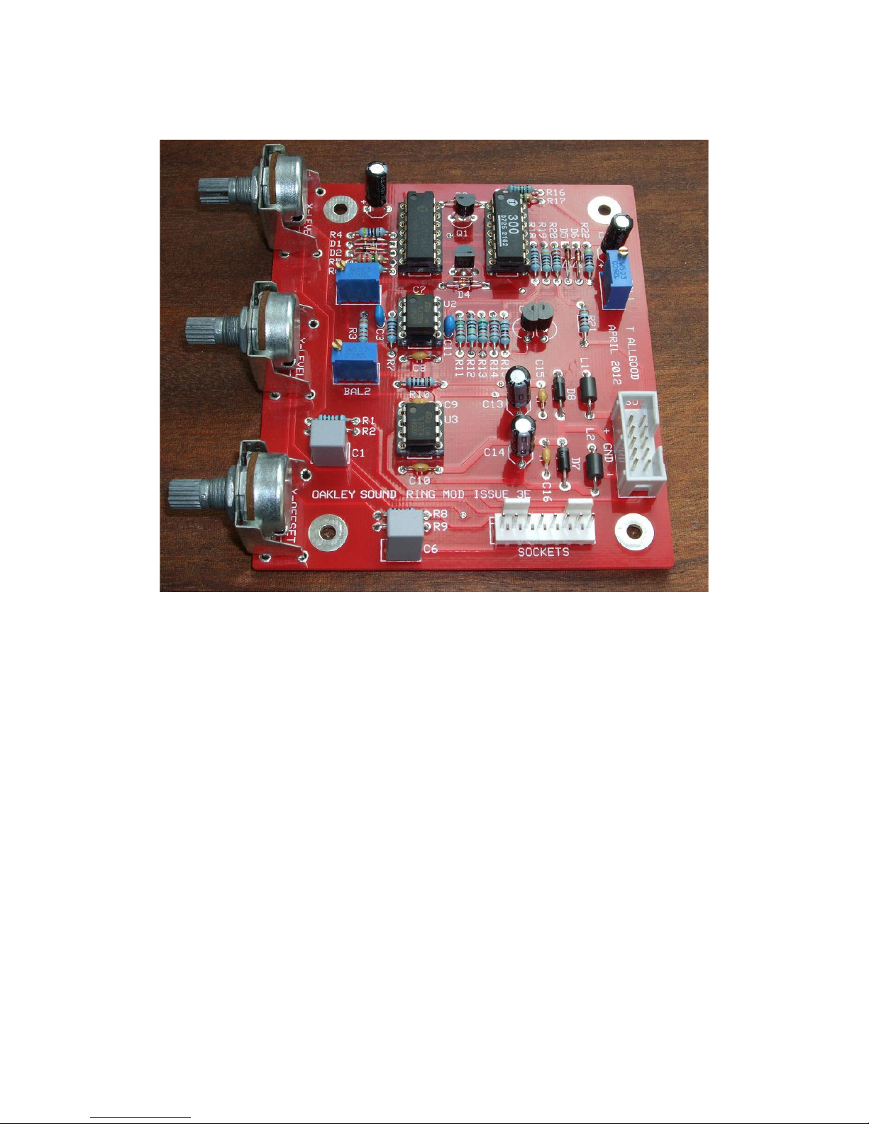
The Issue 3E Ring Modulator PCB
This is the issue 3E Euro sized Ring Modulator board fully populated and awaiting panel mounting and
sockets wiring.
This is one of our smaller format PCBs. The module is designed to fit into a Euro rack. The
pots are Alpha/ALPS 16mm types with matching brackets.
The module requires plus and minus 12V supplies. The power supply should be adequately
regulated. The current consumption is about +/-38 mA. Power is routed onto the main PCB
via the usual 2 x 5 way 0.1” (2.54mm) header for compatibility with Euro format modular
systems. The top pins on the header are connected to the +12V supply. Reverse polarity
protection diodes have been fitted although these should not be relied upon to protect your
module for a long period of time.
The PCB has four mounting holes for M3 bolts, one near each corner. These are not required
if you are using our specially made pot brackets. The size of the board is 96.5mm high by
86.4mm deep.
The input and output sockets are wired to the board via an eight way 0.1” Molex or MTA
interconnect.
3

Ring Modulator issue 3E Parts List
For general information regarding where to get parts and suggested part numbers please see
our useful Parts Guide at the project web page or http://www.oakleysound.com/parts.pdf.
The components are grouped into values, the order of the component names is of no particular
consequence.
A quick note on European part descriptions. R is shorthand for ohm. K is shorthand for kiloohm. R is shorthand for ohm. So 22R is 22 ohm, 1K5 is 1,500 ohms or 1.5 kilohms. For
capacitors: 1uF = one microfarad = 1000nF = one thousand nanofarad.
To prevent loss of the small ‘.’ as the decimal point, a convention of inserting the unit in its
place is used. eg. 4R7 is a 4.7 ohm, 4K7 is a 4700 ohm resistor, 6n8 is a 6.8 nF capacitor.
Resistors
All 5% carbon 1/4W or better, except where stated.
220R R20
470R R19
680R R6, R16
1K R10
4K7 R22, R4
10K R9, R1, R2, R8
12K R14
15K R11
18K R7, R15, R18
39K R3, R21
56K R13
1M R12
2M2 R5, R17
Capacitors
15pF 2.5mm C0G ceramic C11
47pF 2.5mm C0G ceramic C3
100nF axial multilayer ceramic C7, C8, C9, C10, C15, C16
1.5uF or 2u2, 63V or 50V polyester C1, C6
2.2uF, 25V electrolytic C4, C17, C13, C14
4

Discrete Semiconductors
1N4004 rectifier diode D7, D8
1N4148 signal diode D1, D2, D3, D4, D5, D6
BC550 NPN transistor Q2, Q4
BC560 PNP transistor Q1, Q3
Integrated Circuits
TL072 dual op-amp U2, U3
THAT320P PNP array U1
THAT300P NPN array U4
Variable Resistors
50K or 100K multiturn trimmer BAL1, BAL2, GAIN
100K linear Alpha 16mm pot X-LEVEL, Y-LEVEL
50K linear Alpha 16mm pot Y-OFFSET
Pot brackets Three off
Miscellaneous
Leaded ferrite beads L1, L2
2 x 5 (10-way) 0.1” box header PSU
0.1” 8-way Molex or MTA header SOCKETS – board mounted
0.1” 8-way Molex or MTA housing SOCKETS – wire harness
DIL14 pin IC sockets Two off
DIL 8 pin IC sockets Two off
Other Parts Required
3.5mm sockets Five off mounted on panel
Three 20mm knobs.
Around 2m of insulated multistrand hook up wire for the socket connections.
5
 Loading...