

Page 1

Quick Start Guide
TWR-P1025
QorIQ Processor with Networking and
Industrial Connectivity and
Protocol Offload Engine
TOWER SYSTEM
Page 2
2
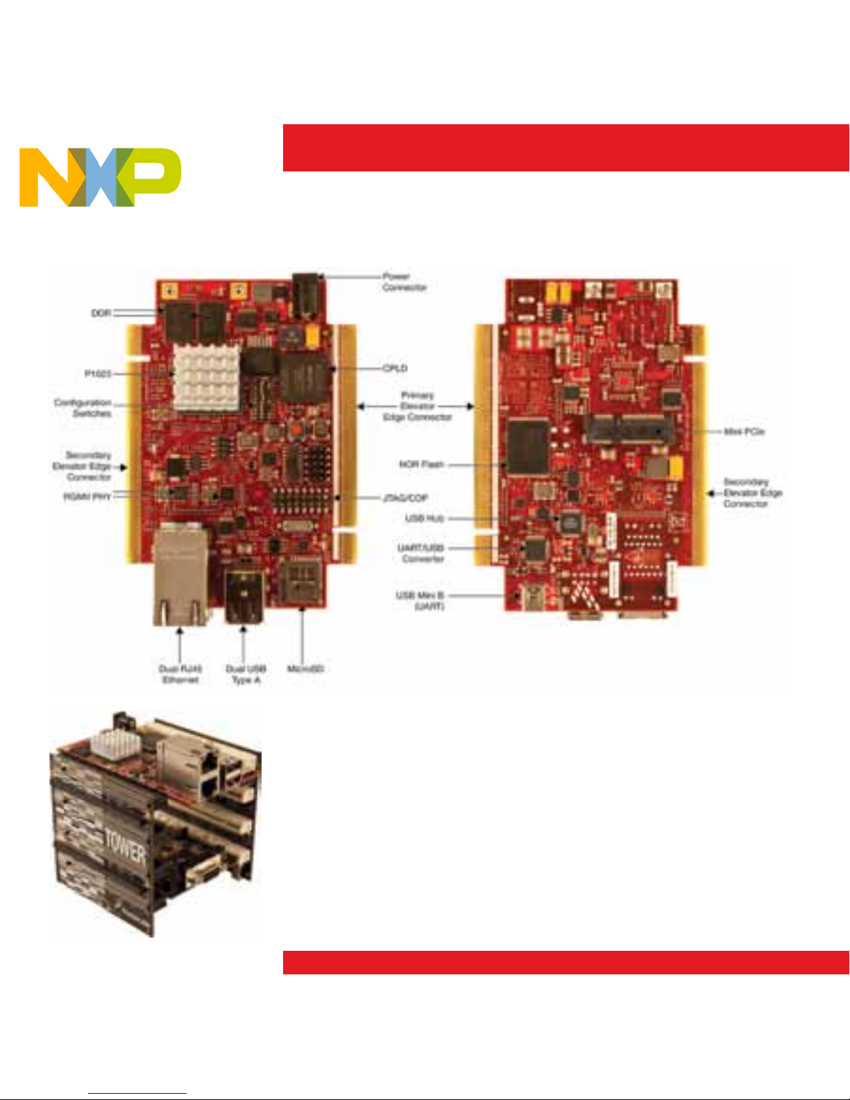
Get to Know the TWR-P1025
TWR-P1025
Freescale Tower System
The TWR-P1025 module is part of the Freescale Tower System
portfolio, a modular development platform that enables rapid
prototyping and tool re-use through reconfigurable hardware.
Elevate your design to the next level by building your Tower
System today.
Quick Start Guide
Page 3

The TWR-P1025 processor module can be operated as a stand-alone
single board computer (SBC) or a Tower System rapid prototyping
development platform. Freescale’s MQX™ real-time OS (shipped
separately) support enables applications to quickly migrate from
Freescale MCUs up to the high-performance QorIQ P1025 processor
featuring networking and industrial connectivity. The P1025 also features
a protocol offload engine which eliminates the need for an external
industrial protocol FPGA/ASIC in the system.
Pre-Loaded Software
• U-bootbootloader
• FreescaleLinux
®
OS with real-time patches
• Diagnosticroutinestovalidateboardfunctionality
TWR-P1025
Page 4

4
Connect a Display
(Optional)
Purchase and connect the TWR-ELEV
modules and TWR-LCD display module to
see a short video on example applications
included with the TWR-P1025. See
the TWR-LCD quick start guide for
assembly instructions. The SW1 Dip[1:3]
switches should be set to [ON, OFF, ON],
respectively. The remaining dip switches
should be at their default setting.
After applying power, wait one minute for
the video to begin.
Powering
TWR-P1025
Connect the 5-volt @5A power supply to
the 5-volt barrel connector on the TWRP1025 module. Note that the heatsink on
the TWR-P1025 can become hot. This is
normal.
Configuring a
Terminal Application
for the Console
On-board circuitry has been provided to
support a host computer console window
over the mini type B USB connector.
Users should note that USB drivers should
be installed onto the host PC before the
serial terminal can be used. These can be
downloaded from ftdichip.com/Drivers/
VCP.htm (FT2232).
Plug in the USB cable between the mini
type B USB connector on the board and
your PC. Do not bend the cable once it
has been inserted. Your PC will assign two
COM port numbers to the USB serial ports
after the driver is installed.
Step-by-Step Installation Instructions
In this quick start guide, you will learn how to set up the TWR-P1025 module and run
the included demonstration software. For more detailed information, please see the
user manual found on the included DVD or at freescale.com/TWR-P1025.
1
2
3
Quick Start Guide
Page 5

TOWER SYSTEM
5
Open a serial console using any terminal
emulation application attached to the lower
numbered COM port with the following
serial protocol settings: Bits per Second:
115200, Data Bits: 8, Parity: None, Stop
Bits: 1, Flow Control: None. See the user
manual for more details.
Connecting
Cables
Dual Ethernet and RS485 ports enable
point-to-point networking demos on a
single TWR-P1025 module. Any Ethernet
cable can be connected between the
Ethernet ports and the ports will autoconfigure for proper communication. Autoconfigure also enables a direct connection
from either Ethernet port to a host
computer Ethernet port. All TWR-P1025
headers have pin 1 marked with a white
dot printed on the board and increasing
pin numbers proceeding top to bottom,
right to left from pin 1 while looking into
the header pins.
For cable connections on other interfaces,
refer to the user manual.
Controlling
the Board
Upon power-up, you can also hit any key
on a connected serial terminal to get to
the u-boot prompt, otherwise the board
will boot to the Freescale Linux OS.
You can also log in to the module via
the OpenWRT interface by opening your
browser to 192.168.1.1 (you will need to
connect your PC LAN port to the module’s
Eth0 port and reconfigure your PC IP
address to 198.168.1.54). The OpenWRT
interface will allow for easy configuration
of the module’s network settings. Use the
following information to log in:
Login: root
Password: root
Standard u-boot and Linux commands are
supported.
5
4
Page 6

6
Debugger Interface
Connections
When the board is powered off, connect
the desired debugger hardware to the
standard JTAG/COP header connector
J3 lining up pin 1. TWR-P1025 includes
on-board debugging circuitry to support
CodeWarrior software to work with the
board.
Configuration
Switch Settings
See configuration switch settings on the
following page.
6 7
Quick Start Guide
Page 7

TOWER SYSTEM
7
SW
1
Signals
2
Settings
2
Switch
3
Description
1 Reserved
0
ON
Reserved
1 OFF
2 PCIE_HOST_AGENT
0 ON PCIe Agent Mode
1 OFF PCIe Host Mode
3 Reserved
0 ON
Reserved
1 OFF
4 CFG_CPU0_1_BOOT
0 ON Core0 boots, Core1 is in holdoff mode after reset
1 OFF Both cores run after reset
5 BOOT_SEQ
1 ON Boot sequencer is OFF
1 OFF Boot sequencer is ON
6 LOCALBUS_QE_MUXSEL
0
ON
LB pins muxed with QE function as QE pins in CPLD
1 OFF LB pins muxed with QE function as LB pins in CPLD
7, 8 CPU_SPEED_SELECT[0:1]
00 ON, ON 533 MHz core, 266 MHz QE, 66.667 MHz SYSCLK
01 ON, OFF Reserved
10 OFF, ON Reserved
11 OFF, OFF Reserved
9 ETH_TDM_SEL
0 ON TDM clock is routed to the P1025 thru the CPLD
1 OFF
Eth1 clock is routed to the P1025 thru the CPLD
10 Reserved
0 ON
Reserved
1 OFF
1) Switch positions as printed on the switch
2) Schematic signal settings readable from software from MSB (top-left as bit 0) to LSB (bottom-right as bit 7)
3) Switch settings as printed on the switch, factory settings highlighted red
ON
Setting
Label
Switch
Position
Label
Configuration
Switch Settings
Page 8

For more information, visit freescale.com/Tower
Join the online Tower community at towergeeks.org
Freescale, the Freescale logo, CodeWarrior and QorIQ
are trademarks of FreescaleSemiconductor,Inc., Reg. U.S.
Pat. & Tm. Off. The Power Architecture and Power.org word
marks and the Power and Power.org logos and related marks
are trademarks and service marks licensed by Power.org.
All other product or service names are the property of their
respective owners. ©2012FreescaleSemiconductor,Inc.
DocumentNumber:P1025TWRQSGREV1
AgileNumber:926-27216REVB
Quick Start Guide
Visit freescale.com/TWR-P1025 for the latest
information on the TWR-P1025 module, including:
• Boarddatabase:Schematics,layoutandBOM
• Usermanual
• Quickstartguide
• SoftwareBSPs,industrialprotocolevaluationstacks
and CodeWarrior
• Demosandtutorial
• Factsheet
Support
Visit freescale.com/support for a list of phone
numbers within your region.
Warranty
Visit freescale.com/warranty for complete
warranty information.
 Loading...