

Page 1
IAR KickStart Kit
Quick Start Guide
For the Freescale Kinetis K60
family of microcontrollers
Tower System
Development Board
Platform
Page 2
2
Quick Start Guide
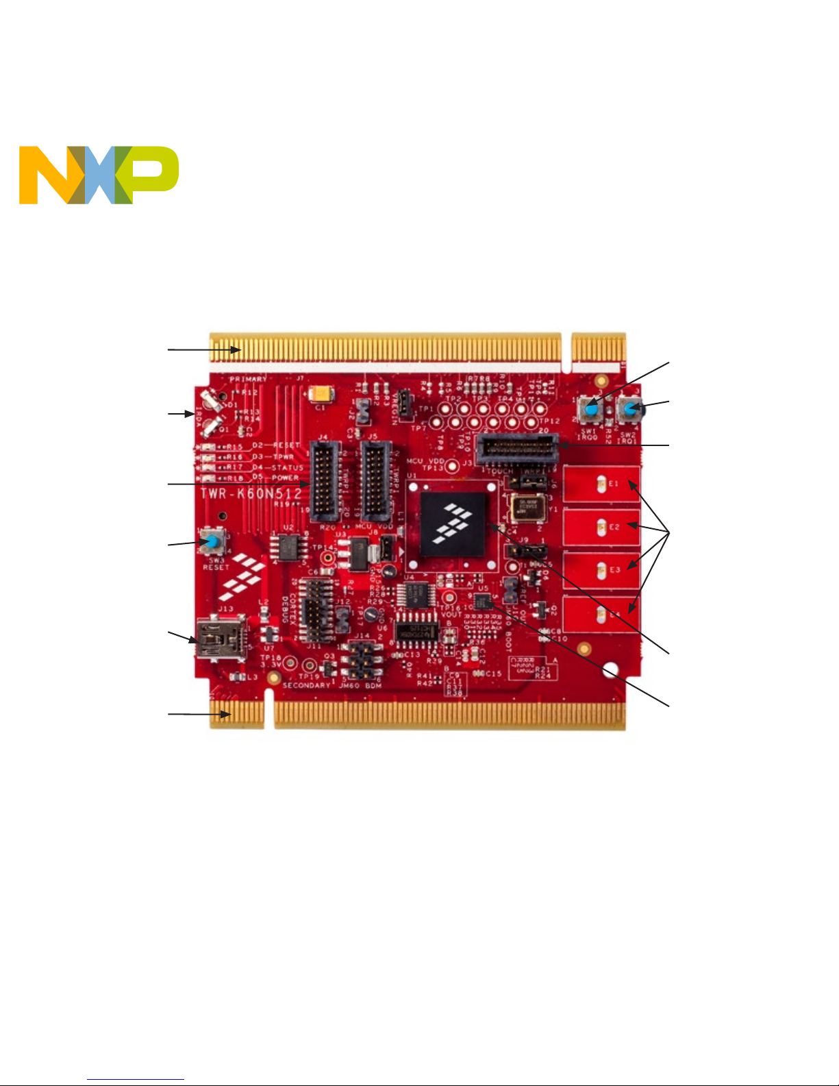
Get to Know the TWR-K60N512-IAR
Primary
Connector
Infra-Red
General-Purpose
Tower Plug-In
(TWRPI) Socket
SW3 (Reset)
Power/OSJTAG
Mini-B USB
Connector
Secondary
Connector
SW1
SW2
Touch TWRPI
Socket
LED/Touch
Buttons
E1–E4
MK60N512
VMD100
Microcontroller
MMA7660
Accelerometer
Figure 1: Front Side of TWR-K60N512 Board Not Including TWRPI
Page 3
3
freescale.com
TWR-K60N512
Freescale Tower System
Development Board Platform
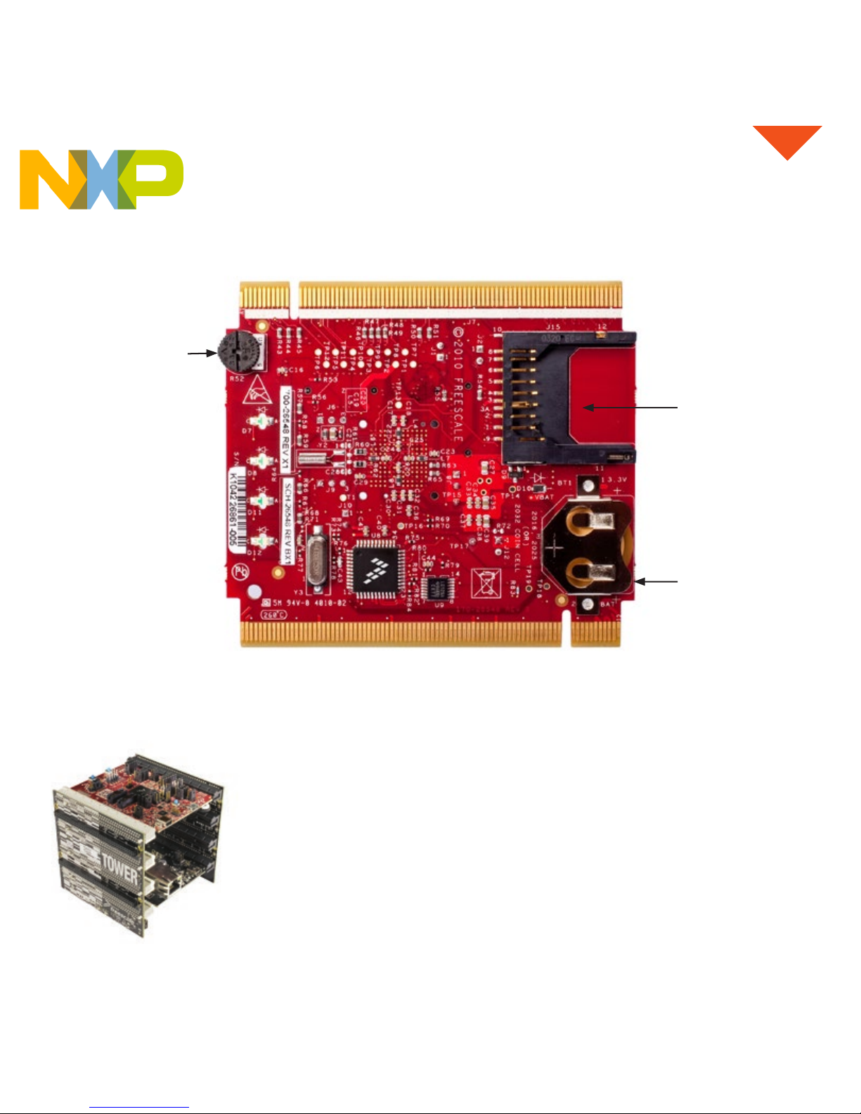
The TWR-K60N512 board is part of the Freescale Tower System, a
modular development board platform that enables rapid prototyping
and tool re-use through reconfigurable hardware. Take your design to
the next level and begin constructing your Tower System evaluation
board platform today by visiting freescale.com/Tower.
Potentiometer
Figure 2: Back Side of TWR-K60N512 Board
SD Card
Socket
VBAT (RTC)
Battery
Holder
Page 4

This guide briefly describes how to get
started using IAR Embedded Workbench®
with IAR J-Link (Lite), USB-JTAG/SWD
debug probe for an ARM® Cortex®-M core
to run an example application on the
Freescale Kinetis K60N512 board.
For more detailed information, see the
IAR Embedded Workbench IDE User
Guide, and the C-SPY hardware debugger
documentation, which can be found on
the Help menu in the IAR Embedded
Workbench IDE.
Tower MCU board (TWR-K60N512)
• Kinetis K60N512 device (Cortex-M4)
• Capacitive touchpads
• Integrated, open source JTAG
• SD card slot, MMA7660 3-axis
accelerometer
• Tower plug-in (TWRPI) socket for expansion
(sensors)
• Touch TWRPI socket adds support for
various capacitive touch boards (key pads,
rotary dials and sliders)
• Tower connectivity for access to USB,
Ethernet, RS232/RS485, CAN, SPI, I²C,
flexbus
• Potentiometer, four LEDs, two pushbuttons,
infrared port
Tower Serial board (TWR-SER)
• USB host, device and OTG with mini-AB
connector
• RS232 and RS485 transceiver and single
DB9 connector
• 10/100 Ethernet PHY with MII and RMII
interface
• Eithernet connector with integrated magnetics
• CAN transceiver with 3-pin header
Tower Elevator board (TWR-ELEV)
• Power regulation circuitry, standardized
signal assignments
• Common serial and expansion bus signals
and side-mounting board
• RoHS, FCC/CE certifications
Features of the Kinetis
K60N512 Kit
Page 5

5
freescale.com
Step-by-Step
Installation Instructions
The installation DVD contains all the software
and documentation you need to start
building and running embedded applications
on the Freescale Kinetis K60N512 kit. We
recommend that you follow the installation
instructions on the DVD and use the default
directories for installation.
1
Install the Software
Tools and Updates
a. Insert the DVD, install IAR Embedded
Workbench for ARM (KickStart edition
recommended) and software updates.
You’ll be directed to an online product
registration page to get your license
number and key.
b. Connect your PC and IAR J-Link Lite
using the supplied USB mini cable. Choose
“Install from a specific location” and browse
to \Program Files\IAR Systems\Embedded
Workbench 6.0 Kickstart\arm\drivers\JLink\
directory to locate the USB driver.
c. Install the P&E Micro Kinetis Tower
Toolkit from the DVD to install the OSJTAG
and USB-to-Serial drivers under Software.
2
Set Up the
K60N512 Board
a. You may set up the K60N512 board
in standalone mode or in Tower System
mode together with other Tower Systems
boards, such as TWR-SER (follow assembly
instructions found in the TWR-ELEV module).
b. Connect the IAR J-Link Lite debug probe
to the cortex debug connector on the
K60N512 board with the 19-pin
ribbon cable, then connect your PC andIAR
J-Link with the supplied USB mini cable.
c. Supply power by either applying a
jumper shunt on J12 to allow the J-Link to
supply power (for use with TWR-K60N512
in standalone mode only, or connecting
your PC to the Power/OSJTAG mini-B
USB connector using the supplied USB
cable (for use with TWR-K60N512 in
Tower System mode).
Page 6

6
Quick Start Guide
3
Run Example
Project
a. Start IAR Embedded Workbench and
click “EXAMPLE PROJECTS” in IAR
Information Center.
b. Select Freescale > Freescale Kinetis >
K60 > Freescale TWR-K60 board, then
click button to open the project. Choose
a destination folder to save a copy of this
project.
c. Click button to build the project, then
click button to download to the K60N512
board (via J-Link Lite). Click button to run
the program, the D16 LED will blink.
d. To stop C-SPY, click button. To exit
C-SPY, click button.
4
Run RTOS
BSP
a. Follow the links on the Getting Started
DVD to download RTOS BSPs.
b. Set up the board or Tower System
according to the user guide included in the
BSP and run the example.
5
Learn
More
a. Find more example projects and
information on the K60 microcontrollers at
freescale.com/TWR-K60N512.
b. Download the latest software updates at
iar.com/kit_updates.
c. Watch video recordings about IAR
Embedded Workbench and power
debugging at iar.com/video.
Step-by-Step Installation
Instructions (cont.)
Page 7

7
freescale.com
Jumper Option Setting Description
J8
MCU Power
Connection
ON Connect on-board 3.3 V supply to MCU
OFF Isolate MCU from power (connect an ammeter to measure current)
J9
VBAT Power
Selection
1–2 Connect VBAT to onboard 3.3 V supply
2–3
Connect VBAT to the higher voltage between onboard 3.3 V
supply or coin-cell supply
J6
Clock Input
Source Selection
1–2 Connect main EXTAL to onboard 50 MHz clock
2–3 Connect EXTAL to the CLKIN0 signal on the elevator connector
J10
OSJTAG
Bootloader
Selection
ON OSJTAG bootloader mode (OSJTAG firmware reprogramming)
OFF Debugger mode
J12
JTAG Board
Power
Connection
ON
Connect onboard 5 V supply to JTAG port (supports powering
board from JTAG pod supporting 5 V supply output)
OFF Disconnect onboard 5 V supply to JTAG port
J2
IR Transmitter
Connection
ON Connect PTD7/CMT_IRO to IR Transmitter (D1)
OFF Disconnect PTD7/CMT_IRO from IR Transmitter (D1)
J1
VREGIN Power
Connection
ON Connect USB0_VBUS from Elevator to VREGIN
OFF Disconnect USB0_VBUS from Elevator to VREGIN
TWR-K60N512-IAR Jumper Options
The following is a list of all the jumper options for the TWR-K60N512 board.
The default installed jumper settings are indicated in the shaded boxes.
Page 8

Support
Visit freescale.com/support for a list of phone
numbers within your region.
Warranty
Visit freescale.com/warranty for complete
warranty information.
For more information, visit
freescale.com/TWR-K60N512, iar.com/kit_updates,
iar.com/video or freescale.com/Tower
Join the online Tower community at towergeeks.org
Freescale, the Freescale logo and Kinetis are trademarks of Freescale
Semiconductor, Inc., Reg. U.S. Pat. & Tm. Off. Tower is a trademark of
Freescale Semiconductor, Inc. All other product or service names are
the property of their respective owners. ARM and Cortex are registered
trademarks of ARM Limited (or its subsidiaries) in the EU and/or elsewhere.
All rights reserved. © 2010, 2014 Freescale Semiconductor, Inc.
Doc Number: TWRK60N512IARGSG REV 1
Agile Number: 926-78555 REV B
 Loading...