

Page 1
Quick Start Guide
TWR-K60D100M
Development Board
100 MHz Arm® Cortex®-M4 MCU, 512 KB Flash,
128 KB SRAM, Ethernet, USB Full-Speed,
Cryptographic Acceleration
TOWER SYSTEM MODULE FOR K10D, K20D, K30D
AND K60D KINETIS SUB-FAMILY MCUs
Page 2
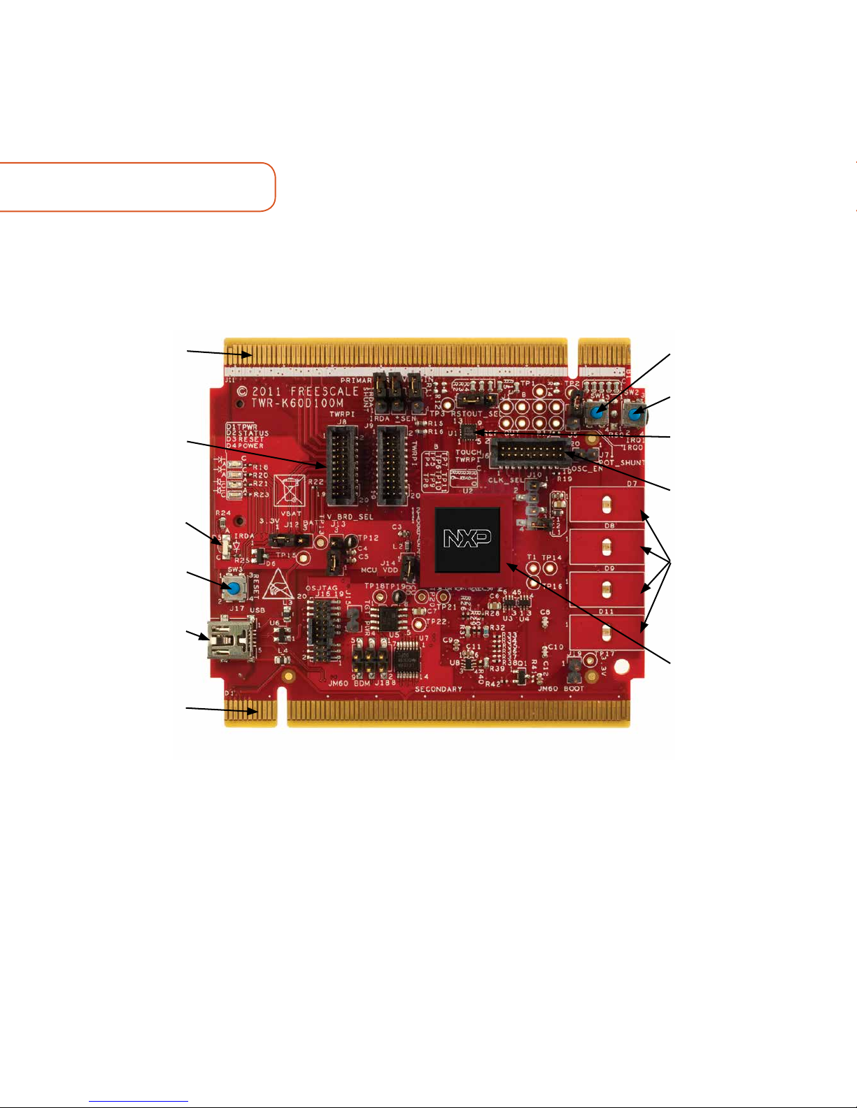
GET TO KNOW THE TWR-K60D100M BOARD
Primary
Connector
General Purpose
Tower Plug-In (TWRPI)
Socket
Infra-Red
SW3 (Reset)
Power/OSJTAG Mini-B
USB Connector
Secondary
Connector
SW1
SW2
MMA8451Q
Accelerometer
Touch TWRPI
Socket
LED/Touch
Buttons
D7, D8, D9,
and D11
MK60DN512VMD10
Kinetis MCU
Figure 1: Front side of TWR-K60D100M module
Page 3
3
www.nxp.com
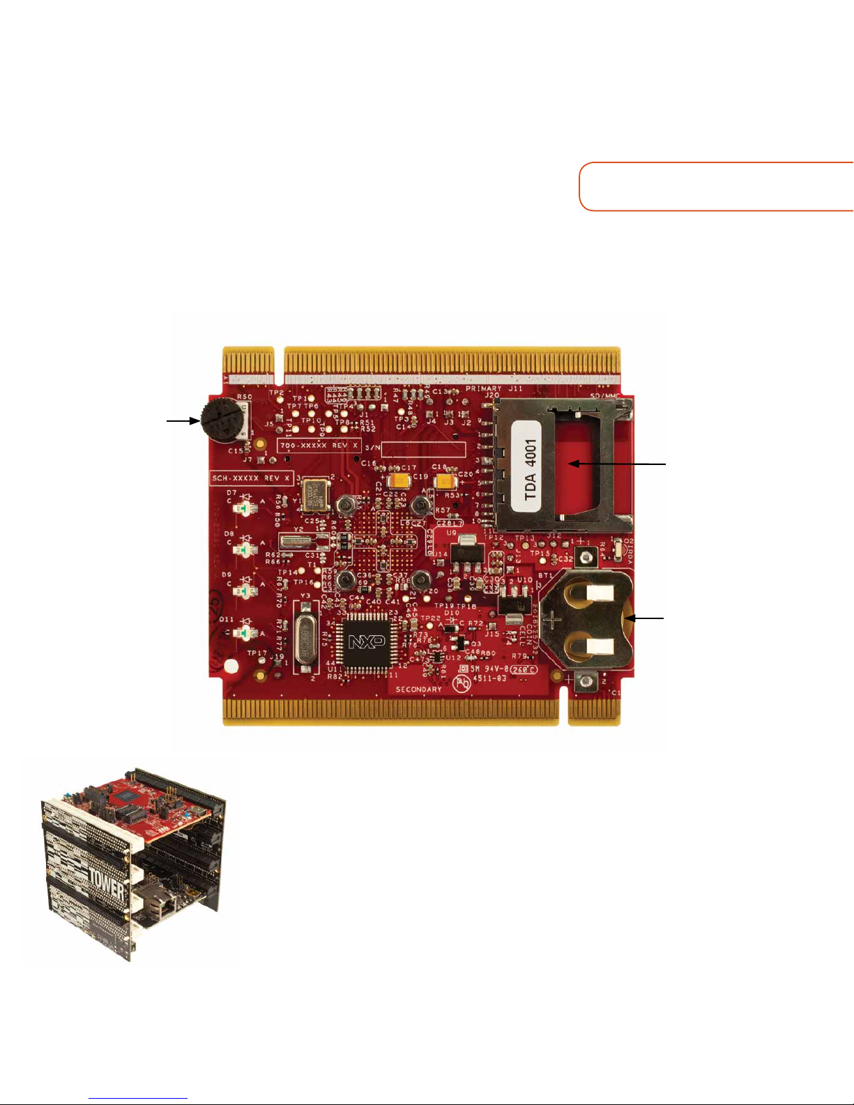
Figure 2: Back side of TWR-K60D100M module
Potentiometer
SD Card
Socket
VBAT (RTC)
Battery
Holder
TWR-K60D100M NXP TOWER SYSTEM BOARD
The TWR-K60D100M module is part of the NXP Tower System, a modular
development platform that enables rapid prototyping and tool re-use through
reconfigurable hardware. The TWR-K60D100M can be used with a broad
selection of Tower System peripheral modules.
Page 4

4
TWR-K60D100M FEATURES
• MK60DN512VMD10 MCU (100 MHz Arm® Cortex®-M4 core, 512 KB flash, Ethernet,
USB FS OTG, encryption, 144 MAPBGA)
• Integrated open source JTAG (OSJTAG) circuit
• MMA8451Q 3-axis accelerometer
• Four user-controlled status LEDs
• Four capacitive touch pads and two mechanical pushbuttons
• General-purpose TWRPI socket (Tower plug-in module)
• Potentiometer, SD card socket and coin-cell battery holder
Page 5

5
www.nxp.com
SOFTWARE INSTALLATION INSTRUCTIONS
In this Quick Start Guide, you will learn how to set up the TWR-K60D100M board and
run the included demonstrated software. For more detailed information, review the
user manual at www.nxp.com/TWR-K60D100M.
1
Configure the
Hardware
Connect one end of the USB cable to
the PC and the other end to the Power/
OSJTAG mini-B connector on the TWRK60D100M module. Allow the PC to
automatically configure the USB drivers if
needed.
2
Run the Quick
Start Demo
The LEDs on the board, D7 and D11, will
gradually illuminate as the board is tilted.
When rotated around the accelerometer’s
x-axis the Blue LED (D11) will illuminate.
Similarly, the red LED (D7) will gradually
illuminate as rotated around the y-axis.
3
Download
Software
Download installation software
and documentation at
www.nxp.com/TWR-K60D100M.
Page 6

6
TWR-K60D100M JUMPER OPTIONS
The following is a list of all jumper options. The default installed jumper settings are
shown in the shaded boxes.
EXPANDED SOFTWARE AND TOOLS NOW AVAILABLE FOR
KINETIS® MCUs
Additional details regarding the Quick
Start Demo are included as part of the
software development kit (SDK).
To take your design to the next level,
leverage the MCUXpresso SDK and
other online enablement software and
tools for Kinetis MCUs, available for
download at the relevant links listed
here.
• MCUXpresso SDK at
www.nxp.com/mcuxpresso
• MCUxpresso IDE at
www.nxp.com/mcuxpresso
• MCUXpresso Config Tools at
www.nxp.com/mcuxpresso
• Bootloader for Kinetis MCUs at
www.nxp.com/kboot
JUMPER OPTION SETTING DESCRIPTION
J13
V_BRD
Voltage
Selection
1-2 On-board power supply set to 3.3 V
2-3
On-board power supply set to 1.8 V (Some on-board
peripherals may not operate)
J14
MCU Power
Connection
ON Connect MCU to on-board power supply (V_BRD)
OFF
Isolate MCU from power (Connect to ammeter to measure
current)
J12
VBAT Power
Selection
1-2 Connect VBAT to on-board power supply
2-3
Connect VBAT to the higher voltage between on-board
power supply or coin-cell supply
Page 7

www.nxp.com
7
TWR-K60D100M JUMPER OPTIONS CONT.
JUMPER OPTION SETTING DESCRIPTION
J10
Clock Input
Source
Selection
1-2 Connect main EXTAL to on-board 50 MHz oscillator (Y1)
2-3
Connect EXTAL to the CLKIN0 signal on the elevator
connector
3-4
Connect ENET_CLKIN to the CLKIN0 signal on the elevator
connector
J19
OSJTAG
Bootloader
Selection
ON
OSJTAG bootloader mode (OSJTAG firmware
reprogramming)
OFF Debugger mode
J15
JTAG Board
Power
Connection
ON
Connect on-board 5 V supply to JTAG port (supports
powering board from JTAG pod supporting 5 V supply
ouput)
OFF Disconnect on-board 5 V supply from JTAG port
J2
IR Transmitter
Connection
ON Connect PTD7/CMT_IR0 to IR transmitter (D5)
OFF Disconnect PTD7/CMT_IR0 from IR transmitter (D5)
J3
IR Receiver
Connection
ON Connect PTC6/CMP0_IN0 to IR receiver (Q2)
OFF Disconnect PTC6/CMP0_IN0 from IR receiver (Q2)
J4
IR Receiver
Connection
ON Connect USB0_VBUS from elevator to VREGIN
OFF Disconnect USB0_VBUS from elevator to VREGIN
J1 GPIO to Drive
RSTOUT
1-2 PTE27 to drive RSTOUT
2-3 PTB8 to drive RSTOUT
J5 Potentiometer
Shunt
ON Connect potentiometer to ADC
OFF Disconnect potentiometer (For lower power measurement)
J7 Oscillator
Enable
ON Disables 50 MHz oscillator (Y1)
OFF Enables 50 MHz oscillator (Y1)
Page 8

SUPPORT
Visit www.nxp.com/support for a list of
phone numbers within your region.
WARRANTY
Visit www.nxp.com/warranty for
complete warranty information.
www.nxp.com/TWR-K60D100M,
and www.nxp.com/Tower
NXP, the NXP logo, Kinetis, and Tower are trademarks of NXP B.V. All other product or
service names are the property of their respective owners. Arm and Cortex are registered
trademarks of Arm Limited (or its subsidiaries) in the EU and/or elsewhere. All rights
reserved. © 2012–2017 NXP B.V.
Doc Number: TWRK60D100MQSG REV 3
Agile Number: 926-78671 REV E
Get Started
Download installation
software and documentation at
www.nxp.com/TWR-K60D100M.
 Loading...