

Page 1

TRK-MPC5606B
StarterTRAK Development Board
Quick Start Guide
S tarterTRAK
Page 2
Quick Start Guide
2
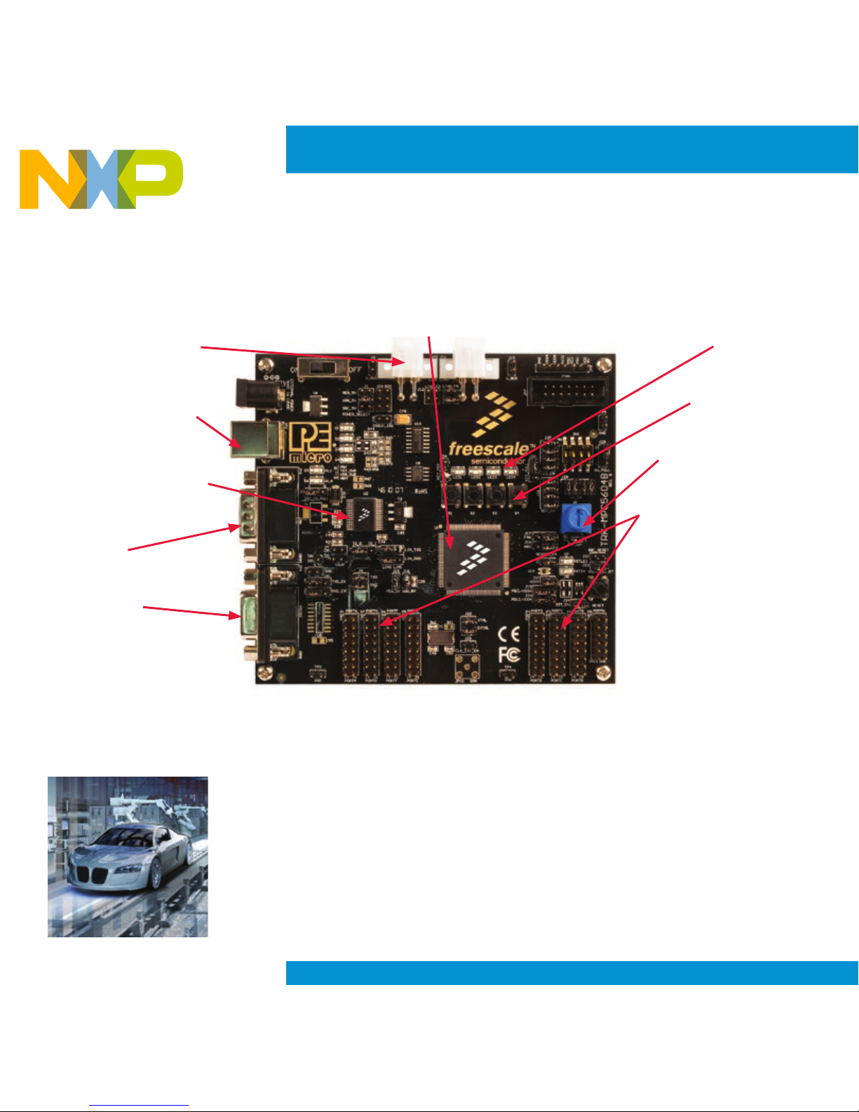
LIN Connectors
USB Connector/
Power Supply
MCZ3390S5EK
System Basis Chip
CAN
RS232
MPC5606B
LEDs
Switches
Potentiometer
All Available Pins
Figure 1: TRK-MPC5606B Board*
TRK-MPC5606B
Freescale StarterTRAK
The TRK-MPC5606B board is part of the Freescale StarterTRAK series, a development
platform that enables rapid prototyping and tool re-use. Take your
design to the next
level and begin constructing with your StarterTRAK system today.
Get to Know the TRK-MPC5606B
*Graphic subject to change
Page 3

TRK-MPC5606B
3
Install Software
and Tools
• Run setup.exe from the installation
media. This will install the following
software tools:
CodeWarrior Development Studio v10.5
(Special Edition), RAppID Init tool, RAppID
Boot loader utility, FreeMASTER utility,
CodeWarrior Project Maker utility, Driver
code for the MPC5606B and Example
projects to help you to get started with the
Fast Start Kit.
• MPC560xB/C/D series MCU
(144-pin LQFP)
• On-board JTAG connection via open
source OSBDM circuit using the
MPC9S08JM MCU
See pemicro.com/osbdm for
source code
• MCZ3390S5EK system basis chip
with advanced power management
and integrated CAN tranciever and
LIN 2.0 interface
• CAN interface
• LIN interface
• Analog interface with potentiometer
• High-efficiency LEDs
• Serial communication interface
Step-by-Step Installation Instructions
TRK-MPC5606B Features
In this Quick Start Guide, you will learn how to install the software tools
provided in the Fast Start Kit for TRK-MPC5606B installation media,
how to set up TRK-MPC5606B board and run a LED example that
demonstrates all the software tools provided with the installation media.
1
Page 4

Quick Start Guide
4
Learn More About the
MPC5606B
Read the release notes and
documentation located on the DVD and at
freescale.com/StarterTRAK.
• The Qorivva Simple Cookbook provides
simple code examples for manipulating
different peripherals on the MPC5606B.
• RAppID Init tool is a graphical
development which will enable you to
quickly and easily configure the MCU
and generate complete initialization
code. It is also a learning tool for
gaining understanding of the MCU and
its peripherals and will help you to get
to market faster.
• CodeWarrior 10.5 with examples from
the Simple Cookbook
Connect the
USB Cable
Connect one end of the USB cable to
the PC and the other end to the mini-B
connector on the TRK-MPC5606B board.
Allow the PC to automatically configure the
USB drivers if needed.
Open Supporting
Documentation
Open the TRK_MPC5606B training
document and TRK-MPC5606B user
manuals from the Documentation folder
included in the installation media.
Explore Further with the
LED Example Project
To run a demonstration using the TRKMPC5606B, follow the instructions for
the LED example included in the training
document located in the document folder of
installation media.
2
3
4
5
Page 5

TRK-MPC5606B
5
Jumper Option Setting Description
J1
System Power
1-2 External Power 9 V DC to 12 V DC Regulated Down to 5 V DC
3-4 USB OSBDM Supplies 5 V DC
5-6 SBC33905 Supplies 5 V DC
J2
SBC I/O LED Pull
Up/Down
1-2 Pull Up
2-3 Pull Down
J3 SBC I/O Signal
1-2 I/O-0
2-3 I/O-1
J4
SBC DBG Short
to GND
1-2 Short SBC DBG Pin to GND, Bypass R21 and D11
J5 SBC DBG Pull Up 1-2
Pull Up SBC DBG Pin to SBC Power Supply via 330 Ohm
Resistor
J6-A CAN TX Signal
1-2 Connects CAN TXD signals to SBC CAN Transceiver
2-3
Connects CAN TXD signals to TJA1050T CAN Transceiver (not
populated)
J6-B CAN RX Signal
1-2 Connects CAN RXD signals to SBC CAN transceiver
Connects CAN RXD signals to TJA1050T CAN Transceiver (not
populated)
J7 RS232 TXD Signal
1-2 MCU TXD to Virtual Serial Port
2-3 MCU TXD to RS232 Transceiver
J8 RS232 RXD Signal
1-2 MCU RXD to Virtual Serial Port
2-3 MCU RXD to RS232 Transceiver
J9 LIN1 VBus Enable 1-2 Provides Power to LIN1 Connector
J10 LIN0 VBus Enable 1-2 Provides Power to LIN0 Connector
J11
LIN0 Signals to
Connector Enable
1-2, 3-4 Connects LIN0 Signals to LIN0 Connector
TRK-MPC5606B Jumper Options
Page 6

Quick Start Guide
6
Jumper Option Setting Description
J12
LIN1 Signals to
Connector Enable
1-2, 3-4 Connects LIN1 Signals to LIN1 Connector
J13 LIN TXD Signal
1-2 MCU LIN0TX to Transceiver
2-3 MCU LIN1TX to Transceiver
J14 LIN RXD Signal
1-2 MCU LIN0RX to Transceiver
2-3 MCU LIN1RX to Transceiver
J15 MCU VDD Enable 1-2 Provides Power to MCU, Current Measurement
J16 VDD_BV Enable 1-2 Provides Power to VDD_BV
J17 FAB
1-2 FAB Pulled Up High
2-3 FAB Pulled Down Low
J18 ABS
1-2 ABS Pulled Up High
2-3 ABS Pulled Down Low
J19
MPC5604B/
MPC5606B for
Pin 81
1-2 MPC5604B PB11
2-3 MPC5606B VSSA
J20
MPC5604B/
MPC5606B for
Pin 82
1-2 MPC5604B PD12
2-3 MPC5606B VDDA
J21 VDDA Enable 1-2 Provides Power to VDDA, Current Measurement
J22
External Crystal
Circuitry Enable
1-2 XTAL
3-4 EXTAL
J23
External Oscillator
via SMA Enable
1-2 EXTAL
J24
Pushbutton Active
High or Low,
Opposite of J25
1-2 Active Low
2-3 Active High
TRK-MPC5606B Jumper Options
(continued)
Page 7

TRK-MPC5606B
7
Jumper Option Setting Description
J25
Pushbutton Pull
Up/Down Enable,
Opposite of J24
1-2 Pull Up
2-3 Pull Down
J26
Pushbutton signals
Enable
1-2, 3-4,
5-6, 7-8
Connects MCU port PE0, PE1, PE2 and PE3 to Corresponding
push buttons
J27 LED Signals Enable
1-2, 3-4,
5-6, 7-8
Connects MCU port PE4, PE5, PE6 and PE7 to Corresponding
LEDs
J28
DIL Switch Signals
Enable
1-2, 3-4,
5-6, 7-8
Connects MCU Port PG6, PG7, PG8 and PG9 to
Corresponding DIL Switch
J29
DIL Switch Active
High or Low
1-2 Active High
2-3 Active Low
J30
Analog Input
Enable
1-2 Connects MCU ANP0 to Potentiometer
J31
Photo Sensor
Enable
1-2 Connects MCU ANP1 to Photo Cell
J32
SBC Reset to MCU
Enable
1-2 Enables SBC Reset Signal to Trigger MCU Reset
J33
OSBDM Reset to
MCU Enable
1-2 Enables OSBDM Reset Signal to Trigger MCU Reset
J34
System Reset
Enable
1-2 Connects Reset Sources to MCU Reset Signal
J35
OSBDM IRQ
Enable
1-2 Enables OSBDM to Generate an Interrupt
J38 SPI Enable
1-2 Connects MCU PH3 to CS signal of SBC
3-4 Connects MCU PH2 to SCLK signal of SBC
5-6 Connects MCU PH1 to MOSI signal of SBC
7-8 Connects MCU PH0 to MISO signal of SBC
TRK-MPC5606B Jumper Options
(continued)
Page 8

Quick Start Guide
For more information, visit
freescale.com/StarterTRAK
Freescale, the Freescale logo and CodeWarrior are trademarks of Freescale
Semiconductor, Inc., Reg. U.S. Pat. & Tm. Off. Qorivva is a trademark of
Freescale Semiconductor, Inc. All other product or service names are the
property of their respective owners. ©2012–2014FreescaleSemiconductor,Inc.
Doc Number: MPC5606BQSG REV 4
Agile Number: 926-78721 REV C
Support
Visit freescale.com/support for a list of phone
numbers within your region.
Warranty
Visit freescale.com/warranty for complete
warranty information.
 Loading...