

Page 1

UM10276_1
TED-Kit 2
Rev. 1.29 — 20 August 2010
User manual
Document information
Info
Content
Keywords
TED-Kit 2, HITAG, Immobilizer, PKE, RKE
Abstract
The purpose of this document is to describe how to install and use the
TED-Kit 2 and its GUI software. The intended audiences are engineers
planning to use the TED-Kit 2.
Page 2

NXP Semiconductors
UM10276_1
TED-Kit 2 User Manual
All information provided in this document is subject to legal disclaimers.
© NXP B.V. 2010. All rights reserved.
User manual
Rev. 1.29 — 20 August 2010
2 of 79
Contact information
For additional information, please visit: http://www.nxp.com
For sales office addresses, please send an email to: salesaddresses@nxp.com
Page 3

NXP Semiconductors
UM10276_1
TED-Kit 2 User Manual
All information provided in this document is subject to legal disclaimers.
© NXP B.V. 2010. All rights reserved.
User manual
Rev. 1.29 — 20 August 2010
3 of 79
1. Introduction
The purpose of this document is to describe how to install and use the TED-Kit 2 and its
GUI software. The intended audiences are engineers planning to use the TED-Kit 2.
Section 2 gives a very brief system overview to explain all the terms used throughout this
manual.
Section 3 describes in detail what requirements the host system must meet to use the
TED-Kit 2 software and hardware, how to install the software and how to remove it afterwards.
Section 4 gives a quick-start in 5 simple steps to authenticate with a HITAG 2 transponder and show the content of its EEPROM.
Section 5 introduces the GUI and shows how to accomplish common tasks like configuring the base station and interacting with a transponder IC.
Section 6 describes all elements of the user interface in detail; it may be used as a reference.
Section 7 describes some tips & tricks and how to deal with operation errors.
Section 8 shows the PCBs and schematics of the TED-Kit 2 hardware.
2. System overview
This chapter will give a brief system overview to explain all the terms used throughout
this manual.
The TED-Kit 2 system consists of hardware and software used to evaluate and demonstrate the base station and transponder functionality of NXP devices. Fig 1 illustrates all
major components of a typical system setup.
Page 4
NXP Semiconductors
UM10276_1
TED-Kit 2 User Manual
All information provided in this document is subject to legal disclaimers.
© NXP B.V. 2010. All rights reserved.
User manual
Rev. 1.29 — 20 August 2010
4 of 79
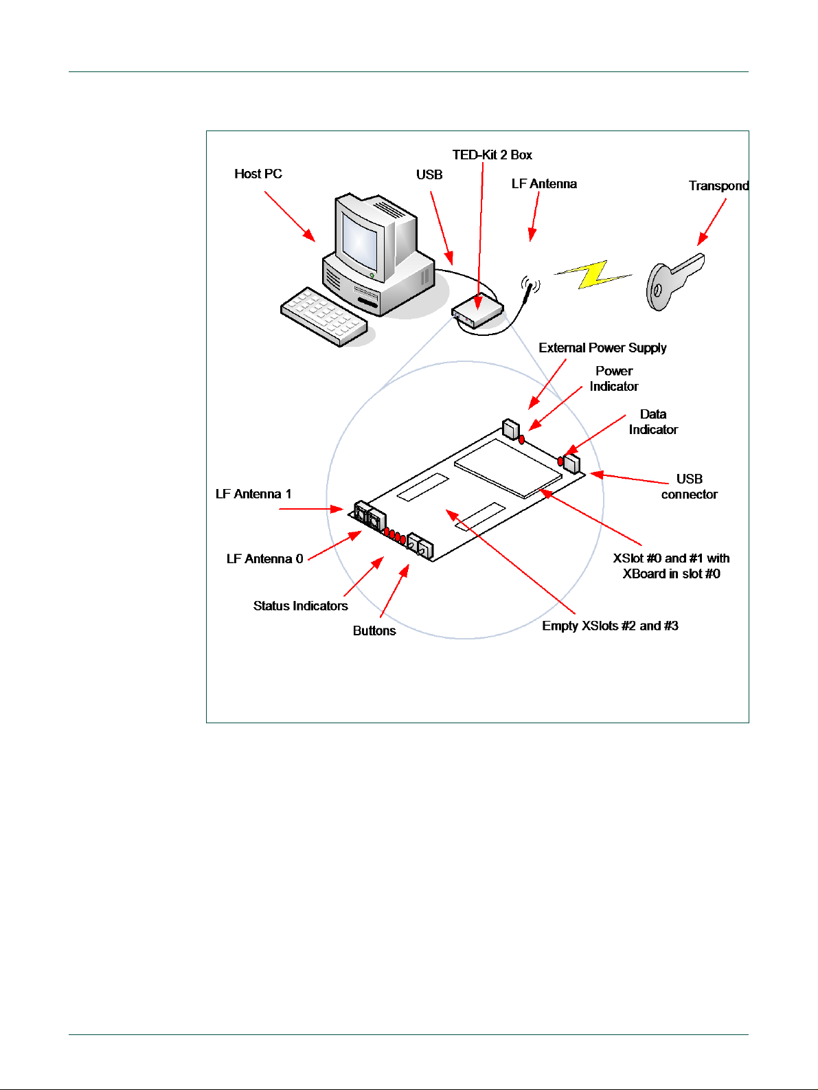
Fig 1. System Overview
The host PC running the TED-Kit 2 software connects with the TED-Kit 2 box via USB.
One or two external LF antennas are connected (depending on the internal configuration). Via the antenna, the TED-Kit 2 box exchanges data with the transponder IC found
in e.g. a key.
The TED-Kit 2 box itself has 4 so called XSlots. Each of them can take one XBoard containing actual functionality like e.g. an ABIC1 base station IC. On one side of the box, the
USB connector and the external power supply can be found. The later is used if the
XBoards require extra power which cannot be delivered by the USB port. Besides that, a
power and a data indicator can be found. The first lights as soon as power is available
and the TED-Kit 2 box can be used, the second lights if data are transmitted to or from it
via USB.
On the opposite side of the TED-Kit 2 box, the two antenna plugs for LF antenna #0 and
#1 can be found. Aside of them, 4 LED indicators are located used for several different
purposes (e.g. to indicate some status or error condition). Next to the LEDs, 2 buttons
Page 5

NXP Semiconductors
UM10276_1
TED-Kit 2 User Manual
All information provided in this document is subject to legal disclaimers.
© NXP B.V. 2010. All rights reserved.
User manual
Rev. 1.29 — 20 August 2010
5 of 79
Application
Hardware
Transponder
XBoards
ID
Example
LF
UHF
Immobilizer
HITAG2
A
PCF7936A
ABIC1
n/a
HITAG2+
A
PCF7946A
HITAG2+EE
A
PCF7947A
HITAG2-Extended
E
PCF7937EA
HITAG3
X
PCF7961X
HITAG-Pro
P
PCF7939P
HITAG-Pro 2
V
NCF2950V
Remote Keyless Entry
RKE
PCF7945A
LoPSTer
Passive Keyless Entry
PKE
PCF7952A
are found which can be used by the firmware of the TED-Kit 2 box (they have no function
yet).
2.1 Supported applications and hardware
The table below shows the supported applications and the hardware required by the
TED-Kit 2 system:
Table 1. Supported applications and hardware
3. Setup
This chapter will explain the necessary system requirements for the TED-Kit 2 software
and hardware as well as how to install and remove the software.
3.1 System requirements
The computer system used as host for the TED-Kit 2 software and hardware must meet
the following requirements:
1. It must run Windows XP. Although it is expected that Windows 2000, Vista and 7 will
work also, these systems are not tested and not supported.
2. For each TED-Kit 2 box, a free USB (Version 2) port must be available on the host
PC. Although it is expected that USB V1 or V1.1 ports will work also, this is not
tested and thus, not supported.
3. The screen size shall be at least 1024 x 768 pixels. Although the software will run on
screens with lower size, it is not recommended because the use of GUI and its forms
will become less convenient.
4. Software to show Adobe PDF documents shall be installed on the system to be able
to read the documentation and the data sheets.
5. The user account used to install the software must have administration rights (due to
device driver and system component installation procedures).
3.2 Installing the software
Note: To avoid any conflicts with previous versions of this software, it is recommended to remove them before continue installing a new version.
Page 6

NXP Semiconductors
UM10276_1
TED-Kit 2 User Manual
All information provided in this document is subject to legal disclaimers.
© NXP B.V. 2010. All rights reserved.
User manual
Rev. 1.29 — 20 August 2010
6 of 79
The installation process is quite simple. Insert the media containing the TED-Kit 2 Setup
software in the host PC and run Setup.exe. The installer will guide the user through the
installation process.
Before starting the software for the first time, please install the hardware (see section 3.3,
page 6).
Note: To read the documentation and the data sheets, proper PDF reader software
is required. Please make sure your system contains such software, e.g. Adobe’s
PDF Reader (available for free from Adobe).
3.3 Installing the hardware
Usually, the hardware comes ready to use with everything installed already. In case the
XBoard is delivered separately, it must be installed in the TED-Kit 2 board first:
1. Open the TED-Kit 2 box removing 4 screws (2 at each front side).
2. Plug the ABIC1 XBoard in the XSlot #0 of the TED-Kit 2 main board. XSlot #0 can be
found on the main board; a label says Extension slots 0 and 1. It is the one closer to
the USB and power supply plugs. It might be necessary to open the TED-Kit 2 box
first.
3. Plug the antenna in port LF0. Port LF0 is the antenna port closer to the 4 status
LEDs.
4. Plug the USB cable in the USB port of the TED-Kit 2 and the host PC.
5. The Windows Hardware Wizard will pop-up and ask for the appropriate driver. Point
it to:
[TED-Kit 2 Installation Folder]\Device Driver
6. The Hardware Wizard will finish the driver installation.
3.4 Removing the software
4. Quick start
To remove the software from the PC, the standard procedure of the Windows operating
system shall be used. It will delete all software components as well as the installed driver
software, manuals and (if installed) the software development components.
This section shows how to connect with a transponder, authenticate and read out its
EEPROM content very briefly. It will not give any detailed explanations. To walk through
the steps, the software must be already successfully installed. The PCF7936AS (HITAG 2) transponder used in this example must be configured to do authentication in plain
mode with the default settings and passwords.
1. Start the GUI via (Fig 2):
SSttaarrttAAllll PPrrooggrraammssNNXXPP SSeemmiiccoonndduuccttoorrssTTEEDD--KKiitt 22 VV33TTEEDD--KKiitt 2
2
Page 7
NXP Semiconductors
UM10276_1
TED-Kit 2 User Manual
All information provided in this document is subject to legal disclaimers.
© NXP B.V. 2010. All rights reserved.
User manual
Rev. 1.29 — 20 August 2010
7 of 79
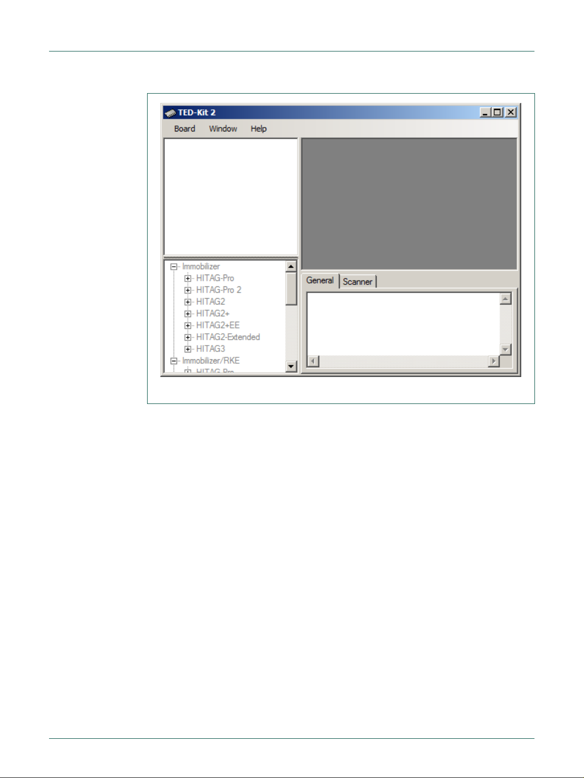
Fig 2. TED-Kit 2 main window
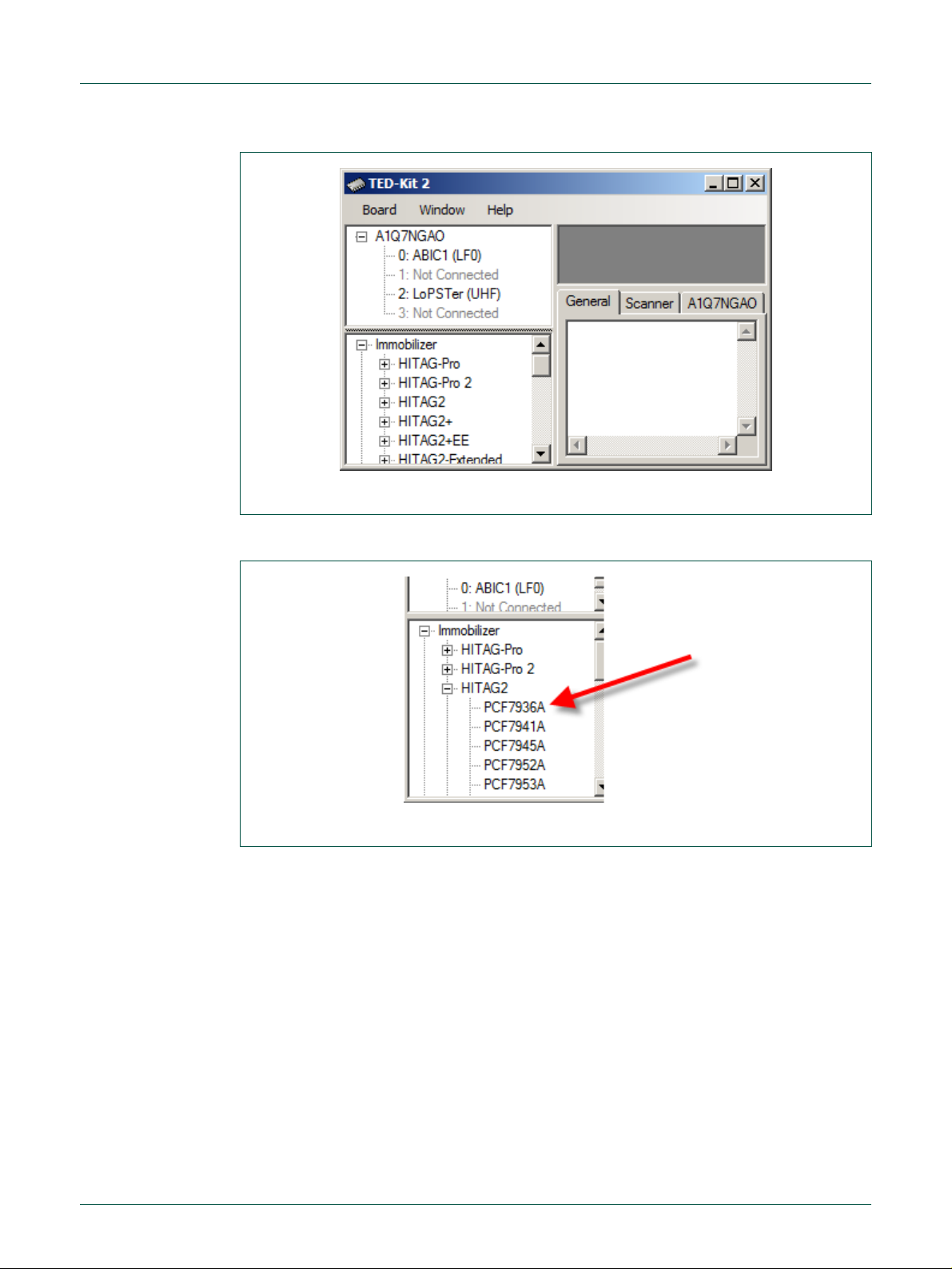
Fig 3. HITAG 2 immobilizer selection
2. Expand the HHIITTAAGG 22 node of the IImmmmoobbiilliizzeerr tree in the applet view and double-click
PPCCFF77993366A
A to open the Immobilizer applet form (Fig 3).
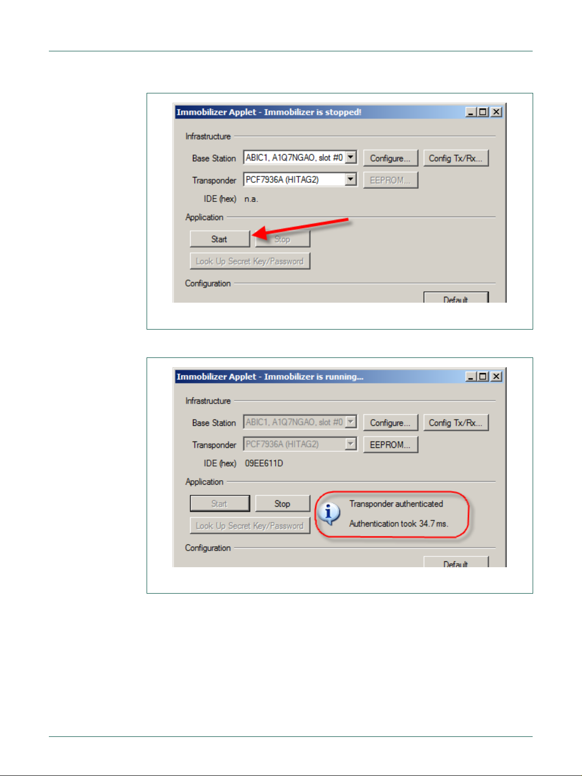
3. Click the SSttaarrtt button to start the immobilizer applet form popping up (Fig 4).
Page 8
NXP Semiconductors
UM10276_1
TED-Kit 2 User Manual
All information provided in this document is subject to legal disclaimers.
© NXP B.V. 2010. All rights reserved.
User manual
Rev. 1.29 — 20 August 2010
8 of 79
Fig 4. HITAG2 authentication starting
Fig 5. HITAG 2 authentication running
4. The immobilizer applet runs and authenticates the transponder with the default
communication and authentication settings (Fig 5).
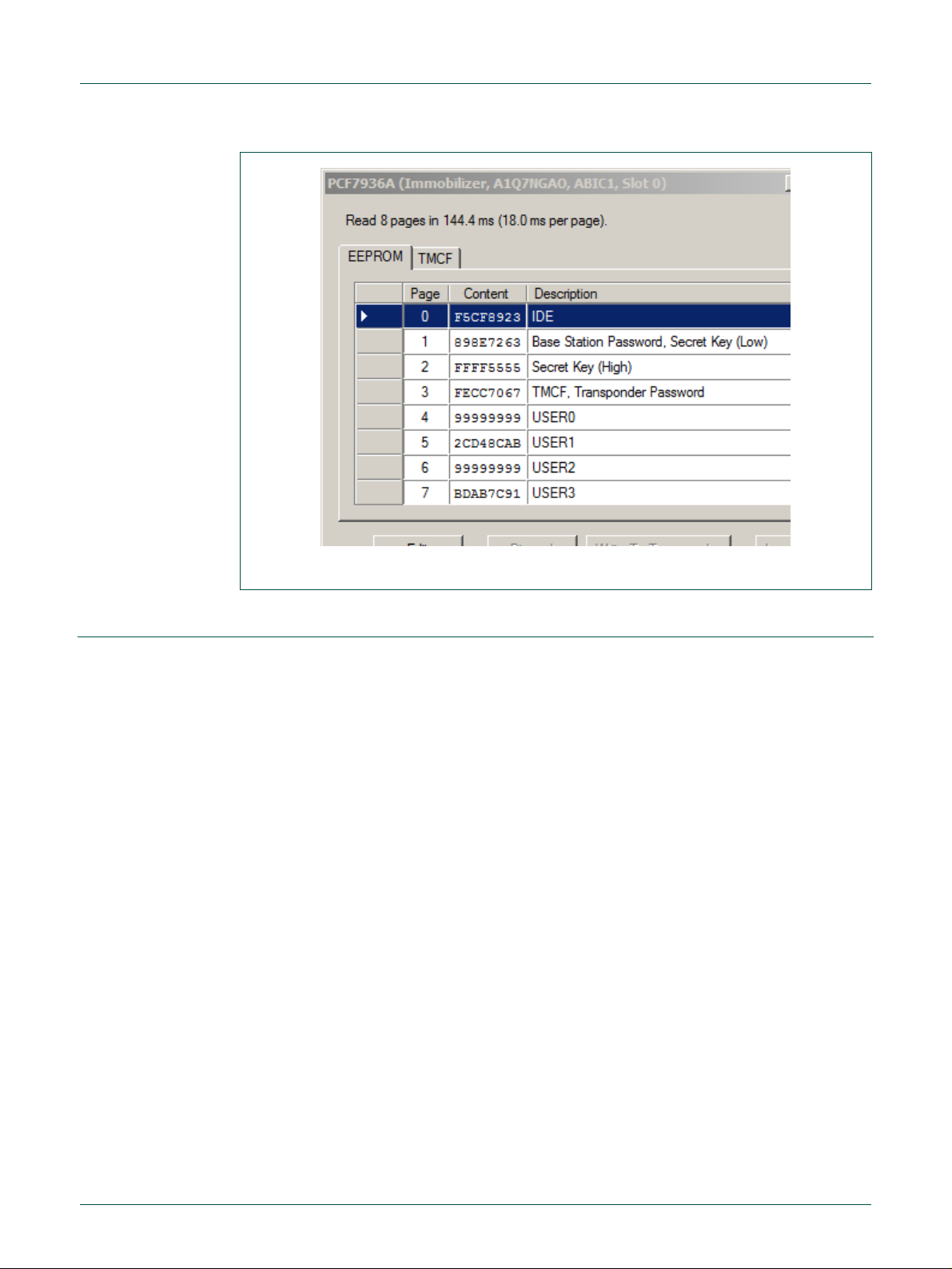
5. Click the EEEEPPRROOMM…… button to open the memory window and see the content (Fig 6).
Page 9
NXP Semiconductors
UM10276_1
TED-Kit 2 User Manual
All information provided in this document is subject to legal disclaimers.
© NXP B.V. 2010. All rights reserved.
User manual
Rev. 1.29 — 20 August 2010
9 of 79
Fig 6. HITAG2 EEPROM content
5. Using the GUI software
This chapter will explain the basic concepts of the GUI software and how to perform
common tasks. For a detailed reference of all functions offered, p 7,
page 39.
To explain the functionality, the Immobilizer application with a PCF7991 (ABIC1) base
station and a PCF7937EA (HITAG2-Extended) transponder is demonstrated.
5.1 Start the GUI
It is assumed that no TED-Kit 2 is currently plugged-in. To start the GUI, click:
SSttaarrttAAllll PPrrooggrraammssNNXXPP SSeemmiiccoonndduuccttoorrssTTEEDD--KKiitt 22 VV33TTEEDD--KKiitt 22
The splash screen appears, the application loads and shows the main window (Fig 7).
Page 10
NXP Semiconductors
UM10276_1
TED-Kit 2 User Manual
All information provided in this document is subject to legal disclaimers.
© NXP B.V. 2010. All rights reserved.
User manual
Rev. 1.29 — 20 August 2010
10 of 79
Fig 7. TED-Kit 2 main window
The GUI will store its window size and location as well as the size of the Hardware-, Applet- and Message View. Each time it is restarted, these settings are restored. The settings are saved in this file:
[Current User’s Application Data]\NXP Semiconductors\TED-Kit 2\[Version]\config.dat
For a typical Windows XP installation, this resolves to (for user Me and software version
3.1.0):
C:\Documents and Settings\Me\Application Data\NXP Semiconductors\TED-Kit 2\3.1.0\config.dat
5.2 Exploring the connected TED-Kit 2 boxes
The upper left part of the main window always shows the hardware view. Here, a list with
all connected TED-Kit 2 boxes appears. For each TED-Kit 2 box found, a new root node
is created in the tree. Now, plug-in the TED-Kit 2 box in any USB port of the PC and wait
until the hardware is detected and the hardware refreshes its content.
Note: The TED-Kit 2 GUI is able of handling multiple TED-Kit 2 boxes at once.
DON’T start a new GUI for each TED-Kit 2 box attached to the computer. This will
result in undefined behavior.
Depending on the board, the firmware or the hardware check may fail. This will result in
different warning dialogs explained in sections 5.8 and 5.9.
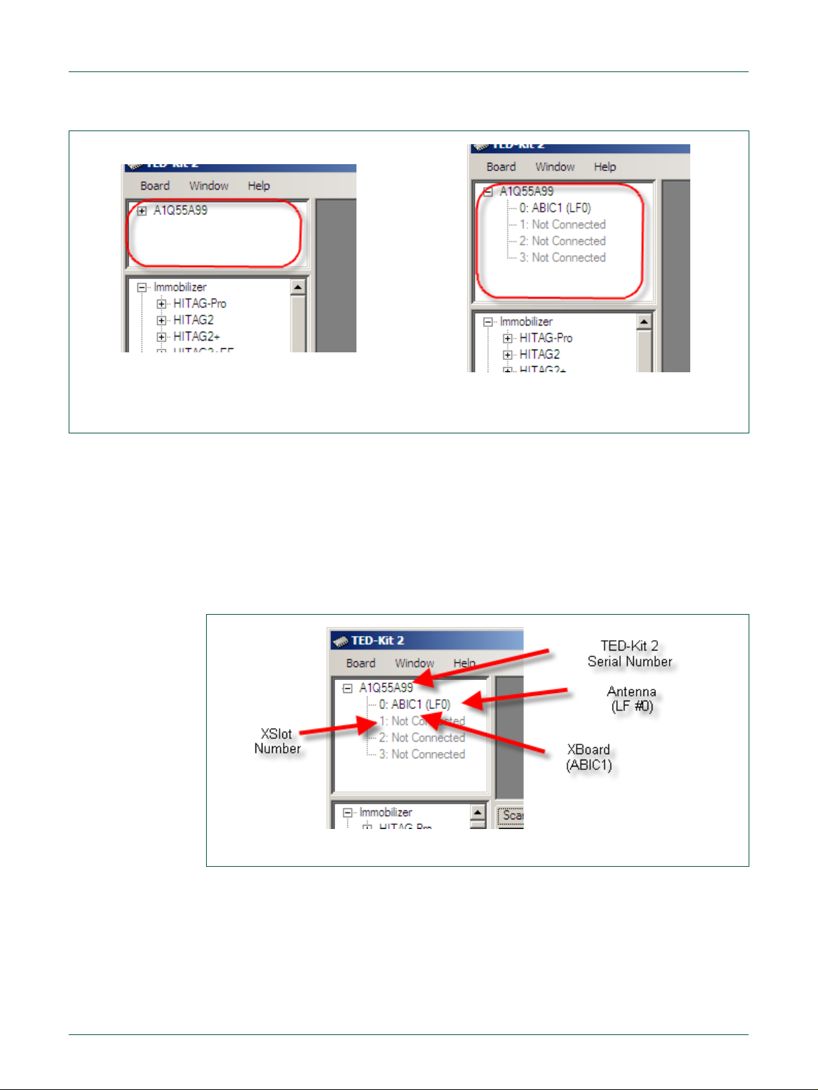
If everything is OK with the board, the hardware view looks like Fig 8a. It shows one connected TED-Kit 2 box in the hardware view with the serial number A1Q55A99.
Page 11
NXP Semiconductors
UM10276_1
TED-Kit 2 User Manual
All information provided in this document is subject to legal disclaimers.
© NXP B.V. 2010. All rights reserved.
User manual
Rev. 1.29 — 20 August 2010
11 of 79
a. collapsed
b. expanded
Fig 8. Hardware view
Fig 9. Hardware view details
Note: TED-Kit 2 boxes can be plugged-in before or after starting the GUI. They are
automatically detected. The hardware can also be removed at any time while the
GUI is running.
Expanding the nodes will show the configuration of each TED-Kit 2 box according to the
XSlots and XBoards plugged in. For each XBoard found, the connected antenna(s) are
shown in the tree also (Fig 8b).
The TED-Kit 2 box currently connected has one XBoard: In slot #0, an ABIC1 which is
connected to LF antenna #0 (LF0). The slots #1, #2 and #3 are empty. The Hardware
View information is shown in Fig 9.
To get an even more detailed look at each TED-Kit 2 box, double-click on the tree node
of the TED-Kit 2 of interest. A window showing all details available opens (refer to section
6.5 for details).
Double-clicking an ABIC1 node shown in the hardware view will open the ABIC1 XBoard
configuration window explained in section 6.6.1.
Double-clicking a LoPSTer node will open the LoPSTer XBoard configuration window
explained in section 6.6.2.
Page 12
NXP Semiconductors
UM10276_1
TED-Kit 2 User Manual
All information provided in this document is subject to legal disclaimers.
© NXP B.V. 2010. All rights reserved.
User manual
Rev. 1.29 — 20 August 2010
12 of 79
a. Transponder families
c. Transponder types
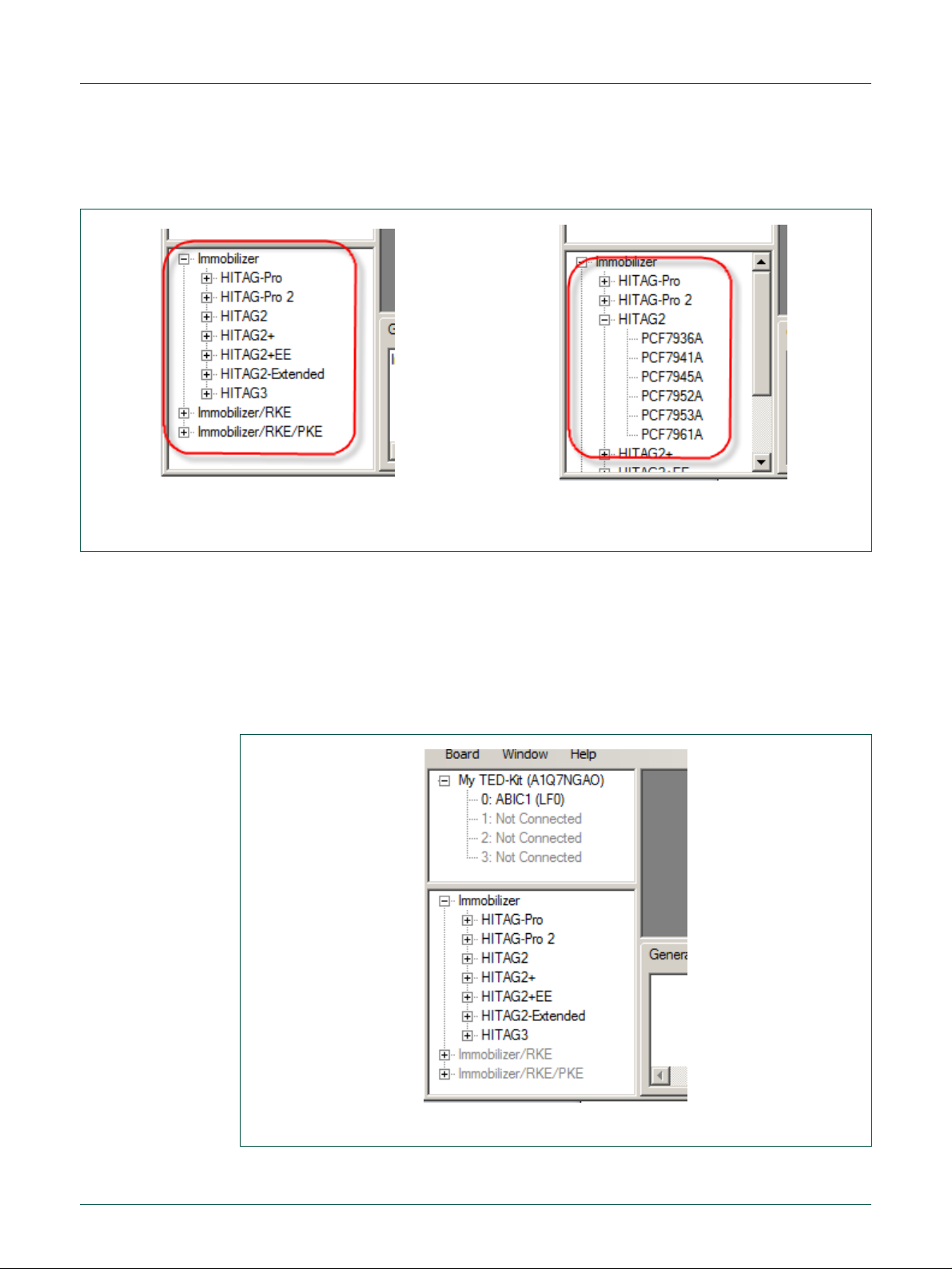
Fig 10. Applet view
Fig 11. Applet view deactivated
5.3 Exploring the available applets
The lower left part of the main window shows the applet view (Fig 10a).
Here, all available applets are listed. In the current version of the software, three different
applets exist: Immobilizer, Immobilizer/RKE and Immobilizer/RKE/PKE. Expanding the
Immobilizer node shows all transponder families supported by this applet, expanding a
family node shows all transponder types belonging to that family (Fig 10b).
The Applet View not just shows the available applets and supported transponder families. It also tracks the connected TED-Kit 2 boxes and their resources. If all resources are
consumed by one or more applets running, the applets which cannot be started anymore
are grayed out.
Page 13

NXP Semiconductors
UM10276_1
TED-Kit 2 User Manual
All information provided in this document is subject to legal disclaimers.
© NXP B.V. 2010. All rights reserved.
User manual
Rev. 1.29 — 20 August 2010
13 of 79
Fig 12. Immobilizer applet
In Fig 11 there is one TED-Kit 2 box connected with one ABIC1 base station XBoard.
Thus, the Immobilizer applet could be started.
To run an RKE or PKE applet, a LoPSTer XBoard is required. Because the current TEDKit 2 does not have any, the Immobilizer/RKE and the Immobilizer/RKE/PKE applet trees
are grayed out.
To run any of them, the current TED-Kit 2 box must be equipped with a proper LoPSTer
board or a second TED-Kit 2 box (with at least one ABIC1 XBoard and one LoPSTer
board) must be plugged-in. This can be done without closing the TED-Kit 2 GUI.
Note: If an applet (e.g. Immobilizer) consumes all remaining resources, the affected parts of the applet view are also grayed out to avoid starting applets without
having proper hardware resources.
5.4 Running immobilizer applet
To run the Immobilizer applet, double click at one of the transponders of the desired
family node below the Immobilizer node of the applet view. This will set the default values
for this transponder in advance (all settings can be changed afterwards though).
The Immobilizer applet window appears (Fig 12).
The window contains three different parts: In the upper part, the IInnffrraassttrruuccttuurree frame
which shows the currently configured infrastructure for the applet. In the window shown
Page 14

NXP Semiconductors
UM10276_1
TED-Kit 2 User Manual
All information provided in this document is subject to legal disclaimers.
© NXP B.V. 2010. All rights reserved.
User manual
Rev. 1.29 — 20 August 2010
14 of 79
Fig 13. ABIC1 configuration window
above, the infrastructure consists of one base station (the ABIC1 in slot #0 of the TEDKit 2 box named My TED-Kit) and one PCF7937E transponder of the HITAG 2 Extended
family.
In the middle part, the AApppplliiccaattiioonn frame which allows starting and stopping the application. Currently, it is stopped (the start button is active and window title says: …stopped).
The CCoonnffiigguurraattiioonn frame at the bottom of the window allows making all settings relevant
for the applet. That includes authentication modes, passwords etc.
5.4.1 Configuring the ABIC1
To configure an ABIC1 XBoard, two options are available. Either double click at the
proper node of the Hardware View (see section 6.2) or click the CCoonnffiigguurree…… button in the
applet window. The following window appears (Fig 13).
For a detailed description of the settings, please refer to section 6.6.
Page 15
NXP Semiconductors
UM10276_1
TED-Kit 2 User Manual
All information provided in this document is subject to legal disclaimers.
© NXP B.V. 2010. All rights reserved.
User manual
Rev. 1.29 — 20 August 2010
15 of 79
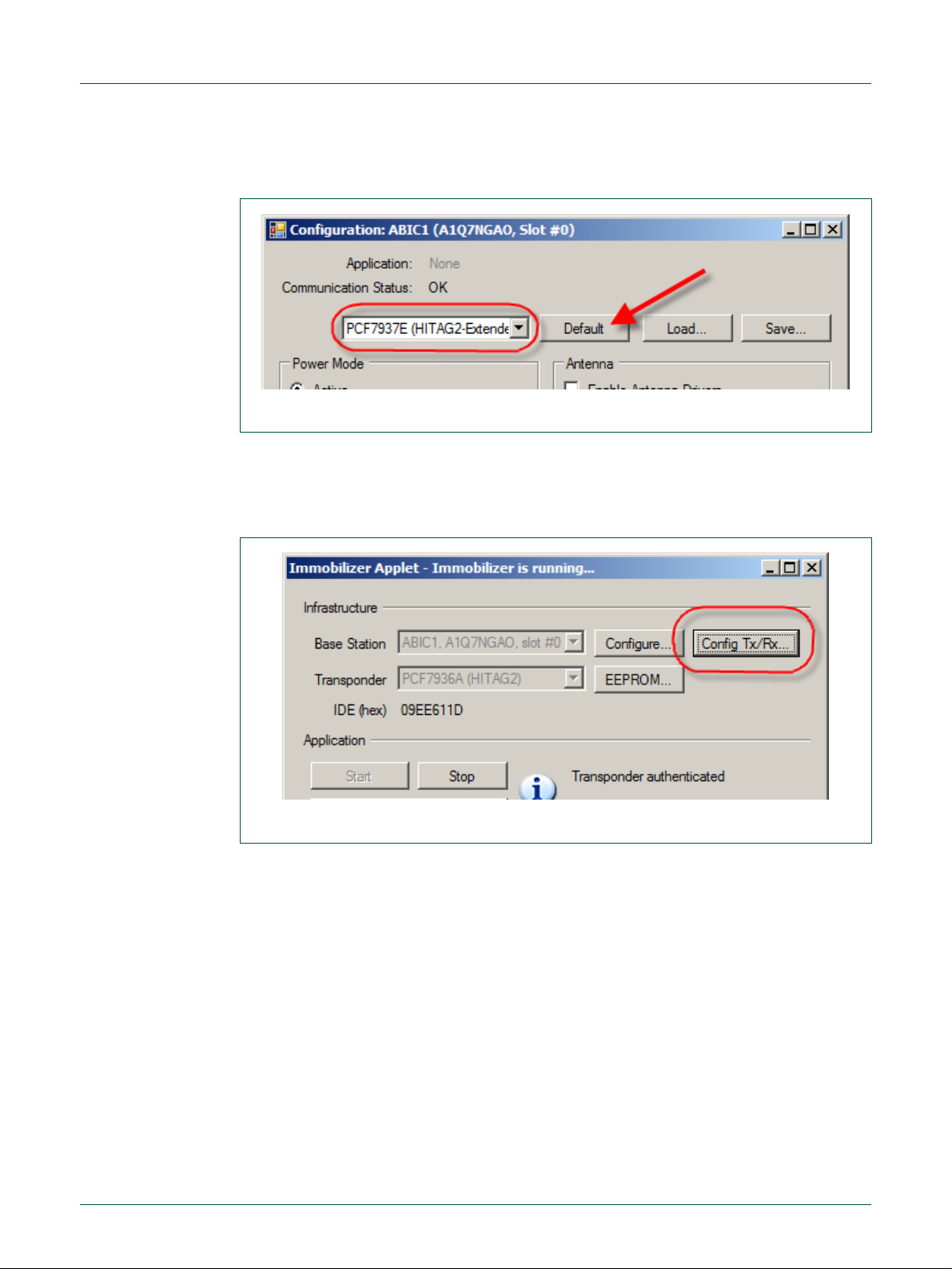
Fig 14. ABIC1 default configuration
Fig 15. Immobilizer Tx/Rx configuration
In this example, the ABIC1 default settings are used. To re-apply them, select the transponder family being used (HITAG2-Extended for this example) and click DDeeffaauulltt (Fig 14).
5.4.2 Communication settings
The Immobilizer applet allows configuring the transmission and reception parameters for
the LF-Link in detail. To view or change the transmission and reception, click the CCoonnffiigg
… button in the Immobilizer applet window ().
TTxx//RRxx…
A new window opens and gives access to all communication settings of the LF-Link
available. The settings are separated in TTrraannssmmiissssiioonn ttoo TTrraannssppoonnddeerr (Tx) and RReecceeppttiioonn
ffrroomm TTrraannssppoonnddeer
r (Rx), see Fig 16.
Page 16

NXP Semiconductors
UM10276_1
TED-Kit 2 User Manual
All information provided in this document is subject to legal disclaimers.
© NXP B.V. 2010. All rights reserved.
User manual
Rev. 1.29 — 20 August 2010
16 of 79
Fig 16. Tx/Rx configuration
5.4.3 Starting immobilizer
To run the Immobilizer application, return to the applet window. Before actually starting
the application, the communication settings have to be specified. This is done in the applet window itself.
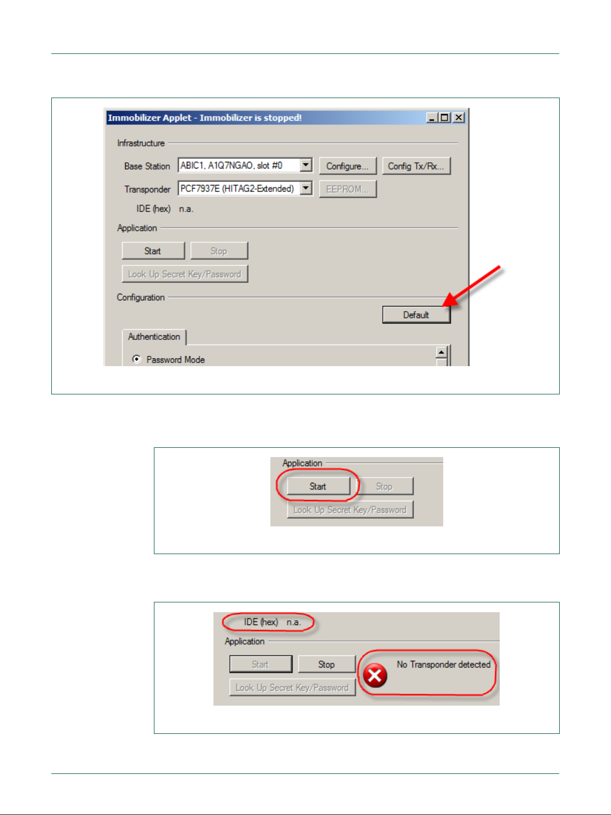
In this tutorial, the default settings are used. To apply them, just click on the DDeeffaauulltt button in the applet window (Fig 17).
Page 17
NXP Semiconductors
UM10276_1
TED-Kit 2 User Manual
All information provided in this document is subject to legal disclaimers.
© NXP B.V. 2010. All rights reserved.
User manual
Rev. 1.29 — 20 August 2010
17 of 79
Fig 17. Immobilizer default settings
Fig 18. Immobilizer starting
Fig 19. Immobilizer “No Transponder”
This sets the default values (for the selected transponder) for the authentication, transmission and reception parameters at once.
To start the immobilizer applet, one has to click the SSttaarrtt button only (Fig 18).
Now, the applet continuously tries to authenticate with HITAG2-Extended transponder in
the antenna’s field. If no transponder is in range, the Immobilizer window looks like Fig
19.
Page 18
NXP Semiconductors
UM10276_1
TED-Kit 2 User Manual
All information provided in this document is subject to legal disclaimers.
© NXP B.V. 2010. All rights reserved.
User manual
Rev. 1.29 — 20 August 2010
18 of 79
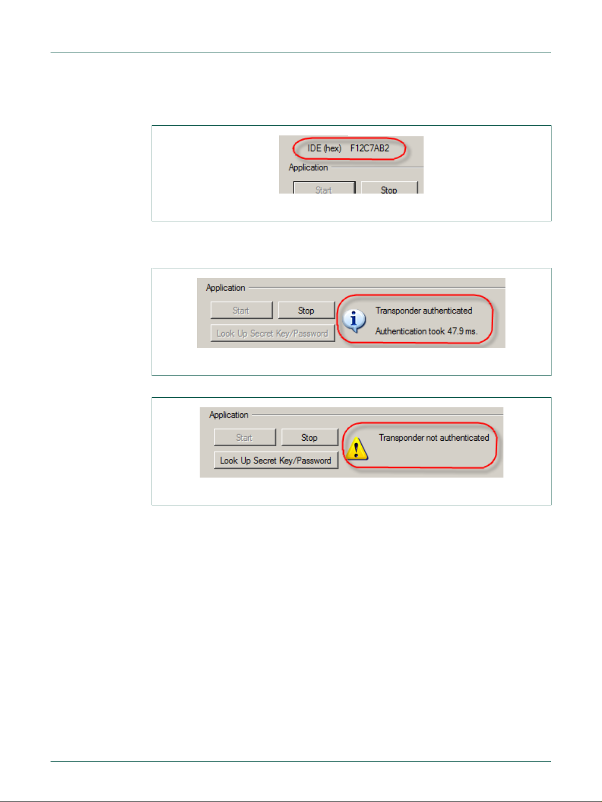
Fig 20. Immobilizer IDE
Fig 21. Immobilizer authenticated
Fig 22. Immobilizer authentication failed
As soon as a transponder is in range, the actual authentication sequence is started. The
transponder’s IDE is shown in the appropriate field (Fig 20).
Depending on the ingredients, the authentication may be successful or not. The current
state of the authentication is visualized in the status bar. For a successful authentication,
it looks like Fig 21.
For a failed authentication (e.g. bad passwords), the status bar looks like Fig 22.
The time required to run a complete authentication sequence is shown.
Note: In case the authentication sequence can be completed but the transponder
password is wrong, the authentication time is shown.
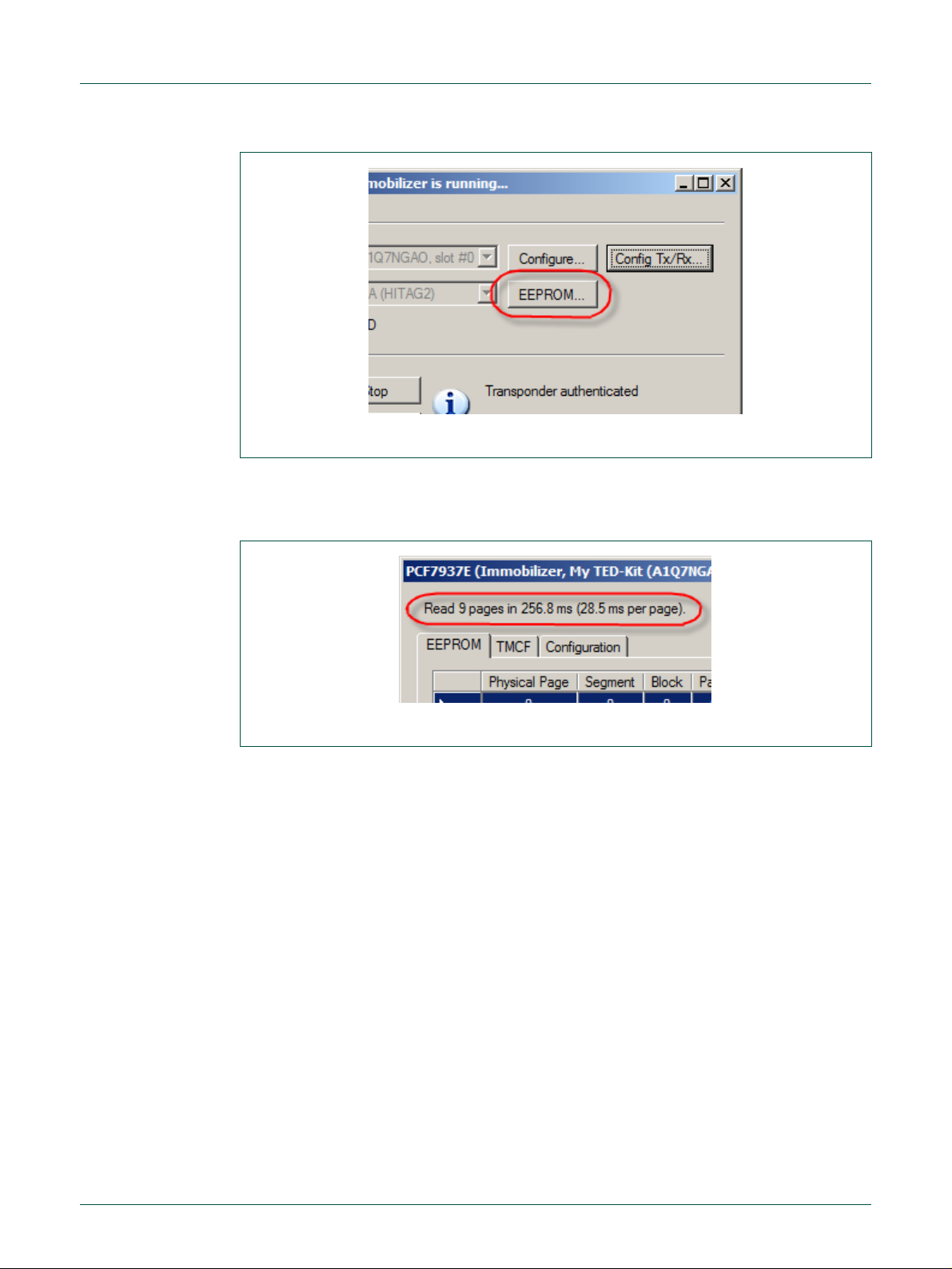
5.4.4 Exploring transponder memory
While the Immobilizer applet runs, the EEPROM content of the transponder in range can
be explored. To open the appropriate window, click the EEEEPPRROOMM…… button in the Immobilizer window (Fig 23).
Page 19
NXP Semiconductors
UM10276_1
TED-Kit 2 User Manual
All information provided in this document is subject to legal disclaimers.
© NXP B.V. 2010. All rights reserved.
User manual
Rev. 1.29 — 20 August 2010
19 of 79
Fig 23. Immobilizer EEPROM
Fig 24. EEPROM read timings
Note: This button is active only while the Immobilizer applet runs.
A new window opens showing 3 main parts. In the upper part of the window, the timings
regarding each reading operation are shown.
The middle part with the tabs shows the different views for the EEPROM content and its
configuration.
Note: In the EEPROM Tab only the memory pages currently visible are read from
the transponder. Scrolling to another section of the grid requires a short amount
of time until the actual content is shown. As long as the memory window is open
the content is refreshed multiple times per second.
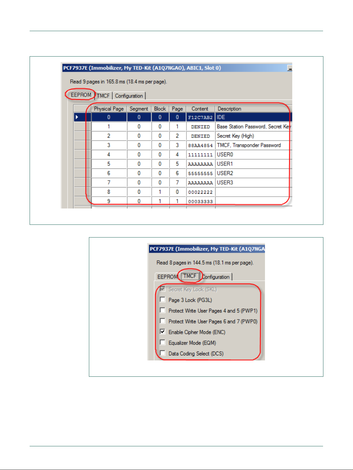
The EEEEPPRROOMM tab shows the memory grid for the physical page, segment, block and page
number, the content of that page and a description of the value if applicable (Fig 25).
Page 20
NXP Semiconductors
UM10276_1
TED-Kit 2 User Manual
All information provided in this document is subject to legal disclaimers.
© NXP B.V. 2010. All rights reserved.
User manual
Rev. 1.29 — 20 August 2010
20 of 79
Fig 25. EEPROM content
Fig 26. EEPROM TMCF
The TTMMCCFF tab shows the current content of the transponder modes settings (Fig 26).
In the picture shown above, the SKL bit is set and thus, cannot be altered anymore. Besides that, the ENC bit is set instructing the immobilizer to run ciphered authentication.
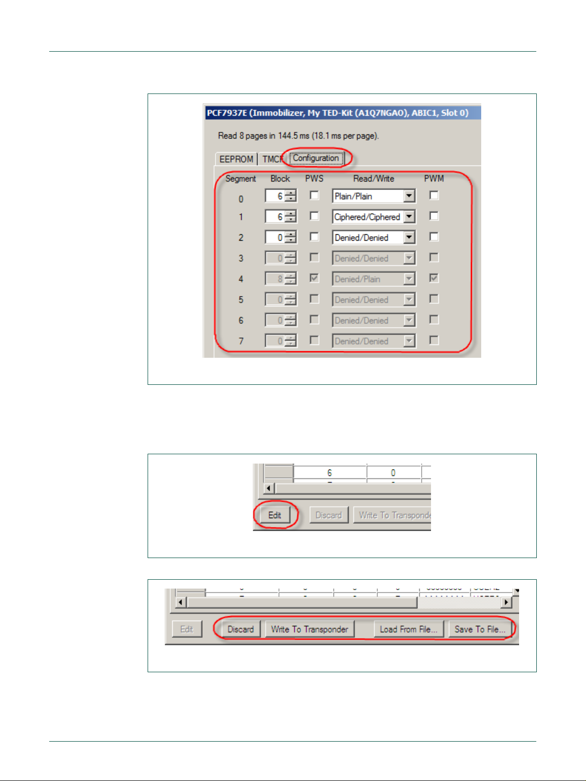
The CCoonnffiigguurraattiioonn tab shows the current memory configuration of the transponder. For
each Segment the size and the access mode for read and write operations can be defined. To prevent later manipulation the current settings for mode and size can be locked.
Thus later changes are not possible anymore (Fig 27).
Page 21
NXP Semiconductors
UM10276_1
TED-Kit 2 User Manual
All information provided in this document is subject to legal disclaimers.
© NXP B.V. 2010. All rights reserved.
User manual
Rev. 1.29 — 20 August 2010
21 of 79
Fig 27. EEPROM XMA configuration
Fig 28. EEPROM edit enable
Fig 29. EEPROM edit controls
For a detailed description please refer to the Transponder datasheet PCF7937EA.
5.4.5 Manipulating transponder memory
To modify the memory values, the edit mode of the EEPROM window has to be activated. To do so, click the EEddiitt button at the bottom of the window (Fig 28).
The refresh cycle will stop and the other 4 buttons at the bottom become active (Fig 29).
To enter a new value, just scroll to the page of interest and double-click inside the cell in
the column CCoonntteenntt and enter the new value. Modify any other page if required. To actually write the changes to the transponder, select WWrriittee TToo TTrraannssppoonnddeerr. To discard the
changes made, click Discard.
Page 22
NXP Semiconductors
UM10276_1
TED-Kit 2 User Manual
All information provided in this document is subject to legal disclaimers.
© NXP B.V. 2010. All rights reserved.
User manual
Rev. 1.29 — 20 August 2010
22 of 79
Fig 30. Immobilizer stopping
Note: The content of the EEPROM is shown always in hexadecimal notation. New
values entered are also required to be hexadecimal numbers.
To save the currently shown transponder memory to a file, select SSaavvee TToo FFiillee……. To load
a previously made memory snapshot click LLooaadd FFrroomm FFiillee…… and select the proper file.
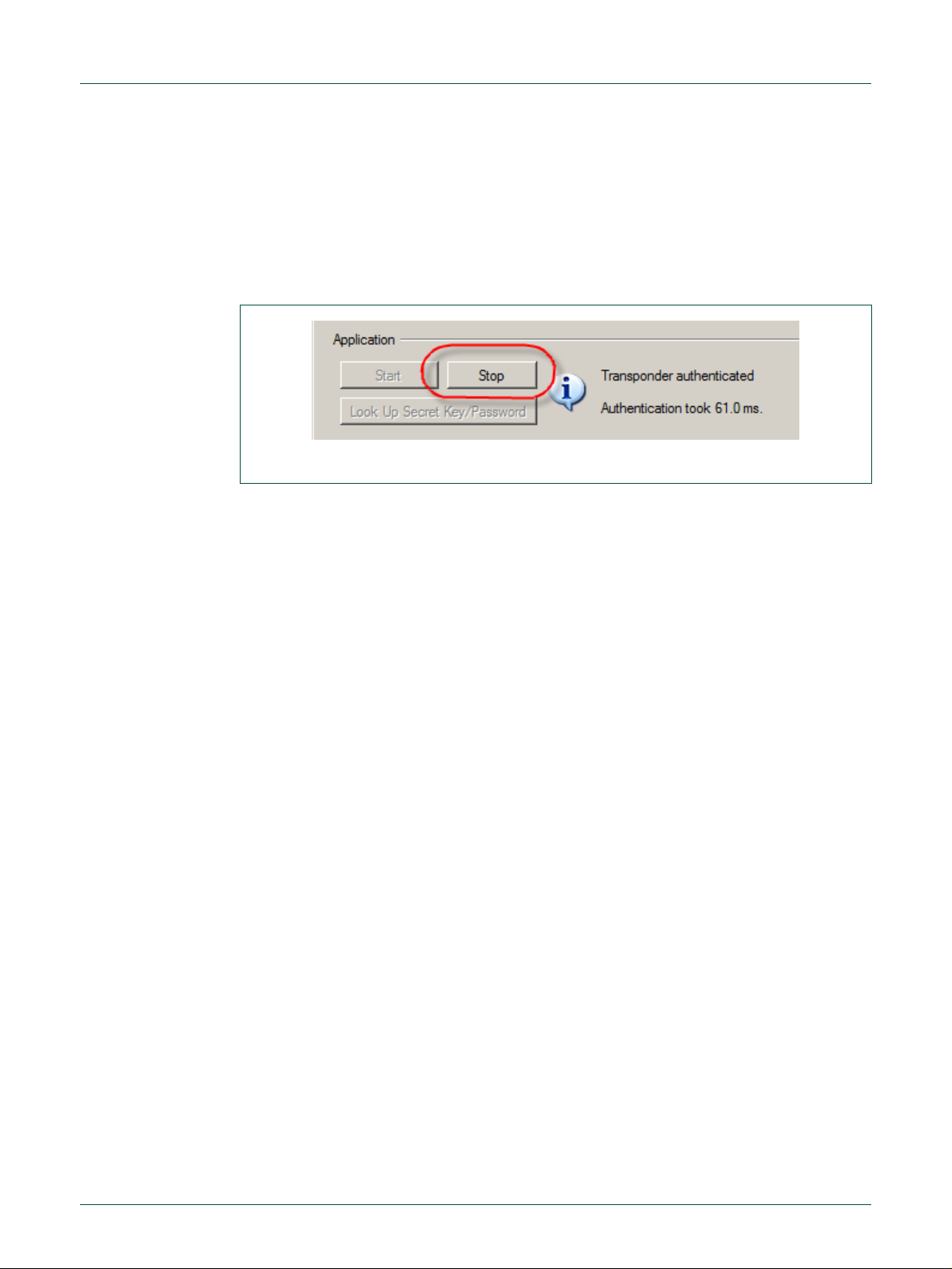
5.4.6 Stopping immobilizer
To stop the Immobilizer applet, the SSttoopp button has to be clicked (Fig 30).
5.5 Running RKE applet
To run the RKE applet, double click at one of the transponders of the desired family node
below the IImmmmoobbiilliizzeerr//RRKKEE or the IImmmmoobbiilliizzeerr//RRKKEE//PPKKEE node of the applet view. This will
set the default values for this transponder in advance (all settings can be changed afterwards though). The Immobilizer applet window appears first.
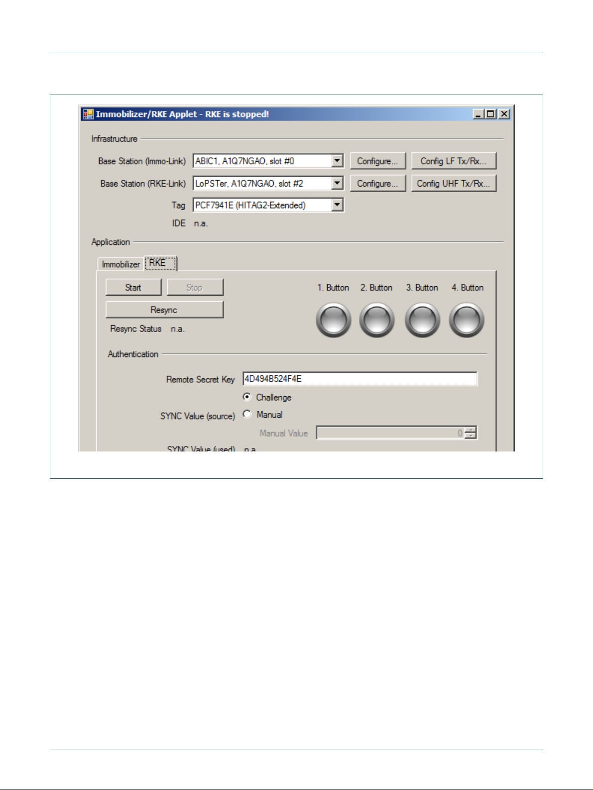
The RKE applet window appears if you click on the appropriate RRKKEE-tab in the application
section (Fig 31).
Page 23
NXP Semiconductors
UM10276_1
TED-Kit 2 User Manual
All information provided in this document is subject to legal disclaimers.
© NXP B.V. 2010. All rights reserved.
User manual
Rev. 1.29 — 20 August 2010
23 of 79
Fig 31. Immobilizer/RKE applet
The window contains two sections: The upper section shows the currently configured
infrastructure to run the RKE applet. The LF-IImmmmoo--LLiinnkk base station is needed for the
Tag-resynchronization. The UHF RRKKEE//PPKKEE--LLiinnkk base station is need for the one-way RKE
application itself. The Tag combo box allows choosing the transponder family.
The application section in the lower part of the window shows all necessary parts to run
RKE.
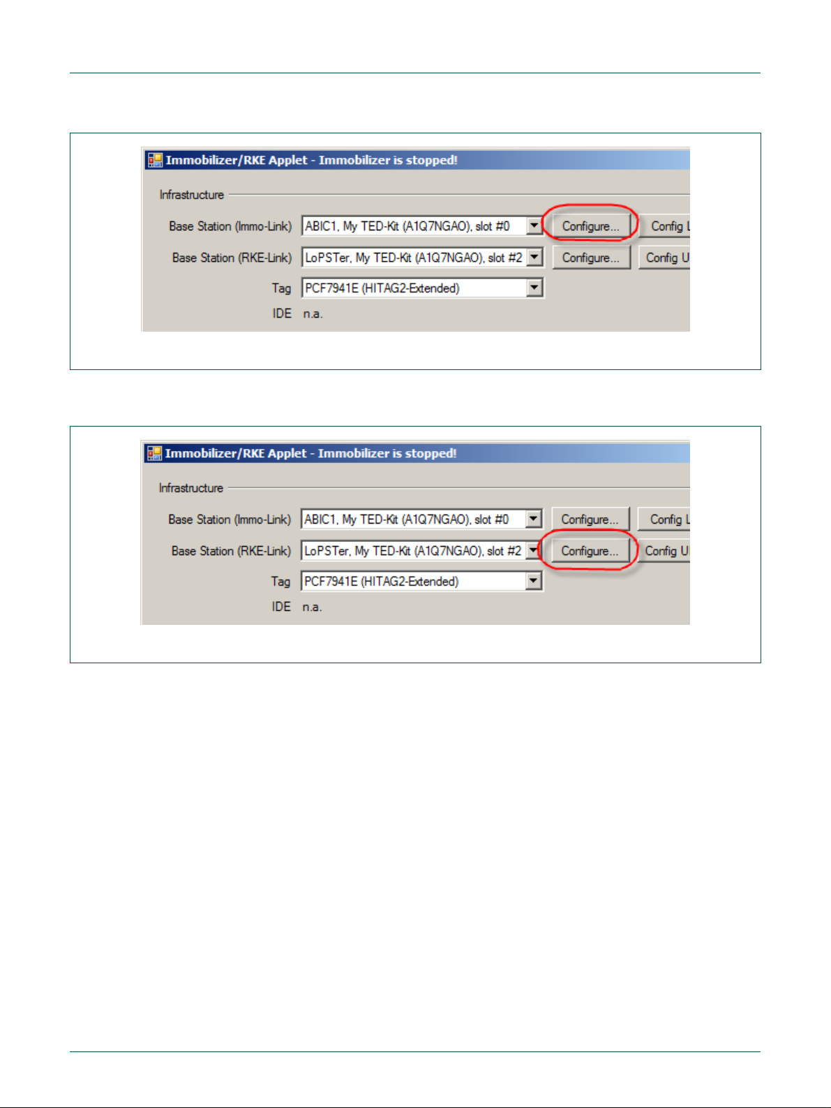
5.5.1 Configuring the ABIC1
Click on the CCoonnffiigguurree…… button of the Base Station for the Immo-Link (Fig 32) and the
window for ABIC1 configuration will appear. For a detailed description of the settings,
please refer to section 7.6, page 46.
Page 24
NXP Semiconductors
UM10276_1
TED-Kit 2 User Manual
All information provided in this document is subject to legal disclaimers.
© NXP B.V. 2010. All rights reserved.
User manual
Rev. 1.29 — 20 August 2010
24 of 79
Fig 32. Immobilizer/RKE configure ABIC1
Fig 33. Immobilizer/RKE configure LoPSTer
5.5.2 Configuring the LoPSTer
Click on the CCoonnffiigguurree…… button of the Base Station for the RKE/PKE-Link (Fig 33).
The LoPSTer configuration window will appear (Fig 34). The current settings of the LoPSTer board will be read out first. Many settings are possible but be careful if you do not
have much experience with this settings.
Note: The default settings read from the LoPSTer board already fit for typical applications.
Page 25

NXP Semiconductors
UM10276_1
TED-Kit 2 User Manual
All information provided in this document is subject to legal disclaimers.
© NXP B.V. 2010. All rights reserved.
User manual
Rev. 1.29 — 20 August 2010
25 of 79
Fig 34. LoPSTer configuration window
Fig 35. LoPSTer configuration loading
5.5.3 Configuration persistence
An entire package of settings can be loaded from a file by pressing the LLooaadd…… button (Fig
35). An appropriate LoPSTer configuration file is required; this might be a file saved as
back-up of the original configuration before a modification is done.
An entire package of settings can be stored to a file by pressing the SSaavvee…… button (Fig
36).
Page 26

NXP Semiconductors
UM10276_1
TED-Kit 2 User Manual
All information provided in this document is subject to legal disclaimers.
© NXP B.V. 2010. All rights reserved.
User manual
Rev. 1.29 — 20 August 2010
26 of 79
Fig 36. LoPSTer configuration saving
5.5.4 Transponder memory during RKE
During RKE application it is not possible to view the EEPROM window and inspect the
EEPROM content of the transponder. This can be achieved only with the IImmmmoobbiilliizzeerr
applet.
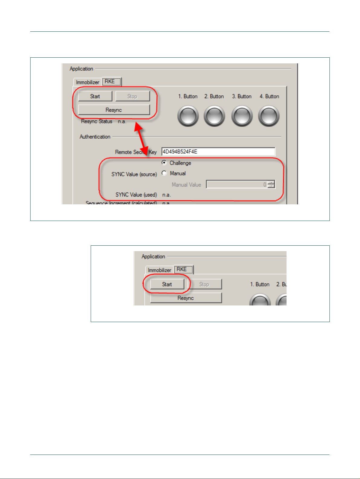
5.5.5 Resynchronization
Before you can start the RKE applet the tag must be resynchronized. Select a manual or
random value like shown below and press the RReessyynncc button (Fig 37). The resynchronization status can have 3 different states:
CChhaannggeedd --
nnoott cchhaannggeedd --
source.
Errrroorr -- An error occurred during synchronization. Check the tag type or the position and
distance to the LF antenna since resynchronization is done via the LF link.
the sync value has been changed successfully to the new value.
the sync value hasn’t been changed. Try again or modify the sync value
Page 27
NXP Semiconductors
UM10276_1
TED-Kit 2 User Manual
All information provided in this document is subject to legal disclaimers.
© NXP B.V. 2010. All rights reserved.
User manual
Rev. 1.29 — 20 August 2010
27 of 79
Fig 37. RKE resynchronization
Fig 38. RKE starting
5.5.6 Starting RKE
Start the RKE application by pressing the SSttaarrtt button (Fig 38).
After the application was started any button on the tag can be pressed and the corresponding LED display will light up in the GUI like shown below. Additional the polling status will be displayed and should be OOKK.
All exchanged values during the communication like the SSYYNNCC vvaalluuee, the calculated and
received SSeeqquueennccee IInnccrreemmeenntt as well as the calculated and received SSeeqquueennccee RReessppoonnssee
are displayed (Fig 39).
Page 28

NXP Semiconductors
UM10276_1
TED-Kit 2 User Manual
All information provided in this document is subject to legal disclaimers.
© NXP B.V. 2010. All rights reserved.
User manual
Rev. 1.29 — 20 August 2010
28 of 79
Fig 39. RKE polling
Fig 40. RKE stopping
5.5.7 Stopping RKE
Stop the RKE application by pressing the SSttoopp button ().
5.6 Running PKE applet
To run the PKE applet, double click at one of the transponders of the desired family node
below the IImmmmoobbiilliizzeerr//RRKKEE//PPKKEE node of the applet view. This will set the default values
for this transponder in advance (all settings can be changed afterwards though). The
Immobilizer applet window appears first.
The PKE applet window appears if you click on the appropriate PPKKEE-tab in the application
section (Fig 41).
Page 29

NXP Semiconductors
UM10276_1
TED-Kit 2 User Manual
All information provided in this document is subject to legal disclaimers.
© NXP B.V. 2010. All rights reserved.
User manual
Rev. 1.29 — 20 August 2010
29 of 79
Fig 41. PKE starting
The window contains two sections: The upper section shows the currently configured
infrastructure to run the PKE applet. The LF-IImmmmoo--LLiinnkk base station is needed as uplink
channel. The UHF RRKKEE//PPKKEE--LLiinnkk base station is needed as downlink channel. The Tag
window allows choosing the Transponder family.
The application section in the lower part of the window shows all necessary parts to run
different PKE-applications.
5.6.1 Configuring the ABIC1
For a detailed description of the settings, please refer to section 6.6.1.
5.6.2 Configuring the LoPSTer
For a detailed description of the settings, please refer to section 6.6.2.
5.6.3 Transponder memory during PKE
During PKE application it is not possible to open the EEPROM window. If you want to do
this select the appropriate Tag from the Immobilizer tree node and press the enabled
M button.
EEEEPPRROOM
5.6.4 Tag scanning
After pressing the SSccaann TTaaggss button all available tags in range will be scanned and the
appropriate IDE will appear in the list box below the button (Fig 42).
Page 30

NXP Semiconductors
UM10276_1
TED-Kit 2 User Manual
All information provided in this document is subject to legal disclaimers.
© NXP B.V. 2010. All rights reserved.
User manual
Rev. 1.29 — 20 August 2010
30 of 79
Fig 42. PKE tag scanning
a. starting
b. stopping
Fig 43. PKE cyclic authentication
5.6.5 Cyclic PKE authentication
Select one of the available tags. Enabling the CCyycclliicc AAuutthheenntt checkbox performs a cyclic
authentication using the HITAG2 crypto algorithm. The exchanged authentication values
will be displayed like shown in Fig 43a.
Disabling the CCyycclliicc AAuutthheenntt checkbox stops the cyclic authentication. Exchanged values
are no longer available (Fig 43b).
Page 31

NXP Semiconductors
UM10276_1
TED-Kit 2 User Manual
All information provided in this document is subject to legal disclaimers.
© NXP B.V. 2010. All rights reserved.
User manual
Rev. 1.29 — 20 August 2010
31 of 79
Fig 44. PKE single authentication
5.6.6 Single PKE authentication
Beside the cyclic authentication, also single step authentication can be performed after
each press on the SSiinnggllee AAuutthheenntt button. The exchanged authentication values will be
displayed like shown in Fig 44.
5.6.7 Cyclic RSSI
Select one of the available Tags. Enabling the CCyycclliicc RRSSSSII checkbox performs a cyclic
RSSI measurement of all three axes, and calculates the sum signal as squared vector
length (squared geometric mean) V2 = X2 + Y2 + Z2. Each single value will dynamically be
displayed in a separate progress bar (Fig 45).
Page 32

NXP Semiconductors
UM10276_1
TED-Kit 2 User Manual
All information provided in this document is subject to legal disclaimers.
© NXP B.V. 2010. All rights reserved.
User manual
Rev. 1.29 — 20 August 2010
32 of 79
Fig 45. PKE cyclic RSSI
Fig 46. PKE cyclic RSSI stopped
Disabling the CCyycclliicc RRSSSSII checkbox stops the RSSI measurement. The RSSI values are
no longer available thus the progress bars are empty (Fig 46).
Select different ADC resolutions for the RSSI measurements using the AADDCC RReessoolluuttiioonn
combo box. This setting is only enabled when the RSSI measurement is disabled (Fig
47).
Page 33

NXP Semiconductors
UM10276_1
TED-Kit 2 User Manual
All information provided in this document is subject to legal disclaimers.
© NXP B.V. 2010. All rights reserved.
User manual
Rev. 1.29 — 20 August 2010
33 of 79
Fig 47. PKE RSSI ADC
Fig 48. PKE battery voltage starting
5.6.8 Cyclic V
Select one of the available Tags. Enabling the CCyycclliicc CChheecckk checkbox performs a cyclic
measurement of the Tag battery voltage. The voltage will be displayed like in Fig 48.
Bat
Select different loads for the Tag battery voltage measurement using the MMeeaassuurreemmeenntt
d combo box. This setting can be changed during a running measurement (Fig 49a).
LLooaad
Page 34

NXP Semiconductors
UM10276_1
TED-Kit 2 User Manual
All information provided in this document is subject to legal disclaimers.
© NXP B.V. 2010. All rights reserved.
User manual
Rev. 1.29 — 20 August 2010
34 of 79
a. Selecting load
c. stopping
Fig 49. PKE battery voltage load/stop
Fig 50. Figure title here
Disabling the CCyycclliicc CChheecckk checkbox stops the Tag battery voltage measurement. The
current voltage is no longer available (Fig 49b).
5.7 Getting Help
The HHeellpp menu of the GUI’s main window contains links to documents and the AAbboouutt……
window (Fig 50).
The documents are PDFs and thus, require proper PDF reading software installed. The
… window shows the version numbers of the software package, its components as
AAbboouutt…
well as the currently plugged-in TED-Kit 2 boxes (Fig 51).
Page 35

NXP Semiconductors
UM10276_1
TED-Kit 2 User Manual
All information provided in this document is subject to legal disclaimers.
© NXP B.V. 2010. All rights reserved.
User manual
Rev. 1.29 — 20 August 2010
35 of 79
Fig 51. TED-Kit 2 about window
With CCooppyy ttoo CClliippbbooaarrdd, this information can be easily copied in a document or an Email
and will help the support team to analyze the issues reported.
5.8 Updating the firmware
Each time the GUI is started, it checks the firmware version of each of the connected
TED-Kit 2 boards. This check also happens if a board is plugged in while the GUI already
runs. The check compares the firmware version running on the board with the one copied
to the PC during the installation procedure of the software package.
In case of a mismatch, a dialog like in Fig 52 is shown.
Page 36

NXP Semiconductors
UM10276_1
TED-Kit 2 User Manual
All information provided in this document is subject to legal disclaimers.
© NXP B.V. 2010. All rights reserved.
User manual
Rev. 1.29 — 20 August 2010
36 of 79
Fig 52. Firmware update dialog
It explains that the TED-Kit 2 “My TED-Kit” with serial number A1Q55A99 is running
firmware version 1.13 while the support firmware is version 1.19.
Clicking the UUppddaattee button will start the update procedure which takes 10...15 seconds.
Clicking the CCaanncceell button will not do anything with the TED-Kit 2. To avoid any conflicts
between the GUI and this TED-Kit 2, it is deactivated and cannot be used in the GUI. The
hardware view will show it grayed out.
To reactivate the TED-Kit 2, unplug it from the PC and plug it in again or restart the GUI
and actually update the firmware.
Note: To ensure each TED-Kit 2 runs exactly the firmware which is known by the
GUI, an up- or down(!)grade of the firmware version may take place.
To find the firmware currently supported by the GUI, look in the Firmware folder inside
the installation folder:
[TED-Kit 2 Installation]/Firmware
It contains files with names like 03-001019-r.hex. This is the release [r] firmware version
001.019 (or just 1.19) for main board revision 03 (or just 3).
5.9 Using unsupported hardware
In case of a very old main board together with a very new GUI software (or vice versa), a
hardware support conflict might happen. The reason for that is that an old GUI version is
not certified to work with a newer main board revision or a new GUI does not support an
outdated main board anymore. A dialog like in Fig 53 is shown:
Page 37

NXP Semiconductors
UM10276_1
TED-Kit 2 User Manual
All information provided in this document is subject to legal disclaimers.
© NXP B.V. 2010. All rights reserved.
User manual
Rev. 1.29 — 20 August 2010
37 of 79
Fig 53. TED-Kit 2 unsupported hardware dialog
The current instance of the GUI is not certified to work with (the outdated) main board
revision 1 and thus, disables the TED-Kit 2.
To solve this conflict, either update to the latest version of the TED-Kit 2 software or get
the latest version of the main boards or install an older version of the TED-Kit 2 software
which supports your main boards.
6. Reference
6.1 Menu bar
6.1.1 Board
To see what hardware is supported by the GUI, look in the Firmware folder of the installation folder. It contains files with names like 03-001019-r.hex. The first number indicates
the hardware revision supported (01, 02 …). Only boards with hardware revisions found
in this folder can be used together with this GUI.
The section explains all elements of the GUI, what they do and when they can be used.
The elements are organized in groups; each group represents one module (e.g. window)
of the interface.
The menu bar of the main window contains the following menus and sub-menus:
This menu contains the functions for the TED-Kit 2 board and its XBoards.
TED-Kit 2 Status…
Opens the TED-Kit 2 status window for the currently in the hardware view selected TEDKit 2 or for the TED-Kit 2 of the currently selected XBoard. The menu is disabled if no
TED-Kit 2 or no XBoard is selected. For details of this win 7.5, page
43.
Identify TED-Kit 2
Flashes the 4 status LEDs of the currently in the hardware view selected TED-Kit 2 or for
the TED-Kit 2 of the currently selected XBoard. The menu is disabled if no TED-Kit 2 or
no XBoard is selected.
Debug TED-Kit 2 Firmware
Shows the type of the firmware of all currently connected and activated TED-Kit 2 box. A
checkmark at the left side of the menu entry indicates that the debug version of the firmware is currently used by all TED-Kit 2 boxes. No checkmark indicates the release version of the firmware is used.
Clicking the menu will toggle the firmware type and run the firmware update sequence for
all currently connected and active TED-Kit 2 boxes.
Page 38

NXP Semiconductors
UM10276_1
TED-Kit 2 User Manual
All information provided in this document is subject to legal disclaimers.
© NXP B.V. 2010. All rights reserved.
User manual
Rev. 1.29 — 20 August 2010
38 of 79
Configure & Monitor XBoard…
Opens the Configuration and monitoring window for the currently in the hardware view
selected XBoard. The menu is disabled if no XBoard is selected. For details of this window, refer to section 6.6.
6.1.2 Window
The menu contains all functions to control the currently opened windows of the TED-Kit 2
GUI. Only the first three menu items are fixed. For each window opened, a new entry is
created and appended below the first three items (and removed if the window is closed).
This will make access to each window simpler, especially if many windows are opened at
once.
Tile/Horizontal
Arranges all windows currently open in style Tile/Horizontal.
Tile/Vertical
Arranges all windows currently open in style Tile/Vertical.
Cascade
Arranges all windows currently open in a cascade style.
6.1.3 Help
The help menu contains links to certain documents which are installed along with the
software. These documents are in Adobe’s PDF format and thus, a proper PDF viewer
(e.g. Adobe Reader) needs to be installed on the system in order to read them.
User’s Manual
Opens this document for reading.
HITAG2
Opens the HITAG2 product profile for reading.
HITAG2+
Opens the HITAG2+ product profile for reading.
HITAG2+EE
Opens the HITAG2+EE product profile for reading.
HITAG2-Extended
Opens the HITAG2-Extended product profile for reading.
HITAG-Pro
Opens the HITAG-Pro product profile for reading.
ABIC1
Opens the ABIC1 product profile for reading.
About…
Opens a window showing all version information of the GUI software and its components
used (libraries, .NET environment and device driver) as well as all data collectable of the
currently connected TED-Kit 2 boxes and their XBoards.
The data can be easily copied to the system clipboard by clicking CCooppyy ttoo CClliippbbooaarrdd. To
close the dialog, click OOKK.
Page 39

NXP Semiconductors
UM10276_1
TED-Kit 2 User Manual
All information provided in this document is subject to legal disclaimers.
© NXP B.V. 2010. All rights reserved.
User manual
Rev. 1.29 — 20 August 2010
39 of 79
6.2 Hardware view
The hardware view visualizes all currently connected TED-Kit 2 boxes along with their
XBoards and antenna configurations. For each TED-Kit 2, a tree like shown below is
created:
TED-Kit 2 Main Board TED-Kit 2 custom name and serial number
o XSlot #0 XBoard name and antenna(s)
o XSlot #1 XBoard name and antenna(s)
o XSlot #2 XBoard name and antenna(s)
o XSlot #3 XBoard name and antenna(s)
A double-click at the TED-Kit 2 node opens the TED-Kit 2 status window. Double-clicking
at any XSlot opens the appropriate configuration & monitoring window.
If a TED-Kit 2 is deactivated due to an incompatible hardware revision or unsupported
firmware, its sub tree is grayed out and cannot be selected/clicked.
6.3 Applet view
The applet view visualizes all currently available applets along with the supported transponder families and types. To open an applet window, the transponder type intended to
use out of the applet node has to be double-clicked.
Several or all nodes of the applet view become inactive if no (more) hardware resources
are available to run a certain application. To activate the (parts of the) applet view again,
running applets must be stopped or more hardware has to be added. This can be done
by either plug-in additional (properly configured) TED-Kit 2 boxes or add more appropriate XBoards to the currently available TED-Kit 2 boards.
6.4 Message view
The message view shows all messages issued by all components of the software. That
includes the GUI, the API library, the device drivers and the TED-Kit 2 firmware itself.
Mainly, these are communication data send between the GUI to the firmware of the TEDKit 2 box and back.
It is placed in the lower right part of the TED-Kit 2 main window (see Fig 54). Dragging
the upper border allows changing its vertical size (down to 0 making it disappear).
Page 40

NXP Semiconductors
UM10276_1
TED-Kit 2 User Manual
All information provided in this document is subject to legal disclaimers.
© NXP B.V. 2010. All rights reserved.
User manual
Rev. 1.29 — 20 August 2010
40 of 79
Fig 54. Message view
Fig 55. Message view details
Several tabs are used to organize the messages and make reading them simpler. Two
tabs always exist: The leftmost tab named GGeenneerraall shows status messages from the GUI
software itself.
Right to the GGeenneerraall tab is the SSccaannnneerr tab. The messages shown here represent the
commands used by the GUI to scan for (new) TED-Kit 2 boxes connected to the host PC.
Most important for the user are the tabs dynamically created, one for each TED-Kit 2.
Each of them is named with the serial number and the custom name (if applicable). A
typical view for one connected TED-Kit 2 box might look like Fig 55.
Page 41

NXP Semiconductors
UM10276_1
TED-Kit 2 User Manual
All information provided in this document is subject to legal disclaimers.
© NXP B.V. 2010. All rights reserved.
User manual
Rev. 1.29 — 20 August 2010
41 of 79
Fig 56. Message view context menu
New messages are always appended at the beginning of the list. The message view
ensures that always the latest messages are shown. The message view holds 1000
messages. If this limit is reached, the oldest messages are discarded.
The message list shows for each message the command and its parameters and when it
was send. The triangle to the left can be clicked to show more detailed information such
as the status code of executing the command, trace data showing what the TED-Kit 2
firmware actually did and the result of the operation.
Red rows indicate that an error happened during the execution of the command.
Note: The trace information with detailed data about the execution steps done by
the TED-Kit 2 firmware is available only if the DEBUG version of the firmware is
running.
6.4.1 Context menu
The message view offers a context menu available at right-clicking directly inside the
message view.
For each tab, the data can be selected, copied or cleared with command from the context
menu available while right-clicking in the message view area:
Select All
Selects all the messages/text shown in the current message view.
Copy
Copies the current selection of messages/text to the system clipboard.
Clear All
Clears the content of the currently visible message view.
Pause Updates
No more text/messages are added to the currently active view. The messages are
cached and added immediately after Pause Updates is deactivated.
Page 42

NXP Semiconductors
UM10276_1
TED-Kit 2 User Manual
All information provided in this document is subject to legal disclaimers.
© NXP B.V. 2010. All rights reserved.
User manual
Rev. 1.29 — 20 August 2010
42 of 79
Show Errors Only
Filters all messages which status code OK and drops them. This is very useful for error
analysis because only erroneous commands are shown.
Note: All commands of the context menu affect only the currently visible message
view.
6.4.2 Logging
All activities shown in the message view are also logged in a file. This file contains all
messages for one TED-Kit 2 session. If the GUI is restarted, the file is emptied and logging starts from the beginning.
The log file can be found at
[Current User’s Application Data]\NXP Semiconductors\TED-Kit 2\[Version]\log.xml
6.5 TED-Kit 2 status window
The TED-Kit 2 status window shows all information about a TED-Kit 2 and its XBoards.
To open the window, double-click the desired TED-Kit 2 node in the hardware view or
select the TED-Kit 2 node and click the menu BBooaarrddTTEEDD--KKiitt 22 SSttaattuuss…….
Page 43

NXP Semiconductors
UM10276_1
TED-Kit 2 User Manual
All information provided in this document is subject to legal disclaimers.
© NXP B.V. 2010. All rights reserved.
User manual
Rev. 1.29 — 20 August 2010
43 of 79
Fig 57. TED-Kit 2 status window
Name
Auto Update
Description
TED-Kit 2
Serial Number
✗
The main board’s unique serial number.
Board Revision
✗
The revision of the main board hardware.
Custom Name
✗
The TED-Kit 2’s custom name or nn..aa.. if not set.
Rename
n/a
Opens the rename dialog which allows setting or changing
the TED-Kit 2 custom name.
Identify
n/a
Flashes the status LEDs at this TED-Kit 2.
Firmware Version
✗
The version of the firmware currently running.
As long as the window is shown, some of the items shown are continuously updated
reflecting their changes.
The information and actions available are shown in Table 2.
Table 2. TED-Kit 2 status window items
Page 44

NXP Semiconductors
UM10276_1
TED-Kit 2 User Manual
All information provided in this document is subject to legal disclaimers.
© NXP B.V. 2010. All rights reserved.
User manual
Rev. 1.29 — 20 August 2010
44 of 79
Name
Auto Update
Description
Firmware Type
✗
The type of the firmware currently running (either RELEASE or DEBUG).
Firmware Code
✗
The firmware code, 0 indicates the firmware works together with the TED-Kit 2 GUI and library.
Memory Available
✓
The RAM currently available at the TED-Kit 2 µController
(in bytes).
Max Block Size
Available
✓
The size of the largest continuous free RAM block available (in bytes).
Supply Voltage
✓
The board’s supply voltage (in Volts).
Clock Frequency
✗
The board’s clock frequency (in MHz).
XBoard
Type
✗
This XBoard’s type (e.g. ABIC1) or EEmmppttyy if not XBoard is
in this XSlot.
Antenna
LF ✗ XBoard is connected to a LF antenna.
UHF
✗
XBoard is connected to a UHF antenna.
Ability
Transmit
✗
XBoard is capable of transmitting data (via an antenna).
Receive
✗
XBoard is capable of receiving data (via an antenna).
Interfaces
SPI ✗ The XBoard has a SPI interface.
I2C ✗ The XBoard has an I2C interface.
GPIO
✗
The XBoard has a GPIO interface.
LIN ✗ The XBoard has a LIN interface.
I/O
Interrupt Output
✗
The XBoard can interrupt the TED-Kit 2 µController.
Analog Input
✗
The TED-Kit 2 µController can feed analogue signals into
this XBoard.
Analog Output
✗
The XBoard can feed analogue signals into the TED-Kit 2
µController.
Disabled
✗
The XBoard is disabled due to resource conflicts at the
TED-Kit 2 main board (e.g. it is equipped with 3 ABIC1
XBoards one is disabled).
6.5.1 Set TED-Kit 2 custom name
Each TED-Kit 2 box can have its own customized name. The status window’s RReennaammee
button will open a dialog allows setting, changing or removing the custom name of the
TED-Kit 2 box (Fig 58).
Page 45

NXP Semiconductors
UM10276_1
TED-Kit 2 User Manual
All information provided in this document is subject to legal disclaimers.
© NXP B.V. 2010. All rights reserved.
User manual
Rev. 1.29 — 20 August 2010
45 of 79
Fig 58. TED-Kit 2 rename dialog
To set or change it, type the new name and click OK. To delete it, remove all characters
from the dialog’s text box and click OK.
Note: Valid names consist of 0 to 12 characters in the US-ASCII range 20
7E
.
hex
The main advantage is to easily distinguish between several connected TED-Kit 2 boxes
because a name is easier to recognize than a serial number. To avoid any confusion if
there a multiple TED-Kit 2 boxes are connected, one can put stickers with the custom
name at the boxes.
6.5.2 Identify TED-Kit 2
This function is also designed to simplify handling of multiple TED-Kit 2 boxes. Clicking
this button will flash the four status LEDs of the selected TED-Kit 2 box for a few
seconds.
6.6 XBoard configuration window
Currently, two XBoards are supported by the TED-Kit 2 GUI: ABIC1 and LoPSTer. Thus,
two different configuration windows exist. Nevertheless, they have some elements in
common:
The largest part of this window always shows the current settings and status information.
Note: All changes made to the settings are effective immediately. If the window is
opened, it immediately reflects the current settings and status of the XBoard.
As long as the window is open, the status information for the antenna demodulator are
continuously read and updated.
hex
to
Status Information
On top of the configuration window, the status information field shows what application is
currently using this XBoard. The communication status indicates whether data can be
exchanged with the XBoard (OOKK) or not (FFaaiilluurree).
Configuration persistence
Each XBoard configuration window can save and load hardware settings to and from
files. The LLooaadd…… button allows to load a previously saved set of settings. The SSaavvee……
button saves the currently visible settings to a file.
The default storage location is:
[Current User’s Application Data]\NXP Semiconductors\TED-Kit 2\[Version]
Page 46

NXP Semiconductors
UM10276_1
TED-Kit 2 User Manual
All information provided in this document is subject to legal disclaimers.
© NXP B.V. 2010. All rights reserved.
User manual
Rev. 1.29 — 20 August 2010
46 of 79
For a user Homer running version 3.1.0 of the GUI, this might resolve on a typical Windows installation to:
C:\Documents and Settings\Homer\Application Data\NXP Semiconductors\TED-Kit 2\3.1.0
6.6.1 ABIC1 configuration window
The configuration and monitoring window allows to set the ABIC1 XBoard configuration
as wells as to monitor several status information. To open the window, select the desired
XBoard from the hardware view tree and select from the menu BBooaarrddCCoonnffiigguurree && MMoonnii--
ttoorr XXBBooaarrdd…
button in the applet window.
The window consists of three parts. The upper part shows some status information, the
middle part allows to set default values depending on a transponder family and the lower
part gives direct access to all the ABIC1 specific settings and status information.
Default settings
The default settings for an ABIC1 XBoard depend on the transponder family which will be
used with this XBoard. Thus, setting default values involves two steps:
1. Selecting the desired transponder family.
2. Clicking the DDeeffaauulltt button.
… or double-click the tree node of the desired XBoard or click the CCoonnffiigguurree……
If this window is opened from the applet window via CCoonnffiigguurree……, the already chosen
transponder family is preset for the default button.
6.6.2 LoPSTer configuration window
The configuration and monitoring window allows to set the LoPSTer XBoard configuration as wells as to monitor several status information. To open the window, select the
desired XBoard from the hardware view tree and select from the menu BBooaarrddCCoonnffiigguurree
&& MMoonniittoorr XXBBooaarrdd…
… button in the applet window.
ffiigguurree…
… or double-click the tree node of the desired XBoard or click the CCoonn--
The “configure and monitoring” window consists of three parts. The upper part shows
some status information, the middle part allows to load and save configurations.
The lower part gives direct access to all the LoPSTer specific settings and status information. When opening the LoPSTer configuration window the current settings from the
chip will be read out first. Many settings are possible but be careful if you do not have
much experience with this settings. Thus it is recommended to use the Load/Save features.
6.7 Immobilizer applet window
To open this window, the appropriate tree node of the desired transponder family below
the Immobilizer tree node of the applet view has to be double-clicked.
The window itself consists of three parts. The upper part defines the infrastructure of the
applet by means of what base station and what transponder family is being used.
The middle part controls the immobilizer application itself and provides status information
of the authentication between base station and transponder.
The lower part defines all the settings for the communication and authentication between
base station and transponder.
Page 47

NXP Semiconductors
UM10276_1
TED-Kit 2 User Manual
All information provided in this document is subject to legal disclaimers.
© NXP B.V. 2010. All rights reserved.
User manual
Rev. 1.29 — 20 August 2010
47 of 79
Infrastructure
The infrastructure required for the immobilizer applet consists of one base station and
one transponder.
The base station selector offers all XBoards equipped with an ABIC1 base station. The
one selected will be used for the application. The configure button right to the selector
opens the ABIC1 configuration window for the currently selected XBoard (see 7.6: ABIC1
Configuration Window, page 46).
The transponder selector allows selecting the desired transponder family. This selection
mainly effects the look of the EEPROM window as well as what values are set by clicking
at the Default button of the configuration section of this window. The selected transponder family is also preset for the ABIC1 configuration window (if opened from this window).
The IDE shows the transponder identification if the application is started and a transponder is in range. The IDE is shown as soon as a transponder is in range regardless of
its family or if it can be authenticated.
Application
The controls for the application are
t – starts the immobilizer application.
SSttaarrt
p – stops the immobilizer application.
SSttoop
LLooookk UUpp SSeeccrreett KKeeyy//PPaasssswwoorrd
tion mode from the local transponder data base and restores the values into the Immobilizer applet window for the transponder currently in range. This function is available only
if a transponder is in range, the authentication fails and the IDE can be found in the local
transponder data base. A transponder is added automatically to this data base after it
has been successfully authenticated. Only the last set of successful authentication data
is stored for each transponder.
Configuration
The lower part of the applet window contains the controls to manipulate all the communication and authentication settings. The content of this part of the window depends on the
selected transponder family. For a detailed description of each of the settings, please
refer to the appropriate ABIC1 and transponder data sheet.
The DDeeffaauulltt button will set the default values for all settings available depending on the
currently selected transponder family.
6.7.1 HITAG-Pro 2 distance
A special functionality of the HITAG-Pro 2 is the ability to save distance records in a special way. If a HITAG-Pro 2 transponder is selected, a second tab is shown in the configuration section of the Immobilizer applet window (Fig 59).
d – Looks up the secret key or password and the authentica-
Page 48

NXP Semiconductors
UM10276_1
TED-Kit 2 User Manual
All information provided in this document is subject to legal disclaimers.
© NXP B.V. 2010. All rights reserved.
User manual
Rev. 1.29 — 20 August 2010
48 of 79
Fig 59. Distance record panel
Fig 60. Distance record new
The table contains the 7 current records and the 8th record which is used as internal log.
Initially, no records are read. In order to get the current values, click RReeaadd RReeccoorrddss. To
create a new distance record, click NNeeww RReeccoorrdd and fill the data in the upcoming dialog
(Fig 60).
VVaalluuee --
DDaattee --
SSeennd
The distance value of the new record.
The date of the distance record, today’s date is preselected.
d - to actually send the data to the transponder (the record table will be re-read im-
mediately)
l -- to close the dialog without sending.
CCaanncceel
Page 49

NXP Semiconductors
UM10276_1
TED-Kit 2 User Manual
All information provided in this document is subject to legal disclaimers.
© NXP B.V. 2010. All rights reserved.
User manual
Rev. 1.29 — 20 August 2010
49 of 79
6.8 RKE applet window
To open this window, the appropriate tree node of the desired transponder family below
the Immobilizer/RKE or Immobilizer/RKE/PKE tree node of the applet view has to be
double-clicked.
The window itself consists of two sections. The upper section defines the infrastructure of
the applet by means of what base stations and what transponder family is being used.
The RKE tab of the lower section consists of the RKE application.
Infrastructure
Shows the currently configured infrastructure used by the RKE applet. The LF-IImmmmoo--LLiinnkk
base station is needed for the tag resynchronization. The UHF RRKKEE//PPKKEE--LLiinnkk base station
is needed for the one-way RKE application itself. The TTaagg is the transponder family being used.
RKE Application
Shows all necessary controls to run the RKE application. The controls for the application
are:
t – starts the RKE application.
SSttaarrt
p – stops the RKE application.
SSttoop
c – writes a new SYNC value into the tag. The new SYNC value can be given ei-
RReessyynnc
ther manually or by a random generator. In both cases the new value will be displayed.
RReessyynncc ssttaattuus
CChhaannggeed
nnoott cchhaannggeedd --
s:
d - the new SYNC value has been changed successfully to the new value.
the SYNC value hasn’t been changed. Select a new Manual value or
choose Challenge to get a new value.
- An error occurred during synchronization. Check the Tag type or the position and
EErrrroorr -
distance to the antenna.
RKE settings
To set a new SYNC value to be able to run a RKE application a valid Remote Secret Key
and the SYNC value itself has to be given. The source of the SYNC value can be chosen
manually or by a random generator.
6.9 PKE applet window
To open this window, the appropriate tree node of the desired transponder family below
the Immobilizer/RKE/PKE tree node of the applet view has to be double-clicked.
The window itself consists of two sections. The upper section defines the infrastructure of
the applet by means of what base stations and what transponder family is being used.
The PKE tab of the lower section consists of the PKE applications.
Infrastructure
Shows the currently configured infrastructure used by the PKE applet. The LF-IImmmmoo--LLiinnkk
base station is needed as uplink channel. The UHF RRKKEE//PPKKEE--LLiinnkk base station is needed
as downlink channel. The Tag window allows choosing the Transponder family.
Page 50

NXP Semiconductors
UM10276_1
TED-Kit 2 User Manual
All information provided in this document is subject to legal disclaimers.
© NXP B.V. 2010. All rights reserved.
User manual
Rev. 1.29 — 20 August 2010
50 of 79
Tag scanning
Before you can run a PKE application you have to check the Tags infrastructure. After
click on the SSccaann TTaaggss button all available Tags in range will be scanned and added to a
list box. By selecting one available Tag from the list you can run different kinds of PKE
applications.
Cyclic Authent
Select one of the available tags. Enabling the CCyycclliicc AAuutthheenntt checkbox performs a cyclic
authentication using the HITAG2 crypto algorithm. The exchanged values will be displayed in the appropriate fields. Change the default Secret Key (IISSKK) if necessary. Disabling the CCyycclliicc AAuutthheenntt checkbox stops the cyclic authentication. The authentication
values are no longer available.
Single Authent
Select one available Tag from the list. A single authentication can be performed after
each press on the SSiinnggllee AAuutthheenntt button. The exchanged values will be displayed in the
appropriate fields. Change the default Secret Key (IISSKK) if necessary.
RSSI
Select one available Tag from the list. Enabling the CCyycclliicc RRSSSSII checkbox performs a
cyclic RSSI measurement of all three axes, and calculates the Sum signal as squared
vector length (squared geometric mean) V2 = X2 + Y2 + Z2. Each single value will dynamically be displayed in a separate progress bar. Disabling the CCyycclliicc RRSSSSII checkbox
stops the RSSI measurement. The RSSI values are no longer available.
Select different ADC Resolutions for the RSSI measurements using the AADDCC RReessoolluuttiioonn
combo box. This setting is only enabled during stopped RSSI measurement.
V
Bat
Select an available Tag from the list. Enabling the CCyycclliicc CChheecckk checkbox performs a
cyclic measurement of the Tag battery voltage. The Tag battery voltage will be displayed
in the appropriate field. Select different loads for the Tag battery voltage measurement
using the MMeeaassuurreemmeenntt LLooaadd combo box. This setting can be changed during a running
measurement. Disabling the CCyycclliicc CChheecckk checkbox stops the Tag battery voltage measurement. The current voltage is no longer available.
PKE Settings
For the PKE authentication change the default Secret Key (IISSKK) if necessary.
For the RSSI measurement the default value for the ADC resolution is 12 Bit. Different
ADC resolutions can be set.
For the Tag battery voltage measurement different measurement loads can be set.
6.10 Transponder EEPROM window
The EEPROM window is opened by clicking EEEEPPRROOMM…… in the immobilizer applet window.
This button is available only if the immobilizer applet is started. Authentication is not required but without a proper authentication, only limited or even no memory content can
be shown (depending on the security configuration of the transponder).
As soon as the window is opened, the transponder is contacted and all pages which are
currently visible on the screen (in the main area) are read from the transponder. This is
done continuously several times per second until the window is closed or the immobilizer
applet is stopped.
Page 51

NXP Semiconductors
UM10276_1
TED-Kit 2 User Manual
All information provided in this document is subject to legal disclaimers.
© NXP B.V. 2010. All rights reserved.
User manual
Rev. 1.29 — 20 August 2010
51 of 79
Column
HITAG2
HITAG2+
HITAG2+EE
HITAG2-Extended
HITAG3
HITAG Pro
HITAG Pro 2
Description
Virtual Page
✓ ✓
Continuous page address.
Bank
✓
Bank address, 0..3
Physical
Page
✓ ✓ ✓
✓
Continuous page address (within a
bank).
Segment
✓ ✓ ✓
✓
Segment address 0..7
Block
✓ ✓ ✓ ✓ ✓
Block address (within a segment).
Page
✓ ✓ ✓ ✓ ✓ ✓ ✓
Page address (within a block) from 0..7
Content
✓ ✓ ✓ ✓ ✓ ✓ ✓
The content of the memory page shown
as hexadecimal 32 bit number.
Description
✓ ✓ ✓ ✓ ✓ ✓ ✓
A textual description of the memory
content.
The window itself contains of three parts:
Status
The status line shows information about the speed of reading data from the transponder
(number of pages, overall time and average per page). Each time a read cycle is executed, the data are refreshed.
Content
The middle part is the main area. Depending on the transponder, different tabs are available.
The EEEEPPRROOMM tab always contains the table with the data from EEPROM of the transponder. See table below for details (Table 3).
Table 3. EEPROM content
The TTMMCCFF tab to setup transponder modes is available for the HITAG2, HITAG2+, HITAG2+EE, HITAG2-Extended and HITAG3 transponders.
The CCoonnffiigguurraattiioonn tab to setup memory configuration is available for HITAG2+EE, HITAG2-Extended, HITAG3, HITAG-Pro and HITAG-Pro 2 transponders.
For a detailed description of each of the settings, please refer to the appropriate ABIC1
and transponder data sheet.
Editing/Memory snapshots
The lower part of the window contains buttons to control editing and loading/saving
memory snapshots to disk. To modify the transponder memory content or configuration,
click EEddiitt. The continuous refresh is stopped and the cells of the column named CCoonntteenntt
can be edited. It is possible to edit as many cells as desired. Each value changed is colored red. Cells which cannot be edited are grayed out.
All changed values are written to the transponder by clicking WWrriittee TToo TTrraannssppoonnddeerr. To
discard all changes made and leave the transponder memory content unchanged, click
DDiissccaarrd
d.
Page 52

NXP Semiconductors
UM10276_1
TED-Kit 2 User Manual
All information provided in this document is subject to legal disclaimers.
© NXP B.V. 2010. All rights reserved.
User manual
Rev. 1.29 — 20 August 2010
52 of 79
To save the currently shown transponder content, click SSaavvee TToo FFiillee……. To load a previously made memory snapshot, click LLooaadd FFrroomm FFiillee……. These functions are available in
edit mode only.
7. Troubleshooting
7.1 Cannot authenticate in immobilizer mode
Common checklist for all transponders
Check the correct transponder type. Compare the type printed on the tag with the selected tag from the TTrraannssppoonnddeerr list.
Check the correct physical position and distance to the antenna. The tag should be
placed in parallel on the antenna. The distance should not exceed more than 5 cm.
Check ABIC1 base station settings. Press the CCoonnffiigguurree...... button and check the ABIC1
settings. It is recommended to use the DDeeffaauulltt button within the ABIC1 settings window.
Check the Configuration. Press the Default button.
Special Checklist for HITAG2 / HITAG2-Extended transponders
Check the AAuutthheennttiiccaattiioonn type Password mode or Crypto mode. If you are not sure which
authentication type is currently stored in the tag click the other authentication type than
the currently selected one.
Check PPaasssswwoorrdd MMooddee sseettttiinnggss.. The Transponder Password (local) has to be the same
as the Transponder Password (received).
Check Crypto MMooddee sseettttiinnggss.. The SSeeccrreett KKeeyy hhaass ttoo bbee tthhee ssaammee aass tthhee ccuurrrreenntt oonnee
ssttoorreedd iinn tthhee ttaagg.. T
ppoonnddeerr PPaasssswwoorrdd ((rreecceeiivveedd)
The TTrraannssppoonnddeerr PPaasssswwoorrdd ((llooccaall)) has to be the same than the TTrraannss--
).
Check the trraannssmmiissssiioonn ppaarraammeetteerrss iinn tthhee TTrraannssmmiissssiioonn ttoo TTrraannssppoonnddeerr ttaabb.. Check the
BPLM coding timings and the Reset timings.
Check the reception parameters in the Reception from TTrraannssppoonnddeerr ttaabb.. FFoorr HITAG2
ttrraannssppoonnddeerrss
ttrraannssppoonnddeerrss cchheecckk PPoollaarriittyy,, CCooddiinngg,, EEqquuaalliizzeerr PPaatttteerrnn aanndd SSyynncchhrroonniizzaattiioonn DDeellaay
check PPoollaarriittyy,, CCooddiinngg aanndd SSyynncchhrroonniizzaattiioonn DDeellaayy.. FFoorr HITAG2-EExxtteennddeedd
y.
Special Checklist for HITAG-Pro (2) transponders
Check the AAuutthheennttiiccaattiioonn. If FFaasstt AAuutthheennttiiccaattiioonn is currently selected change to SSttaannddaarrdd
AAuutthheennttiiccaattiioon
n to resynchronize the TTrraannssppoonnddeerr SSeeqquueennccee IInnccrreemmeenntt counter.
Check the Secret Key.. The SSeeccrreett KKeeyy hhaass ttoo tthhee ssaammee tthhaann tthhee ccuurrrreennttllyy oonnee ssttoorreedd iinn
g.
tthhee ttaag
Check the trraannssmmiissssiioonn ppaarraammeetteerrss iinn tthhee TTrraannssmmiissssiioonn ttoo TTrraannssppoonnddeerr ttaabb.. Check the
BPLM coding timings and the Reset timings.
Check the reception parameters in the RReecceeppttiioonn ffrroomm TTrraannssppoonnddeerr ttaabb.. Check PPoollaarriittyy,,
EEqquuaalliizzeerr PPaatttteerrnn aanndd SSyynncchhrroonniizzaattiioonn DDeellaayy..
IInn oorrddeerr ttoo aauutthheennttiiccaattee aa HHIITTAAGG--PPrroo ((22)),, aatt lleeaasstt oonnee bblloocckk ooff XXMMAA mmeemmoorryy mmuusstt bbee
ccoonnffiigguurreedd ((eevveenn iiff tthhee aacccceessss mmooddeess aarree ddeenniieedd ffoorr rreeaadd aanndd wwrriittee))..
Page 53

NXP Semiconductors
UM10276_1
TED-Kit 2 User Manual
All information provided in this document is subject to legal disclaimers.
© NXP B.V. 2010. All rights reserved.
User manual
Rev. 1.29 — 20 August 2010
53 of 79
7.2 Cannot read data from EEPROM
A successful authentication is the main condition to have read access to the transponders EEPROM memory. Depending on the transponder type several additional restrictions
to the EEPROM areas can be set or have to be checked.
HITAG2
The HITAG2 EEPROM memory consists only of 8 pages. The read access to these pages is controlled via the TMCF register which can be modified by the user via the TMCF
tab of the EEPROM window.
Page 0 is locked against reading if the SSeeccrreett KKeeyy LLoocckk ((SSKKLL)) checkbox is enabled.
HITAG2-Extended
Since the HITAG2-Extended transponder is an extension of the HITAG2 transponder the
read control of the first 8 pages is the same. The read access of the extended memory is
controlled via the CCoonnffiigguurraattiioonn page of the EEPROM window. The memory can be divided by the user into segments and blocks. If you want to read memory the according
segments and block sizes have to be “open”.
Check the block size of each segment in the BBlloocckk column.
Check the read access mode of each segment in the Read/Write column.
The block size can’t be changed anymore if the appropriate PWS checkbox is enabled
(locked). The read access mode can’t be changed anymore if the appropriate PWM
checkbox is enabled (locked).
HITAG-Pro
The read access of the entire memory is controlled via the CCoonnffiigguurraattiioonn page of the
EEPROM window. The memory can be divided by the user into segments and blocks. If
you want to read memory the according segments and block sizes have to be “open”.
Check the block size of each segment in the BBlloocckk column.
Check the read access mode of each segment in the Read column.
The block size can’t be changed anymore if the appropriate PWS checkbox is enabled
(locked). The read access mode can’t be changed anymore if the appropriate PWM
checkbox is enabled (locked).
7.3 Cannot write data into EEPROM
A successful authentication is the main condition to have write access to the transponder
EEPROM memory. Depending on the transponder type several additional restrictions to
the EEPROM areas can be set or have to be checked.
HITAG2
The HITAG2 EEPROM memory consists only of 8 pages. The write access to these pages is controlled via the TMCF register which can be modified by the user via the TMCF
tab of the EEPROM window.
Page 0 is locked against writing if the SSeeccrreett KKeeyy LLoocckk ((SSKKLL)) checkbox is enabled.
Page 3 is locked against writing if the PPaaggee 33 LLoocckk ((PPGG33LL)) checkbox is enabled.
Page 4 and 5 are locked against writing if the PPrrootteecctt WWrriitteerr UUsseerr PPaaggee 44 aanndd 55 ((PPWWPP11))
checkbox is enabled.
Page 54

NXP Semiconductors
UM10276_1
TED-Kit 2 User Manual
All information provided in this document is subject to legal disclaimers.
© NXP B.V. 2010. All rights reserved.
User manual
Rev. 1.29 — 20 August 2010
54 of 79
Page 6 and 7 are locked against writing if the PPrrootteecctt WWrriitteerr UUsseerr PPaaggee 66 aanndd 77 ((PPWWPP00))
checkbox is enabled.
HITAG2-Extended
Since the HITAG2-Extended transponder is an extension of the HITAG2 transponder the
write control of the first 8 pages is the same. The read access of the extended memory is
controlled via the CCoonnffiigguurraattiioonn page of the EEPROM window. The memory can be divided by the user into segments and blocks. If you want to write memory the according
segments and block sizes have to be “opened”. The first definition with block size zero
disables the rest of the memory. Thus:
Check the block size of each segment in the BBlloocckk column.
Check the write access mode of each segment in the Read/Write column.
The block size can’t be changed anymore if the appropriate PWS checkbox is enabled
(locked). The write access mode can’t be changed anymore if the appropriate PWM
checkbox is enabled (locked).
HITAG-Pro
The write access of the entire memory is controlled via the CCoonnffiigguurraattiioonn page of the
EEPROM window. The memory can be divided by the user into segments and blocks. If
you want to write memory the according segments and block sizes have to be “opened”.
The first definition with block size zero disables the rest of the memory. Thus:
Check the block size of each segment in the BBlloocckk column.
Check the write access mode of each segment in the Write column.
The block size can’t be changed anymore if the appropriate PWS checkbox is enabled
(locked). The write access mode can’t be changed anymore if the appropriate PWM
checkbox is enabled (locked).
7.4 Use HITAG2-Extended as HITAG2
Since the HITAG2-Extended transponder is an extension of the HITAG2 transponder the
first 8 pages are almost the same. These pages are relevant for the authentication. This
circumstance you can use to access the first 8 page memory of the HITAG2-Extended
via a HITAG2 configuration.
The values for the RReesseett dduurriinngg AAuutthheennttiiccaattiioonn in the TTrraannssmmiissssiioonn ttoo TTrraannssppoonnddeerr tab
have to be changed to the HITAG2-Extended values:
Reset Duration value from HITAG2 (5000) to HITAG2-Extended (10000).
Reset Delay value from HITAG2 (2000) to HITAG2-Extended (7000).
7.5 No access to HITAG-Pro 2 distance
In order to access the HITAG-Pro 2 distance functionality, check the following items:
1. DEN must be set in the transponder, check EEEEPPRROOMM…… MMooddee DDiissttaannccee EEnnaabbllee
.
((DDEENN)).
2. The transponder requires more time for booting and thus, the Delay after reset timing
must be increased to ~19ms.
3. The first segment of the transponder’s XMA memory must be readable in plain mode
in order to read distance data.
Page 55

NXP Semiconductors
UM10276_1
TED-Kit 2 User Manual
All information provided in this document is subject to legal disclaimers.
© NXP B.V. 2010. All rights reserved.
User manual
Rev. 1.29 — 20 August 2010
55 of 79
Fig 61. TED-Kit 2 top names
4. The first segment of the transponder’s XMA memory must be writeable in at least ciphered mode (or ciphered/plain) in order to write new distance records in the transponder.
8. PCB and schematics
This section contains the PCBs and schematics of the TED-Kit 2 hardware, the ABIC1
and LoPSTer XBoards as well as the LF antenna.
8.1 TED-Kit 2
Page 56

NXP Semiconductors
UM10276_1
TED-Kit 2 User Manual
All information provided in this document is subject to legal disclaimers.
© NXP B.V. 2010. All rights reserved.
User manual
Rev. 1.29 — 20 August 2010
56 of 79
Fig 62. TED-Kit 2 top values
Fig 63. TED-Kit 2 bottom names
Page 57

NXP Semiconductors
UM10276_1
TED-Kit 2 User Manual
All information provided in this document is subject to legal disclaimers.
© NXP B.V. 2010. All rights reserved.
User manual
Rev. 1.29 — 20 August 2010
57 of 79
Fig 64. TED-Kit 2 bottom values
Fig 65. TED-Kit 2 layout
Page 58
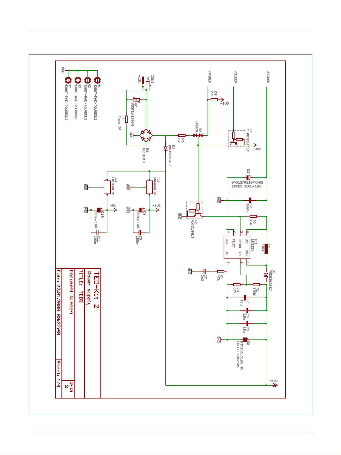
NXP Semiconductors
UM10276_1
TED-Kit 2 User Manual
All information provided in this document is subject to legal disclaimers.
© NXP B.V. 2010. All rights reserved.
User manual
Rev. 1.29 — 20 August 2010
58 of 79
Fig 66. TED-Kit 2 power supply
Page 59

NXP Semiconductors
UM10276_1
TED-Kit 2 User Manual
All information provided in this document is subject to legal disclaimers.
© NXP B.V. 2010. All rights reserved.
User manual
Rev. 1.29 — 20 August 2010
59 of 79
Fig 67. TED-Kit 2 USB/LIN
Page 60

NXP Semiconductors
UM10276_1
TED-Kit 2 User Manual
All information provided in this document is subject to legal disclaimers.
© NXP B.V. 2010. All rights reserved.
User manual
Rev. 1.29 — 20 August 2010
60 of 79
Fig 68. TED-Kit 2 microcontroller
Page 61

NXP Semiconductors
UM10276_1
TED-Kit 2 User Manual
All information provided in this document is subject to legal disclaimers.
© NXP B.V. 2010. All rights reserved.
User manual
Rev. 1.29 — 20 August 2010
61 of 79
Fig 69. TED-Kit 2 extension interface
Page 62

NXP Semiconductors
UM10276_1
TED-Kit 2 User Manual
All information provided in this document is subject to legal disclaimers.
© NXP B.V. 2010. All rights reserved.
User manual
Rev. 1.29 — 20 August 2010
62 of 79
a. Names
d. Values
Fig 70. XBoard/ABIC1 top
a. Names
b. Values
Fig 71. XBoard/ABIC1 bottom
8.2 ABIC1
Page 63

NXP Semiconductors
UM10276_1
TED-Kit 2 User Manual
All information provided in this document is subject to legal disclaimers.
© NXP B.V. 2010. All rights reserved.
User manual
Rev. 1.29 — 20 August 2010
63 of 79
Fig 72. XBoard/ABIC1 layout
Page 64

NXP Semiconductors
UM10276_1
TED-Kit 2 User Manual
All information provided in this document is subject to legal disclaimers.
© NXP B.V. 2010. All rights reserved.
User manual
Rev. 1.29 — 20 August 2010
64 of 79
Fig 73. XBoard/ABIC1 main board interface
Page 65

NXP Semiconductors
UM10276_1
TED-Kit 2 User Manual
All information provided in this document is subject to legal disclaimers.
© NXP B.V. 2010. All rights reserved.
User manual
Rev. 1.29 — 20 August 2010
65 of 79
Fig 74. XBoard/ABIC1 main circuit
Page 66

NXP Semiconductors
UM10276_1
TED-Kit 2 User Manual
All information provided in this document is subject to legal disclaimers.
© NXP B.V. 2010. All rights reserved.
User manual
Rev. 1.29 — 20 August 2010
66 of 79
Fig 75. XBoard/ABIC1 level translation
Page 67

NXP Semiconductors
UM10276_1
TED-Kit 2 User Manual
All information provided in this document is subject to legal disclaimers.
© NXP B.V. 2010. All rights reserved.
User manual
Rev. 1.29 — 20 August 2010
67 of 79
Fig 76. XBoard/ABIC1 power supply
Page 68

NXP Semiconductors
UM10276_1
TED-Kit 2 User Manual
All information provided in this document is subject to legal disclaimers.
© NXP B.V. 2010. All rights reserved.
User manual
Rev. 1.29 — 20 August 2010
68 of 79
Fig 77. XBoard/LoPSTer component/IC names
8.3 LoPSTer
Page 69

NXP Semiconductors
UM10276_1
TED-Kit 2 User Manual
All information provided in this document is subject to legal disclaimers.
© NXP B.V. 2010. All rights reserved.
User manual
Rev. 1.29 — 20 August 2010
69 of 79
Fig 78. XBoard/LoPSTer component/IC values
Fig 79. XBoard/LoPSTer schematic pg 1
Page 70

NXP Semiconductors
UM10276_1
TED-Kit 2 User Manual
All information provided in this document is subject to legal disclaimers.
© NXP B.V. 2010. All rights reserved.
User manual
Rev. 1.29 — 20 August 2010
70 of 79
Fig 80. XBoard/LoPSTer main board interface pg 1
Page 71

NXP Semiconductors
UM10276_1
TED-Kit 2 User Manual
All information provided in this document is subject to legal disclaimers.
© NXP B.V. 2010. All rights reserved.
User manual
Rev. 1.29 — 20 August 2010
71 of 79
Fig 81. XBoard/LoPSTer main board interface pg 2
Page 72

NXP Semiconductors
UM10276_1
TED-Kit 2 User Manual
All information provided in this document is subject to legal disclaimers.
© NXP B.V. 2010. All rights reserved.
User manual
Rev. 1.29 — 20 August 2010
72 of 79
8.4 LF Antenna
The LF-Antenna is provided by VACUUMSCHMELZE GmbH & Co. KG:
VACUUMSCHMELZE GmbH & Co. KG
Dr. Achim Kipper
Phone: +49 (6181) 38-2029 or +49 (6181) 38-0
E-Mail: Achim.Kipper@vacuumschmelze.com
E-Mail: info@vacuumschmelze.com
Web: http://www.vacuumschmelze.com
The antennas are samples and thus, not available as a mass product.
Page 73

NXP Semiconductors
UM10276_1
TED-Kit 2 User Manual
All information provided in this document is subject to legal disclaimers.
© NXP B.V. 2010. All rights reserved.
User manual
Rev. 1.29 — 20 August 2010
73 of 79
Fig 82. LF antenna data sheet page 1
Page 74

NXP Semiconductors
UM10276_1
TED-Kit 2 User Manual
All information provided in this document is subject to legal disclaimers.
© NXP B.V. 2010. All rights reserved.
User manual
Rev. 1.29 — 20 August 2010
74 of 79
Fig 83. LF antenna data sheet page 2
Page 75

Error!
Un-
known
docu-
ment
property
name.
Error! Unknown document property name.
Error! Unknown document property
NXP Semiconductors
UM10276_1
TED-Kit 2 User Manual
All information provided in this document is subject to legal disclaimers.
© NXP B.V. 2010. All rights reserved.
User manual
Rev. 1.29 — 20 August 2010
75 of 79
9. Legal information
9.1 Definitions
Draft — The document is a draft version only. The content is still under
internal review and subject to formal approval, which may result in modifications or additions. NXP Semiconductors does not give any representations
or warranties as to the accuracy or completeness of information included
herein and shall have no liability for the consequences of use of such information.
9.2 Disclaimers
Limited warranty and liability — Information in this document is believed to
be accurate and reliable. However, NXP Semiconductors does not give any
representations or warranties, expressed or implied, as to the accuracy or
completeness of such information and shall have no liability for the consequences of use of such information.
In no event shall NXP Semiconductors be liable for any indirect, incidental,
punitive, special or consequential damages (including - without limitation lost profits, lost savings, business interruption, costs related to the removal
or replacement of any products or rework charges) whether or not such
damages are based on tort (including negligence), warranty, breach of
contract or any other legal theory.
Notwithstanding any damages that customer might incur for any reason
whatsoever, NXP Semiconductors’ aggregate and cumulative liability towards customer for the products described herein shall be limited in accordance with the Terms and conditions of commercial sale of NXP Semiconductors.
Right to make changes — NXP Semiconductors reserves the right to make
changes to information published in this document, including without limitation specifications and product descriptions, at any time and without notice.
This document supersedes and replaces all information supplied prior to the
publication hereof.
Suitability for use — NXP Semiconductors products are not designed,
authorized or warranted to be suitable for use in medical, military, aircraft,
space or life support equipment, nor in applications where failure or malfunction of a NXP Semiconductors product can reasonably be expected to result
in personal injury, death or severe property or environmental damage. NXP
Semiconductors accepts no liability for inclusion and/or use of NXP Semiconductors products in such equipment or applications and therefore such
inclusion and/or use is at the customer’s own risk.
Applications — Applications that are described herein for any of these
products are for illustrative purposes only. NXP Semiconductors makes no
representation or warranty that such applications will be suitable for the
specified use without further testing or modification.
NXP Semiconductors does not accept any liability related to any default,
damage, costs or problem which is based on a weakness or default in the
customer application/use or the application/use of customer’s third party
customer(s) (hereinafter both referred to as “Application”). It is customer’s
sole responsibility to check whether the NXP Semiconductors product is
suitable and fit for the Application planned. Customer has to do all necessary
testing for the Application in order to avoid a default of the Application and
the product. NXP Semiconductors does not accept any liability in this respect.
Export control — This document as well as the item(s) described herein
may be subject to export control regulations. Export might require a prior
authorization from national authorities.
9.3 Trademarks
Notice: All referenced brands, product names, service names and trademarks are property of their respective owners.
HITAG — is a trademark of NXP B.V.
I2C Bus — is a trademark of NXP B.V.
Page 76

NXP Semiconductors
UM10276_1
TED-Kit 2 User Manual
All information provided in this document is subject to legal disclaimers.
© NXP B.V. 2010. All rights reserved.
User manual
Rev. 1.29 — 20 August 2010
76 of 79
Abbreviation
Description
.NET
The Microsoft .NET
Framework is a software
component that is a part of
Microsoft Windows operating systems.
ABIC1
Advanced Base station IC 1
ASCII
American Standard Code
for Information Interchange
EEPROM
Electrically Erasable Programmable Read-Only
Memory
GPIO
General Purpose Input/Output
GUI
Graphical User Interface
I2C, I2C
Inter-Integrated Circuit
IC
Integrated Circuit
IDE
Unique 32-Bit Identifier
used by NXP transponders
ISK
Immobilizer Secret Key
LED
Light-Emitting Diode
LF
Low Frequency
LIN
Local Interconnect Network
LoPSTer
Low Power Single-chip
Transceiver
Abbreviation
Description
PC
Personal Computer
PCB
Printed Circuit Board
PDF
Portable Document Format
PKE
Passive Keyless Entry
RAM
Random Access Memory
RKE
Remote Keyless Entry
RSSI
Receive Signal Strength
Information
SKL
Secret Key Lock
SPI
Serial Peripheral Interface
TED-Kit 2
Transponder Evaluation
and Demonstration-Kit 2
TMCF
Transponder Mode Configuration
UHF
Ultra High Frequency
USB
Universal Serial Bus
WHQL
Windows Hardware Quality
Labs
XBoard
EXtension Board
XSlot
EXtension Slot
10. Abbreviations
Page 77

NXP Semiconductors
UM10276_1
TED-Kit 2 User Manual
All information provided in this document is subject to legal disclaimers.
© NXP B.V. 2010. All rights reserved.
User manual
Rev. 1.29 — 20 August 2010
77 of 79
11. List of figures
Fig 1. System Overview .............................................. 4
Fig 2. TED-Kit 2 main window ..................................... 7
Fig 3. HITAG 2 immobilizer selection .......................... 7
Fig 4. HITAG2 authentication starting ......................... 8
Fig 5. HITAG 2 authentication running ........................ 8
Fig 6. HITAG2 EEPROM content ................................ 9
Fig 7. TED-Kit 2 main window ................................... 10
Fig 8. Hardware view ................................................ 11
Fig 9. Hardware view details ..................................... 11
Fig 10. Applet view...................................................... 12
Fig 11. Applet view deactivated .................................. 12
Fig 12. Immobilizer applet ........................................... 13
Fig 13. ABIC1 configuration window ........................... 14
Fig 14. ABIC1 default configuration ............................ 15
Fig 15. Immobilizer Tx/Rx configuration ...................... 15
Fig 16. Tx/Rx configuration ......................................... 16
Fig 17. Immobilizer default settings............................. 17
Fig 18. Immobilizer starting ......................................... 17
Fig 19. Immobilizer “No Transponder” ........................ 17
Fig 20. Immobilizer IDE ............................................... 18
Fig 21. Immobilizer authenticated ............................... 18
Fig 22. Immobilizer authentication failed ..................... 18
Fig 23. Immobilizer EEPROM ..................................... 19
Fig 24. EEPROM read timings .................................... 19
Fig 25. EEPROM content ............................................ 20
Fig 26. EEPROM TMCF ............................................. 20
Fig 27. EEPROM XMA configuration .......................... 21
Fig 28. EEPROM edit enable ...................................... 21
Fig 29. EEPROM edit controls .................................... 21
Fig 30. Immobilizer stopping ....................................... 22
Fig 31. Immobilizer/RKE applet .................................. 23
Fig 32. Immobilizer/RKE configure ABIC1 .................. 24
Fig 33. Immobilizer/RKE configure LoPSTer .............. 24
Fig 34. LoPSTer configuration window ....................... 25
Fig 35. LoPSTer configuration loading ........................ 25
Fig 36. LoPSTer configuration saving ......................... 26
Fig 37. RKE resynchronization ................................... 27
Fig 38. RKE starting .................................................... 27
Fig 39. RKE polling ..................................................... 28
Fig 40. RKE stopping .................................................. 28
Fig 41. PKE starting .................................................... 29
Fig 42. PKE tag scanning ........................................... 30
Fig 43. PKE cyclic authentication ................................ 30
Fig 44. PKE single authentication ............................... 31
Fig 45. PKE cyclic RSSI .............................................. 32
Fig 46. PKE cyclic RSSI stopped ................................ 32
Fig 47. PKE RSSI ADC ............................................... 33
Fig 48. PKE battery voltage starting ............................ 33
Fig 49. PKE battery voltage load/stop ......................... 34
Fig 50. Figure title here ............................................... 34
Fig 51. TED-Kit 2 about window .................................. 35
Fig 52. Firmware update dialog ................................... 36
Fig 53. TED-Kit 2 unsupported hardware dialog ......... 37
Fig 54. Message view ................................................. 40
Fig 55. Message view details ...................................... 40
Fig 56. Message view context menu ........................... 41
Fig 57. TED-Kit 2 status window ................................. 43
Fig 58. TED-Kit 2 rename dialog ................................. 45
Fig 59. Distance record panel ..................................... 48
Fig 60. Distance record new ....................................... 48
Fig 61. TED-Kit 2 top names ....................................... 55
Fig 62. TED-Kit 2 top values ....................................... 56
Fig 63. TED-Kit 2 bottom names ................................. 56
Fig 64. TED-Kit 2 bottom values ................................. 57
Fig 65. TED-Kit 2 layout .............................................. 57
Fig 66. TED-Kit 2 power supply................................... 58
Fig 67. TED-Kit 2 USB/LIN .......................................... 59
Fig 68. TED-Kit 2 microcontroller ................................ 60
Fig 69. TED-Kit 2 extension interface .......................... 61
Fig 70. XBoard/ABIC1 top ........................................... 62
Fig 71. XBoard/ABIC1 bottom ..................................... 62
Fig 72. XBoard/ABIC1 layout ...................................... 63
Fig 73. XBoard/ABIC1 main board interface ............... 64
Fig 74. XBoard/ABIC1 main circuit .............................. 65
Fig 75. XBoard/ABIC1 level translation ....................... 66
Fig 76. XBoard/ABIC1 power supply ........................... 67
Fig 77. XBoard/LoPSTer component/IC names .......... 68
Fig 78. XBoard/LoPSTer component/IC values .......... 69
Fig 79. XBoard/LoPSTer schematic pg 1 .................... 69
Fig 80. XBoard/LoPSTer main board interface pg 1.... 70
Fig 81. XBoard/LoPSTer main board interface pg 2.... 71
Fig 82. LF antenna data sheet page 1 ........................ 73
Fig 83. LF antenna data sheet page 2 ........................ 74
Page 78

NXP Semiconductors
UM10276_1
TED-Kit 2 User Manual
All information provided in this document is subject to legal disclaimers.
© NXP B.V. 2010. All rights reserved.
User manual
Rev. 1.29 — 20 August 2010
78 of 79
12. List of tables
Table 1. Supported applications and hardware ............... 5
Table 2. TED-Kit 2 status window items ....................... 43
Table 3. EEPROM content ............................................ 51
Page 79

NXP Semiconductors
UM10276_1
TED-Kit 2 User Manual
Please be aware that important notices concerning this document and the product(s)
described herein, have been included in the section 'Legal information'.
© NXP B.V. 2010. All rights reserved.
For more information, please visit: http://www.nxp.com
For sales office addresses, please send an email to: salesaddresses@nxp.com
Date of release: 20 August 2010
Document identifier:
13. Contents
1. Introduction ......................................................... 3
2. System overview ................................................. 3
2.1 Supported applications and hardware ................ 5
3. Setup .................................................................... 5
3.1 System requirements ......................................... 5
3.2 Installing the software ........................................ 5
3.3 Installing the hardware ....................................... 6
3.4 Removing the software ...................................... 6
4. Quick start............................................................ 6
5. Using the GUI software ....................................... 9
5.1 Start the GUI ...................................................... 9
5.2 Exploring the connected TED-Kit 2 boxes ........ 10
5.3 Exploring the available applets ......................... 12
5.4 Running immobilizer applet .............................. 13
5.4.1 Configuring the ABIC1 ..................................... 14
5.4.2 Communication settings ................................... 15
5.4.3 Starting immobilizer .......................................... 16
5.4.4 Exploring transponder memory ........................ 18
5.4.5 Manipulating transponder memory ................... 21
5.4.6 Stopping immobilizer ........................................ 22
5.5 Running RKE applet ......................................... 22
5.5.1 Configuring the ABIC1 ..................................... 23
5.5.2 Configuring the LoPSTer .................................. 24
5.5.3 Configuration persistence ................................ 25
5.5.4 Transponder memory during RKE .................... 26
5.5.5 Resynchronization ............................................ 26
5.5.6 Starting RKE .................................................... 27
5.5.7 Stopping RKE ................................................... 28
5.6 Running PKE applet ......................................... 28
5.6.1 Configuring the ABIC1 ..................................... 29
5.6.2 Configuring the LoPSTer .................................. 29
5.6.3 Transponder memory during PKE .................... 29
5.6.4 Tag scanning .................................................... 29
5.6.5 Cyclic PKE authentication ................................ 30
5.6.6 Single PKE authentication ................................ 31
5.6.7 Cyclic RSSI ...................................................... 31
5.6.8 Cyclic V
5.7 Getting Help ..................................................... 34
5.8 Updating the firmware ...................................... 35
5.9 Using unsupported hardware ........................... 36
6. Reference ........................................................... 37
6.1 Menu bar .......................................................... 37
6.1.1 Board ............................................................... 37
6.1.2 Window ............................................................ 38
6.1.3 Help .................................................................. 38
......................................................... 33
Bat
6.2 Hardware view .................................................. 39
6.3 Applet view ....................................................... 39
6.4 Message view ................................................... 39
6.4.1 Context menu ................................................... 41
6.4.2 Logging............................................................. 42
6.5 TED-Kit 2 status window .................................. 42
6.5.1 Set TED-Kit 2 custom name ............................. 44
6.5.2 Identify TED-Kit 2 ............................................. 45
6.6 XBoard configuration window ........................... 45
6.6.1 ABIC1 configuration window ............................. 46
6.6.2 LoPSTer configuration window ......................... 46
6.7 Immobilizer applet window ............................... 46
6.7.1 HITAG-Pro 2 distance ...................................... 47
6.8 RKE applet window .......................................... 49
6.9 PKE applet window .......................................... 49
6.10 Transponder EEPROM window ........................ 50
7. Troubleshooting ................................................ 52
7.1 Cannot authenticate in immobilizer mode......... 52
7.2 Cannot read data from EEPROM ..................... 53
7.3 Cannot write data into EEPROM ...................... 53
7.4 Use HITAG2-Extended as HITAG2 .................. 54
7.5 No access to HITAG-Pro 2 distance ................. 54
8. PCB and schematics ......................................... 55
8.1 TED-Kit 2 .......................................................... 55
8.2 ABIC1 ............................................................... 62
8.3 LoPSTer ........................................................... 68
8.4 LF Antenna ....................................................... 72
9. Legal information .............................................. 75
9.1 Definitions ......................................................... 75
9.2 Disclaimers ....................................................... 75
9.3 Trademarks ...................................................... 75
10. Abbreviations ..................................................... 76
11. List of figures ..................................................... 77
12. List of tables ...................................................... 78
13. Contents ............................................................. 79
Page 80

Mouser Electronics
Authorized Distributor
Click to View Pricing, Inventory, Delivery & Lifecycle Information:
NXP:
OM6716/434,599
 Loading...