

Page 1

EXTERNAL USE
S32V234-EVB2
QUICK START GUIDE
REV 2. FEBRUARY 2018
Page 2

EXTERNAL USE
1
Table of Contents
• Board Overview
• Power & Reset
• Serial communications
• Boot sources and boot configurations
• Displays
• Camera inputs
Page 3
EXTERNAL USE
2
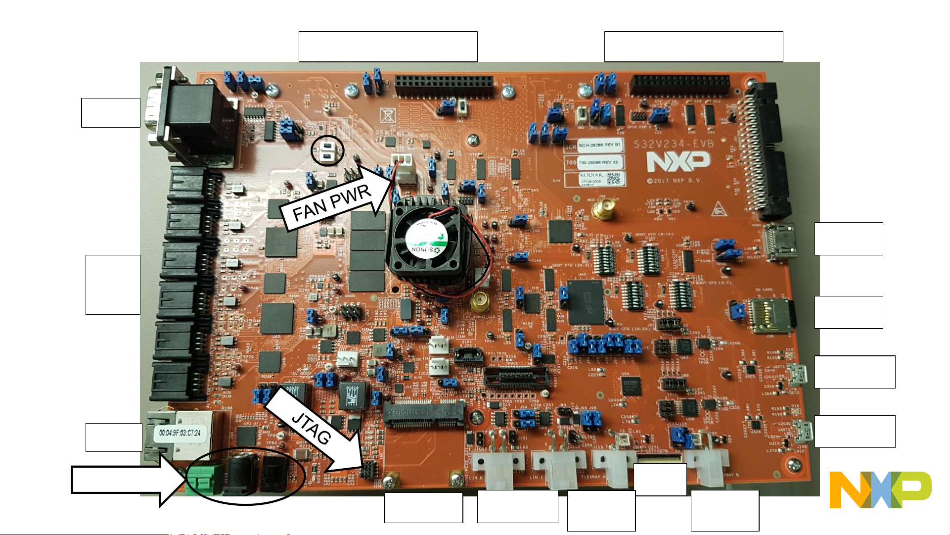
Board Overview
CAN
ETH
Auto
ETH
mPCIE
POWER
HDMI
uSD
UART0
UART1
LIN0/1
LCD
FlexRay
A
FlexRay
B
(On back) MIPI 1
(On back) MIPI 0
Page 4
EXTERNAL USE
3
Power
• EVB2 uses 12V barrel jack power
supply, or wire-ended jack
• DO NOT USE BOTH
SIMULATENOUSLY OR YOU WILL
LIKELY DAMAGE YOUR BOARD
• 12V hot goes to Pin 1 of Barrel jack or
wire-end plug. See rear of board for pin
marking
• Dual position SW (SW9) controls power
flow
• Red TP93 available for measuring 12V
prior to main power SW (SW9)
Page 5

EXTERNAL USE
4
Reset
• EVB2 provides “SOFT RESET” and
“POR RESET” buttons
• Pressing “POR RESET” pulls active low
“EXT_POR” signal on S32V234 chip to
GND
• Pressing “SOFT RESET” pulls active low
“RESET” signal on S32V234 chip to
GND
• Refer to S32V234 Reference Manual for
specifics on levels of reset and device
reset flow
Page 6

EXTERNAL USE
5
Serial Communications
• EVB2 has an FTDI chip to convert UART
signals to USB friendly format, to be
connected to host PC
• UART 0 (with arrow) is default serial output
for Linux BSP boot images.
• Default comms rate is 115200 baud with 8
data bits, 1 stop bit, no parity.
• Use a program such as puTTy, TeraTerm or
Minicom on host PC to communicate with
board
• Lack of serial output on boot can indicate
corrupt (or missing) boot medium, or
improper baud rate. Activity LED is present
near each USB port to indicate serial
communication
Page 7

EXTERNAL USE
6
Boot configurations
• The S32V234 has are three ‘Boot modes’:
o Serial download: Allows external tool to use CAN or UART to download
code into RAM and start execution. Code must be redownloaded on every
reset in this mode. Uses 48kbps baud rate, see S32V234 reference
manual, system boot chapter, for specifics.
o Boot from fuses: Configures device to boot according to the internal
eFuse values programmed at factory, generally not used for evaluation
boards due to lack of custom fuse programming.
o Boot from RCONs: the most common configuration, allows customization
of boot configuration via the 4 8-bit DIP switches on EVB2 (circled in
picture).
• The modes are selected by ‘BOOT_MODE0/1’ signals controlled
by jumpers J40(Boot_Mode[0]) & J42(Boot_Mode[1]), and are
read at reset. By default, the EVB2 is configured to use ‘Boot
from RCONs’ mode. Refer to reference manual ‘System Boot’
chapter for more details on boot modes.
• By default, the board boots from RCON switches, which allow
choosing boot core, and SD card modes for advanced use cases.
(Table to be provided at end of slides.)
• Using Jumpers J48 and J49, the EVB2 can be configured to boot
from SD card, EMMC, or QSPI. Booting from SD card is the
factory default setting.
• Boot from SD: J48=1&2,J49=1&2, SW8 = 0x80
• Boot from EMMC: J48=1&2, J49=2&3, SW8 = 0xC0
• Boot from QSPI: J48=2&3, SW8 = 0x01
Note: Not all configurations of switches are supported by Linux BSP.
Please refer to Linux BSP User Manual for validated modes.
Page 8

EXTERNAL USE
7
Display
• EVB2 has TFT display or
HDMI. Jumper J36
(circled) set to 1&2 for
HDMI (yellow arrow), 2&3
for LVDS (blue arrow)
• NOTE: Power off board
before changing any
jumpers or switches.
Page 9

EXTERNAL USE
8
Camera inputs
• EVB2 two MIPI camera inputs, and two VIU (parallel)
inputs
• NXP and distributors sell MIPI cameras designed for use
with this board
• Additionally can be added and 5V/12V external power
can be provided (see schematics for pinout)
• WARNING: Power off board before changing any
jumpers or switches.
• Configuring optional voltage: For 5V on Cameras 0/1,
set jumpers J7/J5 to 2&3 respectively. For 12V, set to
1&2 respectively.
• Enabling/Disabling optional voltage: To enable opt.
voltage for cameras 0/1, set jumpers J6/J4 to 1&2
respectively. To disable opt. voltage, set J6/J4 to 2&3
respectively.
• NOTE: If you aren’t sure if your camera requires
optional voltage, keep it disabled and refer to
schematics/data sheet for your camera and EVB2.
Page 10

EXTERNAL USE
9
Camera configurations
• By default, jumpers J6 & J4
should be set to 2&3 to keep
optional voltage disabled.
• This configuration is suitable for
most MIPI cameras that do not
require additional voltage supply.
It is also the safest configuration
when using a new camera.
• Two NXP-endorsed MIPI
cameras use this configuration:
the OV10640 module (picture)
and the Sony IMX224 camera.
Page 11

EXTERNAL USE
10
Camera configurations
• Another NXP-endorsed camera module is the
OV10635/10640 with MAXIM 9271 Serializer,
paired with the MAXIM 9286 Deserializer (both
pictured). This camera set requires the optional
12V to be enabled.
• To prepare to use the MAX9271/86 Ser/Des
setup, first ensure power is off and unplugged
from the board. Then, choose between MIPI 0 or
1 and configure only J7 or J5 respectively to 1&2
to select 12V. Then, set jumpers J6 or J4 to 1&2
to enable optional voltage.
• Lastly, confirm that the MAX9286 deserializer
board is configured to use board power by setting
its jumper JU4 to the position shown (For Rev A
deserializer boards). For other revisions, refer to
deserializer schematic to find required
configuration.
• Once all of these are set and cameras are
connected, power can be turned on. Be sure to
power off before removing cameras or
components.
Action
Camera
on MIPI 0
Camera on MIPI
1
Set to 12V
J7=1&2
J5=1&2
Enable voltage
J6=1&2
J4=1&2
Disable voltage
J6=2&3
J4=2&3
Page 12

EXTERNAL USE
11
RCON
Table
See schematics
for RCON to
BOOTCFG
switch mapping.
Note: The Linux
BSP has only
been validated
on certain
configurations.
Please see the
User Manual for
more information
on validated
settings.
Page 13

 Loading...