

Page 1

EXTERNAL USE
REV3
APPLIES FOR: S32K142 EVB (SCH_29701 REV D/C)
QUICK ST ART GUDE
S32K142 EVB
Page 2

EXTERNAL USE
1
Contents:
• Get to Know S32K142 EVB
• Out of the Box Setup
• Introduction to OpenSDA
• Creating a new S32DS project for S32K142:
− Download
− Create a project
− Create a project from SDK example
• S32DS Debug basics
• Create a P&E debug configuration
Page 3
EXTERNAL USE
2
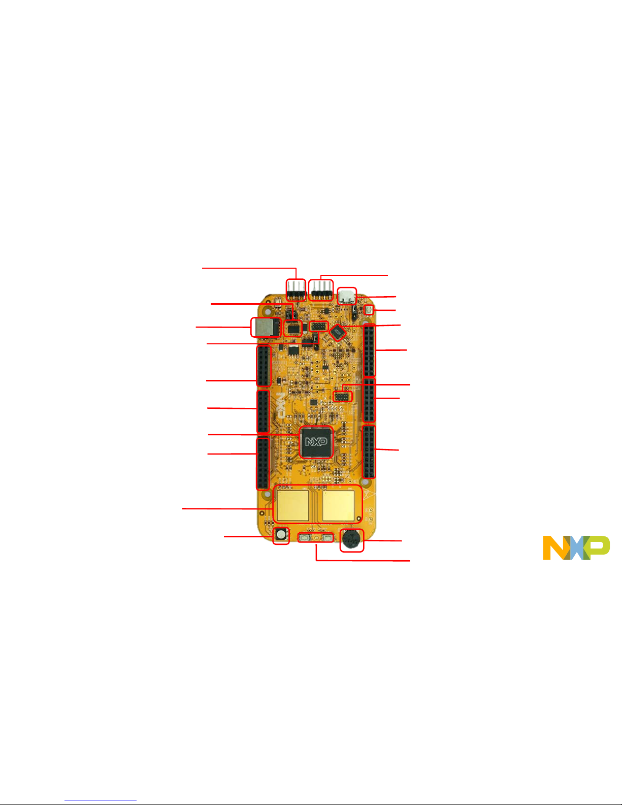
External Power Supply (5-12V)
CAN Communication Bus
RGB LED
S32K142 MCU
LIN Communication Bus
OpenSDA USB
Reset Button
OpenSDA MCU
OpenSDA JTAG
Potentiometer
User Buttons
Get to know S32K142-EVB
J2 Header
J1 Header
J6 Header
J3 Header
J4 Header
J5 Header
SBC UJA1169
Touch electrodes
J14 SWD connector.
Page 4
EXTERNAL USE
3
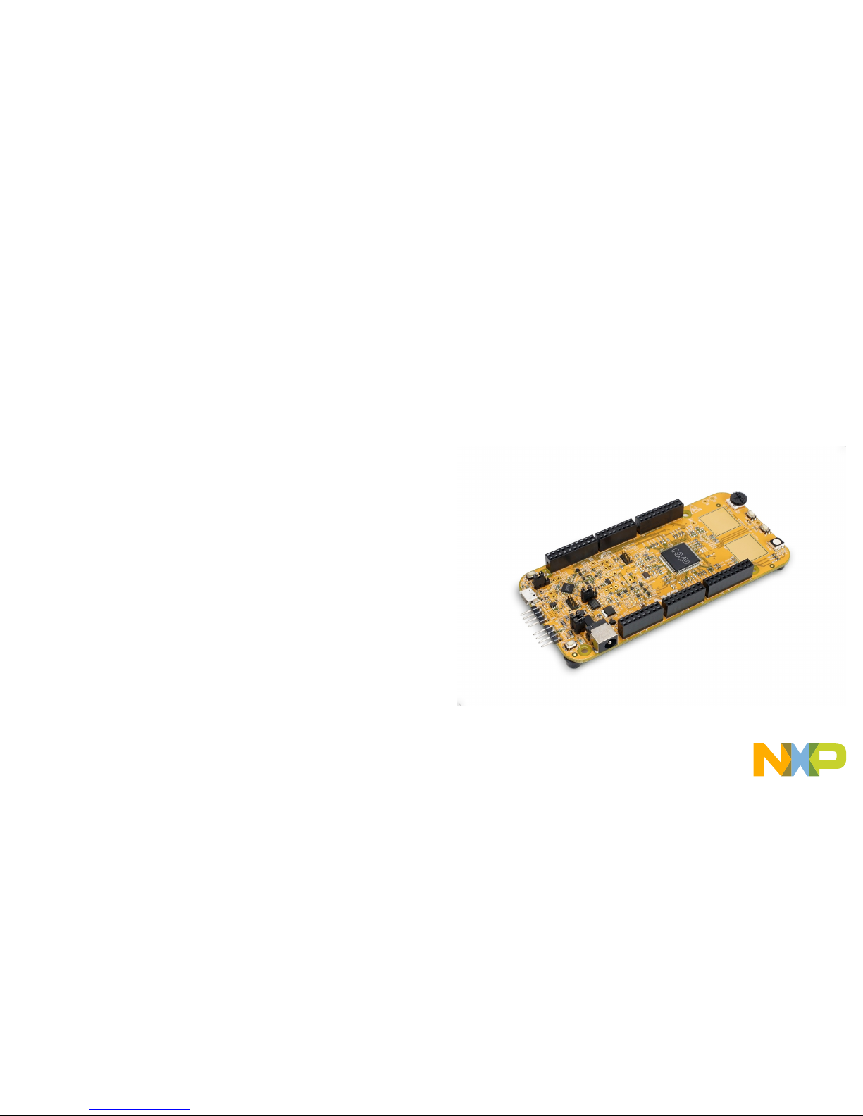
S32K142 EVBFeatures:
• Supports S32K142 and S32K144 100LQFP
• Small form factor size supports up to 6” x 4”
• Arduino™ UNO footprint-compatible with expansion “shield” support
• Integrated open-standard serial and debug adapter (OpenSDA) with
support for several industry-standard debug interfaces
• Easy access to the MCU I/O header pins for prototyping
• On-chip connectivity for CAN, LIN, UART/SCI.
• SBC UJA1169 and LIN phy TJA1027
• Potentiometer for precise voltage and analog measurement
• RGB LED
• Two push-button switches (SW2 and SW3) and two touch electrodes
• Flexible power supply options
• microUSB
• external 12V power supply
Page 5
EXTERNAL USE
4
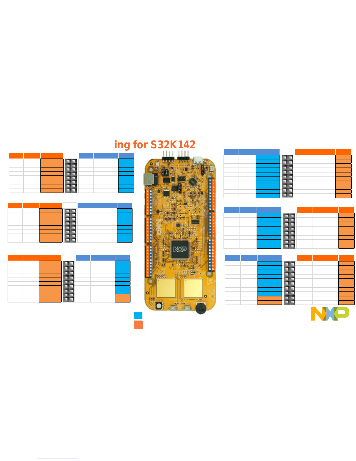
Header/Pinout Mapping for S32K142
Arduino compatible pins
NXP pins
PIN PORT FUNCTION
J3
PIN PORT FUNCTION
J3-02 PTB6* GPIO J3-01 VIN
J3-04 PTB7* GPIO J3-03 IOREF
J3-06 PTE0 GPIO J3-05 PTA5 RESET
J3-08 PTE9 GPIO J3-07 3V3
J3-10 PTC5 GPIO J3-09 5V
J3-12 PTC4 GPIO J3-11 GND
J3-14 PTA 10 GPIO J3-13 GND
J3-16 PTA4 GPIO J3-15 VIN
PIN PORT FUNCTION
J4
PIN PORT FUNCTION
J4-02 PTC7 GPIO J4-01 PTD4 ADC0
J4-04 PTC6 GPIO
J4-03 PTB12 ADC1
J4-06 PTB17 GPIO J4-05 PTB0 ADC2
J4-08 PTB14 GPIO J4-07 PTB1 ADC3
J4-10 PTB15 GPIO J4-09 PTA6/ PTE11/PT A2 ADC4
J4-12 PTB16 GPIO J4-11 PTC0/P TE10/PTA 3 ADC5
J4-14 PTC14 GPIO J4-13 PTE2 ADC6
J4-16 PTC3 GPIO J4-15 PTE6 ADC7
PIN PORT FUNCTION
J5
PIN PO RT FUNCTION
J5-02 PTE16 G PIO J5-01 PTA15/ PTD11 ADC8
J5-04 PTE15 G PIO J5-03 PTA16/ PTD10 ADC9
J5-06 PTE14 G PIO J5-05 PTA1 ADC10
J5-08 PTE13 G PIO J5-07 PTA0 ADC11
J5-10 VDD J5-09 PTA7 ADC 12
J5-12 GND J5-11 PTB13 ADC13
J5-14 PT E1 GPIO J5- 13 PTC1 ADC14
J5-16 PTD 7 GPIO J5-15 PTC2 A DC15
J5-18 PTD 6 GPIO J5-17 NC GPIO
J5-20 P TC15 GPIO J 5-19 NC N/A
PIN
PORT FUNCTION
J2
PIN PO RT FUNCTION
J2- 19 PTE10/P TA3 D15/I2C_S DA J2- 20 NC GPIO
J2- 17 PTE11/P TA2 D14/I2C_C LK J2- 18 NC GPIO
J2- 15 ANALOGU E REF J2- 16 PTA 14 GPIO
J2- 13 GND J2- 14 PTE7 GPIO
J2- 11 PTB2 D13/SPI _SCK J 2-12 P TC13 GPIO
J2- 09 PTB3 D12/SPI _SIN J2-10 P TC12 GPIO
J2- 07 PTB4 D11/SPI _SOUT J2-08 P TE8 GPIO
J2- 05 PTB5 D10/SPI _CS J 2-06 PTD0 GPIO
J2- 03 PTD14 D9/PWM J2-04 PTD 16 GPIO
J2- 01 PTD13 D8/PWM J2-02 PTD 15 GPIO
PIN PORT FUNCTION
J1
PIN PORT FUNCTION
J1- 15 PTC 11/PTE8 D7 J1-16 P TE3 GPIO
J1- 13 PTC 10/PTC3 D6 J1-14 PTD3 GPIO
J1- 11 PTB 11 D5 J1-12 P TD5 GPIO
J1- 09 PTB 10 D4 J1-10 P TD12 GPIO
J1- 07 PTB9 D3 J1-08 P TD11 GPIO
J1- 05 PTB8 D2 J1-06 P TD10 GPIO
J1- 03 PTA3 D1 J1-04 P TA17 GPIO
J1- 01 PTA2 D0 J1-02 P TA11 GPIO
PIN P ORT FUNCTION
J6
PIN P ORT FUNCTION
J6- 19 PTA9 D14 J6-20 PTE4 GPIO
J6- 17 PTA8 D15 J6-18 PTE5 GPIO
J6- 15 PTE12 D16 J6- 16 PTA 12 GPIO
J6- 13 PTD17 D17 J6- 14 PTA 13 GPIO
J6- 11 PTC9 D18 J6-12 GND
J6- 09 PTC8 D19 J6-10 VDD
J6- 07 PTD8 D20 J6-08 PTC 16 GPIO
J6- 05 PTD9 D21 J6-06 PTC 17 GPIO
J6- 03 PTD2 GPIO J6-04 PTD3 G PIO
J6- 01 PTD0 GPIO J6-02 PTD1 G PIO
J2
J1
J6
J3
J4
J5
*0ohm resistor is not connected
Page 6

EXTERNAL USE
5
Jumper Settings
Jumper Configuration Description
J104 1-2
2-3 (Default)
Reset signal to OpenSDA, use to enter into
OpenSDA Bootloader mode
Reset signal direct to the MCU, use to reset
S32K142.
J107 1-2
2-3 (Default)
S32K142 powered by 12V power
source.
S32K142 powered by USB micro
connector.
J10 2-3 (Default)
1-2
MCU voltage 5v
MCU voltage 3.3v
Page 7

EXTERNAL USE
6
HMI mapping
Component S32K142
Red LED PTD15 (FTM0 CH0)
Blue LED PTD0(FTM0 CH2)
Green LED PTD16(FTM0 CH1)
Potentiometer PTC14 (ADC0_SE12)
SW2 PTC12
SW3 PTC13
OpenSDAUART TX PTC7(LPUART1_TX)
OpenSDAUART RX PTC6(LPUART1_RX)
CAN TX PTE5(CAN0_TX)
CAN RX PTE4 (CAN0_RX)
LIN TX PTC3(LPUART0_TX)
LIN RX PTC2 ( LPUAR T0_RX )
SBC_SCK PTB14 (LPSPI1_SCK)
SBC_MISO PTB15(LPSPI1_SIN)
SBC_MOSI PTB16(LPSPI1_SOUT)
SBC_CS PTB17(LPSPI1_PCS3)
Page 8
EXTERNAL USE
7
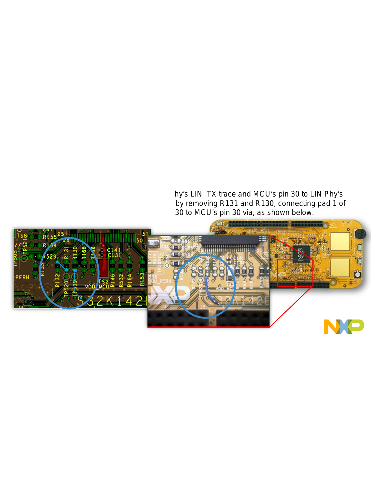
S32K142 EVB RevC. LIN Phy errata.
• Errata: the LIN phy on S32K142EVB is connected to S32K142’s pins 32/31 which don’t support
LPUART.
• Workaround: Connect MCU’s pin 29 to LIN Phy’s LIN_TX trace and MCU’s pin 30 to LIN Phy’s
LIN_RX trace at PCB level. This can be done by removing R131 and R130, connecting pad 1 of
R132(DNP) to pad 2 of R131 and pad 2 of R130 to MCU’s pin 30 via, as shown below.
Note: this errata is already fix on
newest EVB version.
Page 9

EXTERNAL USE
8
S32K142 EVB
OUT OF THE BOX
Page 10
EXTERNAL USE
9
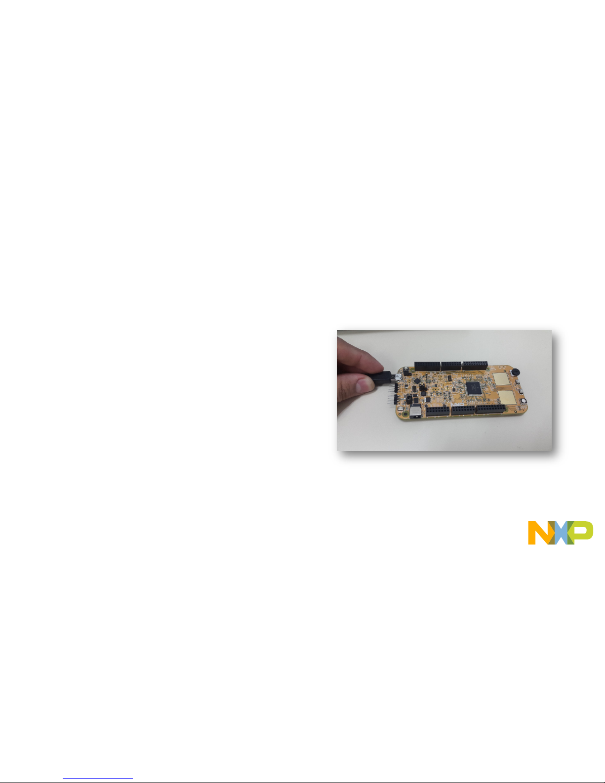
Step 1: Power up the Board – EVB Power Supplies
• The S32K142-EVB evaluation board powers from a USB
or external 12V power supply. By default USB power is
enabled with J107 (check slide 5)
• Connect the USB cable to a PC using supplied USB
cable .
• Connect other end of USB cable (microUSB) to mini-B
port on S32K142-EVB at J7
• Allow the PC to automatically configure the USB drivers if
needed
• Debug is done using OpenSDA through J7
Page 11
EXTERNAL USE
10
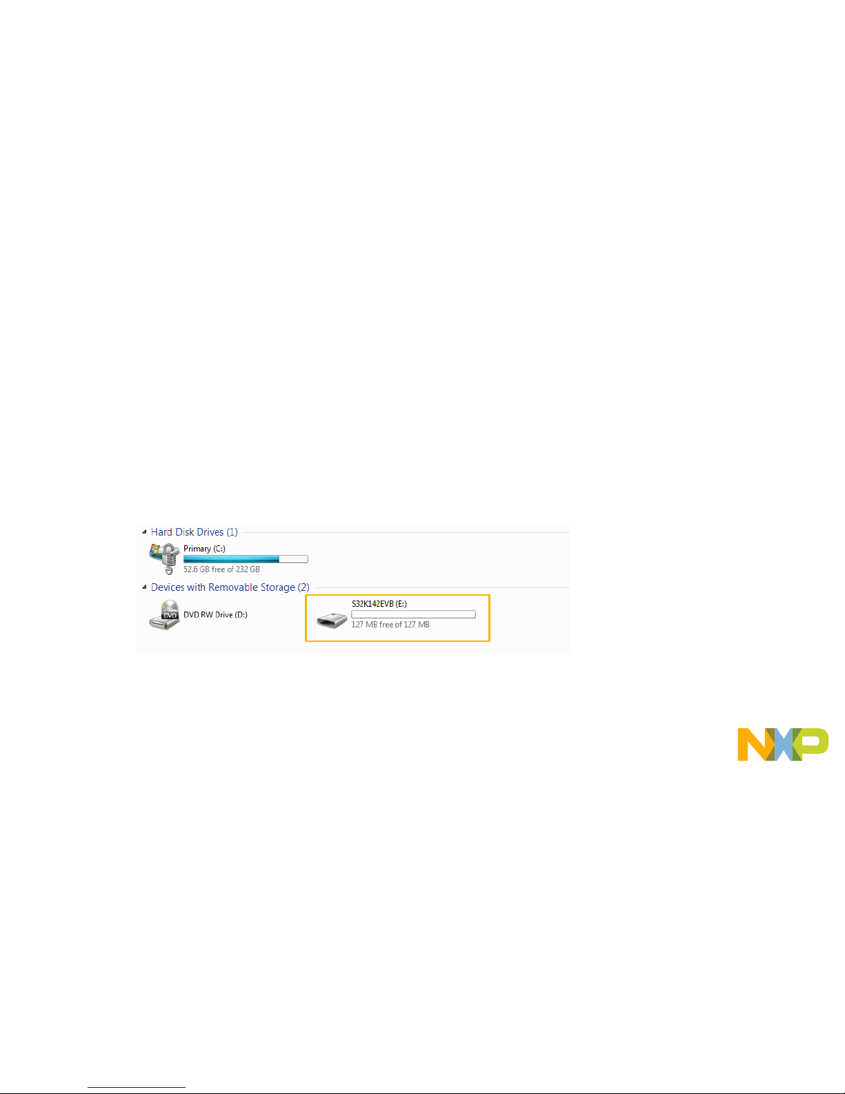
Step 1: Power up the Board – Is it powered on correctly ?
• When powered through USB, LEDs D2 and D3 should light green
• Once the board is recognized, it should appear as a mass stor age
device in your PC with the name EVB-S32K142.
Page 12
EXTERNAL USE
11
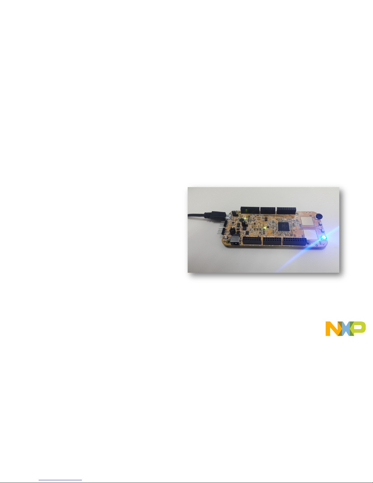
Step 1: Power up the Board – Is it powered on correctly ?
• Board is preloaded with a software, in
which the red, blue and green leds will
toggle at different rates.
Page 13

EXTERNAL USE
12
INTRODUCTION TO
OPENSDA
Page 14

EXTERNAL USE
13
Introduction to OpenSDA: 1 of 2
OpenSDA is an open-standard serial and debug adapter. It bridges serial and debug communications between a USB host and an
embedded target processor. OpenSDA software includes a flash-resident USB mass-storage device (MSD) bootloader and a
collection of OpenSDA Applications. S32K142 EVB comes with the MSD Flash Programmer OpenSDA Application preinstalled.
Follow these instructions to run the OpenSDA Bootloaderand update or change the installed OpenSDA Application.
IMPORTANT NOTE: Follow the “Load an OpenSDA
Application” instructions to update the MSD Flash
Programmer on your S32K142 EVB to the latest
version.
Enter OpenSDA Bootloader Mode
1. Unplug the USB cable if attached
2. Set J104 on position 1-2.
3. Press and hold the Reset button (SW5)
4. Plug in a USB cable (not included) between a
USB host and the OpenSDAUSB connector
(labeled “SDA”)
5. Release the Reset button
A removable dr i ve should now be visible in the host
file system with a volume label of BOOTLOADER.
You are now in OpenSDABootloader mode.
Load an OpenSDA Application
1. While in OpenSDA Bootloadermode, double-click
SDA_INFO.HTML in the BOOTLOADER drive. A web
browser will open the OpenSDAhomepag e contai ning t he
name and version of the installed Application. This
information can also be read as text directly from
SDA_INFO.HTML
2. Locate the OpenSDA Applications
3. Copy & paste or drag & drop the MSD Flash Programmer
Application to the BOOTLOADER drive
4. Unplug the USB cable and plug it in again. The new
OpenSDAApplication should now be running and a
S32K142 EVB drive should be visible in the host file
system
You are now running the latest v er s ion of the M SD Flash
Programmer. Us e this same procedure to load other OpenSDA
Applications.
Page 15

EXTERNAL USE
14
Introduction to OpenSDA: 2 of 2
The MSD Flash Programmer is a composite USB application that provides a virtual serial port and an easy and convenient way to
program applications into the S32K142 MCU. It emulates a FAT file system, appearing as a removable drive in the host file system with
a volume label of EVB-S32K142. Raw binary and Motorola S-record files that are copied to the drive are programmed directly into the
flash of the KEA and executed automatically. The virtual serial port enumerates as a standard serial port device that can be opened with
standard serial terminal applications.
NOTE: Flash programming with the MSD Flash Programmer is
currently only supported on Windows operating systems.
However, the virtual serial port has been successfully tested on
Windows, Linux and Mac operating systems.
Using the MSD Flash Programmer
1. Locate the .srec file of your project , file is under the
Debug folder of the S32DS project.
2. Copy & paste or drag & drop one of the .srec files to
the EVB-S32K142 drive
The new application should now be running on the
S32K142 EVB. Starting wit h v1.03 of the M SD Flash
Programmer, you can progr am repeate dly w ithout the
need to unplug and reattach the USB cable before
reprogramming.
Drag one of the .srec code for the S32K142. the S32K142
EVB board over USB to reprogram the preloaded code
example to another example.
Using the Virtual Serial Port
1. Determine the symbolic name as si g ned to the EVB-S32K142
virtual serial port. In Windows open Device Manager and look
for the COM port named “PEMicro/Freescale –CDC Serial
Port”.
2. Open the serial terminal emulation program of y our choice.
Examples for Windows include
Tera Term, PuTTY, and
HyperTerminal
3. Press and release the Reset button (SW5) at anytime to
restart the example application. Reset ting the embedde d
application will not affect the connection of the virtual serial
port to the terminal program.
4. It is possible to debug and communicate with the serial port
at the same time, no need to stop the debug.
NOTE: Refer to the OpenSDA User’s Guide for a description of a known
Windows issue when disconnecting a virtual serial port while the COM
port is in use.
Page 16

EXTERNAL USE
15
INSTALLING S32DS
Page 17

EXTERNAL USE
16
Download S32DS
Download S32DS from:
S32DS for ARM
Page 18

EXTERNAL USE
17
CREATE A NEW
PROJECT IN S32
DESIGN STUDIO
Page 19

EXTERNAL USE
18
Create New Project: First T ime – Select a Workspace
• Start program: Click on “S32 Design Studio for ARM v2.0” icon
• Select workspace:
− Choose default (see below example) or specify new one
− Suggestion: Uncheck the box “Use this as the default and do not ask again”
− Click OK
Page 20

EXTERNAL USE
19
Create New Project: Top Menu Selection
• File – New –Project
Page 21

EXTERNAL USE
20
Create New Project: S32DS Project
• Project Name:
− Example: FirstProject
• Project Type:
− Select from inside
executable or library folder
• Next
Page 22

EXTERNAL USE
21
Create New Project: S32DS Project
• Select Debugger Support and Library Support
• Click Finish
Page 23

EXTERNAL USE
22
OpenSDA Configuration
• To Debug your project with OpenSDA, it is necessary to select the OpenSDA in the
Debug Configuration.
• Select your project, and click on debug configuration
Page 24

EXTERNAL USE
23
OpenSDA Configuration
• Select the Debug configuration under GDB PEMicro Interface Debugging
• Click on Debugger tab
Page 25

EXTERNAL USE
24
OpenSDA Configuration
• Select OpenSDA as the interface, if your board is plugged should appear in the
Port field.
• Click Apply and debug to finish.
Page 26

EXTERNAL USE
25
CREATE AN EXAMPLE
FROM SDK
Page 27

EXTERNAL USE
26
Creating example from SDK
• The S32 Design Studio IDE already includes the Software Development Kit for
quickly develop applications on S32K1xx devices.
• To create a project using an example go to File – New –Project
Page 28

EXTERNAL USE
27
Creating example from SDK
• Go to the S32K14x EAR SDK v0.8.6 Example Projects section and select the
example that wants to be used.
• In this example the hello_world is selected
Page 29

EXTERNAL USE
28
Creating example from SDK
• A new project would be created in the workspace. Then click on generate code icon and then on
debug, as indicated.
• If run correctly, the LED should start blinking red and green.
Page 30

EXTERNAL USE
29
Creating example from SDK
• The complete documentation of the SDK can be found in:
C:\NXP\S32DS_ARM_v2018.R1\S32DS\S32SDK_S32K14x_EAR_0.8.
6\doc\Start_here.html
• For more information about the use of the SDK go click on the following
link for an SDK tranining (add hyperlink once if is online)
Page 31

EXTERNAL USE
30
DEBUG BASICS
Page 32

EXTERNAL USE
31
Debug Basics: Starting the Debugger
• Debug configuration is only required once. Subsequent starting of debugger does
not require those steps.
• Three options to start debugger:
− If the “Debug Configuration” has not been closed, click on “Debug” button on bottom right
− Select Run – Debug (or hit F11)
Note: This method currently selects the desktop target (project.elf) and gives an error. Do
not use until this is changed.
− Recommended Method: Click on pull down arrow for bug icon and select …_debug.elf
target
Page 33

EXTERNAL USE
32
Debug Basics: Step, Run, Suspend, Resume
• Step Into (F5)
• Step Over (F6)
• Step Return (F7)
• Run
• Suspend
• Resume (F8)
Page 34

EXTERNAL USE
33
Debug Basics: Vi ew & Alter Var iabl es
• View variables in “Variables” tab.
• Click on a value to allow typing in a different value.
Page 35

EXTERNAL USE
34
Debug Basics: Vi ew & Alter Registers
• View CPU regist er s in the “Registers” tab
• Click on a value to allow typing in a different value
• View peripheral registers in the EmbSys Registers tab
Page 36

EXTERNAL USE
35
Debug Basics: Vi ew & Alter Memory
• Add Memory Monitor
• Select Base Address
to Start at : 40000000
• View Memory
Page 37

EXTERNAL USE
36
Debug Basics: Breakpoints
Add Breakpoint: Point and Click
• light blue dot represents debugger breakpoint
Page 38

EXTERNAL USE
37
Debug Basics: Reset & Terminate Debug Session
• Reset program counter
• Terminate Ctl+F2()
Page 39

EXTERNAL USE
38
CREATE A P&E DEBUG
CONFIGURATION
(OPTIONAL)
Page 40

EXTERNAL USE
39
New P&E debug configuration
• Click in debug configurations
Page 41

EXTERNAL USE
40
New P&E debug configuration
• Create a new P&E launch configuration
Click to create a new
P&E launch
Click on the debugger tab.
Page 42

EXTERNAL USE
41
New P&E debug configuration
• Select the device
• Click A pply and debug your applic ation
Select
device
Page 43

EXTERNAL USE
42
USEFUL LINKS
Page 44

EXTERNAL USE
43
Useful Links
• Cookbook application note. This application note contains a
bunch of simple examples of how to use different
peripherals.
• S32K1xx community. Visit this site for request support on
the S32K1xx products, you can also look for threads that
may contain the answer that you are looking for.
Page 45

 Loading...