

Page 1
Quick Start Guide
S12ZVML-MINIKIT
3-phase BLDC and PMSM Development Kit with
NXP S12ZVML128 MCU
Page 2
2
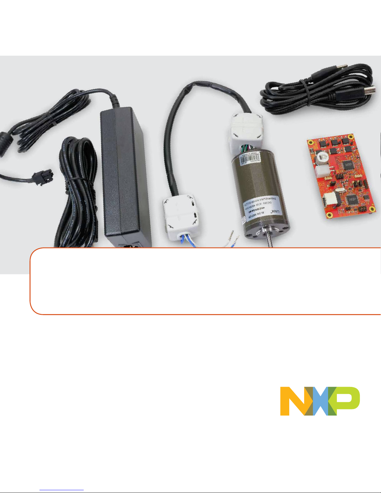
3-PHASE BLDC/PMSM DEVELOPMENT KIT WITH NXP
S12ZVML128 MCU
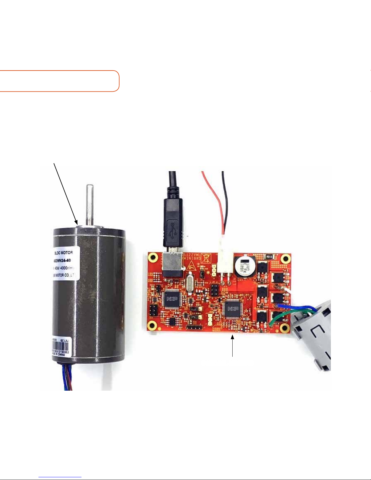
40W PM Motor
Part Number: 45ZWN24-40
S12ZVML-MINIBRD
Page 3
3
GET TO KNOW THE S12ZVML-MINIBRD3-PHASE BLDC/PMSM DEVELOPMENT KIT WITH NXP
www.nxp.com
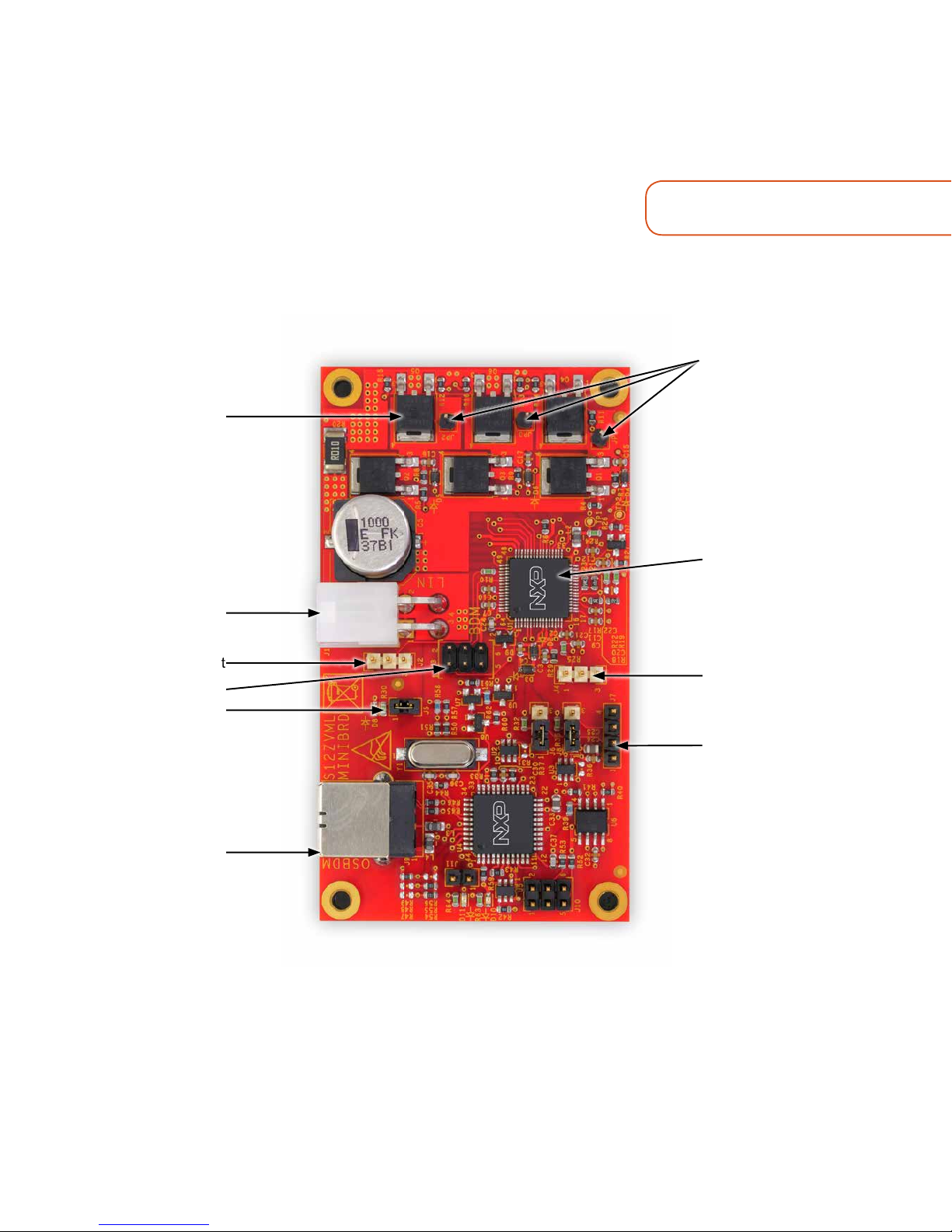
Figure 1: Front side of S12ZVML-MINIBRD
Load Terminals
MC9S12ZVML128
MCU With Load
Current Sense Circuit
Analog /
Digital Input
Serial
Communication
Interface
3-phase
MOSFET Bridge
with Decoupling
Capacitor and Load
Current Sense
Resistor
LIN / Power Supply
Digital Input/
Output
BDM
User LED
OSBDM and USB-
to-SCI Module
Page 4

4
Figure 1: Back side of S12ZVML-MINIBRD
Boost Circuit
Reverse Battery
Protection
GET TO KNOW THE S12ZVML-MINIBRD
Page 5

5
www.nxp.com
S12ZVML-MINIBRD FEATURES
Hardware
• S12ZVML-MINIBRD—
MC9S12ZVML128 with LIN connectivity
support, BDM and OSBDM
downloading and debugging
• Low Cost PM Motor—3-phase PM
motor,24VDC,4000RPM,40W,45Z
WN24-40
• Boost circuitry--allow driving Vgs = 10
V MOSFETs from +3.5 V power supply
• Mini Board size—MC9S12ZVML128
related part size of 5cmx5cm,OSBDM
related part size of 5cmx4cm
• Reverse battery protection
• Load current monitoring
• On-board charge pumps
• USB cable
Software
• Automotive Motor Control Algorithm
– Sensorless control of the
BLDC motor based on Six-step
commutation control technique
allowing torque/speed control with
low CPU load
– High-performance sensorless
field-oriented control of the PMSM
motor with DC-link current sensor
and 3-phase current reconstruction,
field weakening and other
advanced algorithms
• Automotive Math and Motor Control
Library Set — control algorithm built
on blocks of precompiled SW library
• FreeMASTER and MCAT —
Application tuning and variable
tracking
Page 6

6
STEP-BY-STEP INSTRUCTIONS
1
Download
Software
Download installation software and
documentation under “Getting started”
at nxp.com/AutoMCDevKits.
2
Install CodeWarrior
Development Studio IDE
Download and install CodeWrrior
Development Studio IDE version 11.0
available at nxp.com/codewarrior.
3
Install
FreeMASTER
Download and install FreeMASTER
runtime debugging tool available at
nxp.com/FreeMASTER.
4
Download BLDC Motor
Control Software Package
Visit nxp.com/S12ZVML-MINIBRD.
Navigate the “Getting Started” section
and download the latest version of
documentation and software package.
5
Connect the
Motor
Connect the LINIX 45ZWN24-40 3-phase
PM motor to the motor phase terminals
on S12ZVML-MINIBRD board pins
JP1,JP2, JP3.
6
Connect the
Power Supply
Connect the power supply cable with
J1 LIN connector. Keep the DC supply
voltage within the range of -25 V to +25 V,
nominal +12 V.
Page 7

7
STEP-BY-STEP INSTRUCTIONS CONTINUED
www.nxp.com
7
Connect the
USB Cable
Connect S12ZVML-MINIBRD to the PC
using the USB cable. Allow the PC to
automatically configure the USB drivers if
needed.
8
Re-program the MCU using
CodeWrrior IDE
Import the installed application software
project in the CodeWrrior Development
Studio IDE:
• Start CodeWarrior Development Studio
application
• Click File – Import
• Select General – Existing Projects into
Workspace
• Navigate to the installed application
directory:
– for BLDC application: MC_
DevKits\S12ZVMLMINIBRD\sw\
S12ZVMLMINIBRD_BLDC_SW_
CW11 and click OK
– for PMSM application: MC_
DevKits\S12ZVMLMINIBRD\sw\
S12ZVMLMINIBRD_PMSM_SW_
CW11 and click OK
• Click Finish
• Click Run – Debug
Page 8

8
STEP-BY-STEP INSTRUCTIONS CONTINUED
9
FreeMASTER
Setup
• Start the FreeMASTER application
– For BLDC application: Open
FreeMASTER project MC_DevKits\
S12ZVMLMINIBRD\sw\
S12ZVMLMINIBRD_BLDC_SW_
CW11\FreeMASTER_control\
S12ZVMLMINIBRD_BLDC_SW_
CW11.pmp by clicking File – Open
Project
– For PMSM application: Open
FreeMASTER project MC_DevKits\
S12ZVMLMINIBRD\sw\
S12ZVMLMINIBRD_PMSM_SW_
CW11\FreeMASTER_control\
S12ZVMLMINIBRD_PMSM_SW_
CW11.pmp by clicking File – Open
Project
• Click the red STOP button in the
FreeMASTER toolbar or press CTRL+K
to enable the communication.
• Successful communication is signalized
in the status bar at very bottom as
BLDC: “RS232 UART
Communication;COMn;speed = 9600”.
PMSM: “RS232 UART
Communication;COMn;speed =
19200”.
Page 9

9
S12ZVML-MINIBRD JUMPER OPTIONS
www.nxp.com
APPLICATION CONTROL
JUMPER OPTION SETTING DESCRIPTION
J2
Motor run/
stop
1-2 Motor run
2-3 Motor stop
J5
Motor run/
stop
short LED_GREEN Enabled
J6
PS2/
RxD1
1-2 USB OSBDM
2-3
MCU RxD1 connect to J7 SCI port which allows to
connect board external device using the MCU SCI module
J8
PS3/
TxD1
1-2 USB OSBDM
2-3
MCU TxD1 connect to J7 SCI port which allows to
connect board external device using the MCU SCI module
J11
Bootloader
enable
Open Bootloader disabled
1. Click Motor 1 in the Motor Control
Application Tuning tool(MCAT) tool tab
menu to display the motor control page.
2. In case of pending faults, click
the fault button Clear FAULT on
theFreeMASTER MCATControl Page.
3. Start the application by pressing ON/
OFF button on the FreeMASTER
MCAT Control Page .
4. Set required speed by changing
the Speed Required variable value
manually in the.variable watch
window, by clicking speed gauge. For
BLDC application, the speed range
is between 250rpm to 4000rpm. For
PMSM application the speed range
is between -4000rpm to 4000rpm. Do
not exceed 2000rpm for more than 5
minutes.
5. To stop the application, click the ON/
OFF button on the FreeMASTER MCAT
Control page.
Page 10

SUPPORT
Visit www.nxp.com/support for a list
of phone numbers within your region.
WARRANTY
Visit www.nxp.com/warranty for
complete warranty information.
www.nxp.com
NXP, the NXP logo and Kinetis are trademarks of NXP B.V. All other product or service names are the
property of their respective owners. © 2019 NXP B.V.
Document Number: S12ZVMLMKQSG REV 0
Get Started
Download installation
software and documentation
under “Getting Started”
at www.nxp.com/SZVML-MINIBRD.
 Loading...