

Page 1

CONFIDNTIAL AND PROPRIETARY
ULTRA-RELIABLE MICROCONTROLLERS
FOR INDUSTRIALANDAUTOMOTIVE
S12ZVMAEVB
QUICK START GUIDE (QSG)
Page 2
1
CONFIDENTIAL AND PROPRIETARY
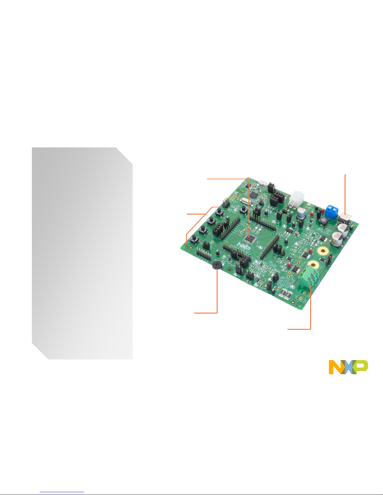
Get to know the S12ZVMAEVB
The S12ZVMA is a
programmable
single-chip solution
for simple loads
needed to be
controlled in the car
remotely via LIN or
PWM command.
Integrated LIN-PHY,
12V-Vreg, and halfbridge gate driver
allow building
extremely compact
solutions for DCmotors, solenoids
or resistive loads
NXP Microcontroller
S12ZVMA
User
Push button [4]
ADC
Potentiometer
Power Supply
Motor Connector
Page 3
2
CONFIDENTIAL AND PROPRIETARY
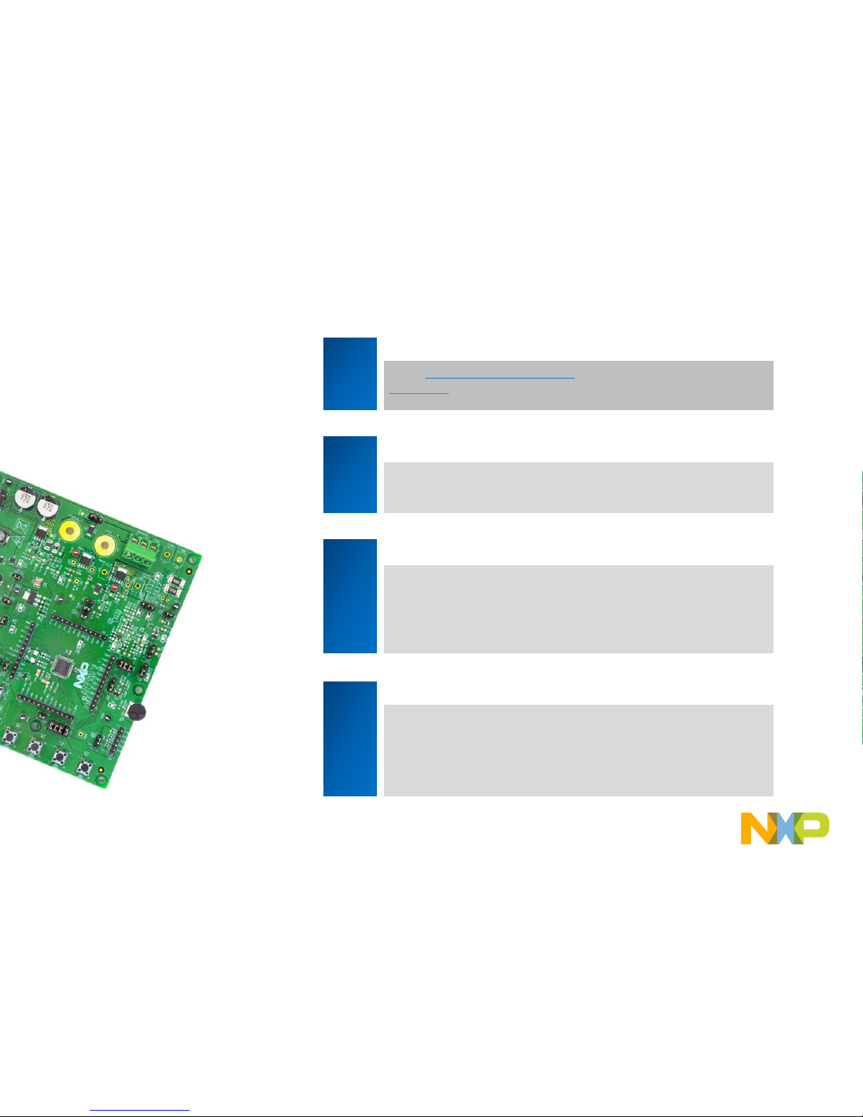
Step-by-Step Installation I nstr uct ions
1
Install Software and Tools
Install
CodeWarrior Development
Studio v11 for S12Z devices. CodeWarrior Dev Tools for MagniV
MCUs
2
Connect the USB Cable
Connect one end of the USB cable to the PC and the other end to
the mini-B connector on the S12ZVMAEVB board. Allow the PC to
automatically configure the USB drivers if needed.
3
Using the Example Project
Load the example code contained in your quick start package to
enable the push buttons and the potentiometer..
4
Learn More About the S12ZVMA
Read the release notes and documentation on the
nxp.com/S12ZVMA.
• The Processor Expert graphical initialization software included in
your CodeWarrior installation will help reduce your time to
market
In this quick start guide, you
will learn how to set up the
S12ZVMAEVB board and
run the default exercise.
Page 4

3
CONFIDENTIAL AND PROPRIETARY
Peripheral List
Peripheral ID MCU PORT Description
Potentiometer R97 PAD3 Potentiometer connectedtoADC channel 3
Temperature sensor KTY82 PAD3 Potentiometer connectedto ADC channel 3
LED – Voltageindicator D9 - VSUP LED Indicator
D10 - HD LED Indicator
D11 - VDDX LED Indicator
LED – User Interface D1 PP0 User LED 1
D2 PP1 User LED 2
D3 PP2 User LED 3
D4 PP3 User LED 4
Switch Panel SW2 PAD6 User switches
SW3 PAD5
SW4 PAD4
SW5 PP4
Reset SW1 - Reset Switch
The table below shows the components available in the EVB as well as the pin number where it’s
connected.
Page 5
4
CONFIDENTIAL AND PROPRIETARY
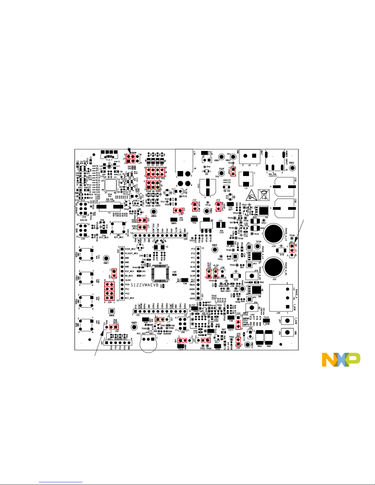
Default Jumper configurati on
Page 6

5
CONFIDENTIAL AND PROPRIETARY
J7 Vsup Enable
Closing This jumper connects Vbat to the rest of the board
J9 Power Supply Voltages – LEEDs indicators
Pin 1-2 Closed Enable Vsup LED indicator
Pin 3-4 Closed Enable HD LED indicator
Pin 5-6 Closed Enable VDDX LED indicator
J15 Master mode enabled
Connects pullup resistors in order for the board to function as LIN
master
J10 Power supply via LIN
Closing this jumper connects Vbat to pin 3 of LIN Connector
J26 VLS OUT enabled
Closing this jumper connects VLS_OUT pin to the rest of the board
Default Jumper configurati on
Page 7

6
CONFIDENTIAL AND PROPRIETARY
J17
VDDX enabled
Closing this jumper connects VDDX to the MCU
J16 VDDX_PERH
Closing this jumper connects VDDX as supplying source for the peripherals
J13 Vol t age supply for the ballast transistor enable
Closing this jumper connects Vsup to the ballast transistor
J12 Vol tage supply for the MCU enable
Closing this jumper connects Vsup to the MCU
J23 Reverse Battery and charge pump enabled
Closing this jumper connects HD signal to the HD_pin of the MCU
J28 High-Side recirculation diode enable
Closing this jumper enables D19 to function as a recirculation diode w hen the m otor is
been drove by the high-side.
Default Jumper configurati on
Page 8

7
CONFIDENTIAL AND PROPRIETARY
J21
Low-side recirculation diode enable
Pin 1-2 Closed Diode is connected to HD
Pin 2-3 Closed Diode is connected to HS
J33 Current measurement selector
Pin 1-2 Closed External operational amplifier is
selected for measure the current
Pin 2-3 Closed Internal operational amplifier is
selected for measure the current
J37 Internal operational amplifier reference v oltage selector
Pin 1-2 Closed 2.5 V reference selected
Pin 2-3 Closed 5 V reference selected
J38 Internal operational amplifier reference v oltage selector
Pin 1-2 Closed 2.5 V reference selected
Pin 2-3 Closed 5 V reference selected
Default Jumper configurati on
Page 9

8
CONFIDENTIAL AND PROPRIETARY
J38
Current measurement operational amplifier output
Pin 1-2 Closed Internal output comparator routed to PAD2
Pin 2-3 Closed External output comparator routed to PAD2
J34 Internal operational amplifier routing
Pin 1-2 Closed Enables 5 V reference to internal operational amplifier
Pin 3-4 Closed AMPP0 routed to PAD0
Pin 5-6 Closed AMPM0 routed to PAD1
J39 2.5 Voltage Enable
Closing this jumper enables the 2.5 V reference for the operational amplifiers.
Default Jumper configurati on
Page 10

9
CONFIDENTIAL AND PROPRIETARY
J22 Switches
Pin 1-2 Closed SW5 routed to PP4
Pin 3-4 Closed SW4 routed to PAD4
Pin 5-6 Closed SW3 routed to PAD5
Pin 7-8 Closed SW2 routed to PAD6
J22 LEDs
Pin 1-2 Closed D1 routed to PP0
Pin 3-4 Closed D2 routed to PP1
Pin 5-6 Closed D3 routed to PP2
Pin 7-8 Closed D4 routed to PP3
Default Jumper configurati on
Page 11

10
CONFIDENTIAL AND PROPRIETARY
J35 Hall Sensor vol tage supply
Pin 1-2 Closed Voltage is supplied to Hall sensor using VDD X
Pin 2-3 Closed Voltage is supplied to Hall sensor using EVDD pin (PP0)
J32 Potenciometer / Temperature Sensor selector
Pin 1-2 Closed Potenciometer is routed to PAD3
Pin 2-3 Closed Temperature sensor is routed to PAD3
J11 Bootloader Enable
Closing this jumper enables the OSBDM to start in bootloader mode.
J22 OSBDM Rx/Tx routing
Pin 1-3 Closed OSBDM Rx routed to PP1
Pin 3-5 Closed OSBDM Rx routed to PE0
Pin 2-4 Closed OSBDM Tx routed to PP0
Pin 7-8 Closed OSBDM Tx routed to PE1
Default Jumper configurati on
Page 12

11
CONFIDENTIAL AND PROPRIETARY
J21 HVI Circuit –Reference V oltage Selector
Pin 1-2 Closed - SW1 is connected to VBA T level. This
provides a HIGH voltage level when switch
SW1 is pressed.
Pin 4-6 Closed - SW1 is connected to GND level. This
provides a LOW v ol t age l evel when switch
SW1 is pressed.
Default Jumper configurati on
Page 13

12
CONFIDENTIAL AND PROPRIETARY
Internal Operational Amplifi er
• The internal amplifier signals of the S12ZVMA EVB are not correctly routed. In
order to use the internal amplifier of the S12ZVMA some jumpers need to be
open and some external cables connected in order to get the amplifier to work:
• Open jumpers: J32, J34 (3-4, 5-6), J38.
• External cables: Connected from J38 pin 1 to PAD3 of the header ring, J34 pin
3 to PAD1 of the header ring, J 34 pin 5 to PAD2 of the header ring.
• The following images show the changes explained above:
Page 14

 Loading...