

Page 1
Freescale Semiconductor
User’s Guide
Document Number: RDAIRBAGPSI5UG
Rev. 2.0, 10/2014
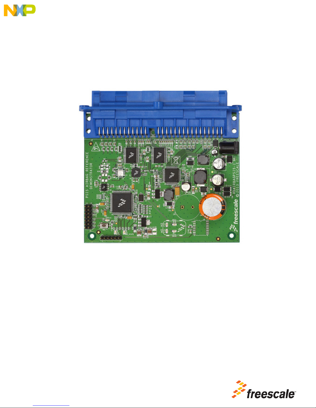
RDAIRBAGPSI5 Airbag Reference Platform
© Freescale Semiconductor, Inc., 2014. All rights reserved.
Figure 1. RDAIRBAGPSI5
Page 2

Table of Contents
1 Important Notice . . . . . . . . . . . . . . . . . . . . . . . . . . . . . . . . . . . . . . . . . . . . . . . . . . . . . . . . . . . . . . . . . . . . . . . . . . . . . . . . . . . . . . . . 3
2 Getting Started . . . . . . . . . . . . . . . . . . . . . . . . . . . . . . . . . . . . . . . . . . . . . . . . . . . . . . . . . . . . . . . . . . . . . . . . . . . . . . . . . . . . . . . . . 4
3 Understanding the System . . . . . . . . . . . . . . . . . . . . . . . . . . . . . . . . . . . . . . . . . . . . . . . . . . . . . . . . . . . . . . . . . . . . . . . . . . . . . . . . 6
4 Getting to know the Hardware. . . . . . . . . . . . . . . . . . . . . . . . . . . . . . . . . . . . . . . . . . . . . . . . . . . . . . . . . . . . . . . . . . . . . . . . . . . . . 10
5 Describing the Device Functions. . . . . . . . . . . . . . . . . . . . . . . . . . . . . . . . . . . . . . . . . . . . . . . . . . . . . . . . . . . . . . . . . . . . . . . . . . . 14
6 Installing the Software and Setting up the Hardware . . . . . . . . . . . . . . . . . . . . . . . . . . . . . . . . . . . . . . . . . . . . . . . . . . . . . . . . . . . 19
7 Schematics . . . . . . . . . . . . . . . . . . . . . . . . . . . . . . . . . . . . . . . . . . . . . . . . . . . . . . . . . . . . . . . . . . . . . . . . . . . . . . . . . . . . . . . . . . . 39
8 Board Layout. . . . . . . . . . . . . . . . . . . . . . . . . . . . . . . . . . . . . . . . . . . . . . . . . . . . . . . . . . . . . . . . . . . . . . . . . . . . . . . . . . . . . . . . . . 45
9 Bill of Material . . . . . . . . . . . . . . . . . . . . . . . . . . . . . . . . . . . . . . . . . . . . . . . . . . . . . . . . . . . . . . . . . . . . . . . . . . . . . . . . . . . . . . . . . 46
10 References . . . . . . . . . . . . . . . . . . . . . . . . . . . . . . . . . . . . . . . . . . . . . . . . . . . . . . . . . . . . . . . . . . . . . . . . . . . . . . . . . . . . . . . . . . 50
11 Revision History . . . . . . . . . . . . . . . . . . . . . . . . . . . . . . . . . . . . . . . . . . . . . . . . . . . . . . . . . . . . . . . . . . . . . . . . . . . . . . . . . . . . . . 51
2 Freescale Semiconductor, Inc.
RDAIRPABPSI5UG , Rev. 2.0
Page 3

1 Important Notice
Freescale provides the enclosed product(s) under the following conditions:
This reference design is intended for use of ENGINEERING DEVELOPMENT OR EVALUATION PURPOSES
ONLY. It is provided as a sample IC pre-soldered to a printed circuit board to make it easier to access inputs,
outputs, and supply terminals. This reference design may be used with any development system or other
source of I/O signals by simply connecting it to the host MCU or computer board via off-the-shelf cables. Final
device in an application will be heavily dependent on proper printed circuit board layout and heat sinking design
as well as attention to supply filtering, transient suppression, and I/O signal quality.
The goods provided may not be complete in terms of required design, marketing, and or manufacturing related
protective considerations, including product safety measures typically found in the end product incorporating
the goods. Due to the open construction of the product, it is the user's responsibility to take any and all
appropriate precautions with regard to electrostatic discharge. In order to minimize risks associated with the
customers applications, adequate design and operating safeguards must be provided by the customer to
minimize inherent or procedural hazards. For any safety concerns, contact Freescale sales and technical
support services.
Should this reference design not meet the specifications indicated in the kit, it may be returned within 30 days
from the date of delivery and will be replaced by a new kit.
Freescale reserves the right to make changes without further notice to any products herein. Freescale makes
no warranty, representation or guarantee regarding the suitability of its products for any particular purpose, nor
does Freescale assume any liability arising out of the application or use of any product or circuit, and
specifically disclaims any and all liability, including without limitation consequential or incidental damages.
“Typical” parameters can and do vary in different applications and actual performance may vary over time. All
operating parameters, including “Typical”, must be validated for each customer application by customer’s
technical experts.
Freescale does not convey any license under its patent rights nor the rights of others. Freescale products are
not designed, intended, or authorized for use as components in systems intended for surgical implant into the
body, or other applications intended to support or sustain life, or for any other application in which the failure
of the Freescale product could create a situation where personal injury or death may occur.
Should the Buyer purchase or use Freescale products for any such unintended or unauthorized application,
the Buyer shall indemnify and hold Freescale and its officers, employees, subsidiaries, affiliates, and
distributors harmless against all claims, costs, damages, and expenses, and reasonable attorney fees arising
out of, directly or indirectly, any claim of personal injury or death associated with such unintended or
unauthorized use, even if such claim alleges that Freescale was negligent regarding the design or manufacture
of the part.Freescale™ and the Freescale logo are trademarks of Freescale Semiconductor, Inc. All other
product or service names are the property of their respective owners.
© Freescale Semiconductor, Inc. 2014
Important Notice
Freescale Semiconductor 3
RDAIRPABPSI5UG , Rev. 2.0
Page 4

Getting Started
2 Getting Started
The RDAIRBAGPSI5 contents include:
• RDAIRBAGPSI5 Airbag Evaluation Platform board
•FTDI Cable
• Warranty card
The RDAIRBAGPSI5-1 contents include:
• RDAIRBAGPSI5-1 Airbag Evaluation Platform board
• PSI5 Satellites modules
• ECU Wiring Harness
•FTDI Cable
• Warranty card
2.1 Jump Start
Freescale’s analog product development boards help to easily evaluate Freescale products. These tools support analog mixed signal and
power solutions that include monolithic ICs using proven high-volume SMARTMOS mixed signal technology, and system-in-package
devices utilizing power, SMARTMOS and MCU dies. Freescale products enable longer battery life, smaller form factor, component count
reduction, ease of design, lower system cost and improved performance in powering state of the art systems.
•Go to www.freescale.com/analogtools
• Locate your kit
• Review your Tool Summary Page
• Look for
• Download documents, software, and other information
Once the files are downloaded, review the user guide in the bundle. The user guide includes setup instructions, BOM and schematics.
Jump start bundles are available on each tool summary page with the most relevant and current information. The information includes
everything needed for design.
4 Freescale Semiconductor, Inc.
RDAIRPABPSI5UG , Rev. 2.0
Page 5

Getting Started
2.2 Required Equipment
Minimum equipment required:
• Power supply (Power Plug or Laboratory Power Supply), with 12 V/2 Amp min current capability
• Oscilloscope (preferably 4-channel) with current probe(s)
• ECU Wiring Harness (included in the RDAIRBAGPSI5-1 kit)
• PSI5 Satellites Sensors (included in the RDAIRBAGPSI5-1 kit)
• Typical loads: 1.2 Ohm/2 Ohm for squibs, switch to ground for DC Sensors, LEDs for GPOs
Recommended equipment for ARP evaluation (GUI):
• FreeMASTER Software installed: http://www.freescale.com/arp
• Airbag Reference Platform FreeMASTER GUI Application: http://www.freescale.com/arp
• USB FTDI cable (Reference: TTL-232R-5V)
All software tools can be downloaded under Software & Tools tab of the RDAIRBAGPSI5 webpage. Registration might be required in order
to get access to the relevant files.
Recommended equipment for software development:
• Freescale CodeWarrior 10.5 or greater for Qorivva MCUs (Eclipse IDE) family installed: http://www.freescale.com/arp
• Airbag System Evaluation Software (source code): http://www.freescale.com/arp
• USB A-B cable
• P&E USB Multilink Debugger for Power Architecture:
http://www.freescale.com/webapp/sps/site/prod_summary.jsp?code=USBMLPPCNEXUS
2.3 System Requirements
• USB-enabled PC with Windows XP or greater
• FTDI Drivers installed for serial communication: http://www.ftdichip.com/Drivers/VCP.htm
Freescale Semiconductor 5
RDAIRPABPSI5UG , Rev. 2.0
Page 6
Understanding the System
3 Understanding the System
The Freescale Airbag Reference Platform (ARP) is an application demonstrator system which provides an airbag Electronic Control Unit
(ECU) implementation example using complete Freescale standard products for the growing automotive safety segment. The GUI
firmware does not constitute a true airbag application but is intended to demonstrate features and capabilities of Freescale's standard
products aimed at the airbag market.
The ARP addresses a mid-range airbag market segment, with up to eight squib drivers (for squibs and seatbelt pre-tensioners) and four
satellite sensor interfaces supporting four or more high g collision sensors positioned around the vehicle. All other vehicle infrastructure
(including seat belt sensors and vehicle communications networks) and ECU functions (including full power supply architecture and a local
mid g X/Y safing sensor) are also supported.
The new ARP hardware is implemented using a standard Freescale Qorivva 32-bit microcontroller (MPC560xP), Analog (MC33789 and
MC33797). In the case of sensors, the families include both local ECU and PSI5 satellite sensors. The ARP implements a system safety
architecture based on the features in the standard products supported by appropriate firmware.
The example ECU is implemented on a single Printed Circuit Board (PCB). Vehicle functions - in principal, satellite sensors, seat belt
switches and warning lamps - can be accessed thanks to the ECU cables.
This User Manual is intended to detail the available hardware functionality and related software drivers (firmware) offered in the Freescale
ARP.
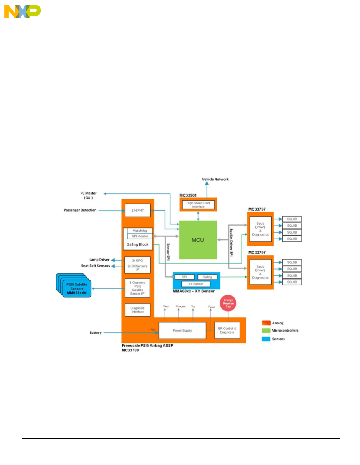
The high level system block diagram here outlines the way the Freescale standard products are used to implement an example airbag
ECU.
6 Freescale Semiconductor, Inc.
Figure 2. RDAIRBAGPSI5 Block Diagram
RDAIRPABPSI5UG , Rev. 2.0
Page 7

3.1 Device Features and Functional Description
This reference design features the following Freescale products:
Table 1. Airbag Reference Platform Device Features
Device Description Features
Understanding the System
MPC560xP
MC33789
MMA68xx
MC33797
MC33901
MMA52xx
MMA51xx
Qorivva 32-bit Microcontroller
Airbag System Basis Chip (PSI5)
ECU Local X/Y Accelerometer
Four Channel Squib Driver
High Speed CAN Physical Layer
High G Collision Satellite Sensor
• Scalable MCU family for safety applications
• e200z0 Power Architecture 32-bit core up to 64 MHz
• Scalable memory, up to 512 KB flash
• Power supply for complete ECU
• Up to four Satellite Sensor interfaces (PSI5)
• Up to nine configurable switch input monitors for simple switch, resistive and
Hall-effect sensor interface
• Safing block and watchdog
• LIN 2.1 physical layer interface
• ±20 g to ±120 g full-scale range, independently specified for each axis
• SPI-compatible serial interface
• 10-bit digital signed or unsigned SPI data output
• Independent programmable arming functions for each axis
• 12 low-pass filter options, ranging from 50 Hz to 1000 Hz
• Four channel high-side and low-side 2.0 A FET switches
• Externally adjustable FET current limiting
• Adjustable current limit range: 0.8 to 2.0 A
• Diagnostics for high-side safing sensor status
• Resistance and voltage diagnostics for squibs
• 8-bit SPI for diagnostics and FET switch activation
• ISO11898-2 and -5 compatible
• Standby mode with remote CAN wake-up on some versions
• Very low current consumption in standby mode, typ. 8 µA
• Excellent EMC performance supports CAN FD up to 2 Mbps
• ±60 g to ±480 g full-scale range
• PSI5 Version 1.3 Compatible (PSI5-P10P-500/3L)
• Selectable 400 Hz, 3 pole, or 4 pole low-pass Filter
• X-axis (MMA52xx) and Z-axis (MMA51xx) available
3.1.1 MPC5602P - Microcontroller
This microcontroller is a member of the highly successful Qorivva MPC560xP family of automotive microcontrollers.
It belongs to an expanding range of automotive-focused products designed to address chassis applications as well as airbag applications.
The advanced and cost-efficient host processor core of this automotive controller family complies with the Power Architecture® embedded
category. It operates at speeds of up to 64 MHz and offers high performance processing optimized for low power consumption. It
capitalizes on the available development infrastructure of current Power Architecture® devices and is supported with software drivers,
operating systems and configuration code to assist with users implementations.
Freescale Semiconductor 7
RDAIRPABPSI5UG , Rev. 2.0
Page 8

Understanding the System
3.1.2 MC33789 - Airbag System Basis Chip
This device implements all vehicle sensor interfaces and the airbag system support functions:
3.1.2.1 Power Supply Block
• A switched-mode power supply DC-DC converter in a boost configuration to generate the high voltage level (33 V), in
which energy is stored in the autarky capacitor, and used to allow continued operation of the airbag system for a defined
time following a collision, which leads to disconnection of the battery
• A switched-mode power supply DC-DC converter in a buck configuration, to efficiently step down the boost supply to a
level suitable for supplying the satellite sensors interfaces (9.0 V) and further regulators, for the local ECU supplies
• A switched capacitor charge pump to double the output of the buck converter, for use in supplying the necessary voltage
for the PSI5 sync pulse generation (18 V)
• A linear regulator to provide the local logic supply (5.0 V) for ECU devices i.e. microcontroller, local sensor, squib driver
3.1.2.2 Safing Block
This block includes a SPI monitor which inputs all inertial sensors (PSI5 satellites and onboard sensors) read by the microcontroller over
the sensor SPI interface, and compares it to pre-defined threshold acceleration values for each local and vehicle collision sensor. Based
on this comparison, where the threshold is exceeded in three consecutive acquisition cycles, the system is armed by enabling the safing
outputs, which in turn enables the squib drivers, so that the application can fire the necessary squibs based on the airbag algorithm results.
3.1.2.3 DC Sensors Interface
A low speed (DC) interface which connects to resistive, simple switch and hall effect sensors which are used to check whether seat belts
are being worn through seat belt switches and seat position through seat track sensors.
3.1.2.4 PSI5 Satellite Sensors Interface
Four Satellite sensors interfaces, which connect to collision sensors distributed around the vehicle. The interfaces are implemented based
on the PSI5 V1.3 specification, and can operate in synchronous modes. It detects current drawn by the satellite and translates the
current-modulated satellite messages into digital data, which the MCU retrieves via the SPI interface.
3.1.2.5 LIN Physical Layer
For connection to vehicle diagnostic interface (K-line) or Occupant Classification System.
3.1.2.6 Lamp Driver
A flexible high or low-side driver which can be configured in hardware which supports PWM driven LED or warning lamp driver.
3.1.2.7 Diagnostics
A number of measures which allow diagnosis of implemented functions on the system basis chip, e.g. all voltage supplies including power
transistor temperature monitors, autarky capacitor ESR, etc.
3.1.2.8 Additional Communication Line
MC33789 is designed to support the Additional Communication Line (ACL) aspect of the ISO-26021 standard, which requires an
independent hardwired signal (ACL) to implement the scrapping feature.
8 Freescale Semiconductor, Inc.
RDAIRPABPSI5UG , Rev. 2.0
Page 9

Understanding the System
3.2 MMA6813KW - ECU Local Sensor
The ECU local sensor acceleration data is used by the airbag application to cross check the acceleration data received from the satellite
collision sensors, to confirm that a collision is really happening, and that airbags need to be deployed.
The local sensor used in the ARP is dual channel, and confirms both frontal and side impacts. In addition, the MMA68xx includes its own
safing block, which will compare the measured acceleration to configurable thresholds and set safing outputs accordingly. This function is
used in the ARP to enable the squib drivers, and therefore be an independent part of the system safing architecture - both the safing blocks
in the system basis chip and in the local sensor must enable the squib drivers before the application is able to fire the appropriate squibs.
3.3 MC33797 - Four Channel Squib Driver
Each channel consists of a high-side and a low-side switch. The ARP uses two MC33797 devices connected in cross-coupled mode, i.e.
high-side switch from one device and low-side switch from the other, connected to each squib or seat belt pre-tensioner. This ensures no
single point of failure in the squib output stage.
The MC33797 implements a comprehensive set of diagnostic features that allows the application to ensure that the squib driver stage is
operating correctly.
3.4 MMA5xxx - High G Satellite Collision Sensor
A single channel acceleration sensor operating in the range of 60 - 480g (depending on G-cell fitted), which includes a PSI5 V1.3 interface
for direct connection to the system basis chip. The device can operate in either asynchronous (point-to-point single sensor connection) or
synchronous (bus mode with multiple sensors connected to each interface) mode. The device can be used either for frontal collisions or
side impacts. For more information about PSI5, please refer to the PSI5 standard specification for airbag systems:
http://psi5.org/
Freescale Semiconductor 9
RDAIRPABPSI5UG , Rev. 2.0
Page 10
Getting to know the Hardware
24-pin connector 32-pin connector
4 Getting to know the Hardware
4.1 Overview
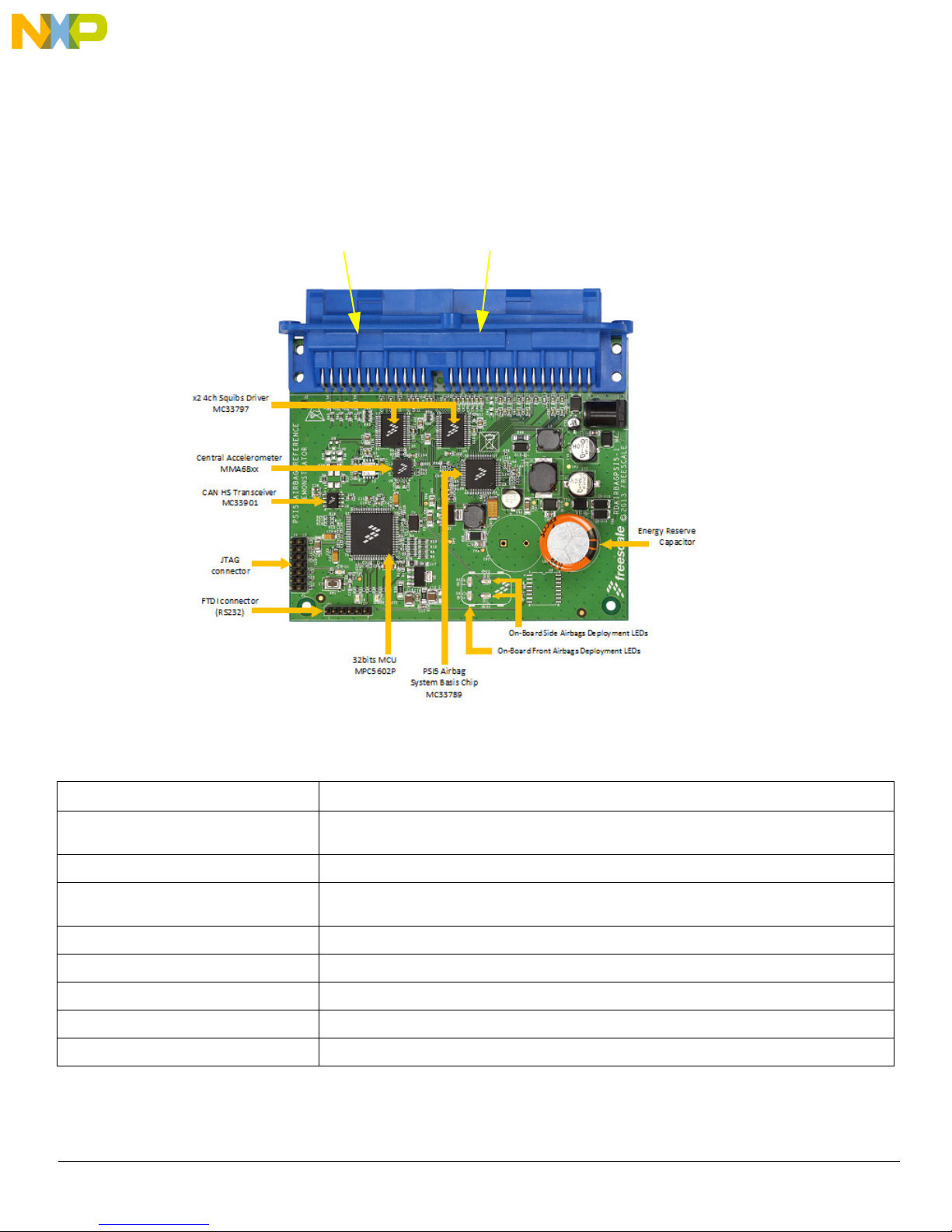
RDAIRBAGPSI5 is an eight loops airbag system ECU. Figure 3 shows all the main components of an airbag ECU hardware. Table 2 lists
all the functions performed by each component.
Figure 3. Board Description
Table 2. Board Description
Name Definition
x2 4ch Squibs Driver MC33797 x2 Four channels Squibs Driver configured in cross-coupled mode to make an eight firing loops airbag
system
Central Accelerometer MMA68xx Central Accelerometer, also called Local Safing Sensor, designed for use in automotive airbag systems
CAN HS Transceiver MC33901 Physical interface between the CAN protocol controller of an MCU and the physical dual wires of the
CAN bus
JTAG Connector P&E USB Multilink Debugger
FTDI Connector (RS232) USB to serial communication connector for GUI application
32-bit MCU MPC5602P Qorivva Power Architecture MCU for Chassis and Safety Application
PSI5 Airbag System Basis Chip MC33789 Airbag System Basis Chip (SBC) with Power Supply and PSI5 Sensor Interface
On-Board Front Airbags Deployment LEDs 2x LEDs used to indicate a front impact Deployment event: Front Driver and/or Front Passenger
10 Freescale Semiconductor, Inc.
RDAIRPABPSI5UG , Rev. 2.0
Page 11
Getting to know the Hardware
REDD2,3,4,5
OrangeD6
GreenD7
YellowD1
Table 2. Board Description (continued)
Name Definition
On-Board Side Airbags Deployment LEDs 2x LEDs used to indicate a side impact Deployment event: Rear Right and/or Rear Left
Energy Reserve Capacitor Autarky Capacitor used as Energy Reserve in case of Battery disconnection
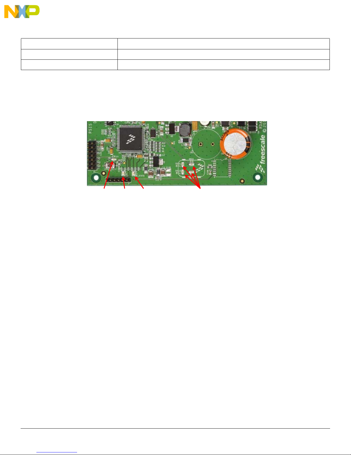
4.2 LED Display
This section describes the LEDs on the lower portion of the RDAIRBAGPSI5 board.
Figure 4. LED Locations
The following LEDs are provided as visual output devices for the RDAIRBAGPSI5 board:
1. LED D1 indicates when a System Reset occurred (LED color: Yellow).
2. LED D2 first indicates MC33789 is correctly initialized only during INIT phase. Then, it is used to display Front
Passenger deployment during GUI Application mode (LED color: Red).
3. LED D3 first indicates MMA68xx is correctly initialized only during INIT phase. Then, it is used to display Rear Right
Side deployment during GUI Application mode (LED color: Red).
4. LED D4 first indicates MC33797 are correctly initialized only during INIT phase. Then, it is used to display Front Driver
deployment during GUI Application mode (LED color: Red).
5. LED D5 first indicates MCU is correctly initialized only during INIT phase. Then, it is used to display Rear Left Side
deployment during GUI Application mode (LED color: Red).
6. LED D6 indicates when a FCU fault is detected by MCU (LED color: Orange).
Note: If no FCU faults are detected, LED is turned ON.
7. LED D7 indicates MCU Software is running (LED color: Green).
Freescale Semiconductor 11
RDAIRPABPSI5UG , Rev. 2.0
Page 12
Getting to know the Hardware
Pin 2
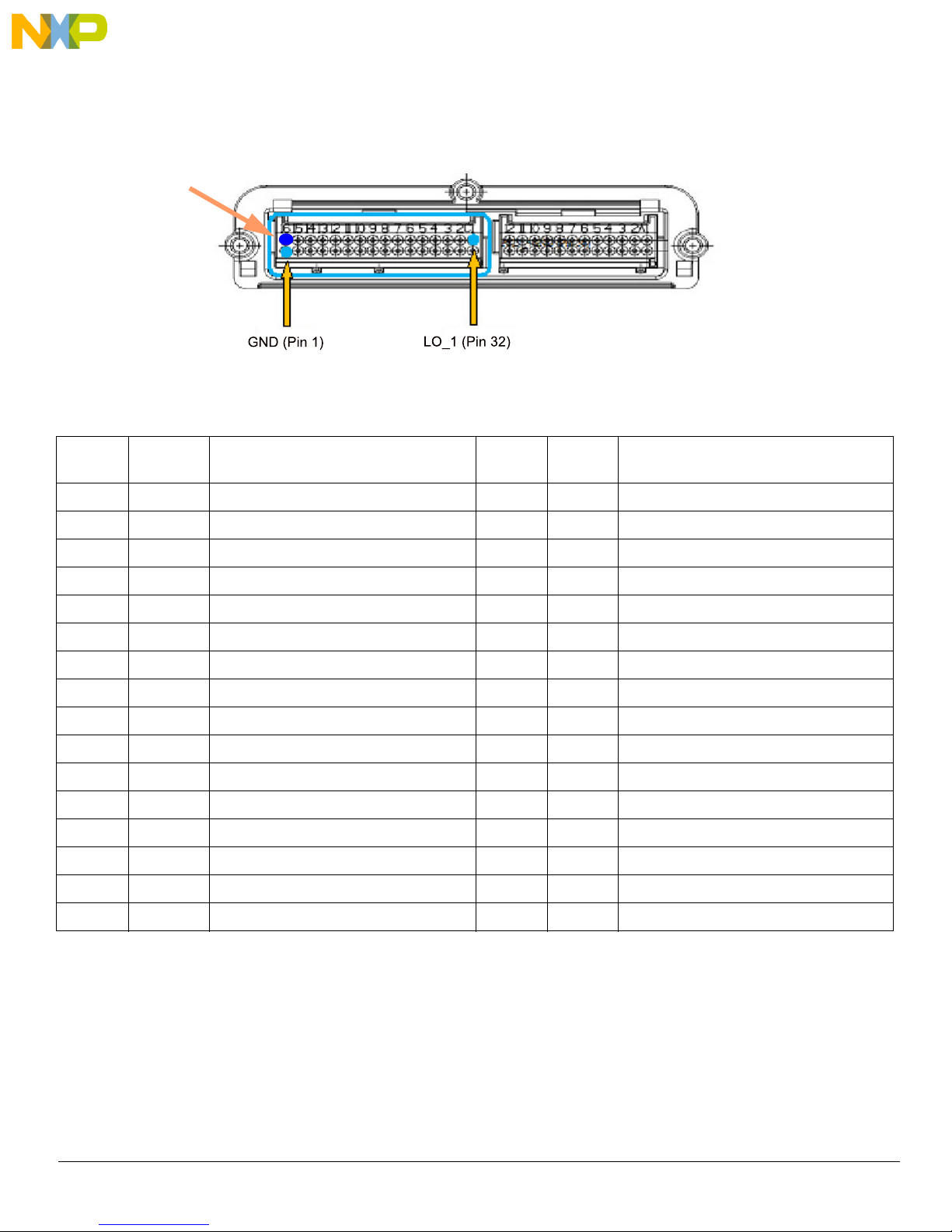
4.3 Connectors
This section discusses the ARP 32-pin and 24-pin positions and their descriptions.
Figure 5. J1 32-pin Connector Location
Table 3: 32-pin Connector Pin List
Position
1 GND Ground Signal 17 IN6 Port 6 of input monitor for DC sensor
2 VBAT Battery Voltage 18 IN5 Port 5 of input monitor for DC sensor
3 GND Ground Signal 19 IN4 Port 4 of input monitor for DC sensor
4 VBAT Battery Voltage 20 IN3 Port 3 of input monitor for DC sensor
5 NC Not connected 21 IN2 Port 2 of input monitor for DC sensor
6 NC Not connected 22 IN1 Port 1 of input monitor for DC sensor
7 OUT2_S Source pin of configurable output FET 2 23 CANH CAN Bus High Signal
8 OUT2_D Drain pin of configurable output FET 2 24 CANL CAN Bus Low Signal
9 OUT1_D Drain pin of configurable output FET 1 25 HI_4 Source of the Squib Driver High-side switch 4
10 OUT1_S Source pin of configurable output FET 1 26 LO_4 Drain of the Squib Driver Low-side switch 4
11 LIN_GND LIN Ground 27 HI_3 Source of the Squib Driver High-side switch 3
12 LIN LIN Signal 28 LO_3 Drain of the Squib Driver Low-side switch 3
13 NC Not connected 29 HI_2 Source of the Squib Driver High-side switch 2
14 IN9 Port 9 of input monitor for DC sensor 30 LO_2 Drain of the Squib Driver Low-side switch 2
15 IN8 Port 8 of input monitor for DC sensor 31 HI_1 Source of the Squib Driver High-side switch 1
Signal
name
Description Position
Signal
name
Description
16 IN7 Port 7 of input monitor for DC sensor 32 LO_1 Drain of the Squib Driver Low-side switch 1
12 Freescale Semiconductor, Inc.
RDAIRPABPSI5UG , Rev. 2.0
Page 13
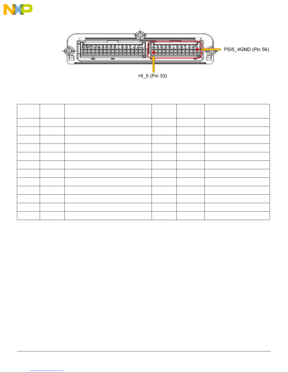
Table 4: 24-pin Connector List
Getting to know the Hardware
Figure 6. J2 24-pin Connector Location
Position
33 HI_5 Source of the Squib Driver High-side switch 5 45 NC Not Connected
34 LO_5 Drain of the Squib Driver Low-side switch 5 46 NC Not Connected
35 HI_6 Source of the Squib Driver High-side switch 6 47 NC Not Connected
36 LO_6 Drain of the Squib Driver Low-side switch 6 48 NC Not Connected
37 HI_7 Source of the Squib Driver High-side switch 7 49 PSI5_1OUT PSI5 Channel1 Signal line
38 LO_7 Drain of the Squib Driver Low-side switch 7 50 PSI5_1GND PSI5 Channel1 Ground line
39 HI_8 Source of the Squib Driver High-side switch 8 51 PSI5_2OUT PSI5 Signal Channel2 line
40 LO_8 Drain of the Squib Driver Low-side switch 8 52 PSI5_2GND PSI5 Channel2 Ground line
41 GND Ground signal 53 PSI5_3OUT PSI5 Channel3 Signal line
42 GND Ground signal 54 PSI5_3GND PSI5 Channel3 Ground line
43 NC Not Connected 55 PSI5_4OUT PSI5 Channel4 Signal line
44 NC Not Connected 56 PSI5_4GND PSI5 Channel4 Ground line
Signal
name
Description Position Signal name Description
Freescale Semiconductor 13
RDAIRPABPSI5UG , Rev. 2.0
Page 14

Describing the Device Functions
5 Describing the Device Functions
The RDAIRBAGPSI5UG Airbag Reference Platform is aimed to cover all major functions of a true airbag system application.
The following section describes individual functions and available view using the GUI:
5.1 MC33789 - Airbag System Basis Chip
5.1.1 Power Supply - Boost Converter and Energy Reserve
Table 5. Power Supply - Boost Converter and Energy Reserve
Define Function Config Register Diagnosis Comment
MC33789 Energy Reserve Supply PS_CONTROL AI_CONTROL
Default setting for the boost converter is ON and will start up when VBATT exceeds a predefined limit. Initially, the boost converter will
charge a small capacitor. Default setting for the energy reserve is OFF to prevent excessive inrush current at key on. The firmware must
turn the energy reserve on through the PS_CONTROL register once VBOOST is stable. Firmware can monitor VBOOST through the
analog output pin selected through AI_CONTROL register. After the energy reserve is turned on, the large energy reserve capacitor (min
2200 µF) will be charged.
5.1.2 Power Supply - Energy Reserve Capacitor ESR Diagnostic
Table 6. Power Supply - Energy Reserve Capacitor ESR Diagnostic
Define Function Config Register Diagnosis Comment
MC33789 Energy Reserve
Capacitor Diagnostic
During ESR diagnostic, the energy reserve capacitor is slightly discharged and the firmware can calculate, based on the discharge rate,
the value of the capacitor's equivalent series resistance (ESR) - this is a measure of the condition of the capacitor.
ESR_DIAG ESR_DIAG
5.1.3 Power Supply - Buck Converter
Table 7. Power Supply - Buck Converter
Define Function Config Register Diagnosis Comment
MC33789 Vcc5, DC Sensor and
Satellite Sensor Supply
Buck converter is internally enabled when the VBOOST voltage is above the under-voltage lockout threshold. The firmware cannot disable
the Buck converter in the RDAIRBAGPSI5 application.
PS_CONTROL AI_CONTROL
14 Freescale Semiconductor, Inc.
RDAIRPABPSI5UG , Rev. 2.0
Page 15

5.1.4 Power Supply - SYNC Pulse Supply
Table 8. Power Supply – SYNC Pulse Supply
Define Function Config Register Diagnosis Comment
Describing the Device Functions
MC33789 Satellite Sensor SYNC
Pulse Supply
Default setting for the SYNC supply is OFF. Firmware needs to turn the SYNC supply on through PS_CONTROL register only if the satellite
sensors are operating in synchronous mode. Firmware can monitor VSYNC voltage through the analog output pin selected through the
AI_CONTROL register.
PS_CONTROL AI_CONTROL
5.1.5 Power Supply - ECU Logic Supply
Table 9. Power Supply - ECU Logic Supply
Define Function Config Register Diagnosis Comment
MC33789 Linear Regulator – –
The internal ECU logic supply is always on and firmware has no configuration to perform.
5.1.6 Safing Block - Sensor Data Thresholds
Table 10. Safing Block - Sensor Data Thresholds
Define Function Config Register Diagnosis Comment
MC33789 Threshold T_UNLOCK,
SAFE_TH_n
–
In order to be able to change the sensor data threshold value or values at which the ARM/DISARM pins are set to their active states (i.e.
the system is armed when a sensor value exceeds the defined threshold), a secure firmware sequence must be carried out to unlock the
threshold register using T_UNLOCK. Once that is done, the threshold can be changed by firmware through the SAFE_TH_n register.
Notes: There is no special firmware required to input sensor data into the safing block. The SPI protocol on the sensor SPI interface is
the same to both the local sensor and the satellite sensor interfaces on the system basis chip, and whenever the microcontroller reads a
sensor value, the response from the sensor or system basis chip is recognized as being sensor data, and is automatically read into the
safing block. The only requirement the application has to meet is that the sensor data is read in the correct sequence, starting with the
local sensor X-axis data followed by the Y-axis, and then the satellite sensor interfaces on the system basis chip.
5.1.7 Safing Block - Diagnostics
Table 11. Safing Block - Diagnostics
Define Function Config Register Diagnosis Comment
MC33789 Linear Regulator – SAFE_CTL
The firmware has the capability to change the mode in which the safing block is operating, so that diagnosis of the ARM/DISARM pins can
be diagnosed or the scrapping mode (i.e. the system is armed when no sensor data exceeds any threshold, used to fire all squibs when
a vehicle is being scrapped) can be entered. Either of these changes is only possible at startup prior to the safing block entering normal
operation.
Freescale Semiconductor 15
RDAIRPABPSI5UG , Rev. 2.0
Page 16

Describing the Device Functions
5.1.8 DC Sensors
Table 12. DC Sensors
Define Function Config Register Diagnosis Comment
MC33789 Seat belt/Seat track
sensor interface
The firmware must select which DC sensor is active and which supply voltage is used on that sensor through the DCS_CONTROL register.
The firmware must also select the correct sensor to be read through the analog output pin using the AI_CONTROL register. Note that both
registers can be returned to their default state by a correct write to the DIAG_CLR register.
DCS_CONTROL,
AI_CONTROL
–
5.1.9 PSI5 Satellite Sensor Interface
Table 13. PSI5 Satellite Sensor Interface
Define Function Config Register Diagnosis Comment
MC33789 Satellite Sensor LINE_MODE,
LINE_ENABLE
The firmware must select the correct mode of operation of the satellite sensor interface and enable each interface individually. The
interfaces should be enabled one at a time to reduce current inrush.
When the interface is enabled, the satellite sensor will automatically send its initialization data, and the firmware must handle this data to
ensure the sensor is operating correctly.
5.1.9.1 LIN Physical Layer
Table 14. LIN Physical Layer
–
Define Function Config Register Diagnosis Comment
MC33789 LIN physical layer LIN_CONFIG –
The firmware has the potential to change the configuration of the LIN physical layer, but the default setting is the most common
configuration.
A special mode exists which allows the Manchester encoded data from a satellite sensor to be monitored on the LIN RXD output pin, for
example in case MCU has a PSI5 peripheral module embedded.
5.1.9.2 Lamp Driver
Table 15. Lamp Driver
Define Function Config Register Diagnosis Comment
MC33789 Lamp driver GPOn_CTL GPOn_CTL
The firmware must configure whether the driver is a high or low-side switch, and the PWM output duty cycle. In the response to the
command, the firmware can check that high or low thresholds on the pins have been exceeded, and whether an over-temperature
shutdown has occurred.
As part of the application, the warning lamp should be turned on at key on, kept illuminated until the startup diagnostic procedure has
completed, and the system is ready to start operating.
16 Freescale Semiconductor, Inc.
RDAIRPABPSI5UG , Rev. 2.0
Page 17

Describing the Device Functions
5.1.9.3 Diagnostics
Table 16. Diagnostics
Define Function Config Register Diagnosis Comment
MC33789 Diagnostics – STATUS, AI_CONTROL
The firmware can monitor the operation of the main ASSP through the STATUS and AI_CONTROL registers.
5.2 MMA6813KW - Local ECU Acceleration Sensor
The local ECU acceleration sensor is a dual channel device which also includes a safing block. At start up, the configuration, offset
cancellation, and self test of the device, occur before the configuration is complete ('ENDINIT' set) and the device goes into normal
operation.
5.2.1 Configuration - General
Table 17. Configuration - General
Define Function Config Register Diagnosis Comment
MMA6813KW Configuration DEVCFG –
The general configuration sets up the data format, whether offset monitoring is enabled, and the functionality of the ARM_X and ARM_Y
output pins. When configuration is complete, the ENDINIT bit is set and this locks out access to the configuration registers.
5.2.2 Configuration - Axis Operation
Table 18. Configuration - Axis Operation
Define Function Config Register Diagnosis Comment
MMA6813KW Configuration DEVCFG_X,
DEVCFG_Y
The axis operation configuration triggers self-test and selects one of the low pass filter options for each axis.
–
5.2.3 Configuration - Arming Operation
Table 19. Configuration - Arming Operation
Define Function Config Register Diagnosis Comment
MMA6813KW Configuration ARMCFG_X,
ARMCFG_Y
–
The arming operation configuration defines the arming pulse stretch period and the arming window, which has different meanings,
depending on which arming mode is configured.
Freescale Semiconductor 17
RDAIRPABPSI5UG , Rev. 2.0
Page 18

Describing the Device Functions
5.2.4 Configuration - Arming Threshold
Table 20. Configuration - Arming Threshold
Define Function Config Register Diagnosis Comment
MMA6813KW Configuration ARMT_XP, ARMT_XN
ARMT_YP, ARMT_YN
For each axis, both the positive and negative threshold can be set above which and when the arming window requirements are met, the
arm outputs will be set to active as defined in the arming operations register.
In the startup phase, the threshold can be set to such a level that when the self test deflection is triggered, the arming outputs will become
active. This can be used as part of the self-test at startup. After completion of the self test, thresholds should be set back to the correct
application values, and before the configuration is complete, by setting the 'ENDINIT' bit, after which no further configuration changes can
be made.
The complete startup and self-test procedure is described in the ARP specification (Airbag Reference Platform).
Note that after the configuration is complete and the 'ENDINIT' bit is set, a CRC check of the configuration is carried out in the background,
which will lead to an error in the status register if a configuration bit flips.
–
5.2.5 Status
Table 21. Status
Define Function Config Register Diagnosis Comment
MMA6813KW Status – DEVSTAT
Internal errors are flagged in the DEVSTAT register.
5.3 MC33797 - Four Channel Squib Driver (FCS)
The ARP uses two Four Channel Squib Drivers (FCS) configured in cross-coupled mode to safely implement eight squib drivers.
The four channel squib driver is addressed using an 8-bit SPI interface over which commands and data are sent.
The only configuration possible is the time the device remains enabled after the fire enable (FEN1, FEN2) pins have been activated. This
is equivalent to the arming pulse stretch time applied to the safing output on both the system basis chip and the local ECU sensor. Two
commands are required to change this time - first is an unlock command and second is the programmed time between 0 and 255
Default is 0
Firing the squibs also requires two commands - the first arms one of the banks of drivers, the second turns on the required switches. More
than one switch can be turned on by a single command.
The majority of the commands relate to diagnostics of the four channel squib driver and the connected squibs. A full list of diagnostic
commands is available in the ARP specification (Airbag Reference Platform).
ms.
ms.
5.4 MMA5xxx High G Satellite Collision PSI5 Sensor
Configuration of the device is done off line prior to assembly in the system.
As soon as the device is switched on, it will begin an internal configuration and self test, and also sends initialization data, which is received
in the system basis chip and checked by the application. Once the device has completed sending the initialization data, which concludes
with an OK or NOK message, it enters normal operation and starts sending sensor data, either autonomously if in asynchronous mode,
or in response to SYNC pulses on the satellite sensor interface if in synchronous mode.
18 Freescale Semiconductor, Inc.
RDAIRPABPSI5UG , Rev. 2.0
Page 19

Installing the Software and Setting up the Hardware
6 Installing the Software and Setting up the Hardware
ARP software is built on basic low level MCU drivers (MCAL), which provide access to the modules ADC, GPIO, EEPROM, SPI, LINFlex,
etc. in the microcontroller, thus providing all necessary MCU functions. The upper software layer contains Complex Drivers for all main
ARP devices - Main Airbag ASIC MC33789 (Analog system Basis Chip (ASBC) Driver), Central Accelerometer MMA6813KW (ACC
Driver), and Four Channel Squib Driver MC33797 (SQUIB Driver). These drivers have an MCU independent API, which means no
modification of ASBC, SQUIB or ACC drivers is needed for all MCU derivatives (8/16/32-bit).
Figure 7. SW Design Concept
6.1 Hardware Abstraction Layer (HAL)
The software architecture for this Airbag Reference Platform uses a Hardware Abstraction Layer that removes details of working with a
MPC560xP 32-bit microcontroller. This will allow a developer to focus attention on the application tasks instead of focusing on the very
specific functionality of the MCU used. Software applications can then be created based on a higher level of understanding.
6.2 GUI - FreeMASTER Software
FreeMASTER software was designed to provide a debugging, diagnostic, and demonstration tool for the development of algorithms and
applications. Moreover, it's very useful for tuning the application for different power stages and motors, because almost all the application
parameters can be changed via the FreeMASTER interface. This consists of a component running on a PC and another part of the
component running on the target controller, connected via an RS-232 serial port or USB. A small program is resident in the controller that
communicates with the FreeMASTER software to parse commands, return status information to the PC, and process control information
from the PC. FreeMASTER software, executed on the PC, uses Microsoft Internet Explorer as the user interface.
Freescale Semiconductor 19
RDAIRPABPSI5UG , Rev. 2.0
Page 20

Installing the Software and Setting up the Hardware
6.2.1 Installing FreeMASTER on your Computer
To set up the GUI on your PC, you have to install the FreeMASTER software if not already installed.
Notes: If FreeMASTER is already on your system, the steps in this section can be skipped.
1. Start the FMASTERSW.exe install shield wizard. The file can be downloaded from http://www.freescale.com. The License
Agreement box is displayed and you are prompted for further actions.
2. Clicking the Next button starts the installation program. The Installation Wizard prompts you for further actions.
3. Follow the instructions given by the Installation Wizard.
6.2.2 FreeMASTER Serial Communication Driver
The presented application includes the FreeMASTER Serial Communication Driver.
The main advantage of this driver is a unification across all supported Freescale processor products, as well as several new features that
were added. One of the key features implemented in the new driver is Target-Side Addressing (TSA), which enables an embedded
application to describe the memory objects it grants the host access to. By enabling the so-called "TSA-Safety" option, the application
memory can be protected from illegal or invalid memory accesses.
To include the FreeMASTER Serial Communication Driver in the application, the user has to manually include the driver files in the
CodeWarrior project. For the presented application, the driver files have already been included.
The FreeMASTER driver files are located in the following folder:
• {Project_Loc}\Sources\GUI
This folder contains platform-dependent driver C-source and header files, including a master header file freemaster.h.
For instance, in the current ARP, user will find freemaster_MPC56xx.c and freemaster_MPC56xx.h for Qorivva MPC56xxP family.
This folder also contains common driver source files, shared by the driver for all supported platforms.
All C files included in the FreeMASTER folder are added to the project for compilation and linking.
The master header file freemaster.h declares the common data types, macros, and prototypes of the FreeMASTER driver API functions.
This should be included in the application (using #include directive), wherever there is need to call any of the FreeMASTER driver API
functions.
The FreeMASTER driver does NOT perform any initialization or configuration of the SCI module it uses to communicate. This is the user's
responsibility to configure the communication module before the FreeMASTER driver is initialized by the FMSTR_Init() call. The default
baud rate of the SCI communication is set to 9600 Bd.
FreeMASTER uses a poll-driven communication mode. It does not require the setting of interrupts for SCI. Both communication and
protocol decoding are handled in the application background loop. The polling-mode requires a periodic call of the FMSTR_Poll() function
in the application main.
The driver is configured using the freemaster_cfg.h header file. The user has to modify this file to configure the FreeMASTER driver. The
FreeMASTER driver C-source files include the configuration file, and use the macros defined there for conditional and parameter
compilation.
For more information, a detailed description of the FreeMASTER Serial Communication Driver is provided in the FreeMASTER Serial
Communication Driver User's Manual.
6.2.3 Airbag Reference Platform - GUI
FreeMASTER GUI application can work in two modes:
• Debug mode - GUI firmware together with GUI applications allow debug of the main ARP devices - MC33789 (Airbag
System Basis Chip), MC33797 (Four Channel Squib Driver), and MMA6813KW (Central Accelerometer). The device
registers are readable and configurable. At all times, the registers remain visible and can be monitored. This is intended
to aid engineers understand both the hardware and software routines.
• Application mode - Application mode allows ARP users to view acceleration data from central and satellite
accelerometers. These numerical values are also plotted on a graph, which allows informative outlook to the
acceleration levels of all sensors. Deployment of squibs is simulated in this mode on a simple car model picture, using
pictures of both front and side deployments. The same simulation is performed at MCU level, indicated using the four
onboard red LEDs.
Notes: The GUI firmware is already loaded into Airbag Reference Platform after delivery and immediately ready for using with the
FreeMASTER GUI application.
20 Freescale Semiconductor, Inc.
RDAIRPABPSI5UG , Rev. 2.0
Page 21

Installing the Software and Setting up the Hardware
6.2.4 FreeMASTER Debug Mode
Parameters of the devices MC33789, MC33797, or MMA6813KW, can be arbitrarily changed. Parameters are sent to the selected device
after the button press "Send Parameters To Reference Board". All meaningful device registers are shown in the registry table "Command
Responses Table" at the bottom of the each device page. For each cell in this table, a tool-tip help is available. View these tips, hover over
the cell to see descriptions of the selected register (For an example page see
Figure 8).
Figure 8. FreeMASTER Debug Page for the MC33789 Device
After starting the watchdog refresh (Watchdog -> Enable), parameters "Safing Thresholds" and "Dwell Extensions" in MC33789 cannot
be changed.
6.2.5 FreeMASTER Application Mode
ARP Application mode permits the user to (see Figure 9):
• View acceleration data from central and satellite accelerometers. These numerical values are displayed in points where
sensors should be placed inside the car.
• View acceleration data plotted on a graph, which allows informative outlook to the acceleration levels of all sensors and
a simple car model simulation of the both front and side collisions. Plotted data is only informative, since transferred
data from sensors is averaged for illustration of ARP functionality only.
• Simulate deployment of an airbag when the acceleration data reaches the threshold values. These thresholds are set
to very low limits, so even a soft hit of the satellite sensor to the ARP board will cause relevant airbags’ "deployment".
Airbags deployment is illustrated in the GUI thanks to front and side airbags pictures. (Any "collision" at the driver or
passenger location causes inflation of two front airbags. Impact from left side causes inflation of the left side airbags,
and impact from right side causes deployment of the right side airbags. Anytime after deployment, simulation is possible
to reset an inflated bag or bags by pressing button "Reset Deployed Airbags".
Freescale Semiconductor 21
RDAIRPABPSI5UG , Rev. 2.0
Page 22

Installing the Software and Setting up the Hardware
Figure 9. FreeMASTER Application Mode
Notes: In this GUI mode during simulated airbags’ "deployment", the relevant squibs drivers are not activated. In order to deploy front
airbags, a combination of acceleration values (Front Satellites & Central Accel) above the threshold is required to simulate front
deployment.
Other deployment indicators can be found on the actual ARP Hardware. Four red color LEDs are implemented onboard in order to provide
the same information as displayed on FreeMASTER GUI. User can also take advantage of this onboard LEDs in case a real application
firmware is developed based on Freescale ARP to indicate which car airbags have been deployed.
Figure 10. On-Board and Side Airbags Red Color LEDs
22 Freescale Semiconductor, Inc.
RDAIRPABPSI5UG , Rev. 2.0
Page 23

Installing the Software and Setting up the Hardware
OR
FTDI
cable
FTDI
cable
OR
6.2.6 Configuring the Hardware using FreeMASTER
Figure 11. RDAIRBAGPSI5 Configured for ARP Evaluation Using FreeMASTER GUI
Figure 12. RDAIRBAGPSI5-1 Configured for ARP Evaluation Using FreeMASTER GUI
Freescale Semiconductor 23
RDAIRPABPSI5UG , Rev. 2.0
Page 24

Installing the Software and Setting up the Hardware
In order to perform the demonstration examples, set up the reference platform hardware and software as follows. All software tools can
be downloaded under Software & Tools tab of the RDAIRBAGPSI5 webpage. Registration might be required in order to get access to the
relevant files.
1. Install FreeMASTER Software (can be downloaded from freescale.com/freemaster).
2. Connect ECU wiring harness to the ARP blue connector.
3. Connect the power supply, either using a power plug or lab power supply.
CAUTION
Please pay attention to the power supply's polarity.
(DO NOT connect both power supply’s inputs).
4. Switch on the power supply at 5.2 - 20 V. (Nominal value: 12 V)
5. Initialization Phase:
• On the ARP Hardware, four red LEDs should turn on one after another, then they all turn off
• This firmware sequence is intended to provide visual information to the user that all four main devices (MC33789,
MMA68xx, MC33797 and MCU) are correctly initialized
• The Green and Orange LEDs should remain ON
6. Connect the Airbag Reference Platform to the PC using an FTDI cable. Upon connection of FTDI cable, autoinstallation begins. If
not, visit http://www.ftdichip.com/Drivers/VCP.htm and select the driver compatible with the OS being used.
7. Wait until FTDI drivers installation is completed (during first connection, drivers for the device have to be installed. This can take
several minutes). When finished, a status message is displayed in the Windows taskbar and confirms the appropriate drivers were
installed correctly.
8. Launch the ARP Graphical User Interface by double clicking on the RDAIRBAGPSI5_FreeMASTER application file.The ARP GUI
should appear as in
Figure 13.
Figure 13. ARP Graphical User Interface
24 Freescale Semiconductor, Inc.
RDAIRPABPSI5UG , Rev. 2.0
Page 25

Installing the Software and Setting up the Hardware
9. Open "File/Start communication" to establish the connection. See Figure 14.
Figure 14. ARP Graphical User Interface File/Start
At the bottom of the GUI screen, a message "Communication With Reference Board Works Properly" should appear. Once the steps
above are all accomplished, proceed to using the GUI for evaluation. Refer to the
Troubleshooting Section for assistance in using the
GUI.
Freescale Semiconductor 25
RDAIRPABPSI5UG , Rev. 2.0
Page 26

Installing the Software and Setting up the Hardware
6.2.7 Troubleshooting
If this message box appears immediately after launching the ARP GUI, select OK and proceed to the following steps:
Figure 15. Unspecified Error Window
1. In Project menu, under Options -> Comm tab, select correct COM port associated with the FTDI cable now connected to the host
computer. Speed used for this GUI is 256000.
2. Open "File\Start communication" to establish the connection.
Incomplete and/or inaccurate execution of the above steps results in the message depicted in Figure 15.
The error sources could be:
• The ARP demo has no power. Check the power supply setup.
• COM ports are not assigned correctly.
• On the PC desktop, right click on "My computer" and select "Properties". The "System Properties" window will open.
• Select the "Hardware" tab, then select the "Device Manager" button. In a new window, expand the "Ports (COM & LPT)".
• If the USB drivers are installed properly, the virtual COM ports will be listed, e.g. "USB Serial Port (COMx)". The PC
assigns COMx port number. Note the port number used for FreeMASTER control pages configuration described in
Step 1 above.
COM ports are now assigned correctly, and the previous message box no longer appears. Instead, at the bottom of the GUI, a message
“Communication With Reference Board Works Properly” is seen. See Figure 16.
Figure 16. Communication With Reference Board Works Properly Window
26 Freescale Semiconductor, Inc.
RDAIRPABPSI5UG , Rev. 2.0
Page 27

Installing the Software and Setting up the Hardware
6.3 MicroController Abstraction Layer (MCAL)
A Microcontroller Abstraction Layer (MCAL) is defined in order to provide basic MCU drivers to the SW Reference Platform upper Layers.
The primarily intent is to allow the software developer to easily modify source code or replace the microcontroller - for example , use of
S12X 16-bit MCU - with no modification of the Complex drivers (i.e. ASBC, SQUIB or ACC). Thanks to the MCAL, a software developer
can maximize re-use of the SW Reference Platform APIs in order to build their own SW application.
RDAIRBAGPSI5 can be configured to modify the MCU Software code using CodeWarrior to download a customized firmware. The
following sections describe all steps required to configure RDAIRBAGPSI5 for MCU Software development.
6.3.1 Installing CodeWarrior 10.5 or Greater
This procedure explains how to obtain and install the latest version of CodeWarrior 10.5 or greater.
Notes: The sample software in this kit requires CodeWarrior 10.5 or greater. If CodeWarrior 10.5 or greater is already on your system,
the steps in this section can be skipped.
1. Obtain the latest CodeWarrior 10.5 (or greater) installer file from freescale.com/codewarrior.
2. Run the executable file and follow the instructions.
During the installation, there is a request to select components to install. User must install at least the Qorivva component. Select the
Qorivva component and click on "Next" to complete the installation.
Freescale Semiconductor 27
Figure 17. CodeWarrior Choose Components
RDAIRPABPSI5UG , Rev. 2.0
Page 28

Installing the Software and Setting up the Hardware
6.3.2 Interface
The Airbag Reference Platform (ARP) may be used with the P&E's USB BDM Multilink which provides an easy-to-use debug and
programming interface for Freescale’s Power Architecture® MPC5xx line of microprocessors. This accessory will be needed to flash the
MCU using Freescale CodeWarrior 10.5 or greater. See
Figure 18.
Figure 18. P&E USB Multilink Debugger
6.3.3 Configuring the Hardware using CodeWarrior
Figure 19. RDAIRBAGPSI5 Configured for MCU Software Development
28 Freescale Semiconductor, Inc.
RDAIRPABPSI5UG , Rev. 2.0
Page 29

Installing the Software and Setting up the Hardware
In order to perform the demonstration examples, first setup the evaluation board hardware and software as follows:
1. Connect the P&E USB Multilink Debugger between the reference design board and the computer.
2. Wait until P&E USB Multilink Debugger drivers installation is completed (during first connection, drivers for the device have to be
installed. This can take several minutes). When finished, a status message is displayed in the Windows taskbar and confirms the
appropriate drivers were installed correctly.
3. Launch the CodeWarrior Suite.
4. Connect the power supply, either using a power plug or lab power supply.
CAUTION
Please pay attention to the power supply's polarity.
(DO NOT connect both power supply’s inputs).
5. Switch on the power supply at 5.2 to 20 V.
6. Connect ECU wiring harness to the ARP blue connector.
7. Start development of your application using CodeWarrior.
6.4 Complex Drivers
6.4.1 Airbag System Basis Chip (ASBC) SW Driver
Table 22: Airbag System Basis Chip SW Driver API
Function Name Function Parameters Return Type Function
Asbc_Init
Asbc_GetStatus
Asbc_SetAnlMuxSource
Asbc_SetDcsMuxSource
Asbc_SetVregMode
Asbc_GetVregStatus
Asbc_SetPsi5Mode
Asbc_GetPsi5Status
Asbc_SetLinMode
Asbc_GetLinStatus
Asbc_SetGpo
Asbc_GetGpoStatus
Spi_Channel [in]
*Config [in]
Spi_Channel [in]
*Status [out]
Spi_Channel [in]
Source [in]
Spi_Channel [in]
Source [in]
Voltage [in]
Spi_Channel [in]
*Config [in]
Spi_Channel [in]
*Status [out]
Spi_Channel [in]
*Config [in]
Spi_Channel [in]
*Status [out]
Spi_Channel [in]
*Config [in]
Spi_Channel [in]
*Status [out]
Spi_Channel [in]
GpoChannel [in]
GpoPwmDutyCycle [in]
GpoDriverConfig [in]
Spi_Channel [in]
GpoChannel [in]
*Status [out]
Asbc_ReturnType
Asbc_ReturnType
Asbc_ReturnType
Asbc_ReturnType
Asbc_ReturnType
Asbc_ReturnType
Asbc_ReturnType
Asbc_ReturnType Return the status of the ASBC PSI5 interface.
Asbc_ReturnType
Asbc_ReturnType Return the ASBC LIN transceiver status.
Asbc_ReturnType
Asbc_ReturnType
Initialize the Airbag System Basis Chip and returns the
confirmation of initialization. Multiple initialization configuration is
supported via the Config parameter.
Return the status of the ASBC. Only the general statuses are
reported via this service.
Allow to change the analog parameter which is connected to the
AOUT output.
Determines which DC sensor input channel shell be connected for
diagnostic output.
Set the ASBC Voltage regulator. Various configurations of voltage
regulators are supported via the Asbc_VregConfig container.
Return the status of the ASBC Voltage regulators. This also
contains the Boost and Buck statuses.
Set the ASBC PSI5 four satellite sensor interface. Various
configurations of PSI5 interface are supported via the
Asbc_Psi5Config container.
Set the ASBC LIN transceiver mode. Via the Asbc_LinConfig
configuration container various configurations are supported.
Set the ASBC output channel mode. Various configuration for each
output channel are supported via the Asbc_GpoDriverConfig
configuration container.
Return the ASBC output channel status. This includes the
high/low-side selection, thermal shutdown and the voltage level.
Description
Freescale Semiconductor 29
RDAIRPABPSI5UG , Rev. 2.0
Page 30

Installing the Software and Setting up the Hardware
Table 22: Airbag System Basis Chip SW Driver API (continued)
Asbc_ReadSensor
Asbc_FeedWatchdog
Asbc_ProgramCmd
Spi_Channel [in]
SequenceIdentifier [in]
LogicalChannel [in]
Spi_Channel [in]
WD_Polarity [in]
Spi_Channel [in]
Command [in]
Data [in]
SpiResponse [out]
Asbc_ReturnType
Asbc_ReturnType
Asbc_ReturnType Send any ASBC command to the device and read its response.
This function provides sensor request/response to retrieve sensor
data from satellite interface block.
Update the ASBC Watchdog. A successful watchdog refresh is an
SPI command (high), following another SPI command (low).
6.4.2 ASBC API Parameters Detail
Brief description of input and output API parameters is in the following paragraphs. Descriptions contain only a verbal description of the
parameter. Values which can variable acquired are described in the header file MC33789.h.
Parameters of the Asbc_Init API function:
• Spi_Channel (Asbc_SpiChannelType) - logical SPI channel number (not physical SPI channel)
• Config (Asbc_ConfigType) - input configuration structure:
• Asbc_SafingThreshold0 - 8 bits safing 0 threshold value
• Asbc_SafingDwellExt0 - extension of the arming pulse width (either 255 ms or 2.0 s) for threshold0
• Asbc_SafingThreshold1 - 8 bits safing 1 threshold value
• Asbc_SafingDwellExt1 - extension of the arming pulse width (either 255 ms or 2.0 s) for threshold1
• Asbc_SafingThreshold2 - 8 bits safing 2 threshold value
• Asbc_SafingDwellExt2 - extension of the arming pulse width (either 255 ms or 2.0 s) for threshold2
• Asbc_SafingThreshold3 - 8 bits safing 3 threshold value
• Asbc_SafingDwellExt3 - extension of the arming pulse width (either 255 ms or 2.0 s) for threshold3
• Asbc_SafingThreshold4 - 8 bits safing 4 threshold value
• Asbc_SafingDwellExt4 - extension of the arming pulse width (either 255 ms or 2.0 s) for threshold4
• Asbc_SafingThreshold5 - 8 bits safing 5 threshold value
• Asbc_SafingDwellExt5 - extension of the arming pulse width (either 255 ms or 2.0 s) for threshold5
• Asbc_SafingThreshold6 - 8 bits safing 6 threshold value
• Asbc_SafingDwellExt6 - extension of the arming pulse width (either 255 ms or 2.0 s) for threshold6
• Asbc_SafingThreshold7 - 8 bits safing 7 threshold value
• Asbc_SafingDwellExt7 - extension of the arming pulse width (either 255 ms or 2.0 s) for threshold7
Parameters of the Asbc_GetStatus API function:
• Spi_Channel (Asbc_SpiChannelType) - logical SPI channel number (not physical SPI channel)
• Status (Asbc_StatusType) output status structure containing the common status of the ASBC device:
• Asbc_VregSyncSuppOverTemp - Sync supply over-temperature error
• Asbc_VregSensRegulOverTemp - DC sensor regulator over-temperature error
• Asbc_VregBoostOverTemp - Boost supply over-temperature error
• Asbc_VregIgnState
• Asbc_WakeupPinState - wake-up pin state
• Asbc_WdogState - watchdog state
• Asbc_WdogErrStatus - watchdog error status
• Asbc_SafingSequenceErr - safing sequence error
30 Freescale Semiconductor, Inc.
RDAIRPABPSI5UG , Rev. 2.0
Page 31

Installing the Software and Setting up the Hardware
• Asbc_SafingOffsetErr - safing offset error
• Asbc_SafingMode - safing mode status
• Asbc_SafingDataCount - number of digital sensor messages received with valid sensor data
• Safing threshold settings - these parameters are returned the same values as described in the initialization function
• ASBC_Init
Parameters of the Asbc_SetAnlMuxSource API function:
• Spi_Channel (Asbc_SpiChannelType) - logical SPI channel number (not physical SPI channel)
• Source (Asbc_AnlMuxSourceType) input parameter - analog source which will be connected to the MUX input
Parameters of the Asbc_SetDcsMuxSource API function:
• Spi_Channel (Asbc_SpiChannelType) - logical SPI channel number (not physical SPI channel)
• Source (Asbc_DcsMuxSourceType) input parameter - sensor channel selection determines which DC sensor input shall
be connected for diagnostics output
• Voltage (Asbc_DcsMuxSourceType) input parameter - bias voltage selection determines which regulated voltage shall
be used as a bias supply on the DC sensor output stage for diagnostics
Parameters of the Asbc_SetSafingMode API function:
• Spi_Channel (Asbc_SpiChannelType) - logical SPI channel number (not physical SPI channel)
• SafingMode (Asbc_SafingModeRequestType) input parameter - safing mode request
• SafingTestEnable (Asbc_SafingTestEnableType) input parameter - safing test enable
• SafingLevel (Asbc_SafingLevelType) input parameter - arming output level
Parameters of the Asbc_SetVregMode API function:
• Spi_Channel (Asbc_SpiChannelType) - logical SPI channel number (not physical SPI channel)
• Config (Asbc_VregConfigType) input configuration parameter - configuration of the ASBC voltage regulator:
• Asbc_VregSyncSupply (Asbc_VregConfigType) input parameter - Sync supply control
• Asbc_VregBoost (Asbc_VregBoostType) input parameter - Boost regulator control
• Asbc_VregBuck (Asbc_VregBuckType) input parameter - Buck regulator control
• Asbc_VregEnergyReserve (Asbc_VregEnergyReserveType) input parameter - energy reserve control
Parameters of the Asbc_GetVregStatus API function:
• Spi_Channel (Asbc_SpiChannelType) - logical SPI channel number (not physical SPI channel)
• VregEnergyReserveTest (Asbc_VregEnergyReserveTestType) input parameter - energy reserve test diagnostic control
• Status (Asbc_VregStatusType) output structure containing the status of the ASBC voltage regulators:
• Asbc_VregBoost (Asbc_VregStatBoostType) - report boost voltage less/greater than threshold (~80% of target)
• Asbc_VregChargDischarFault (Asbc_VregStatChargDischarFaultType) - CER charge/discharge switch failure
status
• Asbc_VregSyncSupply (Asbc_VregSyncSupplyType) - Sync supply status
• Asbc_VregBoostEnable (Asbc_VregBoostType) - Boost regulator status
• Asbc_VregBuckEnable (Asbc_VregBuckType) - Buck regulator status
• Asbc_VregEnergyReserve (Asbc_VregEnergyReserveType) - energy reserve status
• Asbc_VregEnergyReserveValue (unit8) - energy reserve test diagnostic status
Freescale Semiconductor 31
RDAIRPABPSI5UG , Rev. 2.0
Page 32

Installing the Software and Setting up the Hardware
Parameters of the Asbc_SetPsi5Mode API function:
• Spi_Channel (Asbc_SpiChannelType) - logical SPI channel number (not physical SPI channel)
• Config (Asbc_Psi5ConfigType) input configuration structure of the ASBC PSI5 interface:
• Asbc_PSI5Chann1Mode (Asbc_PSI5Chann1ModeType) - PSI5 channel 1 mode - Synchronous SATSYNC
(Steered Mode) or Synchronous TDM Mode
• Asbc_PSI5Chann1Enable (Asbc_PSI5Chann1EnableType) - PSI5 channel 1 enable/disable
• Asbc_PSI5Chann1SynPuls (Asbc_PSI5Chann1SynPulsType) - PSI5 channel 1 sync pulse enable/disable
• Asbc_PSI5Chann2Mode (Asbc_PSI5Chann2ModeType) - PSI5 channel 2 mode - Synchronous SATSYNC
(Steered Mode) or Synchronous TDM Mode
• Asbc_PSI5Chann2Enable (Asbc_PSI5Chann2EnableType) - PSI5 channel 2 enable/disable
• Asbc_PSI5Chann2SynPuls (Asbc_PSI5Chann2SynPulsType) - PSI5 channel 2 sync pulse enable/disable
• Asbc_PSI5Chann3Mode (Asbc_PSI5Chann3ModeType) - PSI5 channel 3 mode - Synchronous SATSYNC
(Steered Mode) or Synchronous TDM Mode
• Asbc_PSI5Chann3Enable (Asbc_PSI5Chann3EnableType) - PSI5 channel 3 enable/disable
• Asbc_PSI5Chann3SynPuls (Asbc_PSI5Chann3SynPulsType) - PSI5 channel 3 sync pulse enable/disable
• Asbc_PSI5Chann4Mode (Asbc_PSI5Chann4ModeType) - PSI5 channel 4 mode - Synchronous SATSYNC
(Steered Mode) or Synchronous TDM Mode
• Asbc_PSI5Chann4Enable (Asbc_PSI5Chann4EnableType) - PSI5 channel 4 enable/disable
• Asbc_PSI5Chann4SynPuls (Asbc_PSI5Chann4SynPulsType) - PSI5 channel 4 sync pulse enable/disable
Parameters of the Asbc_GetPsi5Status API function:
• Spi_Channel (Asbc_SpiChannelType) - logical SPI channel number (not physical SPI channel)
• Status (Asbc_Psi5StatusType) output structure containing the status of the ASBC PSI5 interface: - returned parameters
are the same as are described in Asbc_SetPsi5Mode function above
Parameters of the Asbc_SetLinMode API function:
• Spi_Channel (Asbc_SpiChannelType) - logical SPI channel number (not physical SPI channel)
• Config (Asbc_LinConfigType) input configuration structure of the ASBC LIN bus interface:
• Asbc_LinSlewRate (Asbc_LinSlewRateType) - LIN slew rate selection
• Asbc_LinRXDMode (Asbc_LinRXDModeType) - RxD output function
• Asbc_LinRXOut (Asbc_LinRXOutType) - Rx output selection (for RxD satellite function)
Parameters of the Asbc_GetLinStatus API function:
• Spi_Channel (Asbc_SpiChannelType) - logical SPI channel number (not physical SPI channel)
• Status (Asbc_LinStatusType) output structure containing the status of the ASBC LIN bus interface:
• Asbc_LinSlewRate (Asbc_LinSlewRateType) - LIN slew rate selection
• Asbc_LinRXDMode (Asbc_LinRXDModeType) - RxD output function
• Asbc_LinRXOut (Asbc_LinRXOutType) - Rx output selection (for RxD satellite function)
Parameters of the Asbc_SetGpo API function:
• Spi_Channel (Asbc_SpiChannelType) - logical SPI channel number (not physical SPI channel)
• GpoChannel (Asbc_GpoChannelType) - selected GPO pin
• GpoPwmDutyCycle (Asbc_GpoPwmDutyCycleType) - output PWM duty cycle
• GpoDriverConfig (Asbc_GpoDriverConfigType) - HS/LS driver configuration selection
32 Freescale Semiconductor, Inc.
RDAIRPABPSI5UG , Rev. 2.0
Page 33

Installing the Software and Setting up the Hardware
Parameters of the Asbc_GetGpoStatus API function:
• Spi_Channel (Asbc_SpiChannelType) - logical SPI channel number (not physical SPI channel)
• GpoChannel (Asbc_GpoChannelType) - selected GPO pin
• Status (Asbc_GpoStatusType) output structure containing the status of the selected output:
• Asbc_GpoDriverConfig - HS/LS driver configuration selection
• Asbc_GpoDriverOn13 - driver ON 1/3 VPWR comparator result
• Asbc_GpoDriverOn23 - driver ON 2/3 VPWR comparator result
• Asbc_GpoDriverOff13 - driver OFF 1/3 VPWR comparator result
• Asbc_GpoDriverOff23 - driver OFF 2/3 VPWR comparator result
Parameters of the Asbc_ReadSensor API function:
• Spi_Channel (Asbc_SpiChannelType) - logical SPI channel number (not physical SPI channel)
• SequenceIdentifier (Asbc_PSI5SequenceIdentifierType) - PSI5 sequence identifier (used for synchronizing samples)
• LogicalChannel (Asbc_PSI5LogicalChannelType) - PSI5 logical channel selection
• SensorData (unit16) - data from selected satellite sensor
• SensorStatus (Asbc_SensorStatusType) - satellite sensor response status
Parameters of the Asbc_FeedWatchdog API function:
• Spi_Channel (Asbc_SpiChannelType) - logical SPI channel number (not physical SPI channel)
• WD_Polarity (Asbc_WdLevelType) - watchdog polarity value
Parameters of the Asbc_ProgramCmd API function:
• Spi_Channel (Asbc_SpiChannelType) - logical SPI channel number (not physical SPI channel)
• Command (Asbc_SpiChannelType) - non sensor command
• Data (unit16) - data
• SpiResponse (unit16) - response to the sent command
6.5 Central Accelerometer Driver
The Central Accelerometer Driver (ACC) is created as a separate software module. The main advantage is full HW abstraction and API
independence used in the MCU family. The driver API covers the entire functionality of the main accelerometer, which means all
accelerometer functionality can be controlled using API functions.
The ACC Driver is dependent on the BSD layer (basic SPI driver), and on the GPIO driver (General Purpose Input/Output), which provides
basic functions for controlling input/output MCU pins.
Table 23: Central Accelerometer SW Driver API
Function Name Function Parameters Return Type Function Description
Initialize the central accelerometer device and returns the
confirmation of initialization. Multiple initialization configuration is
supported via the Config parameter.
Acc_Init
Spi_Channel [in]
*Config [in]
Acc_ReturnType
Acc_GetStatus
Acc_GetAccelData
Freescale Semiconductor 33
Spi_Channel [in]
*Status [out]
Spi_Channel [in]
AccelCmdX [in]
AccelCmdY [in]
*Status [out]
Acc_ReturnType Return the whole status of the Mesquite accelerometer device.
Acc_ReturnType
RDAIRPABPSI5UG , Rev. 2.0
Read the X and Y axis accelerometer moving values and other
necessary statuses.
Page 34

Installing the Software and Setting up the Hardware
Table 23: Central Accelerometer SW Driver API (continued)
Acc_ProgramCmd
Spi_Channel [in]
RegAddress [in] Data [in]
SpiResponse [out]
Acc_ReturnType Read/write independently any IC register.
6.5.1 ACC API Parameters Detail Descriptions
A brief description of input and output API parameters is in the following paragraphs. Descriptions contain only a verbal description of the
parameter. Values which each variable acquires are described in the header file MMA68xx.h.
Parameters of the Acc_Init API function:
• Spi_Channel (Acc_SpiChannelType) - logical SPI channel number (not physical SPI channel)
• Config (Acc_ConfigType) - input configuration structure:
• Acc_ConfSignData - this variable determines the format of acceleration data results
• Acc_OffsetMoni - offset monitor circuit enable/disable
• Acc_ArmOutput - mode of operation for the ARM_X/PCM_X and ARM_Y/PCM_Y pins
• Acc_XAxisSelfTest - enable or disable the self-test circuitry for X axis
• Acc_YAxisSelfTest - enable or disable the self-test circuitry for Y axis
• Acc_XLowPassFilter - the low pass filter selection bits independently select a low-pass filter for X axis
• Acc_YLowPassFilter - the low pass filter selection bits independently select a low-pass filter for Y axis
• Acc_XArmPulseStretch - pulse stretch time for X arming outputs
• Acc_YArmPulseStretch - pulse stretch time for Y arming outputs
• Acc_XArm_PosWin_CountLimit - X axis positive arming window size definitions or arming count limit definitions
function (depending on the state of the Acc_ArmOutput variable)
• Acc_YArm_PosWin_CountLimit - Y axis positive arming window size definitions or arming count limit definitions
function (depending on the state of the Acc_ArmOutput variable)
• Acc_XArm_NegWinSize - X axis negative arming window size definitions (meaning depend on the state of the
Acc_ArmOutput variable)
• Acc_YArm_NegWinSize - Y axis negative arming window size definitions (meaning depend on the state of the
Acc_ArmOutput variable)
• Acc_XArmPositiveThreshold - this value contain the X axis positive threshold to be used by the arming function
• Acc_YArmPositiveThreshold - this value contain the Y axis positive threshold to be used by the arming function
• Acc_XArmNegativeThreshold - this value contain the X axis negative thresholds to be used by the arming function
• Acc_YArmNegativeThreshold - this value contain the Y axis negative thresholds to be used by the arming function
Parameters of the Acc_GetStatus API function:
• Spi_Channel (Acc_SpiChannelType) - logical SPI channel number (not physical SPI channel)
• Status (Acc_StatusType) output status structure containing the complete status of the ACC device:
• Acc_SerialNumber - device serial number
• Acc_LotNumberHigh - device high lot number value
• Acc_LotNumberMidd - device midd lot number value
• Acc_LotNumberLow - device low lot number value
• Acc_PartNumber - device part number
• Acc_XPositiveTestDeflection - device self test positive deflection values for X axis
• Acc_YPositiveTestDeflection - self test positive deflection values for Y axis
• Acc_XFullScaleAccelerationRange - X self test magnitude selection
• Acc_YFullScaleAccelerationRange - Y self test magnitude selection
• Acc_DeviceReset - this device reset flag is set during device initialization following a device reset
• Acc_X_OffsetOverRange - the offset monitor over range flag is set if the acceleration signal of the X axis reaches
the specified offset limit
34 Freescale Semiconductor, Inc.
RDAIRPABPSI5UG , Rev. 2.0
Page 35

Installing the Software and Setting up the Hardware
• Acc_Y_OffsetOverRange - the offset monitor over range flag is set if the acceleration signal of the Y axis reaches
the specified offset limit
• Acc_SpiMisoError - the MISO data mismatch flag is set when a MISO Data mismatch fault occurs
• Acc_DeviceInitFlag - the device initialization flag is set during the interval between negation of internal reset and
completion of internal device initialization
• Acc_SigmaDeltaOverRange - the sigma delta modulator over range flag is set if the sigma delta modulator for either
axis becomes saturated
• Acc_InterDataError - the internal data error flag is set if a customer or OTP register data CRC fault or other internal
fault is detected
• Acc_FuseWarning - the fuse warn bit is set if a marginally programmed fuse is detected
• Acc_InitEnd - the ENDINIT bit is a control bit use to indicate that the user has completed all device and system level
initialization tests, and that Mesquite will operate in normal mode
• Acc_SignData - this parameter determines the format of acceleration data results
• Acc_OffsetMoni - offset monitor circuit is enable/disable
• Acc_ArmOutput - the ARM Configuration type select the mode of operation for the ARM_X/PCM_X,
ARM_Y/PCM_Y pins
• Acc_XAxisSelfTest - enable or disable the self-test circuitry for X axis
• Acc_YAxisSelfTest - enable or disable the self-test circuitry for Y axis
• Acc_XLowPassFilter - the low pass filter selection bits independently select a low-pass filter for X axis
• Acc_YLowPassFilter - the low pass filter selection bits independently select a low-pass filter for Y axis
• Acc_XArmPulseStretch - pulse stretch time for X arming outputs
• Acc_YArmPulseStretch - pulse stretch time for Y arming outputs
• Acc_XArm_PosWin_CountLimit - X axis positive arming window size definitions or arming count limit definitions
function (depending on the state of the Acc_ArmOutput variable)
• Acc_YArm_PosWin_CountLimit - Y axis positive arming window size definitions or arming count limit definitions
function (depending on the state of the Acc_ArmOutput variable)
• Acc_Arm_XNegWinSize - X axis negative arming window size definitions (meaning depend on the state of the
Acc_ArmOutput variable)
• Acc_Arm_YNegWinSize - Y axis negative arming window size definitions (meaning depend on the state of the
Acc_ArmOutput variable)
• Acc_XArmPositiveThreshold - this value contain the X axis positive threshold to be used by the arming function
• Acc_YArmPositiveThreshold - this value contain the Y axis positive threshold to be used by the arming function
• Acc_XArmNegativeThreshold - this value contain the X axis negative thresholds to be used by the arming function
• Acc_YArmNegativeThreshold - this value contain the Y axis negative thresholds to be used by the arming function
• Acc_CountValue - value in the register increases by one count every 128 us and the counter rolls over every
ms
32.768
• Acc_XOffsetCorrection - the most recent X axis offset correction increment/decrement value from the offset
cancellation
• Acc_YOffsetCorrection - the most recent Y axis offset correction increment/decrement value from the offset
cancellation circuit
Parameters of the Acc_GetAccelData API function:
• Spi_Channel (Acc_SpiChannelType) - logical SPI channel number (not physical SPI channel)
• AccelCmdX (Acc_XAccelerationDataType) - X axis acceleration data request
• AccelCmdY (Acc_YAccelerationDataType) - Y axis acceleration data request
• Status (Acc_AccelStatusType) output data structure containing the accelerometer X/Y moving values and device status:
• AccelDataX - X axis acceleration data
• AccelDataY - Y axis acceleration data
• AccelRespTypeX - type of the X axis acceleration response
• AccelRespTypeY - type of the Y axis acceleration response
• Acc_DeviceReset - device reset flag is set during device initialization following a device reset
Freescale Semiconductor 35
RDAIRPABPSI5UG , Rev. 2.0
Page 36

Installing the Software and Setting up the Hardware
• Acc_X_OffsetOverRange - the offset monitor over range flag is set if the acceleration signal of the X axis reaches
the specified offset limit
• Acc_Y_OffsetOverRange - the offset monitor over range flag is set if the acceleration signal of the Y axis reaches
the specified offset limit
• Acc_SpiMisoError - the MISO data mismatch flag is set when a MISO Data mismatch fault occurs
• Acc_DeviceInitFlag - the device initialization flag is set during the interval between negation of internal reset and
completion of internal device initialization
• Acc_SigmaDeltaOverRange - the sigma delta modulator over range flag is set if the sigma delta modulator for either
axis becomes saturated
• Acc_InterDataError - the internal data error flag is set if a customer or OTP register data CRC fault or other internal
fault is detected
• Acc_FuseWarning - the fuse warn bit is set if a marginally programmed fuse is detected
• Acc_CountValue - value in the register increases by one count every 128 us and the counter rolls over every
ms
32.768
Parameters of the Acc_ProgramCmd API function:
• Spi_Channel (Acc_SpiChannelType) - logical SPI channel number (not physical SPI channel)
• RegAddress (unit16) - address of the selected IC register
• Data (unit16) - data
• SpiResponse (unit16) - response to the sent command
6.6 SQUIB Driver
The SQUIB driver is created as a separate software module. The main advantage is full HW abstraction and API independence used in
the MCU family. The driver API covers the entire functionality of the squib driver, which means all firing commands and devices statuses
can be controlled by API functions.
The SQUIB Driver is dependent on the BSD layer (basic SPI communication) and on the GPIO driver (General Purpose Input/Output),
which provides basic functions for reading status on the arming pins.
Table 24: SQUIB SW Driver API
Function Name Function Parameters Return Type Function Description
Squib_Init Spi_Channel [in] Squib_ReturnType
Squib_Fire
Squib_GetStatus
Squib_ProgramCmd
Spi_Channel [in]
Squib_Fire [in]
Spi_Channel [in]
*Status [out]
Spi_Channel [in]
Command [in] Data [in]
Delay [in] SpiResponse
[out]
Squib_ReturnType This function provide explosion of the selected SQUIB driver
Squib_ReturnType
Squib_ReturnType Send any SQUIB command to the IC device and read its response.
6.6.1 SQUIB API Parameters Detail Descriptions
A brief description of input and output API parameters is in the following paragraphs. Descriptions contain only a written description of the
parameter. Values which each variable acquires are described in the header file MC33797.h.
Initialize the SQUIB device and returns the confirmation of the
initialization.
Return the status of the SQUIB drivers (1A, 1B, 2A and 2B) and
common status of the SQUIB IC.
Parameters of the Squib_Init API function:
• Spi_Channel (Squib_SpiChannelType) - logical SPI channel number (not physical SPI channel)
36 Freescale Semiconductor, Inc.
RDAIRPABPSI5UG , Rev. 2.0
Page 37

Parameters of the Squib_GetStatus API function:
• Spi_Channel (Squib_SpiChannelType) - logical SPI channel number (not physical SPI channel)
• Status (Squib_StatusType) output status structure containing the complete status of the ACC
• Squib_Stat1ACurrTime - firing current in 1A squib line and records the "ON" time in which the IMEAS current is
above the threshold for 1A squib
• Squib_Stat1BCurrTime - firing current in 1B squib line and records the "ON" time in which the IMEAS current is
above the threshold for 1B squib
• Squib_Stat2ACurrTime - firing current in 2A squib line and records the "ON" time in which the IMEAS current is
above the threshold for 2A squib
• Squib_Stat2BCurrTime - firing current in 2B squib line and records the "ON" time in which the IMEAS current is
above the threshold for 2B squib
• Squib_Stat1ACurrent - line 1A FET driver current limit measurement status
• Squib_Stat1BCurrent - line 1B FET driver current limit measurement status
• Squib_Stat2ACurrent - line 2A FET driver current limit measurement status
• Squib_Stat2BCurrent - line 2B FET driver current limit measurement status
• Squib_Stat1ALowSideThermalShut - 1A Low-side Squib driver thermal shutdown status
• Squib_Stat1AHighSideThermalShut - 1A High-side Squib driver thermal shutdown status
• Squib_Stat1BLowSideThermalShut - 1B Low-side Squib driver thermal shutdown status
• Squib_Stat1BHighSideThermalShut - 1B High-side Squib driver thermal shutdown status
• Squib_Stat2ALowSideThermalShut - 2A Low-side Squib driver thermal shutdown status
• Squib_Stat2AHighSideThermalShut - 2A High-side Squib driver thermal shutdown status
• Squib_Stat2BLowSideThermalShut - 2B Low-side Squib driver thermal shutdown status
• Squib_Stat2BHighSideThermalShut - 2B High-side Squib driver thermal shutdown status
• Squib_Stat1VdiagResult - firing supply voltage (VDIAG_1) diagnostics - voltage level on the VDIAG_1 pin
• Squib_Stat1HSSafingSens - High-side Safing sensor diagnostics - monitors the VFIRE_XX pin connection to the
VDIAG_1 pin
• Squib_Stat2VdiagResult - firing supply voltage (VDIAG_2) diagnostics - voltage level on the VDIAG_2 pin
• Squib_Stat2HSSafingSens - High-side Safing sensor diagnostics - monitors the VFIRE_XX pin connection to the
VDIAG_2 pin
• Squib_1AShBatt - Squib short-to-battery diagnostics - voltage level on the SENSE_1A pin
• Squib_1AShGnd - Squib short-to-ground diagnostics - voltage level on the SENSE_1A pin
• Squib_1BShBatt - Squib short-to-battery diagnostics - voltage level on the SENSE_1B pin
• Squib_1BShGnd - Squib short-to-ground diagnostics - voltage level on the SENSE_1B pin
• Squib_2AShBatt - Squib short-to-battery diagnostics - voltage level on the SENSE_2A pin
• Squib_2AShGnd - Squib short-to-ground diagnostics - voltage level on the SENSE_2A pin
• Squib_2BShBatt - Squib short-to-battery diagnostics - voltage level on the SENSE_2B pin
• Squib_2BShGnd - Squib short-to-ground diagnostics - voltage level on the SENSE_2B pin
• Squib_Stat1ALowSideCont - continuity status for the Low-side driver SQB_LO_1A connection
• Squib_Stat1BLowSideCont - continuity status for the Low-side driver SQB_LO_1B connection
• Squib_Stat2ALowSideCont - continuity status for the Low-side driver SQB_LO_2A connection
• Squib_Stat2BLowSideCont - continuity status for the Low-side driver SQB_LO_2B connection
• Squib_1AOpnShBatt - Squib 1A harness short-to-battery status with an open Squib
• Squib_1AOpnShGnd - Squib 1A harness short-to-ground status with an open Squib
• Squib_1BOpnShBatt - Squib 1B harness short-to-battery status with an open Squib
• Squib_1BOpnShGnd - Squib 1B harness short-to-ground status with an open Squib
• Squib_2AOpnShBatt - Squib 2A harness short-to-battery status with an open Squib
• Squib_2AOpnShGnd - Squib 2A harness short-to-ground status with an open Squib
• Squib_2BOpnShBatt - Squib 2B harness short-to-battery status with an open Squib
• Squib_2BOpnShGnd - Squib 2B harness short-to-ground status with an open Squib
• Squib_StatVfireBTested - reports VFIRE testing has been finished
• Squib_StatVfire - reports of the voltage level on the VFIRE_XX pin
Installing the Software and Setting up the Hardware
Freescale Semiconductor 37
RDAIRPABPSI5UG , Rev. 2.0
Page 38

Installing the Software and Setting up the Hardware
• Squib_StatV1diagV1 - firing supply voltage status - VDIAG_V1 voltage on the VDIAG1 pin
• Squib_StatV1diagV2 - firing supply voltage status - VDIAG_V2 voltage on the VDIAG1 pin
• Squib_StatV1diagV3 - firing supply voltage status - VDIAG_V3 voltage on the VDIAG1 pin
• Squib_StatV1diagV4 - firing supply voltage status - VDIAG_V4 voltage on the VDIAG1 pin
• Squib_StatV2diagV1 - firing supply voltage status - VDIAG_V1 voltage on the VDIAG2 pin
• Squib_StatV2diagV2 - firing supply voltage status - VDIAG_V2 voltage on the VDIAG2 pin
• Squib_StatV2diagV3 - firing supply voltage status - VDIAG_V3 voltage on the VDIAG2 pin
• Squib_StatV2diagV4 - firing supply voltage status - VDIAG_V4 voltage on the VDIAG2 pin
• Squib_StatFen1 - status of the FEN_1 arming input pin
• Squib_StatFen2 - status of the FEN_2 arming input pin
• Squib_StatFen1Latch - FEN1 latch status
• Squib_StatFen2Latch - FEN2 latch status
• Squib_StatRdiag - reports status of the R_DIAG resistor
• Squib_StatRlimit1 - reports the R_LIMIT_1 resistor value - reference currents derived by the R_LIMIT_1 and
R_LIMIT_2 resistors
• Squib_StatRlimit2 - reports the R_LIMIT_2 resistor value - reference currents derived by the R_LIMIT_1 and
R_LIMIT_2 resistors
• Squib_DeviceType - identifier the squib IC as a four- or two-channel squib driver IC
• Squib_StatVfireRtn1 - reports the resistance on the VFIRE_RTN1 pin for open pin connections
• Squib_StatVfireRtn2 - reports the resistance on the VFIRE_RTN2 pin for open pin connections
• Squib_Stat1AResistance - Squib 1A resistance value
• Squib_Stat1BResistance - Squib 1B resistance value
• Squib_Stat2AResistance - Squib 2A resistance value
• Squib_Stat2BResistance - Squib 2B resistance value
• Squib_Stat1ALoopsShorts - reports shorts between 1A squib lines and other firing loops
• Squib_Stat1BLoopsShorts - reports shorts between 1B squib lines and other firing loops
• Squib_Stat2ALoopsShorts - reports shorts between 2A squib lines and other firing loops
• Squib_Stat2BLoopsShorts - reports shorts between 2B squib lines and other firing loops
• Squib_Stat1ALoopsShortsAddIC - reports shorts between squib 1A loop and other loops on additional ICs
• Squib_Stat1BLoopsShortsAddIC - reports shorts between squib 1B loop and other loops on additional ICs
• Squib_Stat2ALoopsShortsAddIC - reports shorts between squib 2A loop and other loops on additional ICs
• Squib_Stat2BLoopsShortsAddIC - reports shorts between squib 2Bloop and other loops on additional ICs
Parameters of the Squib_Fire API function:
• Spi_Channel (Squib_SpiChannelType) - logical SPI channel number (not physical SPI channel)
• Squib_Fire (Squib_FireType) - firing commands for squibs pairs or for separate Low/High-side
Parameters of the Squib_ProgramCmd API function:
• Spi_Channel (Squib_SpiChannelType) - logical SPI channel number (not physical SPI channel)
• Command (Squib_ProgCmdType) - Squib command
• Data (unit8) - data
• Delay (unit8) - Squib diagnostic delay time
• SpiResponse (unit8) - response to the sent command
38 Freescale Semiconductor, Inc.
RDAIRPABPSI5UG , Rev. 2.0
Page 39

7 Schematics
FTDI
UART/LIN
MODULE B
CLOCK CIRCUIT
RESET CIRCUIT
NX5032GA
LEDs
TRACE INDUCTANCE < 15nH
BALLAST SUBCKT
Place each pair close to VDD_LV_CORx / VSS_LV_CORx
Place clock components as close as possible to the MCU pins
FTDILIN1
FTDILIN1
ABS[0] (Boot Assist Module)
ABS[1] (Boot Assist Module)
GPIO CAN
FAB (Boot Assist Module)
MC33789 (AOUT)
CAN0 (MC33901)
CAN0 (MC33901)
LIN0 (MC33789)
LIN0 (MC33789)
CLKOUT
JTAG
JTAG
JTAG
JTAG
MC33789 ChipSelectSquibs1 CS (MC33797)
MMA68xx ChipSelect
Squibs2 CS (MC33797)
FSL ACC ROLL STATUS
FCU[0]
FSL ACC YAW SELF TEST
MMA69xx ChipSelect
MC33789
MC33789
SQUIBS LED
SQUIBS LED
SQUIBS LED
SQUIBS LED
MCU LED
MMA68xx
MMA68xx
FSL ACC ROLL SELF TEST
MC33789
MC33789
MPC5602P MPC5604P Power Supply
NC1
NC2
NC3
NC4
NC6
NC7
NC8
NC9
Ground (GND)
Ground (GND)
Ground (GND)
Ground (GND)
VCC_5V
VCC_5V
P1_2V
P1_2V
VDD_LV_COR3
VDD_LV_REGCOR
VDD_HV_FL
VDD_HV_ADC1
VSS_LV_COR3
VSS_LV_REGCOR
VSS_HV_FL
VSS_HV_ADC1
Pin111233344849
68
69
MPC560xP Compatibility:
ADC
Boot Assist Module
Alternate connector: 211-75201
TDI
TD0
TCK
RESET_B
VDDE7
RDY_B JCOMP
GND
TMSNCGND
GND
GND
Recommended pull
down 10k Ohms for
JCOMP
JTAG
Place close to VDD_HV_ADC0/VSS_HV_ADC0
Place each pair close to VDD_HV_IOx & VDD_HV_REG
(Pin 50) VDD_HV_REG
All the other VCC_5V
devices connexions
Size code
1206
Size code 1206
VDDAVDD_HV_IOxVDD_HV_OSC
(Pin 39)(Pin 13, 63, 87)(Pin 16)
MCU_UART_RXD
MCU_UART_TXD
RESET_B
EXTAL
XTAL
VSS_HV_OSC
VSS_HV_OSC
MCU_FCU
LED4
LED3
LED2LED1
BCTRL
EXTAL
XTAL
MCU_UART_RXD
MCU_UART_TXD
MCU_FCU
ABS0
ABS1
FAB
MCU_TMS
MCU_TCK
MCU_TDI
MCU_TDO
RESET_B
MCU_SW_STATE
LED1
LED2
LED3
LED4
MCU_SW_STATE
MCU_ADC
MCU_ADC
BCTRL
ABS1ABS0FAB
RESET_B
MCU_TDO
J_COMP
MCU_TMS
MCU_TCK
MCU_TDI
VDDA
VDDA
VSS_HV_OSC
VCC_5V
P1_2V
P1_2V
VCC_5V
VCC_5VVCC_5VVCC_5V
VCC_5V
P1_2V
P1_2V
P1_2V
P1_2V
VCC_5V VCC_5V VCC_5V VCC_5V
VCC_5V
VCC_5V
VCC_5V
VCC_5V
VCC_5V
MCU_CAN_STBYPage[4]
MCU_CANTXPage[4]
MCU_LINTXPage[6]
MCU_CLKPage[6]
MCU_CANRXPage[4]
MCU_LINRXPage[6]
ARM_XPage[7,8]
ARM_YPage[7,8]
DSPI_0_SO
Page[6,8]
DSPI_0_CS0 Page[6]
DSPI_0_SI Page[6,8]
DSPI_0_SCK
Page[6,8]
DSPI_1_SOPage[7]
DSPI_1_SIPage[7]
DSPI_1_SCKPage[7]
DSPI_1_CS0Page[7]
DSPI_0_CS1 Page[6,8]
DSPI_1_CS1 Page[7]
FSLACC_Y_ST Page[8]
FSLACC_R_STATUS Page[8]
DISARM Page[6]
ARM Page[6,7]
DSPI_0_CS2 Page[8]
RESET_ALFAPage[6,7]
AOUT Page[6]
FSLACC_R_ST Page[6,8]
SATSYNC
Page[6]
SCRAPPage[6]
J1
HDR_2X7
123 4
567
8
9
1011121314
R31
1K
C30
0.1uF
R26
0
R61MDNP
R21
10K
DNP
C146
47uF
DNP
R272.1K
C4
0.1uF
R12 0
C32
0.1uF
C31
470pF
D7
GREEN
AC
C27
0.22uF
D3
RED
AC
JP1
HDR 1X6
1
2
345
6
C14
4700PF
R7 0
8MHz
Y1
12
C35
470pF
C33
470pF
D1
YELLOW
AC
R3
10K
+
C22
10UF
R2
1.5K
R30 0
R16
10K
DNP
R23
10K
+
C20
10UF
C2
0.1uF
C15
1uF
C18
10uF
D4
RED
AC
R4 0
C6
10PF
C25
0.22uF
+
C24
10UF
C19
0.1UF
SPC5602PEF0MLL6
U1
VPP_TEST
74
B0/GPIO16/FLEXCAN0_TXD/SSCM_DEBUG 0/EIRQ1576B1/GPIO17/SSCM_DEBUG1/FLEXCAN0_RXD/EIRQ 16
77
B2/GPIO18/LIN0_TXD/SSCM_DEBUG2/EIRQ1779B3/GPIO19/SSCM_DEBUG3/LIN0_RXD80B6/GPIO22/CONTROL_CLKOUT/DSPI2_CS2/EIRQ1896B7/GPIO23/ADC0_AN0/LIN0_RXD29B8/GPIO24/ADC0_AN1/ETIMER0_ETC531B9/GPIO25/ADC0_AN1135B10/GPIO26/ADC0_AN1236B11/GPIO27/ADC0_AN13
37
B12/GPIO28/ADC0_AN1438B13/GPIO29/ADC0_AN6/EMUADC1_EMUAN0/LIN1_RXD/E3/GPIO 67
42
B14/GPIO30/ADC0_AN7/EMUADC1_EMUAN1/ETIMER0_ETC4/EIR Q19/E4/GPIO68
44
B15/GPIO31/ADC0_AN8/EMUADC1_EMUAN2/EIRQ20/E5/GPIO69
43
C14/GPIO46/CTU0_EXT_TGR
72
C15/GPIO47/FLEXPWM0_A1/CT U0_EXT_IN/FLEXPW M0_EXT_SYN C
85
BCTRL
47
C13/GPIO45/CTU0_EXT_IN/FLEXPWM0_EXT_SYNC
71
NMI
1
C0/GPIO32/ADC0_AN9/EMUADC1_EMUAN3/E6/GPIO70
45
C1/GPIO33/ADC0_AN228C2/GPIO34/ADC0_AN3
30
C3/GPIO35/DSPI0_CS1/LIN1_TXD/EIRQ21
10
C4/GPIO36/DSPI0_CS0/FLEXPW M0_X1/SSCM_DEBUG4/EIRQ22
5
C5/GPIO37/DSPI0_SCK/SSCM_DEBUG5/EIRQ23
7
C6/GPIO38/DSPI0_SOUT/FLEXPW M0_B1/SSCM_DEBUG6/EIRQ24
98
C7/GPIO39/FLEXPWM0_A1/SSCM_DEBUG 7/DSPI0_SIN
9
C8/GPIO40/DSPI1_CS1/DSPI0_CS6
91
C9/GPIO41/DSPI2_CS3/FLEXPW M0_X3
84
C10/GPIO42/DSPI2_CS2/FLEXPW M0_A3/FLEXPWM0_FAULT 1
78
C11/GPIO43/ETIMER0_ETC4/DSPI2_CS255C12/GPIO44/ETIMER0_ETC5/DSPI2_CS3
56
D0/GPIO48/FLEXPWM0_B1
86
D1/GPIO49/CTU0_EXT_TRG
3
D2/GPIO50/FLEXPWM0_X3
97
D3/GPIO51/FLEXPWM0_A3
89
D4/GPIO52/FLEXPWM0_B3
90
D5/GPIO53/DSPI0_CS3/FCU0_F0
22
D6/GPIO54/DSPI0_CS2/FLEXPW M0_FAULT1
23
D7/GPIO55/DSPI1_CS3/FCU0_F1/DSPI0_CS4
26
TMS59TCK
60
TDI58TDO
61
RESET
20
D8/GPIO56/DSPI1_CS2/DSPI0_CS5
21
D9/GPIO57/FLEXPWM0_X0/LIN1_T XD
15
D10/GPIO58/FLEXPWM0_A053D11/GPIO59/FLEXPWM0_B0
54
D12/GPIO60/FLEXPWM0_X1/LIN1_RXD
70
D13/GPIO61/FLEXPWM0_A1
67
D14/GPIO62/FLEXPWM0_B1
73
D15/GPIO63/ADC0_AN10/EMUADC1_EMUAN4/E7/GPIO71
41
NC5
46
E1/GPIO65/ADC0_AN427E2/GPIO66/ADC0_AN5
32
A0/GPIO0/ETIMER0_ETC0/DSPI2_SCK/FCU0_F0/EIRQ051A1/GPIO1/ETIMER0_ETC1/DSPI2_SOUT/FCU0_F1/EIRQ152A2/GPIO2/ETIMER0_ETC2/FLEXPW M0_A3/DSPI2_SIN/MCRGM_A BS0/EIRQ257A3/GPIO3/ETIMER0_ETC3/DSPI2_CS0/F LEXPWM0_B3/MCRGM_A BS1/EIRQ3
64
A4/GPIO4/DSPI2_CS1/ETIMER0_ETC4/MCRG M_FAB/EIRQ475A5/GPIO5/DSPI1_CS0/DSPI0_CS7/EIRQ58A6/GPIO6/DSPI1_SCK/EIRQ62A7/GPIO7/DSPI1_SOUT/EIRQ74A8/GPIO8/DSPI1_SIN/EIRQ86A9/GPIO9/DSPI2_CS1/FLEXPWM0_B3/F LEXPWM0_FAULT 094A10/GPIO10/DSPI2_CS0/FLEXPWM0_B0/ FLEXPWM0_X2/EIRQ9
81
A11/GPIO11/DSPI2_SCK/FLEXPWM0_A0/ FLEXPWM0_A2/EIRQ1082A12/GPIO12/DSPI2_SOUT/FLEXPW M0_A2/FLEXPW M0_B2/EIRQ1 183A13/GPIO13/FLEXPWM0_B2/DSPI2_SIN/F LEXPWM0_FAULT0 /EI RQ1295A14/GPIO14/SAFETYPORT0_TXD/EIRQ1399A15/GPIO15/SAFETYPORT0_RXD/EIRQ14
100
XTAL18EXTAL
19
NC4
34
VSS_HV_ADC0
40
NC8
68
VSS_HV_IO1
14
VSS_HV_IO2
62
VSS_HV_IO3
88
VSS_HV_OSC
17
NC1
11
VSS_LV_COR1
66
VSS_LV_COR2
93
VSS_LV_COR0
24
NC7
49
NC6
48
NC3
33
VDD_HV_ADC0
39
NC9
69
VDD_HV_IO1
13
VDD_HV_IO2
63
VDD_HV_IO3
87
VDD_HV_OSC
16
VDD_HV_REG
50
NC2
12
VDD_LV_COR1
65
VDD_LV_COR2
92
VDD_LV_COR0
25
R35
1K
C3
1000PF
C29
470pF
C8
4.7uF
R22
10K
C16
0.01UF
C9
0.1uF
R10 0
R1 1K
R32
1K
D5
RED
AC
R15
10K
DNP
+
C26
10UF
R24
10K
C21
0.22uF
R36
1K
C28
0.1uF
R17
10K
DNP
C12
47uF
R11 0
R29
10K
DNP
R20
10K
DNP
C34
0.1uF
TP1
SW1 SW_MOM
1
2
3
4
R28
0
R33
1K
C23
0.22uF
C5
470pF
R13 0
C7
10PF
E
B
C
Q1
BCP68
1
3 2
4
D6
ORANGE
AC
R25
10K
R9 0
D2
RED
AC
R8 0
R34
1K
C11
0.1UF
C10
0.01UF
C17
1uF
DNP
R19
10K
DNP
R5 0
C1
470pF
R14 0
R18 0
Schematics
Freescale Semiconductor 39
Figure 20. Evaluation Board Schematic Part 1 - MPC5602P MCU
RDAIRPABPSI5UG , Rev. 2.0
Page 40

Schematics
CAN HS
VCC_5V
MCU_CANTXPage[3]
MCU_CANRXPage[3]
MCU_CAN_STBYPage[3]
CANH Page[5]
CANL Page[5]
C41
47PF
DNP
R39
120
C40
10nF
DNP
C37
0.1UF
C39
47PF
DNP
D8
PESD1CAN
DNP
1
2
3
R41 0
R38
60.4
DNP
R40
60.4
DNP
R37 0
L1
100 uH
DNP
13
24
U9
MC33901WEF
GND
2
TXD1RXD
4
STB
8
CANH
7
CANL
6
VDD
3
VIO
5
C36
1uF
C38
1uF
Figure 21. Evaluation Board Schematic Part 2 - CAN High Speed I/F
40 Freescale Semiconductor, Inc.
RDAIRPABPSI5UG , Rev. 2.0
Page 41

Schematics
Squibs (x8)
INx: -1V/+20V
OUTx_D: -1V/+40V
DC Sensor Inputs (x9)
Configurable Driver Outputs (x2)Automotive connector
PSI5
OUTx_S: -1V/+40V
LO_x: -0.3V/+35V
CAN HS
CANx: -32V/+40V
LIN PHY
LIN: -27V/+40V
HI_x: -0.3V/+35V
OUT1_S
OUT1_D
LIN_GND
HI_4
HI_3
IN8
IN6
IN2
CANH
IN4
OUT1_S
LIN
OUT2_D
IN9
LO_3
IN7
LO_4
IN5
CANL
IN3
IN1
PSI5_1OUT
LO_6
HI_6
LO_7HI_7
LO_2
HI_8
HI_5
LO_8
PSI5_2OUT
HI_2
HI_1
LO_5
LO_1
PSI5_3OUTPSI5_3OUT
PSI5_4OUTPSI5_4OUT
PSI5_1OUTPSI5_1OUT
PSI5_2OUTPSI5_2OUT
OUT2_S
OUT1_D
OUT2_D
IN1
IN2
IN3
IN4
IN5
IN6
IN7
IN8
IN9
HI_1 HI_3
HI_2 HI_4
LO_5 LO_7
LO_6 LO_8
CANH
CANL
LIN
PSI5_4OUT
PSI5_3OUT
OUT2_S
HI_5 HI_7
HI_6 HI_8
LO_1 LO_3
LO_2 LO_4
LIN_GND
VBAT
PSI5_1Page[6]
PSI5_2Page[6]
PSI5_3Page[6]
PSI5_4Page[6]
OUT1_S Page[6] OUT2_S Page[6]
OUT1_D Page[6] OUT2_D Page[6]
IN1 Page[6]
IN2 Page[6]
IN3 Page[6]
IN4 Page[6]
IN5 Page[6]
IN6 Page[6]
IN7 Page[6]
IN8 Page[6]
IN9 Page[6]
HI_1 Page[7] HI _3 Page[7]
HI_2 Page[7] HI _4 Page[7]
LO_5 Page[7] LO_7 Page[7]
LO_6 Page[7] LO_8 Page[7]
HI_5 Page[7] HI _7 Page[7]
HI_6 Page[7] HI _8 Page[7]
LO_1 Page[7] LO_3 Page[7]
LO_2 Page[7] LO_4 Page[7]
CANH Page[4]
CANL Page[4]
LIN Page[6]
C59
0.1UF
C51
10nF
C47
10nF
C45
10nF
C54
2200PF
CAP CER 2200PF 50V 5% X7R 0603
C44
10nF
C48
10nF
C62
0.1UF
C71
0.1UF
C50
10nF
C52
10nF
C73
0.1UF
R45 3.3
C57
0.1UF
C56
0.1UF
C46
10nF
C58
0.1UF
J2
CON_2X28
1 2
3 4657 8
9 10
11 12
13 14
15 16
17 18
19 20
21 22
232425 26
27 28
29 30
31 32
33 34
35 36
37 38
39 40
41 42
434445 46
47 48
49 50
51 52
53
54
55 56
C72
0.1UF
C64
0.1UF
C74
0.1UF
C42
2200PF
CAP CER 2200PF 50V 5% X7R 0603
C65
0.1UF
R42 3.3
C66
0.1UF
C63
0.1UF
C55
0.1UF
R43 3.3
C43
10nF
C67
0.1UF
C69
0.1UF
C49
2200PF
CAP CER 2200PF 50V 5% X7R 0603
C60
0.1UF
C53
2200PF
CAP CER 2200PF 50V 5% X7R 0603
C68
0.1UF
C70
0.1UF
R44 3.3
C61
0.1UF
Figure 22. Evaluation Board Schematic Part 3 - Connector I/F
RDAIRPABPSI5UG , Rev. 2.0
Freescale Semiconductor 41
Page 42

Schematics
BOOST
BUCK Vcc5
L4 0.01 Ohms < ESR < 1 Ohm
0.05 Ohms < ESR < 0.4 Ohms
ESR < 0.4 Ohms
ESR < 0.2 Ohms
VsyncLIN
50V
Lboost: ESR<0.25 Ohms
0.1 < ESR < 2.5 Ohms
ESR 0.16 Ohms Max.
OFFPAGE - CONNECTOR (PAGE 5)
MMA68xx
MMA1260 (Roll)
MMA1260 (Roll)
Alternate reference:
UCC ELBG350ELL482AMN3S 4800UF 35V (18x31.5mm) #150-79152
UCC ELBG350ELL672AM40S 6700UF 35V (18x40mm) #150-79153
EPCOS B41863A7638A000 6300UF 35V (18x40mm)
IN1
IN2
IN3
IN4
IN5
IN6
IN7
IN8
IN9
PSI5_1
PSI5_2
PSI5_3
PSI5_4
OUT2_D
OUT2_S
OUT1_S
OUT1_D
LIN
VCCDRI
VCC_5V
VDD
BSTCOMP2
BSTCOMP1
BUCKCOMP2
BUCKCOMP1
CPC1
CPC2
VSYNC
VPWR
VER
BSTSW
ERSW
VBST
BUCKSW
VERDIAG
CPGND
LIN_GND
BSTCOMP2BSTCOMP1
BUCKSW
BUCKCOMP2
BUCKCOMP1
VBUCK
VCCDRI
VCC_5V
CPGND
CPC1 CPC2
VPWR
LIN_GND
LIN
VBAT
VBST
BSTSW
VPWR
ERSW VER DIAG
VBUCK
VER
VSYNC
OUT2_D
OUT2_S
IN1
IN9
IN8
IN7
IN6
IN5
IN4
IN3
IN2
OUT1_D
OUT1_SPSI5_4
PSI5_3
PSI5_2
PSI5_1
VBSTVPWR
VER
VBUCK VCC_5V
VBAT
VCC_5V
VCC_5V
V_FIRE1
V_FIRE2
DSPI_0_CS1Page[3,8]
DSPI_0_SIPage[3,8]
DSPI_0_SCKPage[3,8]
MCU_CLKPage[3]
DSPI_0_CS0Page[3]
SATSYNCPage[3]
OUT2_DPage[5]
OUT2_SPage[5]
OUT1_DPage[5]
OUT1_SPage[5]
IN1Page[5]
IN9Page[5]
IN8Page[5]
IN7Page[5]
IN6Page[5]
IN5Page[5]
IN4Page[5]
IN3Page[5]
IN2Page[5]
DISARM Page[3]
ARM Page[3,7]
RESET_ALFAPage[ 3,7]
FSLACC_R_VOUT
Page[8]
PSI5_4Page[ 5]
PSI5_3Page[ 5]
PSI5_2Page[ 5]
PSI5_1Page[ 5]
SCRAPPage[ 3]
AOUTPage[3]
FSLACC_R_ST Page[3, 8]
DSPI_0_SOPage[3,8]
MCU_LINRXPage[3]
MCU_LINTXPage[3]
LIN
Page[5]
+
C92
47uF
UUD1E470MCL1GS 25V
+
C77
220uF
EPCOS
B41142A7227M000
C90
1uF
C0805C105K4RAC
U3
MC33789
ASST
1
CS_C
2
CS_B3CS_A4SCRAP5PSI5_1
6
PSI5_2
7
PSI5_3
8
PSI5_49GND_PSI
10
SO
11
SI12SCK
13
CLK
14
CS
15
SATSYNC
16
EPAD
65
VBUCK
64
VBUCK_R
63
CPGND
62
CPC1
61
CPC2
60
VSYNC
59
VPWR
58
WAKE
57
VER
56
BSTSW
55
BSTGND
54
ERSW
53
VBST
52
BUCKSW
51
BUCKGND
50
VERDIAG
49
OUT2_D
17
OUT2_S
18
PPT
19
OUT1_S
20
OUT1_D
21
LIN
22
GND_LIN
23
IN9
24
IN8
25
IN7
26
IN6
27
IN5
28
IN4
29
IN3
30
IN2
31
IN1
32
BUCKCOMP148BUCKCOMP2
47
BSTCOMP1
46
BSTCOMP2
45
VDD
44
VSS
43
VCC
42
GNDA
41
VCCDRI
40
DISARM
39
ARM
38
RESET
37
AOUT
36
RXD
35
TXD
34
A_SENSOR
33
C89
220PF
TP5
R46
215 OHM
R50 10K
C79
0.1UF
+
C87
47uF
CAP TANT ESR=0.350 OHMS 47UF 16V 10% 6032-28
AVX
TPSC476K016R0350
R51 10K
D12
SM6T33CA
12
C84
0.12uF
L3
150uH
EPCOS
B82477P4154M000
DNP
C145
0.022UF
+
C81
4700 uF
EPCOS
B41863A7478A000
CAP ALEL 4700UF 35V +30/0% -- AEC-Q200 RADIAL
J3
CON_1_PWR
1
2
3
TP3
C93
0.22UF
D9
SS26T3
A
C
D14
GS1G
A C
C80
0.22UF
KEMET
C0805C224K5RAC
50V
L2 22UH
B82473M1223K000
1 2
R56 10K
+
C75
1uF
EEEHC1H1R0R
CAP ALEL 1UF 50V 20% -- SMT
PANASONIC
D10
SS26T3
A
C
D15
GS1G
A
C
R53
10K
TP6
D11
ES2D
AC
C85
10nF
C88
1.0UF
C1206C105J3RAC
C86
330PF
+
C82
4700 uF
DNP
CAP ALEL 4700UF 35V +30/0% -- AEC-Q200 RADIAL
EPCOS
B41863A7478A000
R47
100K
C144
0.022UF
R55
10K
C83
0.047UF
R49
100K
TP7
R54 0C142
0.022UF
CAP CER 0.022UF 50V 5% X7R 0603
R52 10K
D13
ES1D-13-F
A
C
L4
220UH
EPCOS
B82473A1224K000
TP4
C78
0.1UF
L5
68UH
B82475M1683K000
EPCOS
C143
0.022UF
R48 1.0K
TP2
C91
4.7uF
E
B
C
Q2
BCP53-16
1
3 2
4
+
C76
100uF
CAP ALEL 100uF 50V 20% -- SMD
NICHICON UUD1H101MNL1GS
42 Freescale Semiconductor, Inc.
Figure 23. Evaluation Board Part 4 - MC33789
RDAIRPABPSI5UG , Rev. 2.0
Page 43

SQUIBS
OFFPAGE - MPC5602P (MCU)
OFFPAGE - MC33789
OFFPAGE - MMA6801
OFFPAGE - CONNECTOR
SPI1 is dedicated for Squibs Driver 1 & 2
ARM_X
ARM_Y LO_8
DSPI_1_SI
HI_1
LO_1
LO_2
RESET_ALFA
ARM
ARM
LO_2
HI_3
LO_3
LO_4
RESET_ALFA
DSPI_1_SCK
HI_5
DSPI_1_CS0
DSPI_1_SO
DSPI_1_SI
LO_5
DSPI_1_SCK
DSPI_1_CS1
LO_6
HI_7
LO_7
ARM
RESET_ALFA
ARM_X
ARM_Y
DSPI_1_SO
DSPI_1_SI
DSPI_1_SCK
DSPI_1_CS1
DSPI_1_CS0
HI_1
HI_2
HI_3
HI_4
LO_1
LO_2
LO_3
LO_4
HI_8
HI_2
LO_1
LO_8
LO_7
LO_4
LO_3
HI_6
LO_5
HI_4
LO_6
HI_5
HI_6
HI_7
HI_8
LO_5
LO_6
LO_7
LO_8
DSPI_1_SO
VCC_5V
V_FIRE1
V_FIRE1
VCC_5V
V_FIRE2
V_FIRE2
ARMPage[3,6]
RESET_ALFAPage[3,6]
ARM_XPage[3,8]
ARM_YPage[3,8]
DSPI_1_SIPage[3]
DSPI_1_SCKPage[3]
DSPI_1_CS1Page[3]
DSPI_1_CS0Page[3]
HI_1 Page[5]
HI_2 Page[5]
HI_3 Page[5]
HI_4 Page[5]
LO_1 Page[ 5]
LO_2 Page[ 5]
LO_3 Page[ 5]
LO_4 Page[ 5]
DSPI_1_SOPage[3]
LO_5 Page[5]
LO_6 Page[5]
LO_7 Page[5]
LO_8 Page[5]
HI_5 Page[5]
HI_6 Page[5]
HI_7 Page[5]
HI_8 Page[5]
U5
MC33797BPEW
SQB_LO_1A
1
SQB_HI_1A
5
VDIAG_1
7
GND
8
MISO
9
VDD
10
VFIRE_1B
11
SQB_HI_1B
12
SENSE_1A
2
MOSI
3
CLK
4
VFIRE_1A
6
FEN_1
13
R_LIMIT_1
14
SENSE_1B
15
SQB_LO_1B
16
SQB_LO_2B
17
SENSE_2B
18
R_LIMIT_2
19
FEN_2
20
SQB_HI_2B
21
VFIRE_2B
22
R_DIAG
23
VFIRE_RTN_1
24
VFIRE_RTN_2
25
VDIAG_2
26
VFIRE_2A
27
SQB_HI_2A
28
RST
29
CS
30
SENSE_2A
31
SQB_LO_2A
32
C99
0.1UF
R60 10K
U4
MC33797BPEW
SQB_LO_1A
1
SQB_HI_1A
5
VDIAG_1
7
GND
8
MISO
9
VDD
10
VFIRE_1B
11
SQB_HI_1B
12
SENSE_1A
2
MOSI
3
CLK
4
VFIRE_1A
6
FEN_1
13
R_LIMIT_1
14
SENSE_1B
15
SQB_LO_1B
16
SQB_LO_2B
17
SENSE_2B
18
R_LIMIT_2
19
FEN_2
20
SQB_HI_2B
21
VFIRE_2B
22
R_DIAG
23
VFIRE_RTN_1
24
VFIRE_RTN_2
25
VDIAG_2
26
VFIRE_2A
27
SQB_HI_2A
28
RST
29
CS
30
SENSE_2A
31
SQB_LO_2A
32
C100
0.1UF
C102
0.1UF
R57 10K
R61 10K
C103
0.1UF
C98
0.1UF
R59 10K
R63 10K
R64 10K
C101
0.1UF
R62 0
R58 0
Schematics
Figure 24. Evaluation Board Schematic Part 5 - MC33797
Freescale Semiconductor 43
RDAIRPABPSI5UG , Rev. 2.0
Page 44

Schematics
Central Accelerometer Freescale MMA68xx
MCU Serial data out
MCU Serial data in
Accelerometer Freescale (Yaw) Accelerometer Freescale (Roll)
Sense & Trigger Platform
VREF_Y
VREG_Y
VREGA_Y
VCC_5V
VCC_5V
VCC_5V
ARM_X Page[3,7]
ARM_Y Page[3,7]
DSPI_0_SCKPage[3,6,8]
DSPI_0_SIPage[3,6,8]
DSPI_0_CS1Page[3,6]
DSPI_0_SOPage[3,6,8]
DSPI_0_SCKPage[ 3,6,8]
DSPI_0_SIPage[3,6,8]
DSPI_0_SOPage[3,6, 8]
DSPI_0_CS2Page[3]
FSLACC_Y_STPage[3]
FSLACC_R_STATUS Page[3]
FSLACC_R_VOUT Page[6]
FSLACC_R_STPage[3,6]
C105
1uF
R66
10K
C110
0.1UF
C106
1uF
U7
MMA6900KQ
CREF1
1
CREF2
2
VCC
3
VSS
4
DOUT
5
SCLK6CS/RESET
7
CREG
8
VPP
9
DIN
10
CAP/HOLD
11
PCM_Y
12
VSSA
13
PCM_X
14
CREGA1
15
CREGA2
16
EP
17
U8
MMA1260KEG
VOUT
4
STATUS
5
VDD
6
ST
8
NC_9
9
NC_10
10
NC_1111NC_12
12
NC_13
13
NC_1414NC_15
15
NC_16
16
VSS1
1
VSS2
2
VSS3
3
VSS4
7
R69 0
C107
0.1UF
U6
MMA6813KWR2
VREGA
1
VSS1
2
VREG
3
VSS2
4
ARM_Y/P CM_Y5ARM_X/PCM_X
6
TEST/VPP
7
MISO
8
VCC
9
SCLK
10
MOSI11CS
12
VSSA1
13
NC_1414NC_15
15
VSSA2
16
EPAD
17
C108
0.1UF
C109
0.1UF
C104
0.1UF
C112
1uF
R68 1K
R67
10K
R65 0
C111
1uF
Figure 25. Evaluation Board Schematic Part 6 - Sensors
44 Freescale Semiconductor, Inc.
RDAIRPABPSI5UG , Rev. 2.0
Page 45

8 Board Layout
8.1 Assembly Layer Top
Board Layout
Freescale Semiconductor 45
RDAIRPABPSI5UG , Rev. 2.0
Page 46

Bill of Material
9 Bill of Material
Table 25: Bill of Materials
(1)
Qty Schematic Label Value Part Number Description Package
Freescale Components
1U1
1U3
2U4, U5
U6 MMA6813KW Freescale Medium-g XY-axis Crash Sensor QFN16
1
SPC5602PEF0MLL6 Freescale 32-bit MCU LQFP100
MCZ33789BAE Freescale Airbag System Basis Chip LQFP64
MC33797BPEW Freescale Squibs Driver (4 ch) SO32
1 U7 MMA6900KQ Freescale Low-g XY-axis Yaw Sensor QFN16
1 U8 MMA1260KEG Freescale Low-g Z-axis Roll Sensor SOIC16
1 U9 MC33901WEF Freescale CAN High Speed Interface SO8
Crystal Oscillators
1 Y1 8 MHz NX5032GA-8.000M NDK XTAL 8 MHz SMD
Transistors
1 Q1 NPN BCP68T1G TRAN NPN PWR 20 V 1 A SOT-223
1 Q2 PNP BCP53-16T1G TRAN PNP GEN 1.5 A 80 V SOT-223
Assy
Opt
(3)
(3)
(3)
(3)
(2)
(2)
(3)
(3)
(3)
(3)
LEDs
1 D1 YELLOW 598-8140-107F LED YEL SGL 25 mA
4 D2, D3, D4, D5 RED HSMH-C170 LED RED SGL 20 mA
1 D6 ORANGE 598-8130-107F LED OR SGL 25 mA
1 D7 GREEN 598-8170-107F LED GRN SGL 25 mA
Diodes
1D8
2D9, D10
1D11
1D12
1D13
PESD1CA
N
SS26T3 DIODE SCH PWR 2A 60 V
ES2D DIODE RECT ULTRAFAST 2 A 200 V DO-214AA
SM6T33CA DIODE TVS BIDIR 33 V 600 W DO-214AA
ES1D-13-F DIODE RECT 1 A 200 V SMA
DIODE BIDIR CAN BUS ESD PROTECTION 200 W 24 V SOT23
Capacitors
6
7
C1,C5,C29,C31,
C33,C35
C2,C4,C9,C28,
C30,C32,C34
470 pF CAP CER 470 pF 50 V 5% C0G 0402 0402_CC
0.1 uF CAP CER 0.1 uF 6.3 V 10% X7R 0402 0402_CC
0805
0805
0805
0805
(2)
SMB
46 Freescale Semiconductor, Inc.
RDAIRPABPSI5UG , Rev. 2.0
Page 47

Bill of Material
Table 25: Bill of Materials
(1)
(continued)
1 C3 1000 pF CAP CER 1000 PF 25 V 5% C0G CC0603 CC0603
2 C6,C7 10 pF CAP CER 10 PF 50 V 5% C0G 0402 0402_CC
2 C8,C91 4.7 uF CAP CER 4.7uF 25V 10% X7R 1206 CC1206
2 C10,C16 0.01 uF CAP CER 0.01 UF 16 V 20% X7R 0402 0402_CC
C11,C19,C37,C55,
C56,C57,C58,C59,
C60,C61,C62,C63,
C64,C65,C66,C67,
30
C68,C69,C70,C71,
0.1 uF CAP CER 0.10 UF 25 V 10% X7R 0603 CC0603
C72,C73,C74,C98,
C101,C104,C107,
C108,C109,C110
1 C12 47 uF CAP CER 47 UF 10 V 10% X7R 1210 CC1210
1 C14 4700 pF CAP CER 4700 PF 50 V 10% X7R 0603 CC0603
C15,C36,C38,
7
C105,C106,C111,
1 uF CAP CER 1 UF 25 V 10% X7R 0603 CC0603
C112
1 C17 1 uF CAP CER 1 UF 25 V 10% X7R 0603 CC0603
(2)
1 C18 10 uF CAP CER 10 UF 16 V 10% X7R 1210 CC1210
4 C20,C22,C24,C26 10 uF 3216-18 CAP TANT 10 UF 16 V 10% CC3216
4 C21,C23,C25,C27 0.22 uF CAP CER 0.22 UF 6.3 V 20% X5R 0402 0402_CC
2 C39,C41 47 pF CAP CER 47 PF 50 V 5% C0G 0603 CC0603
1 C40 10 nF CAP CER 0.01 UF 50 V 5% X7R 0603 CC0603
4 C42,C49,C53,C54 2200 pF CAP CER 2200 PF 50 V 5% X7R 0603 CC0603
C43,C44,C45,C46,
10
C47,C48,C50,C51,
10 nF CAP CER 0.01 UF 50V 5% X7R 0603 CC0603
C52,C85
1 C75 1 uF CAP ALEL 1 UF 50 V 20% -- SMT cce40x54
1 C76 100 uF CAP ALEL 100 uF 50 V 20% -- SMD cce8p3x8p3
1 C77 220 uF Epcos - CAP ALEL 220 uF 35 V 20% -- SMD case_e_al
C78,C79,C99,
6
C100,C102,C103
0.1 uF CAP CER 0.1 UF 50V 5% X7R 0805 CC0805
2 C80,C93 0.22 uF CAP CER 0.22 UF 50 V 10% X7R 0805 CC0805
2 C81, C82 4700 uF
Epcos - CAP ALEL 4700 UF 35 V +30/0% -- AEC-Q200
RADIAL
cap_pol_7p5_18p
5
(2)
(2)
(3)
(2)(3)
1 C83 0.047 uF CAP CER 0.047 UF 50 V 10% X7R 0603 CC0603
1 C84 0.12 uF CAP CER 0.12 UF 50 V 10% X7R 0603 CC0603
Freescale Semiconductor 47
RDAIRPABPSI5UG , Rev. 2.0
Page 48

Bill of Material
Table 25: Bill of Materials
(1)
(continued)
1 C86 330 pF CAP CER 330 PF 50 V 5% C0G 0603 CC0603
1 C87 47 uF 6032-28 CAP TANT ESR = 0.350 Ohm 47 UF 16 V 10% CC6032
1 C88 1.0 uF CAP CER 1.0 UF 25 V 5% X7R 1206 CC1206
1 C89 220 pF CAP CER 220 PF 50 V 10% X7R 0603 CC0603
1 C90 1 uF CAP CER 1 uF 16 V 10% X7R 0805 CC0805
1 C92 47 uF CAP ALEL 47 uF 25 V 20% -- SMT cce6p8x6p8
C142,C143,C144,
4
C145
0.022 uF CAP CER 0.022 UF 50 V 5% X7R 0603 CC0603
1 C146 47 uF CAP CER 47 UF 10 V 10% X7R 1210 CC1210
Inductors
1 L1 100 uH B82789C0104N002 Epcos - IND CHK 100 uH 150 mA 1812_4p
1 L2 22 uH B82473M1223K000 Epcos - IND PWR 22 UH@100 kHz 1.5 A 5p3_7p5x8p3
1 L3 150 uH B82477P4154M000 Epcos - IND PWR 150 uH@100 KHZ 1.7 A 12p5x12p5
1 L4 220 uH B82473A1224K000 Epcos - IND PWR 220 UH@100 KHZ 0.49 A 5p3_7p5x8p3
(2)
(2)(3)
(3)
(2)(3)
(3)
1 L5 68 uH B82475M1683K000 Epcos - IND PWR 68 UH@100 KHZ 1.11 A 10x10p4
Resistors
R1,R31,R32,R33,
7
R34,R35,R36
1 KOhm CRCW04021K00JNED RES MF 1.0 K 1/16 W 5% 0402 0402_CC
1 R2 1.5 KOhm RC0603FR-071K5L RES MF 1.5 K 1/10 W 1% 0603 RC0603
R3,R22,R23,R24,
R25,R50,R51,R52,
13
R53,R55,R56,R66,
10 KOhm CRCW040210K0JNED RES MF 10 K 1/16 W 5% 0402 0402_CC
R67
R4,R5,R7,R8,R9,
R10,R11,R12,R13,
R14,R18,R37,R41,
18
0 Ohm CRCW06030000Z0EA RES MF 0 Ohm 1/10 W 0603 RC0603
R54,R58,R62,R65,
R69
1 R6 1 MOhm ERJ-2GEJ105X RES MF 1.0 M 1/10 W 5% 0402 0402_CC
R15,R16,R17,R19,
7
R20,R21,R29
10 KOhm CRCW040210K0JNED RES MF 10 K 1/16 W 5% 0402 0402_CC
2 R26,R30 0 Ohm CRCW12060000Z0EA RES MF 0 Ohm 1/4 W RC1206
1 R27 2.1 KOhm RK73H1JTTD2101F RES MF 2.1 K 1/10 W 1% 0603 RC0603
(3)
(2)
(2)
1 R28 0 Ohm RC0805JR-070RL RES MF 2.1 K 1/10 W 1% 0603 RC0805
2 R38,R40 60.4 Ohm 232273466049L RES MF 60.4 Ohm 1/8 W 1% 0805 RC0805
1 R39 120 Ohm CR1206-JW-121ELF RES MF 120 Ohm 1/4 W 5% 1206 RC1206
48 Freescale Semiconductor, Inc.
(2)
RDAIRPABPSI5UG , Rev. 2.0
Page 49

Bill of Material
Table 25: Bill of Materials
4 R42,R43,R44,R45 3.3 Ohm RK73H1JTTD3R30F RES MF 3.3 Ohm 1/10 W 1% 0603 RC0603
1 R46 215 Ohm CRCW2010215RFKEF RES MF 215 Ohm 1/2 W 1% RC2010
1 R47 100 KOhm CRCW0603100KJNEA RES MF 100 K 1/10 W 5% RC0603
1 R48 1.0 KOhm CRCW12061K00FKEA RES MF 1.00 K 1/4 W 1% 1206 RC1206
1 R49 100 KOhm RK73H1JTTD1003F RES MF 100 K 1/10 W 1% 0603 RC0603
R57,R59,R60,R61,
6
R63,R64
R68 1 KOhm ERA3AEB102V RES MF 1 K 1/10 W 0.1% 0603 RC0603
1
Switches, Connectors, Jumpers and Test Points
1SW1
TP1,TP2,TP3,
7
TP4,TP5,TP6,TP7
1 JP1 HDR 1X6 TSW-106-07-S-S HDR 1X6 TH 100MIL SP 330 H
1 J1 HDR_2X7 TSW-107-07-S-D HDR 2X7 TH 100MIL CTR 330 H
1J2
(1)
(continued)
10 KOhm CRCW060310K0FKEA RES MF 10 K 1/10 W 1% RC0603
SW_MOM SKQYPDE010 SW SPST MOM PB 50 MA 12 V SMT
TPAD_050 TEST POINT PAD 50MIL DIA (NOT A COMPONENT) TPAD_050
CON_2X16
CON_2X12
12110209
32-pin CON 2X16 ASM RA TH 3 MM SP 27.5 MM
24-pin CON 2X12 ASM RA TH 3 MM SP 27.5 MM
SMD
-
-
-
1J3
Notes:
1. Freescale does not assume liability, endorse, or warrant components from external manufacturers that are referenced in circuit drawings or tables.
While Freescale offers component recommendations in this configuration, it is the customer’s responsibility to validate their application.
2. Do not populate.
3. Critical components. For critical components, it is vital to use the manufacturer listed.
CON_1_P
WR
PJ-102AH CON 1 PWR PLUG DIAM 2 MM
-
Freescale Semiconductor 49
RDAIRPABPSI5UG , Rev. 2.0
Page 50

References
10 References
Following are URLs where you can obtain information on related Freescale products and application solutions:
Freescale.com
Support Pages
RDAIRBAGPSI5 Product Summary
MPC560xP Product Summary
MC33789
MMA68xxKW Product Summary
MC33797 Product Summary
MC33901 Product Summary
MMA51xxW Product Summary
MMA52xx Product Summary
USBMLPPCNEXUS Product Summary
Description URL
Page
Page
Product Summary
Page
Page
Page
Page
Page
Page
Page
http://www.freescale.com/webapp/sps/site/prod_summary.jsp?code=RDAIRBAGPSI5
http://www.freescale.com/webapp/sps/site/prod_summary.jsp?code=MPC560xP
http://www.freescale.com/webapp/sps/site/prod_summary.jsp?code=MC33789
http://www.freescale.com/webapp/sps/site/prod_summary.jsp?code=MMA68xxKW
http://www.freescale.com/webapp/sps/site/prod_summary.jsp?code=MC33797
http://www.freescale.com/webapp/sps/site/prod_summary.jsp?code=MC33901
http://www.freescale.com/webapp/sps/site/prod_summary.jsp?code=MMA51xxW
http://www.freescale.com/webapp/sps/site/prod_summary.jsp?code=MMA52xx
http://www.freescale.com/webapp/sps/site/prod_summary.jsp?code=USBMLPPCNEXUS
CW-MCU10 CodeWarrior for
MCUs
RDAIRBAGPSI5GUI Freemaster
Demonstrator GUI
Project
http://www.freescale.com/webapp/sps/site/prod_summary.jsp?code=CW-MCU10
http://www.freescale.com/webapp/sps/site/prod_summary.jsp?code=RDAIRBAGPSI5&fps
p=1&tab=Design_Tools_Tab
10.1 Support
Visit www.freescale.com/support for a list of phone numbers within your region.
10.2 Warranty
Visit www.freescale.com/warranty for a list of phone numbers within your region.
50 Freescale Semiconductor, Inc.
RDAIRPABPSI5UG , Rev. 2.0
Page 51

11 Revision History
Revision Date Description of Changes
Revision History
1.0
2.0
8/2014 • Initial Release
10/2014 • Added kit contents for RDAIRBAGPSI5-1
• Updated Required Equipment section
• Added Figure 12 (configuration diagram for the RDAIRBAGPSI5-1 kit using the wiring
harness, and ECU cable connector)
Freescale Semiconductor 51
RDAIRPABPSI5UG , Rev. 2.0
Page 52

How to Reach Us:
Home Page:
freescale.com
Web Support:
freescale.com/support
Information in this document is provided solely to enable system and software implementers to use Freescale products.
There are no express or implied copyright licenses granted hereunder to design or fabricate any integrated circuits based
on the information in this document.
Freescale reserves the right to make changes without further notice to any products herein. Freescale makes no
warranty, representation, or guarantee regarding the suitability of its products for any particular purpose, nor does
Freescale assume any liability arising out of the application or use of any product or circuit, and specifically disclaims any
and all liability, including without limitation consequential or incidental damages. “Typical” parameters that may be
provided in Freescale data sheets and/or specifications can and do vary in different applications, and actual performance
may vary over time. All operating parameters, including “typicals,” must be validated for each customer application by
customer’s technical experts. Freescale does not convey any license under its patent rights nor the rights of others.
Freescale sells products pursuant to standard terms and conditions of sale, which can be found at the following address:
freescale.com/SalesTermsandConditions.
Freescale and the Freescale logo are trademarks of Freescale Semiconductor, Inc., Reg. U.S. Pat. & Tm. Off.
SMARTMOS is a trademark of Freescale Semiconductor, Inc. All other product or service names are the property of their
respective owners.
© 2014 Freescale Semiconductor, Inc.
Document Number: RDAIRBAGPSI5UG
Rev. 2.0
10/2014
Page 53

Mouser Electronics
Authorized Distributor
Click to View Pricing, Inventory, Delivery & Lifecycle Information:
NXP:
RDAIRBAGPSI5-1 RDAIRBAGPSI5
 Loading...