

READ & SAVE THESE INSTRUCTIONS!
INSTALLATION INSTRUCTIONS
®
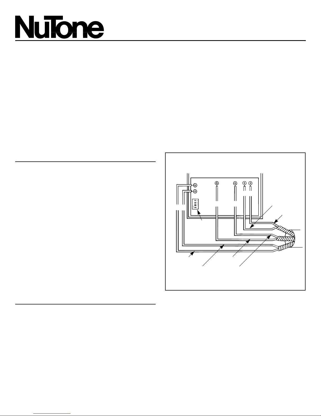
FIGURE 1
DATA
SELECTOR
SWITCH
INTERCOM
AUDIO
RED
RED/WHT
BLK/WHT
BLK
ORN
ORN/WHT
5" Indoor Speaker
MODEL: IS-515 Series
5" Patio Speaker
MODEL: IS-519
For use with NuTone IM-5000 or IM-5006 Intercom Systems.
ROUGH-IN FRAME MOUNTING
The speakers are mounted to the IR-50 Rough-ln
Frame.
New Construction
NOTE: Refer to the instructions packaged with the
rough-in.
The Rough-ln Frame is mounted to a wall stud
during rough-in construction. The wiring is ran to
the speaker location. The speaker is mounted to
the rough-in frame once the wall is in place.
Existing Construction
NOTE: Refer to the instructions packaged with the
rough-in.
The Rough-ln Frame requires a cutout to the
finished wall. The Frame may be mounted either
directly to a wall stud or between the wall studs.
The wiring is installed through the existing walls.
WIRING
RATING: INPUT 19vDC, 40mA
OUTPUT 60mW
Refer to Figure 1. Connect the color-coded wires
from the Master Station to the matching terminal
screws on the speakers printed circuit board.
OFF
POSITION
ON
POSITION
OFF
12345
FIGURE 2
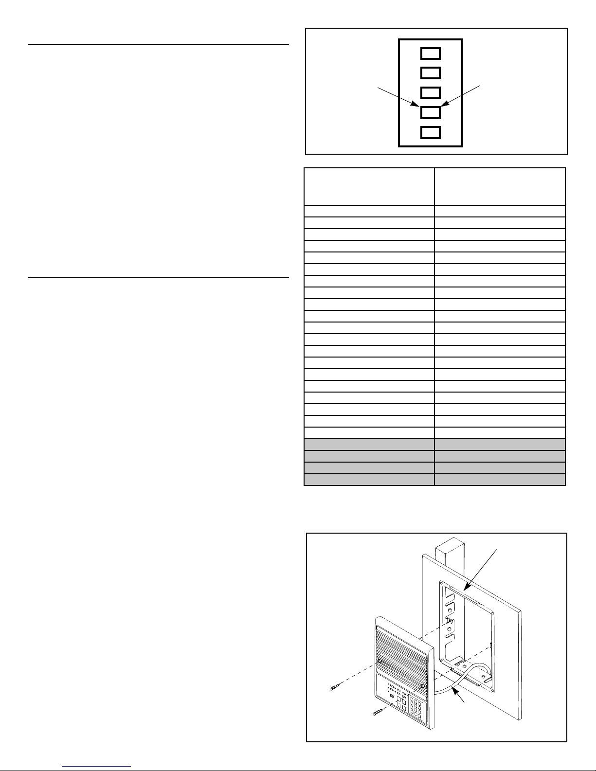
FIGURE 4
IR-50
IW-6
SETTING THE SELECTOR SWITCH
IMPORTANT: Be certain the system has been
disconnected at the main power source prior
to setting the selector switch. Powering the
system up will allow the station identification
to be effective.
IMPORTANT: The Master Station has been preset
as Station #1. The remotes will be station 02
through 21 on the IM-5000 master and 02 through
25 on the IM-5006 master. Do not exceed 21
when using the IM-5000 or the IM-5000/401T
power transformer will be damaged.
1. Refer to Figure 2. Locate the Selector Switch
on the back of the remote control unit.
2. Refer to Figure 3. As indicated in Figure 3, set
the Selector Switch in the ON and OFF
positions.
MOUNTING
Refer to Figure 4.
1. Carefully place wires inside wall.
2. IMPORTANT: Outdoor models must be caulked
with a waterproofing compound (Silicone
Rubber, RTV or equivalent - not supplied by
NuTone). Caulk across the top and both sides
of the unit only; the bottom of the unit should
not be caulked.
3. Using two mounting holes in the sides of the
speaker body, secure the speaker to the frame
with two (2) provided screws.
For operating instructions, refer to the
Radio-lntercom system’s Operator’s Manual. If
Operator’s Manual has been misplaced, write to:
NuTone, Madison and Red Bank Roads,
Cincinnati, Ohio 45227.
FIGURE 3
IF THE REMOTE UNIT IS TO
BE THE STATION NUMBER:
THESE NUMBERS ON THE
SELECTOR SWITCH MUST BE
IN THE ON POSITION
02 2
1 & 2
3
1 & 3
2 & 3
1, 2 & 3
4
1 & 4
2 & 4
1, 2 & 4
3 & 4
1, 3 & 4
2, 3 & 4
1, 2, 3 & 4
5
1 & 5
2 & 5
1, 2 & 5
3 & 5
1, 3 & 5
2, 3 & 5
1, 2, 3 & 5
4 & 5
1, 4 & 5
03
04
05
06
07
08
09
10
11
12
13
14
15
16
17
18
19
20
21
22
23
24
25
NOTE: Shaded area is for IM-5006 only.
 Loading...