

Page 1
INSTALLATION INSTRUCTIONS
GP AND SM6500 SERIES RANGE HOODS
READ & SAVE THESE INTRUCTIONS
INSTALLATION INSTRUCTIONS
WARNING - TO REDUCE THE RISK OF FIRE,
ELECTRIC SHOCK, OR INJURY TO PERSONS,
OBSERVE THE FOLLOWING:
• Installation work and electrical wiring must be done by
qualified person(s) in accordance with all applicable codes and
standards - including fire-rated construction codes and standards.
• Sufficient air is needed for proper combustion and exhausting
of gases through the flue (chimney) of fuel burning equipment
to prevent backdrafting. Follow the heating equipment
manufacturer’s guidelines and safety standards such as those
published by the National Fire Protection Association (NFPA),
and the American Society for Heating, Refrigeration and Air
Conditioning Engineers (ASHRAE), and local code authorities.
• When cutting or drilling into wall or ceiling, do not damage
electrical wiring and other hidden utilities.
• Ducted fans must always be vented to the outdoors.
• To reduce the risk of fire, use only metal ductwork.
• To reduce the risk of fire or electrical shock, this range
hood should not be used with an additional solid-state
speed control device.
WARNING: To reduce the risk of shock, disconnect power before
servicing.
CAUTION: To reduce the risk of fire and to properly exhaust air,
be sure to duct air outside. Do not vent exhaust air
into spaces within walls or ceilings or into attics,
crawl spaces or garages.
IMPORTANT SAFETY INSTRUCTIONS
WARNING - TO REDUCE THE RISK OF FIRE,
ELECTRIC SHOCK, OR INJURY TO PERSONS,
OBSERVE THE FOLLOWING:
• Use this unit only in the manner intended by the manufacturer. If you
have any questions, contact the manufacturer.
• Before servicing or cleaning unit, switch power off at service panel
and lock service panel to prevent power from being switched on
accidentally.
CAUTION
:
For general ventilating only. Do not use to exhaust
hazardous or explosive materials and vapours.
WARNING - TO REDUCE THE RISK OF A RANGE TOP
GREASE FIRE:
• Never leave surface units unattended at high settings. Boilovers
cause smoking and greasy spillovers that may ignite. Heat oils
slowly on low or medium setting.
• Always turn hood ON when cooking at high heat or when flambeing
food (i.e. Crepes Suzette, Cherries Jubilee, Peppercorn Beef Flambé).
• Clean ventilating fans frequently. Grease should not be allowed to
accumulate on fan or filter.
• Use proper pan size. Always use cookware appropriate for the size
of the surface element.
WARNING - TO REDUCE THE RISK OF INJURY TO
PERSONS IN THE EVENT OF A RANGE TOP
GREASE FIRE, OBSERVE THE FOLLOWING*
:
• SMOTHER FLAMES with a close-fitting lid, cookie sheet, or metal
tray, then turn off the burner. BE CAREFUL TO PREVENT BURNS.
If the flames do not go out immediately, EVACUATE AND CALL THE
FIRE DEPARTMENT.
• NEVER PICK UP A FLAMING PAN - you may be burned.
• DO NOT USE WATER, including wet dishcloths or towels - a violent
steam explosion will result.
• Use an extinguisher ONLY if:
1. You know you have a Class ABC extinguisher, and you already
know how to operate it.
2. The fire is small and contained in the area where it started.
3. The fire department is being called.
4. You can fight the fire with your back to an exit.
*Based on “Kitchen Fire Safety Tips” published by NFPA.
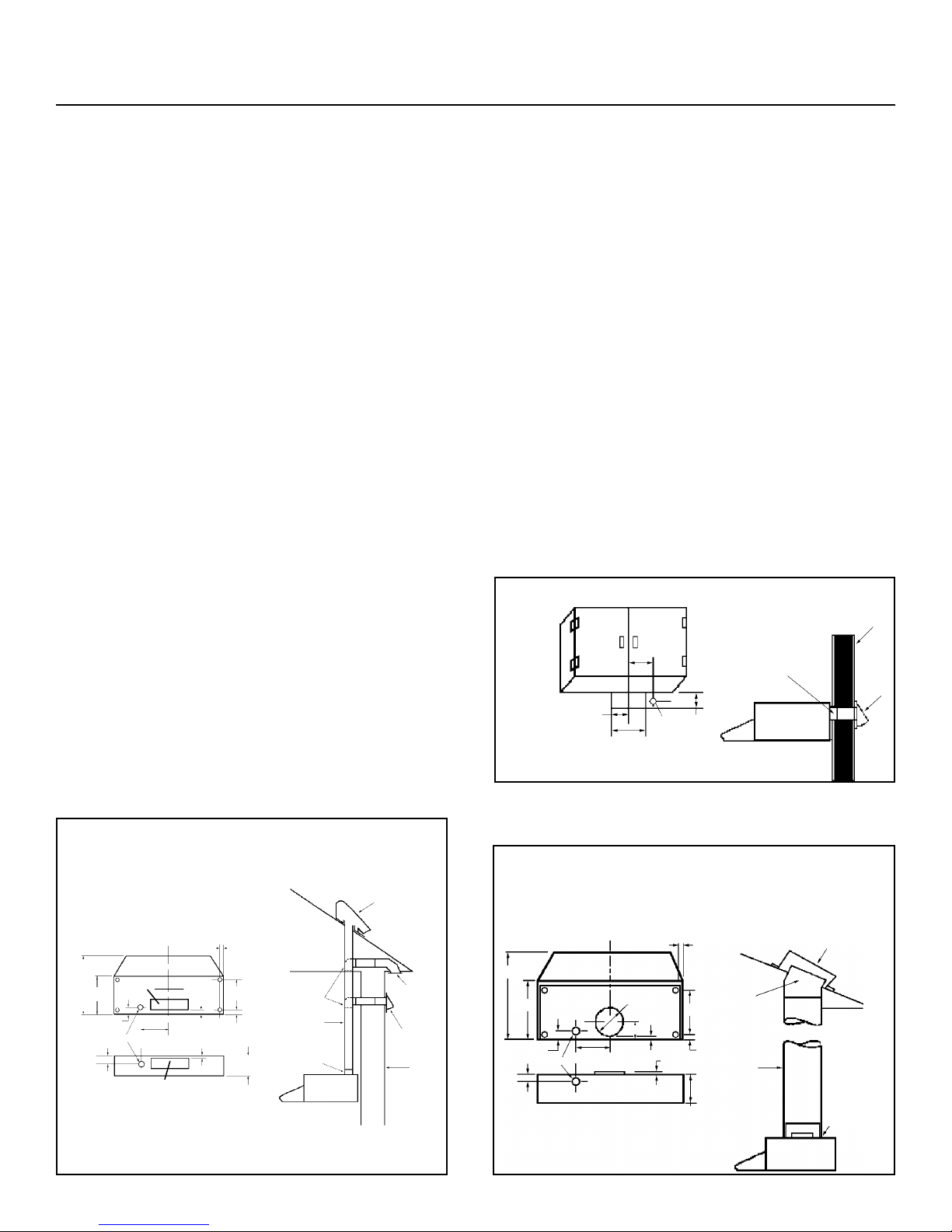
HORIZONTAL DISCHARGE THROUGH WALL
1 1/16”
(27.0 mm)
10 1/4”
(260.4 mm)
3 3/4”
(95.2 mm)
7”
(177.8 mm)
1 7/16”
(36.5 mm)
SUPPLIED
DUCT
TRANSITION
WALL
WALL
CAP
RANGE
HOOD
REMOVE DAMPER
TRANSITION FOR THIS
INSTALLATION
CUTOUT DIMENSIONS
KITCHEN
CABINET
FIGURE 1
VERTICAL DISCHARGE
USING 7” (177.8 mm) ROUND DUCT
(TRANSITION NOT INCLUDED)
FIGURE 3
ROOF CAP
ROOF
CUTOUT DIMENSIONS
ADJUSTABLE
ELBOW
7”
(177.8 mm)
ROUND
DUCT
REMOVE
BOTH 3-1/4”
(82.6 mm) x
8” (203.2 mm)
& 4-1/2”
(114.3 mm) x
8” (203.2 mm)
KNOCKOUTS
FOR 7”
(177.8 mm)
DUCT
RANGE HOOD
12”
(304.8 mm)
18”
(457.2 mm)
1 7/16” (36.5 mm)
ELEC. K.O.
7/8”
(22.2 mm)
9 3/8”
(238.1 mm)
1/2”
(12.7 mm)
6”
(152.4 mm)
CL
CL
7”
(177.8 mm)
1/2”
(12.7 mm)
7” (177.8 mm) DIA.
1 7/16”
(36.5 mm)
30040592D
VERTICAL OR HORIZONTAL DISCHARGE
USING 3-1/4” (82.6 mm) x 10” (254 mm) DUCT
FIGURE 2
CUTOUT DIMENSIONS
ROOF CAP
EAVE CAP
WALL
CAP
WALL
SUPPLIED DUCT
TRANSITION
3
1
/4” (82.6 mm)
x 10” (254 mm)
DUCT
ELBOW
(If required)
RANGE
HOOD
12”
(304.8 mm)
18”
(457.2 mm)
CL
7”
(177.8 mm)
1 7/16” (36.5 mm)
ELEC. K.O.
7/8”
(22.2 mm)
9 3/8”
(238.1 mm)
1”
(25.4 mm)
1/2”
(12.7 mm)
6”
(152.4 mm)
3 1/4”
(82.6 mm)
3 1/4”
(82.6 mm)
1/2”
(12.7 mm)
1 7/16”
(36.5 mm)
1” (25.4 mm)
4 7/8”
(123.8 mm)
Page 2
INSTALLATION INSTRUCTIONS
GP AND SM6500 SERIES RANGE HOODS
PLANNING
• Mounting height MUST BE at a minimum of 22” (558.8 mm) and at a
maximum of 30” (762 mm) above the cooking surface from the bottom
edge of the range hood.
• The hood shall be mounted to the bottom of a standard wall cabinet.
If the hood must be mounted directly to a wall, secure the hood
to wall studs.
• All wiring must be properly grounded. Connection should be made to
a 110-120 VAC lighting circuit (15A) in the circuit breaker or fuse box.
• This range hood is ‘Convertible’, it may be installed as a ducted or
as a non-ducted unit.
IF THE RANGE HOOD IS TO BE DUCTED:
• Ductwork can be installed vertically or horizontally.
• Duct runs should be as short as possible.
• Avoid the use of elbows.
• Use duct tape at all joints.
• Do not use duct smaller than the discharge on the hood.
NON DUCTED:
• Disregard instructions for knockout.
• Discard damper, it will not be used.
PREPARATION
1. Use the dimensional drawing to lay out the range hood’s mounting
holes, wiring access and ductwork.
2. Make cut-outs for wiring and ductwork.
3. If the hood is to be ducted, install the ductwork so that it is flush to
the range hood’s mounting surface.
• Refer to Figure 1 if the range hood is to be installed with a
horizontal discharge.
• Refer to Figure 2 if the range hood is to be installed with a
vertical discharge.
4. Remove the necessary duct opening and wiring knockout from the
range hood.
NOTE: If the range hood is to be installed as a ducted unit
install baffle (Refer to Figure 5) by sliding into place
behind grille. Use locator bumps to orient in grille.
NOTE: If the range hood is to be installed as a ductless unit,
do not remove any knockouts.
5. Run two-conductor wires (with ground) from a power source to the
hood location. Bring approximately 12” (304.8 mm) or wiring through
wiring hole in cabinet.
6. Drill four 3/32” (2.4 mm) diameter pilot holes at points where
mounting holes are marked in the filler strips or cabinet bottom.
7. Insert four (4) mounting screw (not supplied), leaving approximately
1/4” (6.4 mm) of thread exposed. Use No. 8 or No. 10 round head screws.
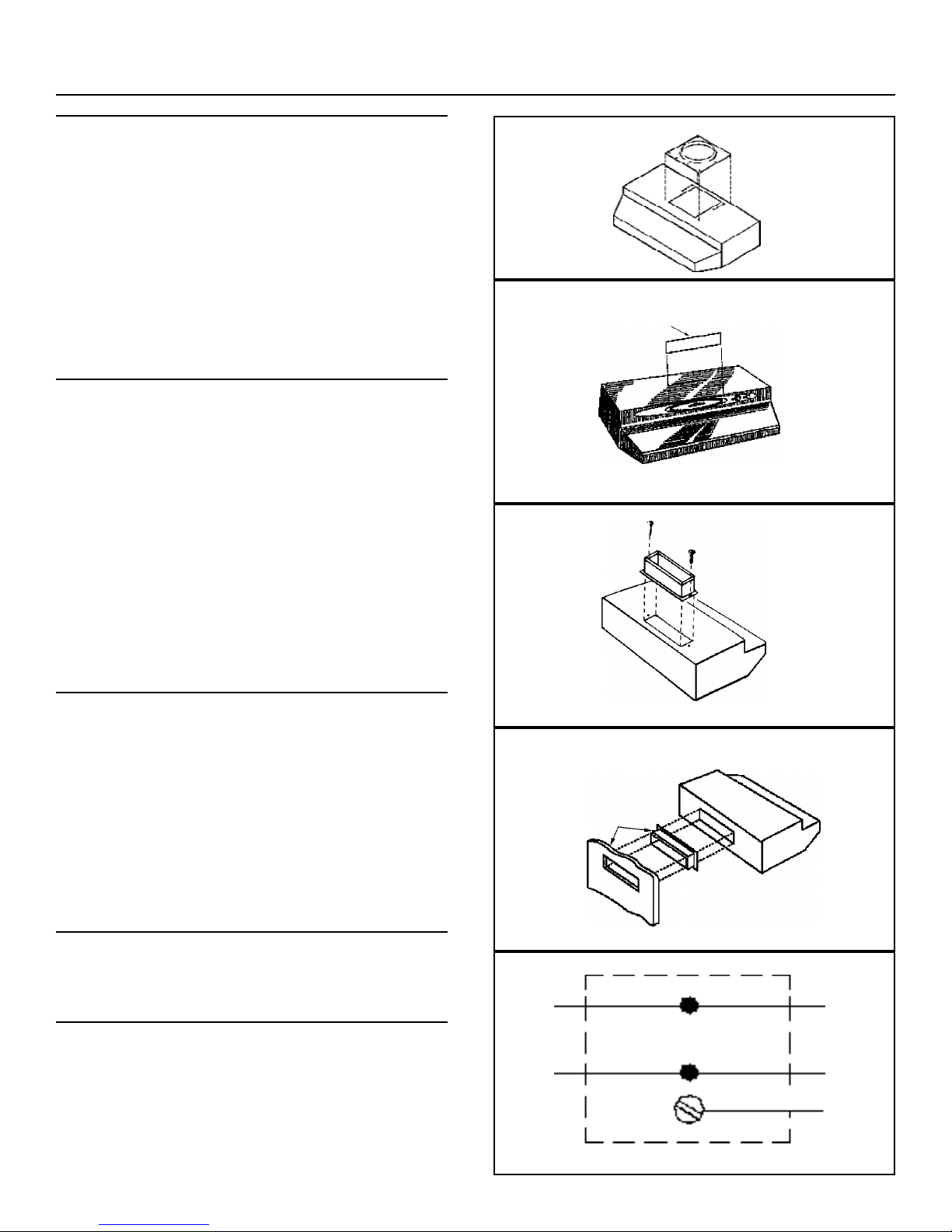
INSTALLATION
1. Refer to Figure 6 for a vertical discharge installation. Secure 3
1/4” (82.6 mm) x 10” (254 mm) transition (if used) to top of hood.
Refer to Figure 7 for a horizontal discharge installation. If
using the supplied 3 1/4” (82.6 mm) x 10” (254 mm) duct
transition, remove the damper from the transition to prevent
possible venting interference. Position transition into wall cutout
(the transition does not fasten the hood).
Refer to Figure 4 for 7” (177.8 mm) round discharge
installation. Secure 7” (177.8 mm) transition to top if hood using
screws provided.
2. Feed the wiring through the access hole and into the electrical box.
3. Align hood’s keyhole mounting slots over the four (4) partially
installed screws.
4. Making sure the duct position over the hood’s duct transition push
the hood against the rear wall. Secure hood by tightening screws.
5. Using a long blade screwdriver, reach into the discharge opening
and make sure the damper operates freely.
WIRING CONNECTIONS
All wiring connections must comply with local code and the unit must
be properly grounded.
1. Make sure box connector is secure.
2. Refer to Figure 8. Make wiring connections.
3. Replace electrical box cover and secure with screw.
COMPLETING ASSEMBLY
1. Install a 75 W (maximum) light bulb in the receptacle.
2. Install filter and light lens assembly.
3. For ductless use with charcoal filter (FKM-65): Install 2 filter
clips by sliding into the receivers on the sides of the hood fan housing.
See Figure 9.
FIGURE 4
7” (177.8 MM)
ROUND ADAPTER
(NOT INCLUDED)
FIGURE 5
INSERT BAFFLE WITH
NOTCHED SIDE UP AND
AWAY FROM THE HOOD
FIGURE 6
SECURE
TRANSITION
WITH SCREWS
WHT
WHT
BLK
BLK
GREEN GROUND
SCREW
GREEN
OR BARE
(GROUND)
HOOD WIRING
SUPPLY WIRING
FIGURE 7
FIGURE 8
POSITION DUCT
TRANSITION IN
WALL CUTOUT
HORIZONTAL
Page 3

FILTER
CLIPS
FKM-65 FILTER
(FOR DUCTLESS
OPERATION ONLY)
ALUMINUM FILTER
Broan-NuTone Canada warrants to the original consumer purchaser of its products that such products will be free from defects in materials and
workmanship for a period of one year from the date of original purchase. THERE ARE NO OTHER WARRANTIES, EXPRESSED OR IMPLIED,
INCLUDING, BUT NOT LIMITED TO, IMPLIED WARRANTIES OF MERCHANTABILITY OR FITNESS FOR A PARTICULAR PURPOSE.
During this one-year period, Broan-NuTone Canada will, at its option, repair or replace, without charge, any product or part which is found to be
defective under normal use and service.
THIS WARRANTY DOES NOT EXTEND TO FLUORESCENT LAMP STARTERS AND TUBES. This warranty does not cover (a) normal maintenance
and service or (b) any products or parts which have been subject to misuse, negligence, accident, improper maintenance or repair (other than by
Broan-NuTone Canada), faulty installation or installation contrary to recommended installation instructions.
The duration of any implied warranty is limited to the one-year period as specified for the express warranty.
BROAN- NUTONE CANADA’S OBLIGATION TO REPAIR OR REPLACE, AT BROAN-NUTONE CANADA’S OPTION, SHALL BE THE PURCHASER'S
SOLE AND EXCLUSIVE REMEDY UNDER THIS WARRANTY. BROAN-NUTONE CANADA SHALL NOT BE LIABLE FOR INCIDENTAL,
CONSEQUENTIAL OR SPECIAL DAMAGES ARISING OUT OF OR IN CONNECTION WITH PRODUCT USE OR PERFORMANCE. Some
jurisdictions do not allow the exclusion or limitation of incidental or consequential damages, so the above limitation or exclusion may not apply to you.
This warranty gives you specific legal rights, and you may also have other rights, which vary by jurisdiction. This warranty supersedes all prior warranties.
To qualify for warranty service, you must (a) notify Broan-NuTone Canada at the address or telephone number below, (b) give the model number and
part identification and (c) describe the nature of any defect in the product or part. At the time of requesting warranty service, you must present evidence
of the original purchase date.
Date of Installation Builder or Installer
Model No. and Product Description
IF YOU NEED ASSISTANCE OR SERVICE:
For the location of your nearest Broan-NuTone Canada Incorporated dealer
Dial Free 1-888-882-7626
Please be prepared to provide:
Product model number • Date and Proof of Purchase • The nature of the difficulty
Broan-NuTone Canada Incorporated
1140 Tristar Drive, Mississauga, Ontario, Canada L5T 1H9
www.broan.ca
OPERATION AND MAINTENANCE
FILTERS
IMPORTANT: The aluminium filter should be removed once a week
and washed in hot detergent water. Rinse in clear, warm water and
shake off excessive moisture before replacing. The filter may also be
cleaned in your dishwasher. Always install the aluminium filter with the
domed side away from the fan.
IN A NON-DUCTED INSTALLATION
Refer to Figure 9. In non-ducted installations use FKM65 filter and
replace every 3-6 months as needed. Always install the FKM65 filter
first (nearest fan) with carbon side towards fan and the aluminium
filter second. Install filter clips by sliding into brackets on side of air
chamber
CLEANING
The hood should be wiped off occasionally both inside and outside
using warm water, mild dish detergent and a soft cloth. Never use
scouring powders, steel wool pads or any other abrasive cleaners,
which will destroy the hood’s finish.
BROAN-NUTONE CANADA ONE-YEAR LIMITED WARRANTY
FIGURE 9
Page 4

ÉVACUATION VERTICALE AVEC
CONDUIT ROND DE 3 ¼ po (82,6 mm) x 10 po (254 mm)
FIGURE 2
DIMENSIONS DE LA DÉCOUPE
12 po
(304.8 mm)
CL
7 po
(177,8 mm)
1 7/16 po (36,5 mm)
ENTRÉES DÉFONÇABLES
ÉLECTRIQUES
7/8 po
(22,2 mm)
9 3/8 po
(238,1 mm)
1 po
(25,4 mm)
1/2 po
(12,7 mm)
6 po
(152,4 mm)
3 1/4 po
(82,6 mm)
3 1/4 po
(82,6 mm)
ÉVACUATION HORIZONTALE À TRAVERS UN MUR
1 1/16 po
(27,0 mm)
10 1/4 po
(260,4 mm)
3 3/4 po
(95,2 mm)
7 po
(177,8 mm)
1 7/16 po
(36,5 mm)
TRANSITION
FOURNIE
HOTTE
RETIRER LE CLAPET
DE LA TRANSITION POUR CETTE
INSTALLATION
DIMENSIONS DE LA DÉCOUPE
ARMOIRE
DE CUISINE
FIGURE 1
LIRE ET CONSERVER CES DIRECTIVES
INSTRUCTIONS D’INSTALLATION
HOTTES DE CUISINIÈRE SÉRIES GP ET SM6500
IMPORTANTES DIRECTIVES DE SÉCURITÉ
AVERTISSEMENT - POUR RÉDUIRE LES RISQUES
D’INCENDIE, D’ÉLECTROCUTION OU DE BLESSURES,
OBSERVEZ LES INSTRUCTIONS SUIVANTES :
• N’utilisez cet appareil que de la façon prévue par le manufacturier. Si vous
avez des questions, contactez le manufacturier à l’une des adresses ou
numéros de téléphone indiqués dans la garantie.
• Avant de nettoyer ou de réparer l’appareil, coupez le courant au panneau
d’alimentation et verrouillez-en l’accès afin d’éviter sa remise en marche
accidentelle. Si le panneau d’alimentation ne peut être verrouillé,
apposez un avertissement bien en évidence, par exemple une étiquette de
couleur vive.
ATTENTION : Pour ventilation générale seulement. Ne l’utilisez pas pour
évacuer des matières ou des vapeurs dangereuses ou explosives.
AVERTISSEMENT - AFIN DE RÉDUIRE LE RISQUE DE FEU
DE CUISINIÈRE :
• Ne laissez jamais les appareils de cuisson sans surveillance lorsqu’ils sont
réglés à feu vif. Les débordements engendrent de la fumée et des
déversements graisseux pouvant s’enflammer. Chauffez l’huile lentement,
à feu doux ou moyen.
• Mettez toujours la hotte en marche lorsque vous cuisinez à feu vif ou que
vous cuisinez des mets flambés (par ex. : crêpes Suzette, cerises jubilé,
steaks au poivre flambé).
• Nettoyez régulièrement la (les) roue(s) du ventilateur. Ne laissez pas la
graisse s’accumuler sur le ventilateur ou le(s) filtre(s).
• Utilisez le bon format de casserole. Servez-vous toujours de casseroles et
d’ustensiles de cuisson appropriés à la dimension de la surface chauffante.
AVERTISSEMENT - POUR RÉDUIRE LES RISQUES DE
BLESSURES LORS D’UN FEU DE CUISINIÈRE,
OBSERVEZ LES INSTRUCTIONS SUIVANTES* :
• ÉTOUFFER LES FLAMMES au moyen d’un couvercle hermétique, d’une plaque
à biscuits ou d’un plateau en métal, puis éteignez le brûleur. ATTENTION DE NE
PAS VOUS BRÛLER. Si les flammes ne s’éteignent pas immédiatement,
SORTEZ ET APPELEZ LES POMPIERS.
• NE PRENEZ JAMAIS EN MAIN UNE POÊLE OU UNE CASSEROLE QUI A
PRIS FEU, vous pourriez vous brûler.
• N’UTILISEZ PAS D’EAU, ni de torchons ou de serviettes mouillés, vous
provoqueriez une violente explosion de vapeur.
• Utiliser un extincteur SEULEMENT LORSQUE :
1. Vous savez qu’il s’agit d’un extincteur de classe ABC et vous en connaissez
le fonctionnement.
2. L’incendie est petit et limité à l’endroit où il a débuté.
3. Les pompiers ont été avisés.
4. Vous pouvez combattre l’incendie en ayant accès à une sortie de secours.
* Tirées du Kitchen Fire Safety Tips (conseils de sécurité pour
éviter les incendies dans une cuisine) publié par la NFPA.
DIRECTIVES D’INSTALLATION
AVERTISSEMENT - POUR RÉDUIRE LES RISQUES
D’INCENDIE, D’ÉLECTROCUTION OU DE BLESSURES,
OBSERVEZ LES INSTRUCTIONS SUIVANTES :
• Les travaux d’installation et de raccordement électrique doivent être effectués
par du personnel qualifié, conformément aux normes et aux règlements en
vigueur, y compris les normes et codes en matière de prévention d’incendie.
• Une circulation d’air efficace est requise afin d’assurer la combustion et
l’évacuation complète des gaz par la cheminée des équipements à combustion
pour prévenir les retours de cheminée. Conformez-vous aux instructions et
aux standards de sécurité des manufacturiers d’équipement de chauffage,
tels qu’ils sont publiés par la National Fire Protection Association (NFPA) et
l’American Society for Heating, Refrigeration and Air Conditioning Engineers
(ASHRAE) ainsi que les responsables des codes locaux.
• Lorsque vous coupez ou perforez un mur ou un plafond, prenez garde de ne
pas endommager les fils électriques ou autre installation qui pourraient y
être dissimulés.
• Les conduits de l’installation doivent toujours évacuer l’air à l’extérieur.
• Afin de réduire le risque d’incendie, n
’utilisez que des conduits en métal.
• N’utilisez pas cet appareil avec une commande de vitesse à semi-conducteur
additionnelle.
AVERTISSEMENT : Avant de procéder à quelconque opération,
débranchez l’appareil.
ATTENTION : Pour réduire le risque d’incendie et d’évacuer
correctement l’air, assurez-vous d’évacuer l’air à
l’extérieur. N’évacuez pas l’air dans des espaces
clos comme l’intérieur des murs ou d’un plafond,
dans le grenier, faux-plafond ou garage.
CAPUCHON
DE TOIT
SORTIE
AVANT-TOIT
CAPUCHON
DE MUR
MUR
COUDE
(si requis)
CONDUIT DE
3 ¼ po (82,6 mm)
x 10 po (254 mm)
HOTTE
TRANSITION
FOURNIE
1 7/16 po
(36,5 mm)
1/2 po
(12,7 mm)
CAPUCHON
MURAL
MUR
ÉVACUATION VERTICALE AVEC
CONDUIT ROND DE 7 PO (177,8 mm)
(TRANSITION NON INCLUSE)
FIGURE 3
CAPUCHON DE TOIT
TOIT
DIMENSIONS DE LA DÉCOUPE
COUDE
RÉGLABLE
CONDUIT
ROND DE
7 po
(177,8 mm)
DÉFONCER LES
ENTRÉES
PRÉAMORCÉES DE
3 1/4 po (82,6 mm) x
8 po (203,2 mm) ET
DE 4 1/2 po (114,3 mm)
x 8 po (203,2 mm)
POUR LE CONDUIT
DE 7 po (177,8 mm)
HOTTE
12 po
(304,8 mm)
18 po
(457,2 mm)
1 7/16 po
(36,5 mm)
entrées
défonçables
élect.
7/8 po
(22,2 mm)
9 3/8 po
(238,1 mm)
1/2 po
(12,7 mm)
6 po
(152,4 mm)
CL
7 po
(177,8 mm)
1/2 po
(12,7 mm)
7 po (177,8 mm) DIA.
1 7/16 po
(36,5 mm)
30040592D
1 po
(25,4 mm)
4 7/8 po
(123,8 mm)
18 po
(457,2 mm)
Page 5

FIGURE 4
ADAPTATEUR ROND
7 po (177,8 mm)
(non inclus)
FIGURE 5
INSÉRER LE DÉFLECTEUR
EN PLAÇANT LE CÔTÉ
COCHÉ VERS LE HAUT.
ÉLOIGNÉ DE LA HOTTE.
FIGURE 6
FIXER LA TRANSITION
AVEC LES VIS
BLANC
NOIR
NOIR
VIS VERTE DE
MISE À LA TERRE
VERTE OU
SANS GAINE
(TERRE)
CÂBLAGE
DE LA HOTTE
CÂBLAGE D’ALIMENTATION
FIGURE 7
FIGURE 8
PLACER LA TRANSITION
DE CONDUIT DANS LA
DÉCOUPE MURALE
À L’HORIZONTALE
INSTRUCTIONS D’INSTALLATION
HOTTES DE CUISINIÈRE SÉRIES GP ET SM6500
PLANIFICATION DE L’INSTALLATION
• La base de la hotte DOIT ÊTRE installée à un minimum de 22 po
(558,8 mm) et à un maximum de 30 po (762 mm) au-dessus de la surface
de cuisson.
• La hotte doit être installée au bas d’une armoire de cuisine standard.
Si la hotte doit être installée directement au mur, la fixer aux montants.
• Le branchement doit être mis à la terre. La hotte doit être branchée
à un circuit d’éclairage de 110-120 V c.a. (15 A) qui se trouve dans
le panneau de distribution électrique ou la boîte de fusibles.
• Cette hotte de cuisine peut être installée avec ou sans conduit
d’évacuation
SI LA HOTTE EST INSTALLÉE AVEC UN CONDUIT D’ÉVACUATION
• Le conduit peut être installé à la verticale ou à l’horizontale.
• Utiliser le conduit le plus court possible.
• Éviter d’utiliser des coudes.
• Sceller hermétiquement les joints à l’aide de ruban à conduits.
• Ne pas utiliser un conduit au diamètre inférieure à celui de la
sortie de la hotte.
SANS CONDUIT :
• Ne pas tenir compte des instructions pour les entrées défonçables.
• Mettre de côté le raccord. Il ne sera pas utilisé.
PRÉPARATION
1. Utiliser le gabarit pour déterminer l’emplacement des trous pour
le montage, le passage des fils et le passage du conduit.
2. Découper les ouvertures pour le branchement et le conduit.
3. Si la hotte est installée avec un conduit, installer ce dernier pour qu’il
soit à égalité avec la surface de montage de la hotte.
• Voir la Figure 1 si la hotte est installée avec une évacuation
horizontale.
• Voir la Figure 2 si la hotte est installée avec une évacuation
verticale.
4. Enlever l’ouverture préamorcée appropriée pour le conduit ainsi que
les entrées défonçables pour le branchement.
NOTE: Si la hotte es installée avec un conduit, installer le
déflecteur (voir la Figure 5) en le glissant en place derrière la
grille. Utiliser les pivots de localisation pour orienter la grille.
NOTE: Si la hotte est installée sans conduit, n’enlever aucune
entrée défonçable.
5. Installer un fil à deux conducteurs (avec mise à la terre) de la source
d’alimentation à la hotte. Faire passer environ 12 po (304,8 mm) de
fil dans l’ouverture de branchement.
6. Percer quatre avant-trous de 3/32 po (2,4 mm) de diamètre là où
vous avez marqué l’emplacement des orifices de montage sur les
languettes de bois ou au bas de l’armoire.
7. Insérer quatre (4) vis de montage (non fournies) dans les orifices, en
laissant dépasser environ 1/4 po (6,4 mm) de filet. Utiliser des vis
no 8 ou 10 à tête ronde.
INSTALLATION
1. Voir la Figure 6 pour une évacuation verticale. Fixer la transition
de 3 1/4 po (82,6 mm) x 10 po (254 mm) (au besoin) sur le
dessus de la hotte. Voir la Figure 7 pour une installation à
évacuation horizontale. Si vous utilisez la transition de 3 1/4 po
(82,6 mm) x 10 po (254 mm), retirer le clapet de la transition pour
éviter les interférences de ventilation. Placer la transition dans
l’ouverture du mur (la transition ne doit pas supporter la hotte).
Voir la Figure 4 pour l’installation de la sortie ronde de 7 po
(177,8 mm). Fixer la transition de 7 po (177,8 mm) sur le dessus
de la hotte à l’aide des vis fournies.
2. Faire passer le fil électrique par l’orifice d’accès, puis dans la boîte électrique.
3. Aligner les fentes de montage en forme de trous de serrure avec les
quatre vis partiellement vissées.
4. Vous assurer que le conduit soit bien vis-à-vis la transition, pousser
la hotte contre le mur arrière, puis la fixer en place en serrant les vis.
5. Au moyen d’un long tournevis, vérifier que le clapet fonctionne
librement en passant par la sortie de la hotte.
BRANCHEMENT ÉLECTRIQUE
Toutes les connexions électriques doivent être conformes aux codes
locaux en vigueur, et la hotte doit être correctement mise à la terre.
1. S’assurer que le connecteur de boîte soit bien branché et bien fixé.
2. Voir la Figure 8. Effectuer les connexions électriques.
3. Replacer le couvercle de la boîte électrique et le fixer à l’aide de la vis.
COMPLÉTER L’ASSEMBLAGE
1. Installer une ampoule de 75 W (maximum) dans la douille.
2. Installer le filtre et le couvercle de l’ampoule.
3. Pour les hottes sans conduit, utiliser un filtre à charbon
FKM-65. Fixer les deux loquets du filtre en les glissant dans les
réceptacles de chaque côté du boîtier du ventilateur. Voir Figure 9.
BLANC
Page 6

Broan-NuTone Canada garantit à l’acheteur consommateur original, de ses produits qu’ils sont exempts de tout défaut dans les matières premières ou
la main-d’œuvre pour une période de un an à compter de la date d’achat originale. IL N’Y A PAS D’AUTRES GARANTIES, EXPRIMÉES OU
IMPLICITES, INCLUANT MAIS NON PAS LIMITÉE AUX GARANTIES IMPLICITES POUR FIN DE COMMERCIALISATION ET DE CONVENANCE
DANS UN BUT PARTICULIER.
Pendant cette période de un an, Broan-NuTone Canada, à son choix, réparera ou remplacera, gratuitement, tout produit ou pièce qui s’avère défectueux
sous utilisation et service normaux.
CETTE GARANTIE NE COUVRE PAS LES STARTERS DE LAMPES FLUORESCENTES ET LES TUBES. Cette garantie ne couvre pas (a) l’entretien
et le service normal ou (b) tout produit ou pièce endommagé à la suite d’un mauvais usage, de négligence, d’un accident, d’un entretien inapproprié ou
d’une réparation (autre que par Broan-NuTone Canada), d’une installation inadéquate ou contraire au mode d’installation recommandé.
La durée de toute garantie implicite est limitée à une période de un an telle qu’elle est spécifiée pour la garantie exprimée.
L’ENGAGEMENT DE BROAN-NUTONE CANADA DE RÉPARER OU DE REMPLACER, AU CHOIX DE BROAN-NUTONE CANADA, SERA LA SEULE
OBLIGATION EXCLUSIVE SOUS CETTE GARANTIE. BROAN-NUTONE CANADA NE SERA PAS TENUE RESPONSABLE DES DOMMAGES
DIRECTS, INDIRECTS OU SPÉCIAUX SURVENANT À CAUSE DE OU EN RAPPORT AVEC L’UTILISATION OU LA PERFORMANCE DE SES
PRODUITS. Certaines juridictions ne permettent pas l’exclusion ou la limitation de responsabilité relative aux dommages directs ou indirects.
Par conséquent, l’exclusion ou la limitation énoncée ci-dessus peut ne pas s’appliquer à votre cas.
Cette garantie vous donne des droits légaux spécifiques et il se peut que vous ayez d’autres droits variant selon la juridiction. Cette garantie annule
toutes les garanties précédentes.
Pour le service sous garantie, vous devez (a) aviser Broan-NuTone Canada à l’adresse ou au numéro de téléphone ci-dessous, (b) donner le numéro
du modèle et l’identification de la pièce et (c) décrire la nature de tout défaut dans le produit ou la pièce. Au moment de demander le service sous
garantie, vous devez présenter une preuve de la date d’achat originale.
Date d’installation Entrepreneur ou installateur
N
o
de modèle et description du produit
POUR OBTENIR DE L’ASSISTANCE OU DU SERVICE
Pour connaître le Centre de services Broan-NuTone Canada Inc. autorisé indépendant le plus près de chez vous :
Composez le numéro sans frais : 1 888 882-7626
Garder à portée de la main le numéro du modèle, la date et la preuve d’achat, le type de problème.
Broan-NuTone Canada Incorporated
1140, Tristar Drive, Mississauga (Ontario) CANADA L5T 1H9
www.broan.ca
LOQUETS DU
FILTRE
FILTRE FKM-65
(HOTTE SANS
CONDUIT SEULEMENT)
FILTRE EN ALUMINIUM
UTILISATION ET ENTRETIEN
FILTRES
IMPORTANT: Le filtre en aluminium doit être enlevé une fois par
semaine pour être nettoyé avec un détergent et de l’eau chaude. Rincer
à l’eau tiède, puis secouer pour enlever l’excédent d’eau avant de le
remettre en place. Le filtre va également au lave-vaisselle. Installer
toujours le filtre en aluminium avec la partie bombée à l’opposé du
ventilateur.
HOTTE SANS CONDUIT
Voir la Figure 9. Avec une hotte sans conduit, utiliser le filtre à charbon
et le remplacer tous les 3 à 6 mois au besoin. Installer toujours le filtre
à charbon FKM-65 en premier (près du ventilateur), côté à charbon
vers le ventilateur, suivi du filtre en aluminium. Fixer les loquets du
filtre en les glissant dans les brides de chaque côté du boîtier
du ventilateur.
NETTOYAGE
La hotte doit être nettoyée à l’occasion, à l’extérieur comme à
l’intérieur avec de l’eau tiède, un détergent doux et un chiffon doux.
Ne jamais utiliser de poudre à récurer, de tampon de laine d’acier ou
de nettoyants abrasifs, car cela pourrait endommager le fini de la
FIGURE 9
GARANTIE LIMITÉE DE UN AN DE BROAN-NUTONE CANADA
 Loading...