

Page 1
READ AND SAVE THESE INSTRUCTIONS
Installer: leave this guide with homeowner.
Register your product online at www.nutone.ca/register.asp
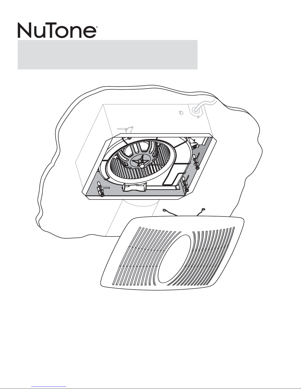
EZ80NC
EZ Fit
Ventilation Fan
INSTALLATION GUIDE
Easy installation
© 2014 Broan-NuTone LLC
Table of Contents
Warnings and Cautions 2
Operation 2
Cleaning and Maintenance 2
Troubleshooting 2
Typical Installation 2
Installation - Replace an Existing Fan 3
Installation - New Construction 7
Service Parts 8
Warranty 8
Page 2
Page 2
EZ80NC
Installation Guide
WARNING
TO REDUCE THE RISK OF FIRE, ELECTRIC SHOCK, OR
INJURY TO PERSONS, OBSERVE THE FOLLOWING:
1. Use this unit only in the manner intended by the manufacturer.
If you have questions, contact the manufacturer at the
address or telephone number listed in the warranty.
2. Before servicing or cleaning unit, switch power off at service
panel and lock the service disconnecting means to prevent
power from being switched on accidentally. When the service
disconnecting means cannot be locked, securely fasten
a prominent warning device, such as a tag, to the service
panel.
3. Installation work and electrical wiring must be done by a
qualified person(s) in accordance with all applicable codes
and standards, including fire-rated construction codes and
standards.
4. Sufficient air is needed for proper combustion and exhausting
of gases through the flue (chimney) of fuel burning equipment
to prevent backdrafting. Follow the heating equipment
manufacturer’s guideline and safety standards such as those
published by the National Fire Protection Association (NFPA),
and the American Society for Heating, Refrigeration and
Air Conditioning Engineers (ASHRAE), and the local code
authorities.
5. When cutting or drilling into a ceiling, do not damage electrical
wiring and other hidden utilities.
6. Ducted fans must always be vented to the outdoors.
7. Acceptable for use over a tub or shower (in the ceiling only)
when connected to a GFCI (Ground Fault Circuit Interrupter)
- protected branch circuit.
8. Use an ON/OFF switch to operate this ventilator. Use of
speed controls may cause a humming noise.
9. This unit must be grounded.
CAUTION
1. For general ventilating use only. Do not use to exhaust
hazardous or explosive materials and vapors.
2. DO NOT install this unit onto an acoustic ceiling panel.
3. When installed in a sloped ceiling, the duct connector must
point up.
4. To avoid motor bearing damage and noisy and/or
unbalanced impellers, keep drywall spray, construction
dust, etc. off power unit.
5. Please read specification label on product for further
information and requirements.
!
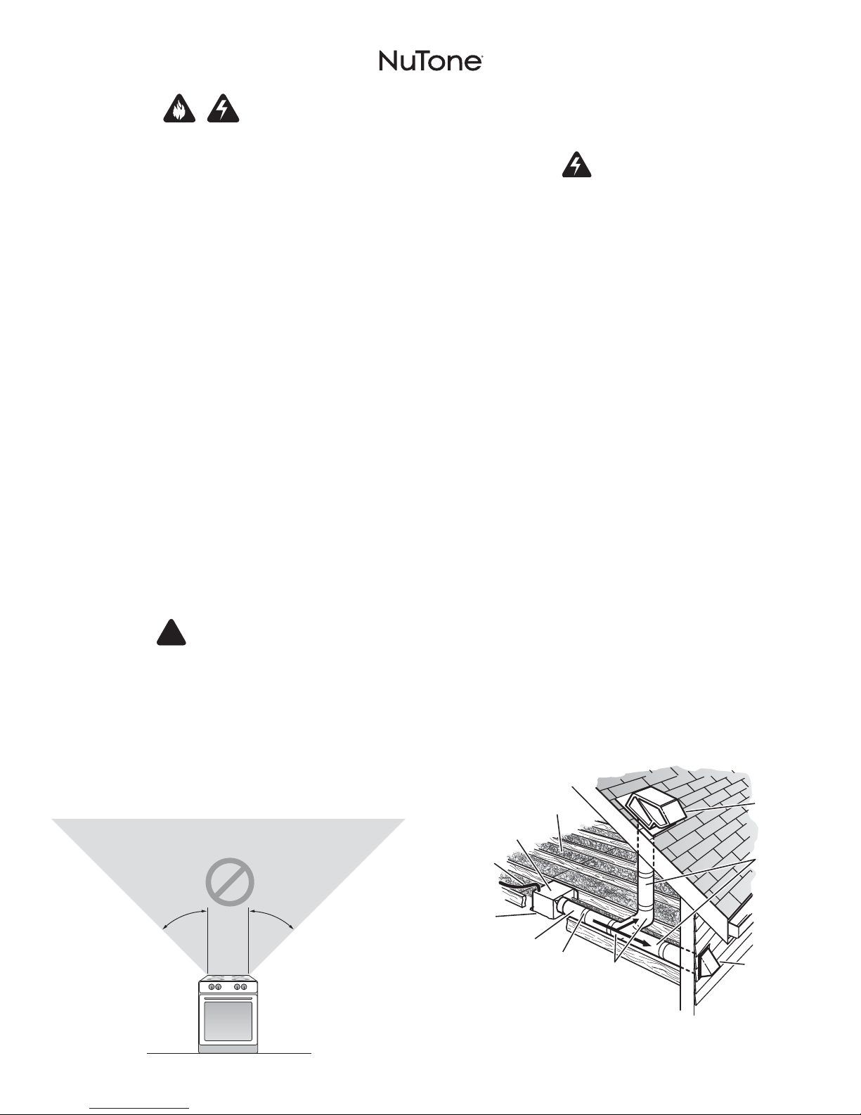
NOT FOR USE IN A COOKING AREA
Do not install above or inside this area
Operation
To Operate Fan
Use an ON/OFF switch to operate this ventilator.
WARNING Before servicing or cleaning unit,
switch power off at service panel and lock the service
disconnecting means to prevent power from being switched on
accidentally. When the service disconnecting means cannot be
locked, securely fasten a prominent warning device, such as a
tag, to the service panel.
Cleaning and Maintenance
To Clean
For quiet and efficient operation, long life and attractive
appearance, remove grille and vacuum interior of unit with a
dusting brush attachment.
The motor is permanently lubricated and never needs oiling. If
the motor bearings are making excessive or unusual noises,
replace the motor.
Troubleshooting
Symptom: The fan does not run.
• Check for an open fuse or circuit breaker in the building’s
service panel.
• Check that the plug-in connection for the motor is seated
firmly in place.
• Check that the blower wheel spins freely.
Symptom: The fan runs erratically.
• Check that the blower wheel is firmly attached to the motor
shaft and both spin freely.
Symptom: The fan seems noisy.
• Check that the back draft damper in the fan’s duct connector
pivots freely. Screws used to attach the ducting to the duct
connector may be preventing the damper from opening.
• Check that the back draft damper in the wall or roof cap pivots
freely. These dampers are sometimes mistakenly painted shut
or obstructed by bird and insect debris.
Typical Installation
POWER
CABLE*
HOUSING
INSULATION*
(Place around and
over Fan Housing.)
FAN
ROOF CAP*
(with built-in
damper)
Keep duct
runs short.
45° 45°
Cooking
Equipment
Floor
Seal gaps
around
Housing.
*Purchase
separately.
ROUND
DUCT*
Seal duct
joints with
tape.
ROUND
ELBOWS*
OR
WALL CAP*
(with built-in
damper)
Page 3
Page 3
Installation - Replace an Existing Fan
EZ80NC
Installation Guide
Tools needed
• Phillips screwdriver
• Hammer or pry bar
• Safety glasses
• Pencil
• Tape Measure
• Drywall saw
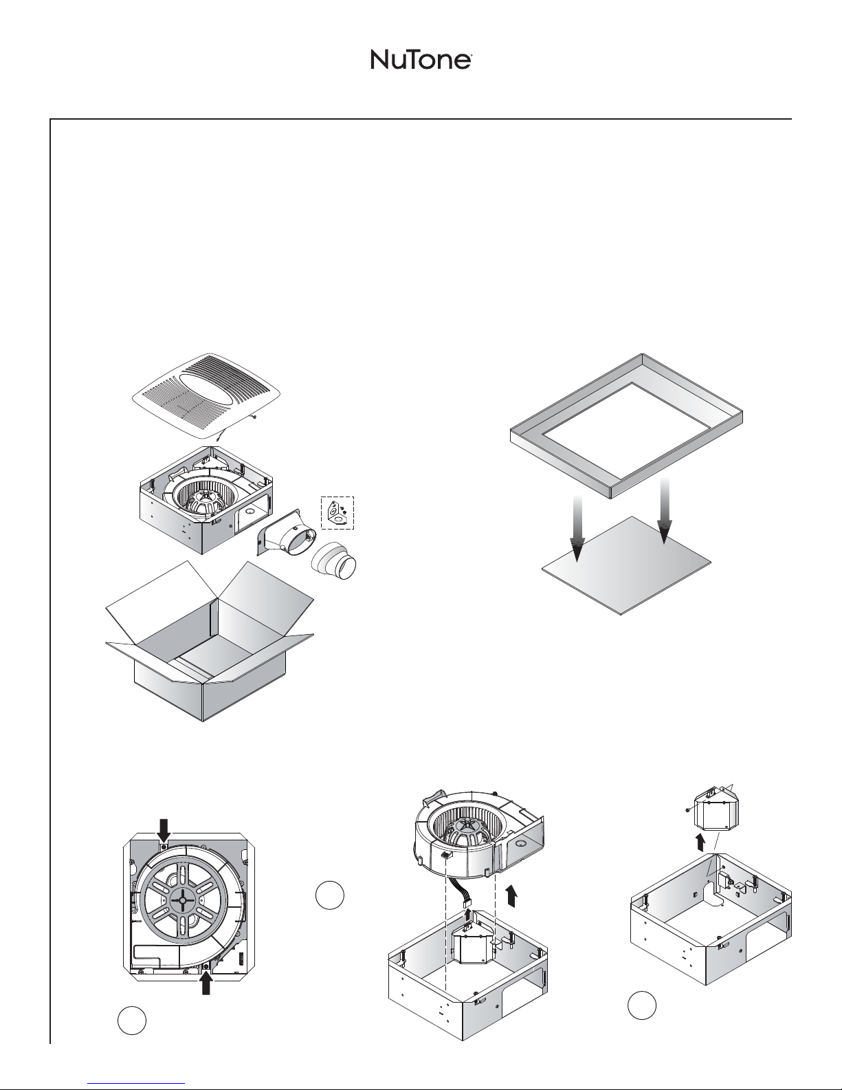
Remove from Packaging
1
Materials needed
• 4" round metal ducting recommended for best performance. Use of
other ducting is acceptable but may impact performance. Existing
metal duct will require the addition of a short lenght of flexible duct.
• Roof cap or wall cap (built-in damper recommended)
• Tape to seal duct connections
• Drywall screws or sheet metal screws (optional)
• Electrical wiring and supplies per local code requirements
Punch out
Template from
packaging. See
Step 3.
Prepare the Housing
2
Loosen 2 blower
1
screws.
Unplug blower
2
and remove
blower from
housing.
Remove wiring cover.
3
Page 4

Page 4
Installation - Replace an Existing Fan
Mark Ceiling Using Template
3
Make sure existing
JOIST
8¼” MAX.
1
fan is no larger
than 8” x 8¼”.
JOIST
EZ80NC
Installation Guide
Mark center line
2
of existing fan
on ceiling.
C
L
12¼”
10¾”
For retrofit installations: Place this edge against ceiling framing.
(See installation instructions.)
Position
3
template over
existing fan with
arrow on center line.
CENTER LINE
OF INSTALLATION
8” MAX.
LOCATION OF
NEW FAN’S
DUCT CONNECTOR
Cut Ceiling Opening & Remove Old Fan
4
For retrofit installations: Place this edge against ceiling framing.
(See installation instructions.)
CENTER LINE
OF INSTALLATION
Trace around outside
4
of template with a
pencil.
LOCATION OF
NEW FAN’S
DUCT CONNECTOR
C
L
JOIST
Use a drywall saw to
1
cut out ceiling material
where marked.
WARNING
Be careful to avoid cutting through
electrical wiring or ductwork.
JOIST
Disconnect electrical
2
wiring and ductwork then remove existing fan.
Page 5

Page 5
Installation - Replace an Existing Fan
Install New Housing
5
Lift new fan
housing up into
1
enlarged opening in
ceiling material.
Hold housing firmly up
against ceiling material
and carefully tighten
4 clamps with a Phillips
screwdriver.
2
EZ80NC
When turned clockwise (with a Phillips screwdriver), clamps
will spin outward from housing and move downward on top of
ceiling material to properly secure housing in place. Minimum
ceiling thickness to be 1/2”.
CAUTION: Do not overtighten clamps with a power driver.
Ceiling material may become deformed and prevent
proper installation.
Installation Guide
Connect Ductwork
6
Insert duct
2
connector into
opening and fasten
to housing with
tab and screw
provided.
Pull ductwork into housing and use duct tape to
attach it to duct connector.
1
For 3” ductwork, use the 4” to 3” reducer (provided).
See below.
4" to 3"
Reducer
3" Ducting
Tape
(provided)
Tape
4" Duct
Connector
Page 6

Page 6
Installation - Replace an Existing Fan
EZ80NC
Installation Guide
Connect Electrical Wiring
7
WARNING
TO REDUCE THE RISK OF FIRE, ELECTRIC SHOCK, OR
INJURY TO PERSONS, OBSERVE THE FOLLOWING:
If unfamiliar with electrical wiring, secure the services of a
qualified person to connect wiring according to all applicable
codes and standards.
Connect house wiring to
wiring plate with UL approved
connector.
Connect wiring as
shown in diagrams.
Attach wiring plate and wiring
cover to inside of housing with
screws provided.
120 VAC
LINE IN
Install Grille
9
Squeeze
grille springs
1
and insert
into slots in
blower.
BLACK
WHITE
ON/OFF
SWITCH
(purchase separately)
GROUND (green or bare)
SWITCH BOX
120 VAC LINE IN
Replace Blower
8
KNOCKOUT
PLATE
RECEPTACLE
Plug blower
into receptacle
and re-install
blower. Tighten
blower screws.
Push grille up against ceiling.
2
Page 7

Page 7
Installation - New Construction
Remove from Packaging (see Page 3)
1
Prepare the Housing (see Page 3)
2
Install Fan Housing & Connect Ductwork
3
Insert duct
1
connector
into opening
and fasten
to housing
with tab
and screw
provided.
EZ80NC
Position fan against ceiling framing so that bottom edge of
housing will be flush with finished ceiling.
3
Use 4 screws to attach housing to framing.
Optional for additional support: After ceiling is finished,
rotate the tightening clamps as described on Page 5.
Installation Guide
Attach housing to 2" x 6" or greater joists.
2
Use additional blocking as needed.
JOISTS I-JOISTS TRUSSES
ADDITIONAL BLOCKING
Connect Electrical Wiring (see Page 6)
4
Replace Blower (see Page 6)
5
Use duct tape to connect ductwork to duct connector.
4
For 3” ductwork, use the 4” to 3” reducer (provided). See
below.
Tape
Tape
3" Ducting
4" to 3"
Reducer
(provided)
Connect ductwork to a roof or wall cap.
5
4" Duct
Connector
Install Grille (see Page 6)
6
Page 8

Page 8
EZ80NC
Installation Guide
Service Parts
1
2
3
5
7
Key No. Part No. Description
1 79110158 4” to 3” Reducer
2 97019326 Wiring Plate
3 77001297 Capacitor
4 77001447 Tightening Clamps (4)
5 97019006 Wiring Cover Assembly
6 77001277 Duct Connector Assembly
7 97019349 Blower Assembly
8 79140014 Grille Spring (2)
9 97019525 Grille Assembly
(includes key no. 8)
Order replacement parts by Part No., not by Key No.
4
6
8
Warranty
Limited Warranty
Warranty Period and Exclusions: Broan-NuTone Canada Inc. (the “Company”) warrants to the
original consumer purchaser of its product (“you”) that the product (the “Product”) will be free
from material defects in the Product or its workmanship for a period of one (1) year from the date
of original purchase.
The limited warranty period for any replacement parts provided by the Company and for any Products
repaired or replaced under this limited warranty shall be the remainder of the original warranty period.
This warranty does not cover speed controls, fluorescent lamp starters, tubes, halogen and
incandescent bulbs, fuses, filters, ducts, roof caps, wall caps and other accessories for ducting
that may be purchased separately and installed with the Product. This warranty also does not cover
(a) normal maintenance and
have been subject to misuse, abuse, abnormal usage, negligence, accident, improper or insufficient
maintenance, storage or repair (other than repair by the Company), (d)damage caused by faulty
installation, or installation or use contrary to recommendations or instructions, (e) any Product
that has been moved from its original point of installation, (f) damage caused by environmental
or natural elements, (g)damage in transit, (h)natural wear of finish, (i)Products in commercial or
nonresidential use, or (j)damage caused by fire, flood or other act of God. This warranty covers only
Products sold to original consumers in Canada by the Company or Canadian distributors authorized
by the Company.
This warranty supersedes all prior warranties and is not transferable from the original consumer
purchaser.
No Other Warranties: This Limited Warranty contains the Company’s sole obligation and your
sole remedy for defective products. The foregoing warranties are exclusive and in lieu of any other
warranties, express or implied. THE COMPANY DISCLAIMS AND EXCLUDES ALL OTHER EXPRESS
WARRANTIES, AND DISCLAIMS AND EXCLUDES ALL WARRANTIES IMPLIED BY LAW, INCLUDING
WITHOUT LIMITATION THOSE OF MERCHANTABILITY AND FITNESS FOR A PARTICULAR PURPOSE.
To the extent that applicable law prohibits the exclusion of implied warranties, the duration of any
applicable implied warranty is limited to the period specified for the express warranty above. Some
provinces do not allow limitations on how long an implied warranty lasts, so the above limitation may
not apply to you. Any oral or written description of the Product is for the sole purpose of identifying
it and shall not be construed as an express warranty.
Whenever possible, each provision of this Limited Warranty shall be interpreted in such manner as to
be effective and valid under applicable law, but if any provision is held to be prohibited or invalid, such
provision shall be ineffective only to the extent of such prohibition or invalidity, without invalidating
the remainder of such provision or the other remaining provisions of the Limited Warranty.
Remedy: During the applicable limited warranty period, the Company will, at its option, provide
replacement parts for, or repair or replace, without charge, any Product or part thereof, to the extent
the Company finds it to be covered by and in breach of this limited warranty under normal use and
service. The Company will ship the repaired or replaced Product or replacement parts to you at
no charge. You are responsible for all costs for removal, reinstallation and shipping, insurance or
other freight charges incurred in the shipment of the Product or part to the Company. If you must
send the Product or part to the Company, as instructed by the Company, you must properly pack
the Product or part—the Company is not responsible for damage in transit. The Company reserves
the right to utilize reconditioned, refurbished, repaired or remanufactured Products or parts in the
warranty repair or replacement process. Such Products and parts will be comparable in function and
performance to an original Product or part and warranted for the remainder of the original warranty
period.
Exclusion of Damages: THE COMPANY’S OBLIGATION TO PROVIDE REPLACEMENT PARTS, OR
REPAIR OR REPLACE, AT THE COMPANY’S OPTION, SHALL BE YOUR SOLE AND EXCLUSIVE
9
REMEDY UNDER THIS LIMITED WARRANTY AND THE COMPANY’S SOLE AND EXCLUSIVE
OBLIGATION. THE COMPANY SHALL NOT BE LIABLE FOR INCIDENTAL, INDIRECT, CONSEQUENTIAL
OR SPECIAL DAMAGES ARISING OUT OF OR IN CONNECTION WITH THE PRODUCT, ITS USE OR
PERFORMANCE.
Some provinces do not allow the exclusion or limitation of incidental or consequential damages, so
the above limitation or exclusion may not apply to you. This warranty gives you specific legal rights,
and you may also have other rights, which vary from province to another.
This warranty covers only replacement or repair of defective Products or parts thereof at the
Company’s main facility and does not include the cost of field service travel and living expenses.
Any assistance the Company provides to or procures for you outside the terms, limitations or
exclusions of this limited warranty will not constitute a waiver of such terms, limitations or exclusions,
nor will such assistance extend or revive the warranty.
The Company will not reimburse you for any expenses incurred by you in repairing or replacing any
defective Product, except for those incurred with the Company’s prior written permission.
How to Obtain Warranty Service: To qualify for warranty service, you must (a)notify the Company
at the address or telephone number stated below within seven (7)days of discovering the covered
defect, (b)give the model number and part identification and (c)describe the nature of any defect
in the Product or part. At the time of requesting warranty service, you must present evidence of the
original purchase date. If you cannot provide a copy of the original written limited warranty, then
the terms of the Company’s most current written limited warranty for your particular product will
control.The most current limited written warranties for the Company’s products can be found at
www.nutone.ca.
Broan-NuTone Canada Inc. 1140 Tristar Drive, Mississauga, ON www.nutone.ca 877-896-1119
service, (b) normal wear and tear, (c)any Products or parts which
79040274A
 Loading...