

Page 1
PROFESSIONAL 2-CHANNEL
MIXER WITH EFFECTS LOOP
QUICKSTART GUIDE
ENGLISH ( 1 – 4 )
GUÍA DE INICIO RÁPIDO
ESPAÑOL ( 5 – 8 )
GUIDE D’UTILISATION SIMPLIFIÉ
FRANÇAIS ( 9 – 12 )
GUIDA RAPIDA
ITALIANO ( 13 – 16 )
KURZANLEITUNG
DEUTSCH ( 17 – 20 )
Page 2

Page 3

1
INTRODUCTION
Welcome to the PRO SMX, a professional 2-channel mixer. Here are just a few features that you’ll come to love
about this device:
Fully analog audio signal path
Pre-/post-effects send and return jacks allow you to use external effects processors
3 inputs per channel (line, phono, and balanced ¼”), all gold-plated
RCA and balanced XLR master outputs
RCA AUX IN (“session input”) with volume control
3-band EQ for each channel with button to switch between ±12dB or +12/–∞dB (i.e. the EQ knobs can be used
traditionally or as frequency kills)
Mini-crossfader cueing
Smooth Pro-X-fade crossfader with adjustable end points and torque
Reverse switches and continuous rotary slope control for crossfader and line faders
We hope that the PRO SMX serves you well for many years to come.
Sincerely,
The People of Numark
BOX CONTENTS
PRO SMX
DC Power Adapter
Quickstart Guide
Safety & Warranty Information Booklet
REGISTRATION
Please go to http://www.numark.com to register your PRO SMX. Registering your product ensures that we can keep
you up-to-date with any last-minute product developments and provide you with world-class technical support, should
you run into any problems.
GROUND RULES
1. Make sure all items listed in the BOX CONTENTS section are included in the box.
2. READ SAFETY & WARRANTY INFORMATION BOOKLET BEFORE USING THE PRODUCT.
3. Study the connection diagram in this guide.
4. Place mixer in an appropriate position for operation.
5. Make sure all devices are turned off and all faders and gain knobs are set to “zero”
6. Connect all stereo input sources as indicated in the diagram.
7. Connect the stereo outputs to power amplifier(s), tape decks, and/or other audio sources.
8. Plug all devices into AC power.
9. Switch everything on in the following order.
• Audio input sources (i.e. turntables, CD players, etc.)
• Mixer
• Last, any amplifiers or output devices
10. When turning off, always reverse this operation by,
• Turning off amplifiers
• Mixer
• Last, any input devices
Page 4
2
NORMAL
FILTERS
FLANGER
AUTOPAN
LR
AUTOCUT
FILTERED
LOPASS
VARI-CUT
RATE
RATE
volume
m1
m2
pitch
xyz
-
+
octave
accomp
store
tap
phrase
latch
analog modeling synth
push
r
h
y
t
h
m
s
p
a
t
t
e
r
n
s
p
r
o
g
r
a
m
s
s
e
t
u
p
s
c
o
n
f
i
g
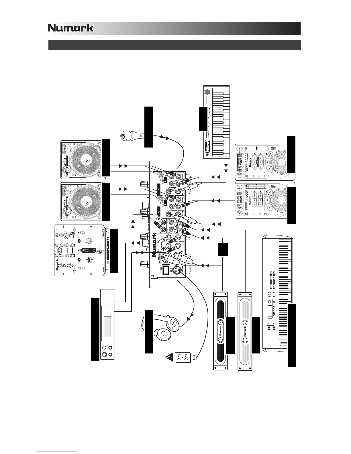
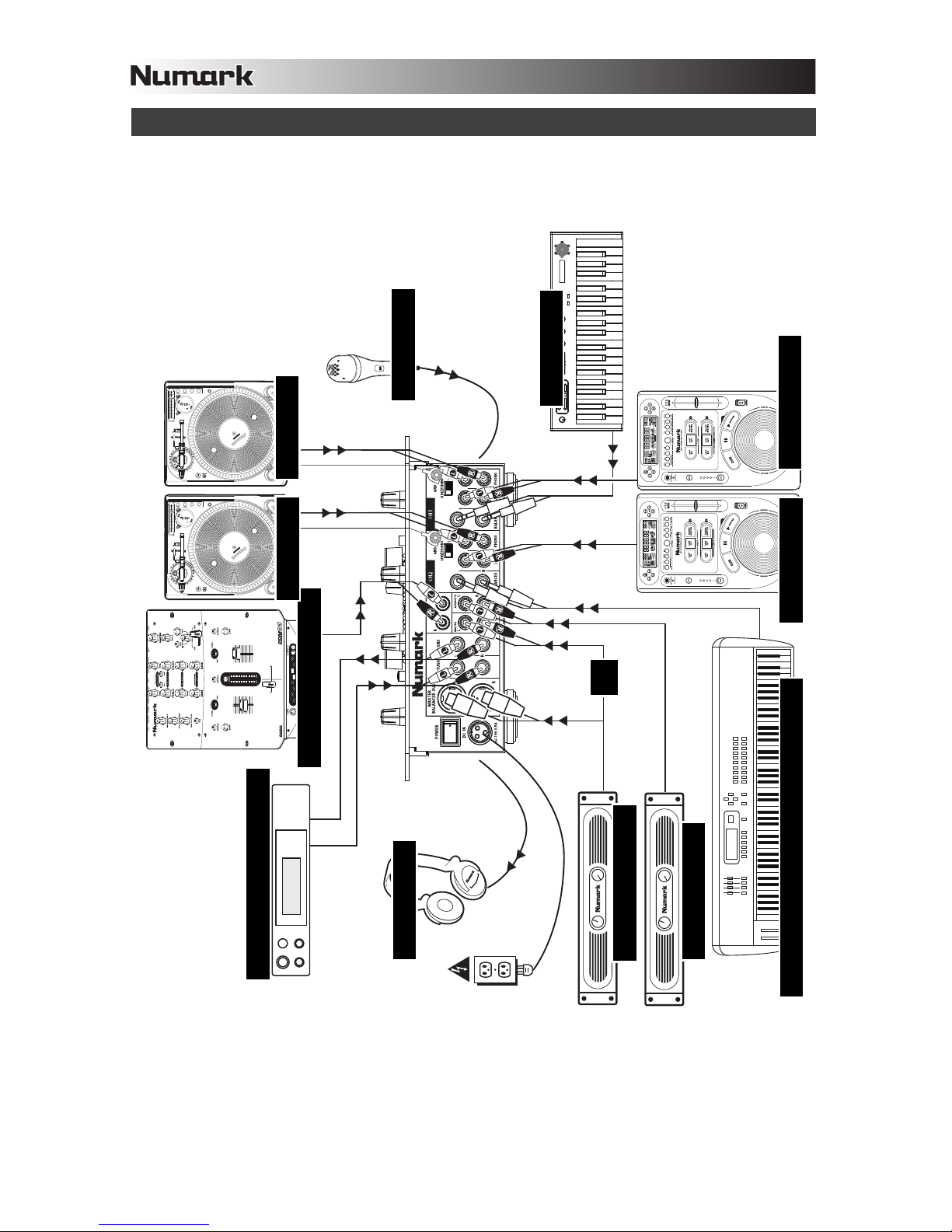
CONNECTION DIAGRAM
MICROPHONE
SYNTH
CD PLAYER
CD PLAYER
SYNTH WORKSTATION
BOOTH AMP
HOUSE AMP
HEADPHONES
EFFECTS PROCESSOR
REMOTE MIXER
TURNTABLE
TURNTABLE
OR
Page 5
3
How do I know if my ¼” cables
are balanced?
BALANCED
UNBALANCED
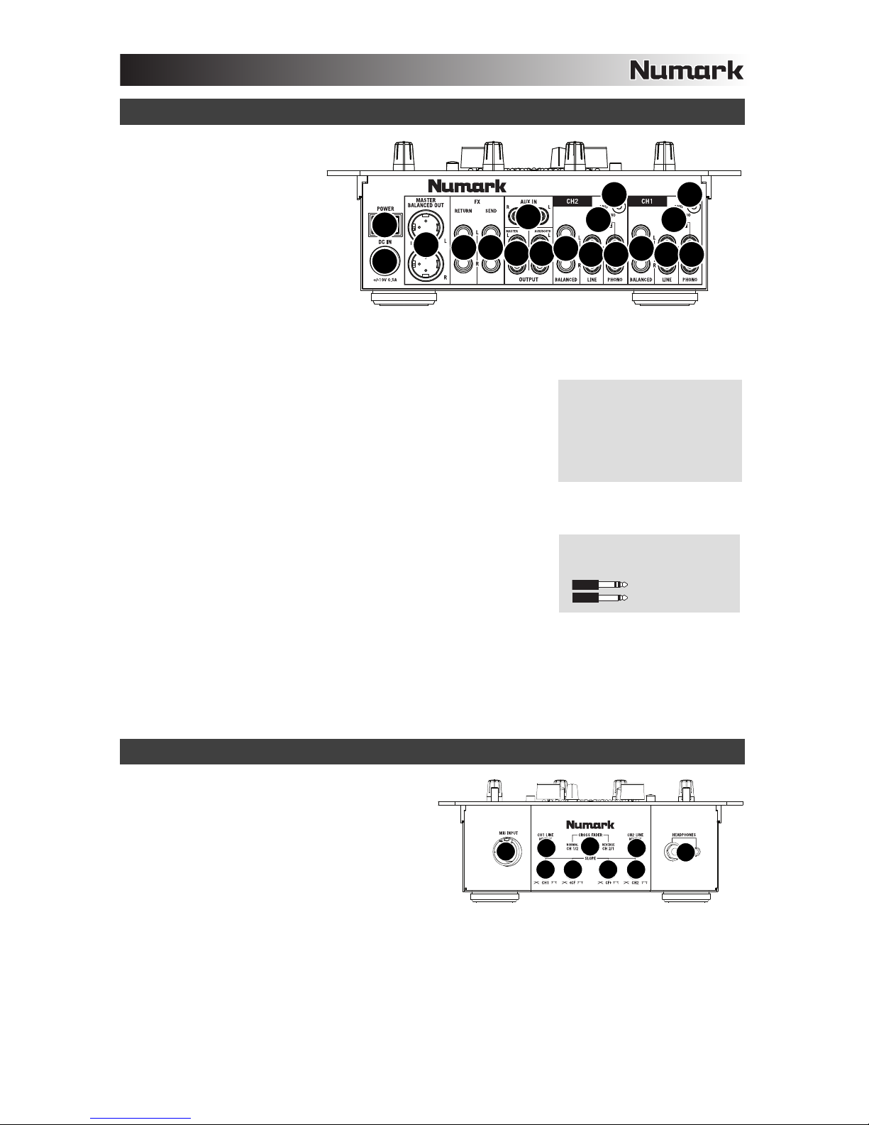
REAR PANEL FEATURES
1. POWER SWITCH – Turns the
mixer on and off. Turn on the
mixer after all input devices
have been connected and
before you turn on amplifiers.
Turn off amplifiers before you
turn off the mixer
2. DC IN – Use the included
power adapter to connect the
mixer to a power outlet. While
the power is switched off, plug
the power supply into the mixer
first, then plug the power
supply into a power outlet.
Note: The mixer is designed to work with the included DC power supply only. Using an incompatible power supply could
result in damage to the unit.
3. MASTER OUTPUT (BALANCED) – Connect this low-impedance XLR output to a PA system or powered monitors. The
level of this output is controlled with the MASTER knob on the top panel.
4. FX SEND – Connect the inputs of an external effects unit to these outputs
using ¼” cables.
5. FX RETURN – Connect the outputs of an external effects unit to these outputs
using ¼” cables.
6. AUX IN (RCA) – Connect line-level or phono devices to these inputs.
7. MASTER OUTPUT (RCA) – Use standard RCA cables to connect this output
to a speaker or amplifier system. The level of this output is controlled by the
MASTER knob on the top panel.
8. AUX / BOOTH OUTPUT (RCA) – Use standard RCA cables to connect this output to a booth amp or other monitoring
system. The level of this output is controlled by the AUX / BOOTH OUTPUT knob on the top panel.
9. LINE INPUTS (BALANCED) – Use standard ¼” cables to connect line-level
devices with balanced outputs, such as synths or keyboards, to these inputs.
10. LINE INPUTS (RCA) – Connect line-level devices, such as CD players,
samplers or audio interfaces, to these inputs.
11. LINE | PHONO INPUTS (RCA) – Connect your audio sources to these inputs.
These inputs can accept both line and phono-level signals.
12. LINE | PHONO SWITCH – Flip this switch to the appropriate position, depending on the device connected to the LINE |
PHONO INPUTS. If you are using phono-level turntables, set this switch to “PHONO” to provide the additional
amplification needed for phono-level signals. If using a line-level device, such as a CD player or sampler, set this switch
to “LINE.”
13. GROUNDING TERMINAL – If using phono-level turntables with a grounding wire, connect the grounding wire to these
terminals. If you experience a low “hum” or “buzz”, this could mean that your turntables are not grounded.
Note: Some turntables have a grounding wire built into the RCA connection and, therefore, nothing needs to be
connected to the grounding terminal.
FRONT PANEL FEATURES
1. MIC INPUT – Connect an XLR or ¼” microphone to
this input. Microphone controls are located on the top
panel.
2. CHANNEL FADER REVERSE – Changes the
direction of the corresponding channel fader. When
pressed, the audio level of the corresponding channel
will decrease when you move the fader up or increase
when you move the fader down.
3. CHANNEL FADER SLOPE – Adjusts the slope of the
CHANNEL FADERS. Turn to the left for a smooth
fade (mixing) or to the right for a sharp cut (scratching).
4. CROSSFADER (CF) MODE – Reverses the assignment of Channels 1 and 2 on the crossfader.
5. CROSSFADER (CF) SLOPE – Adjusts the slope of the CROSSFADER curve. Turn to the left for a smooth fade
(mixing) or to the right for a sharp cut (scratching).
6. HEADPHONES – Connect your ¼” or 1/8” headphones to these outputs for cueing and mix monitoring. Headphone
output controls are located on the top panel.
If nothing is connected to the FX
SEND or FX RETURN jacks, the
audio signal will be automatically
bridged between them. This way,
the signal will be uninterrupted if
the FX SEND switch is
accidentally engaged.
1
2
3
5 4
7 8
9
10 11
13
12
9
10 11
13
12
6
1
2 2
3 35 5
6
4
Page 6
4
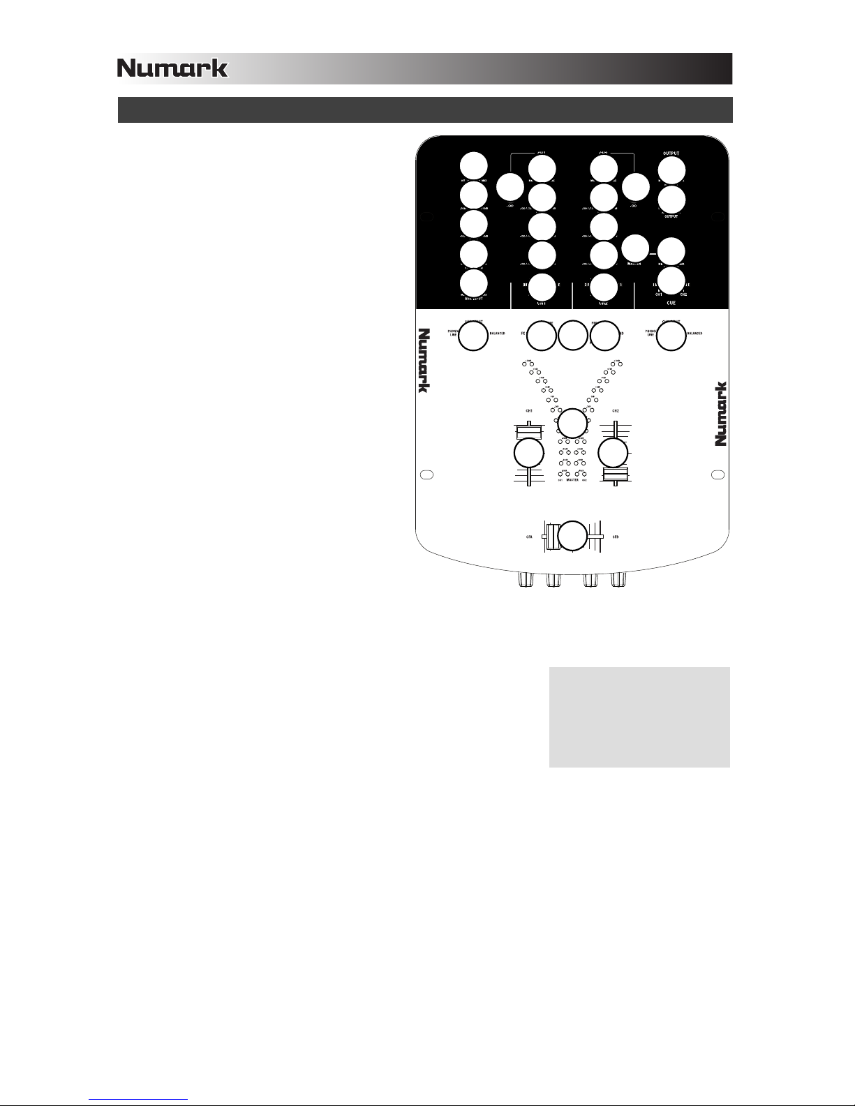
TOP PANEL FEATURES
1. POWER LED – Illuminates when the mixer is on.
2. MIC GAIN – Adjusts the audio level of the
microphone signal.
3. MIC TREBLE – Adjusts the high (treble)
frequencies of the microphone channel.
Tip: If you experience feedback when using a
microphone at loud levels, try turning down the
high frequencies.
4. MIC BASS – Adjusts the low (bass) frequencies of
the microphone channel.
5. FX RETURN – Adjusts the audio level of the signal
sent through the FX RETURN inputs on the rear
panel.
6. AUX INPUT – Adjusts the audio level of the signal
sent through the AUX IN inputs on the rear panel.
7. CHANNEL GAIN – Adjusts the corresponding
channel’s pre-fader and pre-EQ gain level.
8. CHANNEL TREBLE – Adjusts the high (treble)
frequencies of the corresponding channel.
9. CHANNEL MID – Adjusts the mid-range
frequencies of the corresponding channel.
10. CHANNEL BASS – Adjusts the low (bass)
frequencies of the corresponding channel.
11. CHANNEL BALANCE – Adjusts the balance of
right to left audio of the corresponding channel in
all outputs (MASTER, FX, and AUX / BOOTH
OUTPUTS).
12. EQ -12dB / KILL SWITCH – Determines the range
of the CHANNEL EQ knobs. When pressed, the
lowest setting on the EQ knobs will be “zero” (a red
LED on the button will illuminate). When raised,
the lowest setting on the EQ knobs will be -12dB.
Note: The highest setting on all the EQ knobs is
always +12dB.
13. INPUT SELECTOR – Selects the input source to be routed to the corresponding channel. Input jacks are located on the
rear panel.
14. FX SEND – Selects whether the signal from the corresponding channel is routed to the FX SEND outputs.
• OFF – The signal is sent directly to the CHANNEL FADER then to the
Program mix.
• POST – The signal is sent to the CHANNEL FADER, then to the FX SEND
output, then to the FX RETURN input, then to the Program mix.
• PRE – The signal is sent to the FX SEND output, then to the FX RETURN
input. This signal is then combined with the same signal sent directly to the
CHANNEL FADER. Both are then sent to the Program mix.
15. CHANNEL FADER – Adjusts the audio level on the corresponding channel.
16. LED METERS – Monitors the audio levels. The outer two meters monitor the levels of each channel. The inner two
meters monitor the Program mix.
17. CROSSFADER – Blends audio between the channels assigned to the left and right side of the crossfader.
Note: The crossfader is user-replaceable if it should ever wear out. Simply remove the facepanel, then remove the
screws holding it in position. Replace the fader with a quality authorized replacement from your local Numark retailer
only.
18. MASTER – Adjusts the output volume of the Program mix.
19. AUX / BOOTH OUTPUT – Adjusts the audio level sent to the AUX / BOOTH OUTPUT on the rear panel. This signal is
identitcal to the MASTER OUTPUT.
20. MASTER BUTTON – When pressed, this button sends the Program mix to the headphones (a red LED on the button
will illuminate). When raised, the Cue channel is sent to the headphones.
21. CUE GAIN – Adjusts the volume level of the headphone output.
22. CUE SLIDER – Previews the audio playing on Channels 1 and 2. Sliding this to the left plays Channel 1. Sliding to the
right plays Channel 2.
If nothing is connected to the FX
SEND or FX RETURN jacks, the
audio signal will be automatically
bridged between them. This way,
the signal will be uninterrupted if
the FX SEND switch is
accidentally engaged.
1
2
7
12
12
12
12
13
13
14
14
15
15
15
15
16
16
17
17
18
18
19
19
21
21
22
22
20
20
14
14
13
13
8
9
10
10
11
11
7
8
9
10
10
11
11
3
4
5
6
Page 7

5
INTRODUCCIÓN
Bienvenido al mezclador profesional de 2 canales PRO SMX. He aquí algunas de las características de este
dispositivo que seguramente le encantarán:
Trayecto de señal de audio totalmente analógico
Conectores de envío y retorno de efectos pre-/post que le permiten usar procesadores de efectos externos
3 entradas por canal (línea, fonográfica y ¼” balanceada), todas enchapadas en oro
Salidas maestras RCA y XLR balanceadas
Entrada RCA AUX (“entrada de sesión” con control de volumen
Ecualizador de 3 bandas para cada canal con botón para conmutar entre ±12 dB o +12/–∞ dB (es decir, las
perillas del ecualizador se pueden usar tradicionalmente o como de supresión “kill”)
Búsqueda de punto inicial (cue) con mini crossfader
Suave crossfader Pro-X-Fader con puntos terminales y torque ajustables
Conmutadores de reversa y control de pendiente rotativo continuo del crossfader y faders de línea
Esperamos que el PRO SMX le brinde un buen servicio por muchos años.
Atentamente,
La Gente de Numark
CONTENIDO DE LA CAJA
PRO SMX
Adaptador de CC
Guía de inicio rápido
Folleto de información sobre la seguridad y la garantía
REGISTRO
Visite http://www.numark.com y registre su PRO SMX. El registro de su producto asegura que podamos mantenerle
actualizado con los desarrollos de productos de último momento y brindarle apoyo técnico de categoría mundial en
caso de que tenga algún problema.
REGLAS BÁSICAS
1. Asegúrese de que todos los artículos indicados en “Contenido de la caja" estén incluidos en la caja.
2. LEA EL FOLLETO DE INFORMACIÓN SOBRE LA SEGURIDAD Y LA GARANTÍA ANTES DE UTILIZAR EL
PRODUCTO.
3. Estudie el diagrama de conexión incluido en esta guía.
4. Coloque el mezclador en una posición adecuada para su funcionamiento.
5. Asegúrese que todos los dispositivos estén apagados y que todos los faders y perillas de ganancia estén en
posición «cero».
6. Conecte todas las fuentes de entrada estéreo como se indica en el diagrama.
7. Conecte las salidas estéreo a los amplificadores de potencia, bandejas de cinta magnética y/o otras fuentes de
audio.
8. Enchufe todos los dispositivos al suministro de corriente alterna.
9. Encienda todo en el siguiente orden:
y fuentes de entrada de audio (por ejemplo, giradiscos, reproductores de CD, etc.)
y el mezclador
y por último, cualquier amplificador o dispositivo de salida
10. Al apagar, realice siempre esta operación en sentido inverso:
y apague los amplificadores
y el mezclador
y por último, cualquier dispositivo de entrada
Page 8
6
NORMAL
FILTERS
FLANGER
AUTOPAN
LR
AUTOCUT
FILTERED
LOPASS
VARI-CUT
RATE
RATE
volume
m1
m2
pitch
xyz
-
+
octave
accomp
store
tap
phrase
latch
analog modeling synth
push
r
h
y
t
h
m
s
p
a
t
t
e
r
n
s
p
r
o
g
r
a
m
s
s
e
t
u
p
s
c
o
n
f
i
g
DIAGRAMA DE CONEXIÓN
MICRÓFONO
SINTETIZADOR
REPROD DE CD
REPROD DE CD
EST DE TRABAJO SINTETIZADOR
AMP DE CABINA
AMP DE AUDITORIO
AURICULARES
PROCESADOR DE EFECTOS
MEZCLADOR REMOTO
GIRADISCOS
GIRADISCOS
O
Page 9

7
¿Cómo sé si mis cables de ¼”
son balanceados?
BALANCEADO
DESBALANCEADO
CARACTERÍSTICAS DEL PANEL TRASERO
1. INTERRUPTOR DE ENCENDIDO
– Enciende y apaga el mezclador.
Encienda el mezclador después
de desconectar todos los
dispositivos de entrada y antes de
encender los amplificadores.
Apague los amplificadores antes
de apagar el mezclador.
2. ENTRADA DE CC - Use el
adaptador de alimentación incluido
para conectar el mezclador a un
tomacorriente alimentado. Con la
alimentación eléctrica
desconectada, enchufe la fuente de alimentación al mezclador primero, y luego al tomacorriente.
Nota: El mezclador está diseñado para funcionar con la fuente de alimentación de CC incluida únicamente. Si usa una
fuente de alimentación incompatible se puede dañar la unidad.
3. SALIDA MAESTRA (BALANCEADA) - Esta salida XLR de baja impedancia sirve para conectar a un sistema de
megafonía o monitores alimentados. El nivel de esta salida se controla con la perilla MASTER del panel superior.
4. ENVÍO DE EFECTOS – Conecte las entradas de una unidad de efectos
externa a estas salidas con cables de ¼”.
5. RETORNO DE EFECTOS – Conecte las salidas de una unidad de efectos
externa a estas salidas con cables de ¼”.
6. ENTRADA AUX (RCA) – Conecte dispositivos de nivel de línea o fonográfico a
estas entradas.
7. SALIDA MAESTRA (RCA) – Use cables RCA estándar para conectar esta
salida a un sistema de altavoces o amplificador. El nivel de esta salida se
controla con la perilla MASTER del panel superior.
8. SALIDA PARA AUX / CABINA (RCA) – Use cables RCA estándar para conectar esta salida a un amplificador de
cabina o a otro sistema de monitoreo. El nivel de esta salida se controla con la perilla AUX / BOOTH OUTPUT del panel
superior.
9. ENTRADAS DE LÍNEA (BALANCEADAS) – Use cables ¼” estándar para
conectar dispositivos de nivel de línea con salidas balanceadas, tales como
sintetizadores o teclados, a estas entradas.
10. ENTRADAS DE LÍNEA (RCA) – Estas entradas se usan para conectar
dispositivos de nivel de línea, tales como reproductores de CD, muestreadores
o interfaces de audio.
11. ENTRADAS DE LÍNEA | FONOGRÁFICA (RCA) – Conecte sus fuentes de audio a estas entradas. Estas entradas
pueden aceptar señales de nivel de línea y fonográfico.
12. CONMUTADOR DE ENTRADA DE LÍNEA | FONOGRÁFICA – Coloque este conmutador en la posición apropiada, en
función del dispositivo conectado a las entradas DE LÍNEA | FONOGRÁFICA. Si usa giradiscos de nivel fonográfico,
coloque este conmutador en “PHONO” para proporcionar la amplificación adicional necesaria para las señales de este
nivel. Si usa un dispositivo de nivel de línea, tal como un reproductor de CD o muestreador, coloque este conmutador
en “LINE”.
13. TERMINAL DE TIERRA – Si usa giradiscos de nivel fonográfico con cable de conexión a tierra, conecte dicho cable a
estos terminales. Si se experimenta un zumbido grave, puede significar que sus giradiscos no están conectados a
tierra.
Nota: Algunos giradiscos tienen el cable de conexión a tierra incorporado a la conexión RCA y, por lo tanto, no es
necesario conectar nada al terminal de tierra.
CARACTERÍSTICAS DEL PANEL FRONTAL
1. ENTRADA DE MICRÓFONO – Conecte un micrófono
XLR o de 1/4” a esta entrada. Los controles de
micrófono se encuentran en el panel superior.
2. REVERSA DEL FADER DE CANAL – Cambia el
sentido del fader del canal correspondiente. Cuando
se pulsa, el nivel de audio del canal correspondiente
disminuye cuando usted sube el fader y aumenta
cuando lo baja.
3. PENDIENTE DEL FADER DE CANAL – Ajusta la
pendiente de los FADERS DE CANAL. Conmute el
control a la izquierda para una fusión suave (mezcla) o a la derecha para un corte abrupto (rayado).
4. MODO DE CROSSFADER (CF) – Invierte la asignación de los canales 1 y 2 en el crossfader.
5. PENDIENTE DE CROSSFADER (CF) – Ajusta la pendiente de la curva del CROSSFADER. Conmute el control a la
izquierda para una fusión suave (mezcla) o a la derecha para un corte abrupto (rayado).
6. AURICULARES – Conecte sus auriculares de ¼” o 1/8” a estas salidas para búsqueda de punto inicial (cue) y
monitoreo de la mezcla. Los controles de la salida para auriculares se encuentran en el panel superior.
1
2
3
5 4
7 8
9
10 11
13
12
9
10 11
13
12
6
Si no se conecta nada a los
conectores FX SEND o FX
RETURN, la señal de audio se
puentea automáticamente entre
ellos. De esta manera, la señal no
será interrumpida si se acciona
accidentalmente el interruptor FX.
1
2 2
3 35 5
6
4
Page 10

8
CARACTERÍSTICAS DEL PANEL SUPERIOR
1. LED DE ENCENDIDO – Se ilumina cuando el mezclador
está encendido.
2. GANANCIA DE MICRÓFONO – Ajusta el nivel de audio
de la señal de micrófono.
3. AGUDOS DE MICRÓFONO – Ajusta las altas
frecuencias (agudos) del canal de micrófono.
Consejo: Si experimenta realimentación cuando usa un
micrófono con niveles altos, pruebe disminuyendo las
altas frecuencias.
4. GRAVES DE MICRÓFONO – Ajusta las bajas
frecuencias (graves) del canal de micrófono.
5. RETORNO DE EFECTOS – Ajusta el nivel de audio de
la señal enviada a través de las entradas FX RETURN
(Retorno de efectos) del panel trasero.
6. ENTRADA AUX – Ajusta el nivel de audio de la señal
enviada a través de las entradas AUX IN (Entrada aux)
del panel trasero.
7. GANANCIA DE CANAL – Ajusta el nivel de ganancia
pre-fader y pre-ecualización del canal correspondiente.
8. AGUDOS DE CANAL – Ajusta las altas frecuencias
(agudos) del canal correspondiente.
9. FRECUENCIAS MEDIAS DE CANAL – Ajusta las
frecuencias medias del canal correspondiente.
10. GRAVES DE CANAL – Ajusta las bajas frecuencias
(graves) de la señal del canal correspondiente.
11. BALANCE DE CANAL – Ajusta el balance del audio
izquierdo a derecho del canal correspondiente en todas
las salidas (MAESTRA, EFECTOS y AUX / CABINA).
12. CONMUTADOR -12dB / SUPRESIÓN DEL
ECUALIZADOR – Determina el rango de las perillas
CHANNEL EQ (Ecualizador de canal). Cuando se
pulsa, el ajuste más bajo de las perillas del ecualizador será “cero” (se enciende un LED rojo del botón). Cuando se
levanta, el ajuste más bajo de las perillas del ecualizador es de -12 dB.
Nota: El ajuste más alto de todas las perillas del ecualizador es +12dB.
13. SELECTOR DE ENTRADAS – Permite seleccionar la fuente de entrada que se aplica al canal correspondiente. Los
conectores de entrada se encuentran en el panel trasero.
14. ENVÍO DE EFECTOS – Selecciona si la señal del canal correspondiente se aplica a las salidas FX SEND (Envío de
efectos).
• OFF – La señal se envía directamente al FADER DE CANAL y luego a la
mezcla de programa.
• POST – La señal se envía al FADER DE CANAL y luego a la salida FX
SEND (Envío de efectos), luego a la entrada FX RETURN (Retorno de
efectos) y luego a la mezcla de programa.
• PRE – La señal se envía a la salida FX SEND y luego a la entrada FX
RETURN. Esta señal se combina luego con la misma señal enviada
directamente al FADER DE CANAL. Ambas se envían luego a la mezcla
de programa.
15. FADER DE CANAL – Ajusta el nivel de audio del canal correspondiente.
16. MEDIDOR CON LED – Monitorea los niveles de audio. Los dos medidores exteriores monitorean los niveles de cada
canal. Los dos interiores monitorean la mezcla de programa.
17. CROSSFADER – Combina el audio entre los canales asignados a los lados izquierdo y derecho del crossfader.
Nota: El usuario puede reemplazar el crossfader en caso de que se desgaste. Simplemente, retire el panel frontal y
luego los tornillos que lo mantienen sujeto. Cambie el fader por un repuesto de calidad autorizado por su vendedor de
Numark más cercano.
18. MAESTRO – Ajusta el volumen de salida de la mezcla de programa.
19. SALIDA PARA AUX / CABINA – Ajusta el nivel de audio enviado a la salida AUX / BOOTH OUTPUT del panel trasero.
Esta señal es idéntica a la SALIDA MAESTRA.
20. BOTÓN MAESTRO – Cuando se pulsa, este botón envía la mezcla de programa a los auriculares (se enciende un LED
rojo del botón). Cuando se levanta, se envía el cana de cue a los auriculares.
21. GANANCIA DE CUE – Ajusta el nivel de volumen de la salida para auriculares.
22. CURSOR DE CUE – Monitorea el audio que se reproduce en los canales 1 y 2. Si se desliza a la izquierda se
reproduce el canal 1. Si se desliza a la derecha se reproduce el canal 2.
1
2
7
12
12
12
12
13
13
14
14
15
15
15
15
16
16
17
17
18
18
19
19
21
21
22
22
20
20
14
14
13
13
8
9
10
10
11
11
7
8
9
10
10
11
11
3
4
5
6
Si no se conecta nada a los
conectores FX SEND o FX
RETURN, la señal de audio se
puentea automáticamente entre
ellos. De esta manera, la señal no
será interrumpida si se acciona
accidentalmente el interruptor FX.
Page 11

9
INTRODUCTION
Voici la console de mixage à canaux 2 PRO SMX pour professionnels. Voyez ci-dessous quelques-unes des
caractéristiques que vous apprécierez de ce produit :
Cheminement du signal analogique
Entrées et sorties du signal non traité/traité des effets vous permettant d’utiliser un processeur d’effet externe
3 entrées par canal (ligne, phono et ¼ po symétrique), toutes plaquées or
Sorties principales RCA et XLR symétrique
Entrée auxiliaire RCA munie d'un régulateur de volume
Égalisation 3 bandes pour chaque canal avec commutateur ±12 dB ou +12/–∞ dB (le bouton d’égalisation peut
être utilisé de façon traditionnelle ou comme coupure d’égalisation)
Mini crossfader de pré-écoute
Pro-X-Fader crossfader est doté d'extrémités et couple réglables
Crossfader et potentiomètres ligne progressifs avec fonction inversée et contrôle rotatif de la courbe d’intensité
Nous espérons que la console de mixage PRO SMX vous servira bien pendant de nombreuses années.
Cordialement,
Toute l’équipe de Numark
CONTENU DE LA BOÎTE
PRO SMX
Câble d'alimentation CC
Guide d'utilisation simplifié
Le livret des consignes de sécurité et des informations concernant la garantie
ENREGISTREMENT
Veuillez visiter le site internet http://www.numark.com pour enregistrer votre nouvelle PRO SMX. L'enregistrement
des produits vous permet d'être informé sur les toutes dernières nouveautés concernant les produits et de vous offrir
un soutien technique de niveau international, si vous en aviez besoin.
RÈGLES DE BASE
1. Assurez-vous que tous les articles énumérés dans le contenu de la boîte de ce guide sont inclus dans la boîte.
2. VEUILLEZ LIRE LE LIVRET DES CONSIGNES DE SÉCURITÉ ET DES INFORMATIONS SUR LA
GARANTIE AVANT D'UTILISER LE PRODUIT.
3. Examinez le schéma de connexion de ce guide.
4. Placez la console de mixage en position de fonctionnement.
5. Assurez-vous que tous les appareils sont hors tension et que tous les atténuateurs et le gain sont réglés à «
zéro ».
6. Connectez toutes les sources d'entrées stéréo tel qu'indiqué sur le schéma.
7. Branchez toutes les sorties aux amplificateurs de puissance, aux lecteurs de cassette et aux sources audio.
8. Branchez tous les appareils à une prise de courant alternatif (AC).
9. Mettre tous les appareils sous tension dans l'ordre suivant.
y Sources d'entrée audio (c.-à-d.tourne-disques, lecteurs de disques compacts, etc.)
y Consoles de mixage
y En dernier, tous amplificateurs ou appareils de sortie
10. Pour mettre hors tension, toujours inverser l'opération :
y Éteindre les amplificateurs
y Consoles de mixage
y En dernier, tous les appareils d'entrée
Page 12

10
NORMAL
FILTERS
FLANGER
AUTOPAN
LR
AUTOCUT
FILTERED
LOPASS
VARI-CUT
RATE
RATE
volume
m1
m2
pitch
xyz
-
+
octave
accomp
store
tap
phrase
latch
analog modeling synth
push
r
h
y
t
h
m
s
p
a
t
t
e
r
n
s
p
r
o
g
r
a
m
s
s
e
t
u
p
s
c
o
n
f
i
g
SCHÉMA DE CONNEXION
MICROPHONE
SYNTHÉ
LECTEUR CD
LECTEUR CD
POSTE SYNTHÉTISEUR
AMPLI CABINE
AMPLI
CASQUE
D’É
COU
TE
PROCESSEUR D’EFFETS
CONSOLE DE
MIXAGE
TABLE
TOURNANTE
TABLE
TOURNANTE
OU
Page 13

11
Comment savoir si les câbles de
¼ po sont symétriques?
SYMÉTRIQUES
ASYMÉTRIQUES
CARACTÉRISTIQUES DU PANNEAU ARRIÈRE
1. L'INTERRUPTEUR D’ALIMENTATION
(POWER) – Met l’appareil sous et hors
tension. Branchez la console après avoir
branché tous les appareils et avant de
mettre les amplificateurs sous tension.
Mettre les amplificateurs hors tension
avant de mettre la console de mixage
hors tension.
2. DC IN – Branchez le câble d’alimentation
inclus pour brancher la console dans une
prise d’alimentation murale. Lorsque la
console de mixage est hors tension,
branchez le câble d'alimentation dans la console, puis dans la prise de courant.
Remarque : Cette console de mixage est conçue pour fonctionner avec le bloc d'alimentation fourni avec l’appareil.
L’utilisation d’un autre câble d’alimentation pourrait endommager l’appareil.
3. SORTIE MASTER (SYMÉTRIQUE) – Cette sortie XLR à basse impédance permet de brancher un haut-parleur ou à un
système de sonorisation. Le niveau du signal de cette sortie est commandé par le bouton MASTER du panneau
supérieur.
4. FX SEND – Ces sorties permettent de brancher un processeur d’effets externe
à l’aide de câbles de ¼ po.
5. FX RETURN – Ces sorties permettent de brancher un processeur d’effets
externe à l’aide de câbles de ¼ po.
6. AUX IN (RCA) – Ces entrées permettent de brancher des appareils à niveau
ligne ou phono.
7. SORTIE MASTER (RCA) – Utilisez des câbles RCA standards afin de
brancher cette sortie à un haut-parleur ou à un système de sonorisation. Le
niveau du signal de cette sortie est commandé par le bouton MASTER du panneau supérieur.
8. SORTIE AUX/BOOTH (RCA) – À l’aide de câbles RCA standards, ces entrées permettent de brancher un système de
pré-écoute. Le niveau du signal de cette sortie est commandé par le bouton AUX / BOOTH OUTPUT du panneau
supérieur.
9. ENTRÉES LINE (SYMÉTRIQUES) – À l’aide de câbles standards ¼ po, ces
entrées permettent de brancher des appareils à niveau ligne dotés de sorties
asymétriques, tels que des synthétiseurs ou des claviers.
10. ENTRÉES LINE (RCA) – Ces entrées permettent de brancher des appareils
à niveau ligne tels que lecteurs de disques compacts, échantillonneurs ou
autres interfaces audio.
11. ENTRÉES LINE | PHONO (RCA) – Ces entrées permettent de brancher des sources audio. Ces entrées peuvent
accepter les signaux phono et à niveau ligne.
12. SÉLECTEUR LINE | PHONO – Mettre ce sélecteur à la position appropriée, selon l’appareil branché aux entrées LINE |
PHONO. Si vous utilisez des tables tournantes phono à niveau ligne, réglez ce sélecteur à « PHONO » afin d’ajouter
plus d’amplification pour les signaux phono à niveau ligne. Pour brancher un appareil à niveau de ligne, tel qu’un lecteur
CD ou un échantillonneur, réglez ce sélecteur à la position LINE.
13. BORNE DE MISE À LA TERRE – Si vous utilisez des tables tournantes avec fil de mise à la terre, assurez-vous de
brancher le fil à ces bornes. S’il y a un ronflement ou du bruit, il se pourrait que vos tables tournantes ne soient pas
mises à la terre.
Remarque : Certaines tables tournantes fabriquées récemment sont dotées d'un fil de mise à la terre intégré à la
connexion RCA, et donc, n'ont pas besoin d’être reliées à la borne de mise à la terre.
CARACTÉRISTIQUES DU PANNEAU AVANT
1. ENTRÉE MIC – Permet de brancher un microphone
XLR ou ¼ po. Les commandes microphone sont
situées sur le panneau supérieur.
2. POTENTIOMÈTRE DE CANAL – Permet de changer
la direction du canal correspondant. Lorsqu’enfoncé,
le niveau de l’audio du canal correspondant diminue
lorsque le potentiomètre est déplacé vers le haut ou
augmente lorsqu'il est déplacé vers le bas.
3. COURBE D’INTENSITÉ DU POTENTIOMÈTRE DE
CANAL – Permet d'ajuster l'intensité du fondu des
potentiomètres des canaux. Tournez vers la droite pour un fondu progressif (mixage) ou tournez vers la gauche pour
une coupure nette (scratch).
4. CROSSFADER (CF) – Permet d'inverser l'assignation des canaux 1 et 2 du crossfader.
5. CROSSFADER (CF) SLOPE – Permet de régler l'intensité du fondu du potentiomètre. Tournez vers la droite pour un
fondu progressif (mixage) ou tournez vers la gauche pour une coupure nette (scratch).
6. HEADPHONES – Permet de brancher un casque d’écoute ¼ po ou 1/8 po pour la pré-écoute et le mixage. Les
commandes casque d’écoute sont situées sur le panneau supérieur.
1
2
3
5 4
7 8
9
10 11
13
12
9
10 11
13
12
6
1
2 2
3 35 5
6
4
Si aucun appareil n’est branché
aux prises FX SEND ou FX
RETURN, le signal est
automatiquement relié entre elles.
De cette façon, le signal apparaît
interrompu si le sélecteur FX
SEND est accidentellement activé.
Page 14

12
CARACTÉRISTIQUES DU PANNEAU SUPÉRIEUR
1. DEL D’ALIMENTATION – S’allume lorsque la
console de mixage est sous tension.
2. MIC GAIN – Permet d'ajuster le niveau du signal
audio de l’entrée microphone.
3. MIC TREBLE – Permet d'ajuster le niveau des
hautes fréquences du canal microphone.
Conseil : Si vous entendez du feedback lorsque
vous utilisez le microphone à de hauts niveaux,
essayez de diminuer les hautes fréquences.
4. MIC BASS – Permet d'ajuster le niveau des
basses fréquences du canal microphone.
5. FX RETURN – Ce potentiomètre permet de régler
le niveau du signal acheminé aux entrées FX
RETURN du panneau arrière.
6. ENTRÉE AUX – Permet d'ajuster le niveau du
signal acheminé aux entrées AUX IN du panneau
arrière.
7. CHANNEL GAIN – Permet d’ajuster le niveau du
signal audio pré-atténuateur et pré-égalisation.
8. CHANNEL TREBLE – Permet d'ajuster le niveau
des hautes fréquences du canal correspondant.
9. CHANNEL MID – Permet d'ajuster le niveau des
fréquences moyennes de l’audio du canal
correspondant.
10. CHANNEL BASS – Permet d'ajuster le niveau des
basses fréquences de l’audio du canal
correspondant.
11. CHANNEL BALANCE – Permet de régler
l’équilibre entre les signaux droits et les signaux
gauches de toutes les sorties (MASTER, FX, et
AUX / BOOTH).
12. EQ -12dB / KILL – Détermine la plage des
boutons CHANNEL EQ. Lorsqu’enfoncé, le réglage
le plus bas du bouton d’égalisation est « zéro » (une DEL rouge sur le bouton s’allume). Lorsque relevé, le réglage le
plus bas du bouton d’égalisation est -12 dB.
Remarque : Le réglage le plus élevé du bouton d’égalisation est toujours +12 dB.
13. SÉLECTEUR D’ENTRÉE – Ce réglage permet de sélectionner la source d’entrée qui est acheminée au canal
correspondant. Les entrées sont situées sur le panneau arrière.
14. FX SEND – Ce réglage permet de sélectionner si le signal du canal correspondant est acheminé aux sorties FX SEND.
• OFF – Le signal est acheminé directement au potentiomètre du canal puis
au Program mix.
• POST – Le signal est d’abord acheminé au potentiomètre du canal, ensuite
à la sortie FX SEND, puis à l’entrée FX RETURN et en dernier, au Program
mix.
• PRE – Le signal est acheminé à la sortie FX SEND, puis à l’entrée FX
RETURN. Ce signal est ensuite combiné avec le même signal acheminé
directement au potentiomètre du canal. Les deux signaux sont ensuite
acheminés au Program mix.
15. POTENTIOMÈTRE DE CANAL – Permet d'ajuster le niveau de l’audio du canal correspondant.
16. VUMÈTRES DEL – Contrôle le niveau audio. Les deux vumètres extérieurs contrôlent les niveaux de chaque canal. Les
deux vumètres intérieurs contrôlent les niveaux du Program mix.
17. CROSSFADER – Permet de mélanger l’audio entre les canaux assignés aux extrémités du Crossfader.
Remarque : Ce potentiomètre est remplaçable par l’utilisateur s’il devait se détériorer. Retirez tout simplement le
panneau avant et dévissez les vis qui le retiennent en position. Remplacez le potentiomètre avec un autre potentiomètre
de qualité autorisé provenant de votre détaillant Numark local.
18. MASTER – Permet d'ajuster le niveau du volume du Program mix.
19. ENTRÉE AUX / BOOTH – Permet d'ajuster le niveau du signal acheminé aux sorties AUX / BOOTH du panneau arrière.
Le signal est identique à la sortie MASTER.
20. MASTER – Lorsqu’enfoncé, le bouton achemine le Program mix au casque d’écoute (une DEL rouge sur le bouton
s’allume). Lorsque relevé, le signal du canal de pré-écoute est acheminé au casque d’écoute.
21. CUE GAIN – Ce bouton ajuste les niveaux de la sortie du casque d'écoute.
22. POTENTIOMÈTRE CUE – Permet de faire la pré-écoute du canal 1 et 2. Lorsqu’il est déplacé vers la gauche, le canal 1
joue. Lorsqu’il est déplacé vers la droite, le canal 2 joue.
Si aucun appareil n’est branché
aux prises FX SEND ou FX
RETURN, le signal est
automatiquement relié entre elles.
De cette façon, le signal apparaît
interrompu si le sélecteur FX
SEND est accidentellement activé.
1
2
7
12
12
12
12
13
13
14
14
15
15
15
15
16
16
17
17
18
18
19
19
21
21
22
22
20
20
14
14
13
13
8
9
10
10
11
11
7
8
9
10
10
11
11
3
4
5
6
Page 15

13
INTRODUZIONE
Benvenuti al mixer professionale a 2 canali PRO SMX. Ecco alcune delle funzioni di questo dispositivo che adorerete:
Percorso di segnale audio pienamente analogico
Jack di invio e ritorno pre/post effetti consentono l’utilizzo di processori di effetti esterni
3 ingressi per canale (linea, phono e bilanciato da ¼”), tutti placcati oro
Uscite master RCA ed XLR bilanciate
INGRESSO RCA AUX (“ingresso sessione”) con controllo del volume
EQ a 3 bande per ciascun canale con interruttore per commutare tra ±12dB o +12/–∞dB (ossia le manopole
EQ possono essere utilizzate in modo tradizionale o come kill di frequenza)
Cueing con mini crossfader
Crossfader Pro-X Fader dotato di punti finali e coppia regolabili
I
nterruttori di inversione e comando rotante continuo slope (curva) per crossfader e fader di linea
Ci auguriamo che il PRO SMX vi accompagni con soddisfazione per molti anni a venire.
Cordialmente,
Il team Numark
CONTENUTI DELLA CONFEZIONE
PRO SMX
Adattatore di alimentazione CC
Guida rapida
Libretto di istruzioni di sicurezza e garanzia
REGISTRAZIONE
Recarsi alla pagina http://www.numark.com per registrare il PRO SMX. La registrazione del prodotto garantisce che
possiamo tenervi aggiornati con tutti gli ultimissimi sviluppi del prodotto e offrirvi assistenza tecnica di livello mondiale,
in caso di eventuali problemi.
NORME FONDAMENTALI
1. Assicurarsi che tutti gli elementi elencati sul frontespizio della presente guida si trovino nella confezione.
2. LEGGERE ATTENTAMENTE IL LIBRETTO DELLE ISTRUZIONI DI SICUREZZA PRIMA DI UTILIZZARE IL
PRODOTTO.
3. Studiare con cura lo schema dei collegamenti fornito nella guida.
4. Sistemare il mixer in una posizione adeguata all’uso.
5. Assicurarsi che tutti i dispositivi siano spenti e che tutti i fader e le manopole di guadagno siano impostati su
“zero”.
6. Collegare tutte le sorgenti di ingresso stereo come indicato nello schema.
7. Collegare le uscite stereo ad amplificatori, mangianastri e/o altre sorgenti audio.
8. Collegare tutti i dispositivi all’alimentazione CA.
9. Accendere tutto nel seguente ordine:
y sorgenti di ingresso audio (giradischi, lettori CD, ecc.)
y il mixer
y infine, eventuali amplificatori o dispositivi di uscita
10. Al momento dello spegnimento, invertire questa operazione spegnendo:
y gli amplificatori
y il mixer
y infine, qualsiasi dispositivo di ingresso
Page 16

14
NORMAL
FILTERS
FLANGER
AUTOPAN
LR
AUTOCUT
FILTERED
LOPASS
VARI-CUT
RATE
RATE
volume
m1
m2
pitch
xyz
-
+
octave
accomp
store
tap
phrase
latch
analog modeling synth
push
r
h
y
t
h
m
s
p
a
t
t
e
r
n
s
p
r
o
g
r
a
m
s
s
e
t
u
p
s
c
o
n
f
i
g
SCHEMA DEI COLLEGAMENTI
MICROFONO
SINTETIZZATORE
LETTORE CD
LETTORE CD
WORKSTATION SINTETIZZATORE
BOOTH AMP
HOUSE AMP
CUFFIE
PROCESSORE EFFETTI
MIXER REMOTO
GIRADISCHI
GIRADISCHI
O
Page 17

15
Come posso sapere se i miei
cavi da ¼” sono bilanciati?
BILANCIATO
NON BILANCIATO
CARATTERISTICHE PANNELLO POSTERIORE
1. INTERRUTTORE DI ALIMENTAZIONE
(POWER) – Accende e spegne il mixer.
Accendere il mixer dopo aver collegato
tutti i dispositivi d’ingresso e prima di
accendere gli amplificatori. Spegnere
gli amplificatori prima di spegnere il
mixer.
2. CC IN – Servirsi dell’adattatore di
alimentazione in dotazione per
collegare il mixer ad una presa di
alimentazione. Ad alimentazione
spenta, collegare l’alimentazione
elettrica innanzitutto nel mixer, quindi ad una presa elettrica.
Nota bene: il mixer è concepito per funzionare unicamente con l’alimentazione CC in dotazione. L’uso di un
alimentatore incompatibile può danneggiare l’apparecchio.
3. USCITA MASTER (BILANCIATA) – Collegare questa uscita XLR a bassa impedenza ad un impianto PA o a monitor. Il
livello di questa uscita è controllato tramite la manopola MASTER sul pannello superiore.
4. FX SEND – Collegare gli ingressi di un dispositivo di effetti esterno a queste
uscite servendosi di cavi da ¼”.
5. FX RETURN – Collegare le uscite di un dispositivo di effetti esterno a queste
uscite servendosi di cavi da ¼”.
6. AUX IN (RCA) – Collegare dispositivi a livello di linea o phono a questi
ingressi.
7. USCITA MASTER (RCA) – Servirsi di cavi standard RCA per collegare questa
uscita ad una cassa o ad un sistema di amplificatori. Il livello di questa uscita è
controllato tramite la manopola MASTER sul pannello superiore.
8. USCITA AUX / BOOTH (RCA) – Servirsi di cavi standard RCA per collegare questa uscita ad un ampli booth o ad un
altro sistema di monitoraggio. Il livello di questa uscita è controllato tramite la manopola AUX / BOOTH OUTPUT sul
pannello superiore.
9. INGRESSI DI LINEA (BILANCIATI) – Servirsi di cavi standard da ¼” per
collegare dispositivi a livello di linea dotati di uscite bilanciate, quali
sintetizzatori o tastiere, a questi ingressi.
10. INGRESSI DI LINEA (RCA) – Collegare dispositivi a livello di linea quali lettori
CD, campionatori o interfacce audio a questi ingressi.
11. INGRESSI LINE | PHONO (RCA) – Collegare le sorgenti audio a questi
ingressi. Questi ingressi sono in grado di accettare sia segnali a livello di linea
che a livello phono.
12. INTERRUTTORE LINEA | PHONO – Posizionare correttamente questo interruttore, a seconda del dispositivo collegato
agli INGRESSI LINEA | PHONO. Se si utilizzano giradischi a livello phono, impostare l’interruttore su “PHONO” per
garantire l’amplificazione aggiuntiva necessaria per i segnali a livello phono. Se si utilizza un dispositivo a livello di linea
quale un lettore CD o un campionatore, impostare l’interruttore su “LINE” (linea).
13. TERMINALE DI MESSA A TERRA – Se si utilizzano giradischi a livello phono dotati di cavo di messa a terra, questo va
collegato a questi terminali. Se si verifica un “ronzio” o un “brusio” basso, ciò può significare che i giradischi non sono
messi a terra.
Nota bene: alcuni giradischi hanno il cavo di messa a terra incorporato nel collegamento RCA e, di conseguenza, non è
necessario collegare nulla al terminale di messa a terra.
CARATTERISTICHE DEL PANNELLO ANTERIORE
1. INGRESSO MIC – Collegare un microfono XLR o da
¼” a questo ingresso. I comandi del microfono si
trovano sul pannello superiore.
2. INVERSIONE FADER DI CANALE – Modifica la
direzione del fader di canale corrispondente. Quando
viene premuto, il livello audio del canale
corrispondente diminuirà quando si muove il fader
verso l’alto e aumenterà quando lo si muove verso il
basso.
3. CHANNEL FADER SLOPE – Regola la curva dei
FADER DI CANALE. Girare il comando verso sinistra per una dissolvenza uniforme (mix) oppure verso destra per un
taglio netto (scratch).
4. MODALITÀ CROSSFADER (CF) – Inverte l'assegnazione dei Canali 1 e 2 sul crossfader.
5. CROSSFADER (CF) SLOPE (variazione crossfader) – Regola la variazione della curva del CROSSFADER. Girare il
comando verso sinistra per una dissolvenza uniforme (mix) oppure verso destra per un taglio netto (scratch).
6. CUFFIE – Collegare le cuffie da ¼” o 1/8” a queste uscite per il monitoraggio del mix e il cueing. I comandi dell’uscita
cuffie si trovano sul pannello superiore.
1
2
3
5 4
7 8
9
10 11
13
12
9
10 11
13
12
6
Se niente è collegato ai jack FX
SEND o FX RETURN, il segnale
audio verrà automaticamente
collegato tra di loro. In questo
modo, il segnale verrà ininterrotto
se l’interuttore FX SEND viene
attivato per errore.
1
2 2
3 35 5
6
4
Page 18

16
CARATTERISTICHE PANNELLO SUPERIORE
1. LED DI ALIMENTAZIONE – Si illumina quando il
mixer è acceso.
2. MIC GAIN (guadagno mic) – Regola il livello audio
del segnale del microfono.
3. MIC TREBLE (acuti mic) – Regola le frequenze
alte (treble) del canale del microfono.
Suggerimento: in caso di ritorno durante l’uso di
un microfono ad alti livelli, provare ad abbassare le
frequenze alte.
4. MIC BASS (bassi mic) – Regola le frequenze
basse (bass) del canale del microfono.
5. FX RETURN – Regola il livello audio del segnale
inviato attraverso gli ingressi FX RETURN sul
pannello posteriore.
6. INGRESSO AUX – Regola il livello audio del
segnale inviato attraverso gli ingressi AUX IN sul
pannello posteriore.
7. GAIN CANALE – Regola il livello di guadagno
audio pre-fader e pre EQ del canale
corrispondente.
8. CHANNEL TREBLE (acuti di canale) – Regola le
frequenze alte (treble) del canale corrispondente.
9. CHANNEL MID (medi di canale) – Regola le
frequenze medie del canale corrispondente.
10. CHANNEL BASS (bassi di canale) – Regola le
frequenze basse (bass) del canale corrispondente.
11. CHANNEL BALANCE (equilibrio canale) –
Regola l’equilibrio dell’audio da destra a sinistra del
canale corrispondente in tutte le uscite (USCITE
MASTER, FX, ed AUX / BOOTH ).
12. INTERRUTTORE EQ -12dB / KILL – Determina la
gamma delle manopole EQ CANALE. Quando
viene premuto, la configurazione più bassa delle
manopole EQ sarà “zero” (si illumina un RED rosso sul tasto). Quando sollevato, l’impostazione più bassa delle
manopole EQ sarà -12dB.
Nota bene: L’impostazione più elevata su tutte le manopole EQ è sempre +12dB.
13. SELETTORE DI INGRESSI – Seleziona la sorgente di ingresso che verrà convogliata al canale corrispondente. I jack
d’ingresso sono situati sul pannello posteriore.
14. FX SEND – Seleziona se il segnale proveniente dal canale corrispondente verrà convogliato alle uscite FX SEND.
• OFF – Il segnale viene inviato direttamente al CHANNEL FADER quindi al
mix Programma.
• POST – Il segnale viene inviato al FADER CANALE, quindi all’uscita FX
SEND, quindi all’ingresso FX RETURN, infine al mix Programma.
• PRE – Il segnale viene inviato all’uscita FX SEND, quindi all’ingresso FX
RETURN. Questo segnale viene quindi combinato con lo stesso segnale
inviato direttamente al FADER CANALE. Entrambi vengono inviati al mix
Programma.
15. FADER DI CANALE – Regola il livello audio sul canale corrispondente.
16. MISURATORI LED – Monitorano i livelli audio. I due misuratori esterni monitorano i livelli di ciascun canale. I due
misuratori interni monitorano il mix Programma.
17. CROSSFADER – Miscela l’audio tra i canali assegnati ai lati sinistro e destro del crossfader.
Nota bene: il crossfader è sostituibile dall’utente in caso di usura. Rimuovere il pannello anteriore e le viti che lo
tengono in posizione. Sostituire il fader con un ricambio autorizzato acquistato presso il proprio rivenditore Numark
locale.
18. MASTER – Regola il volume di uscita del mix di Programma.
19. USCITA AUX / BOOTH – Regola il livello audio inviato all’USCITA AUX / BOOTH sul pannello posteriore. Questo
segnale è identico all’USCITA MASTER.
20. TASTO MASTER – Quando premuto, questo tasto invia il mix Programma alle cuffie (si accende un LED rosso sul
tasto). Quando sollevato, il canale Cue viene inviato alle cuffie.
21. GUADAGNO CUE – Regola il livello del volume dell’uscita cuffie.
22. CURSORE CUE – Effettua un’anteprima dell’audio riprodotto sui Canali 1 e 2. Facendolo scorrere verso sinistra, viene
riprodotto il Canale 1, facendolo scorrere verso destra viene riprodotto il Canale 2.
1
2
7
12
12
12
12
13
13
14
14
15
15
15
15
16
16
17
17
18
18
19
19
21
21
22
22
20
20
14
14
13
13
8
9
10
10
11
11
7
8
9
10
10
11
11
3
4
5
6
Se niente è collegato ai jack FX
SEND o FX RETURN, il segnale
audio verrà automaticamente
collegato tra di loro. In questo
modo, il segnale verrà ininterrotto
se l’interuttore FX SEND viene
attivato per errore.
Page 19

17
EINLEITUNG
Herzlichen Glückwunsch zum Kauf eines PRO SMX, einem professionellen 2-Kanal Mischpult. Hier einige der
Funktionen, die Ihnen an diesem Gerät gefallen werden:
Komplett analoger Signalweg
Send- und Returnbuchsen (Pre-out/Main-in) für den Einsatz externer Effektgeräte
3 Eingänge pro Kanal (Line, Phono und symmetrisch 6,33mm), alle vergoldet
RCA und symmetrische XLR Master-Ausgänge
RCA AUX IN (“Session-Eingang”) mit Lautstärkeregelung
3-Band EQ für jeden Kanal mit Umschaltung zwischen ±12dB oder +12/–∞dB (z. B. können die EQ-Regler als
solche oder als Frequenz-Kills verwendet werden)
Mini-Überblendungssignal
Weicher “Pro-X-Fade” Crossfader mit einstellbaren Endpunkten und Moment
Reverse switches and continuous rotary slope control for crossfader and line faders
Wir hoffen, dass Ihnen der PRO SMX über vielen Jahre hinweg Freude bereitet.
Hochachtungsvoll,
Die Leute von Numark
INHALT DER VERPACKUNG
PRO SMX
DC Netzteil
Kurzanleitung
Broschüre mit den Sicherheits- und Garantierichtlinien
REGISTRIERUNG
Registrieren Sie Ihren PRO SMX bitte auf http://www.numark.de. Dadurch geben Sie uns die Möglichkeit, Ihnen
Informationen bei Produktaktualisierungen zukommen zu lassen und Ihnen bei möglichen Problemen den
bestmöglichen technischen Support zu bieten.
GRUNDREGELN
1. Überprüfen Sie, dass sich alle auf der Vorderseite der Anleitung abgebildeten Bestandteile im Karton befinden.
2. LESEN SIE VOR DER VERWENDUNG DES PRODUKTS DIE SICHERHEITSHINWEISE.
3. Sehen Sie sich die Anschlussübersicht in dieser Anleitung an.
4. Stellen Sie den Mixer in einer für den Betrieb geeigneten Position auf
5. Achten Sie darauf, dass alle Geräte ausgeschaltet sind und dass alle Fader und Gain Regler Ihres Mixers auf
dem niedrigsten Wert stehen.
6. Verbinden Sie alle Stereo Eingangsquellen, wie in der Anschlussübersicht gezeigt, mit dem Mixer.
7. Schließen Sie die Stereo Ausgänge an Verstärker, Kassettendecks oder andere Audiogeräte an.
8. Schließen Sie alle Geräte an den Stromkreis an.
9. Schalten Sie die Geräte in der folgenden Reihenfolge ein:
y Audio Eingangsquellen (z.B. Turntables, CD Player, usw.)
y Mixer
y Zuletzt Verstärker und Ausgangsgeräte
10. Schalten Sie Ihr System IMMER in genau der umgekehrten Reihenfolge aus, indem Sie:
y Zuerst Verstärker
y Dann den Mixer
y Und am Schluss die Eingangsquellen ausschalten
Page 20

18
NORMAL
FILTERS
FLANGER
AUTOPAN
LR
AUTOCUT
FILTERED
LOPASS
VARI-CUT
RATE
RATE
volume
m1
m2
pitch
xyz
-
+
octave
accomp
store
tap
phrase
latch
analog modeling synth
push
r
h
y
t
h
m
s
p
a
t
t
e
r
n
s
p
r
o
g
r
a
m
s
s
e
t
u
p
s
c
o
n
f
i
g
ANSCHLUSSDIAGRAMM
MIKROFON
SYNTHESIZER
CD SPIELER
CD SPIELER
SYNTHESIZER
ARBEIT
S
PLATZ
BOOTH AMP
HOUSE AMP
KOPFHÖRER
EFFEKTPROZESSOR
FERNGESTEUERTES
MISCHPULT
PLATTENSPIELER
PLATTENSPIELER
ODER
Page 21

19
Handelt es sich um 6,3mm
symmetrische Kabel?
SYMMETRISCH
GERÄTERÜCKSEITE
1. EIN-/AUS-SCHALTER – Zum
Ein- und Ausschalten des
Mischpults. Das Mischpult erst
nachdem alle Eingabegeräte
angeschlossen und vor
Einschalten der Verstärker
einschalten. Verstärker vor
Ausschalten des Mischpults
ausschalten.
2. GLEICHSTROMANSCHLUSS
– das Mischpult mit dem
beigelegten Netzteil an eine
Steckdose anschließen. Bei
ausgeschaltetem Gerät das Netzteil zunächst in das Mischpult, dann in die Steckdose stecken.
Hinweis: Das Mischpult sollte nur mit dem beiliegenden Netzteil betrieben werden. Die Verwendung eines
inkompatiblen Adapters kann zur Beschädigung des Geräts führen.
3. MASTER-AUSGANG (SYMMETRISCH) – Schließen Sie diesen Niedrig-Impedanz XLR-Ausgang an ein
Verstärkersystem oder Aktiv-Monitoren an. Der Lautstärkepegel dieses Ausgangs wird über den MASTER-Regler auf
der Geräteoberseite gesteuert.
4. FX-SEND – Schließen Sie hier die Eingänge eines externen Effekteprozessors
mit 6,33mm Kabeln an.
5. FX RETURN – Schließen Sie hier die Ausgänge eines externen
Effekteprozessors mit 6,33mm Kabeln an.
6. AUX-EIN (RCA) – Zum Anschluss von Line- oder Phono-Geräten.
7. MASTER-AUSGANG (RCA) – Schließen Sie hier ein Lautsprecher- oder
Verstärkersystem mit herkömmlichen RCA-Kabeln an. Der Lautstärkepegel
dieses Ausgangs wird über den MASTER-Regler auf der Geräteoberseite
gesteuert.
8. AUX-/ BOOTH-AUSGANG (RCA) – Schließen Sie diesen Ausgang mit herkömmlichen RCA-Kabeln an einen BoothVerstärker oder ein anderes Monitor-System an. Der Lautstärkepegel dieses Ausgangs wird über den AUX / BOOTH
OUTPUT-Regler auf der Geräteoberseite gesteuert.
9. LINE-EINGÄNGE (SYMMETRISCH) – An diese Eingänge können LineGeräte mit symmetrischen Ausgängen, wie Synthesizer und Keyboards über
herkömmliche 6,33mm Kabel angeschlossen werden.
10. LINE-EINGÄNGE (RCA) – An diese Eingänge können Line-Geräte, wie CDSpieler, Sampler oder Tonschnittstellen angeschlossen werden.
11. LINE- | PHONO-EINGÄNGE (RCA) – Hier können Ihre Audioquellen
angeschlossen werden. Diese Eingänge sind sowohl für Line- und Phonosignale geeignet.
12. LINE- | PHONO-SCHALTER – Je nach Art des Gerätes, dass an die LINE- | PHONO-EINGÄNGE angeschlossen ist,
stellen Sie diesen Schalter in die richtige Position. Falls Sie Phono-Plattenspieler benutzen, stellen Sie den Schalter auf
“PHONO”, um die Phonosignale zusätzlich zu verstärken. Beim Gebrauch eines Line-Geräts, wie ein CD-Spieler oder
Sampler, stellen Sie den Schalter auf “LINE.”
13. ERDUNGSANSCHLUSS – Beim Gebrauch von Phono-Plattenspieler mit Erdungskabel schließen Sie dieses hier an.
Falls ein niedriges Summen oder Brummen auftritt, kann das bedeuten, dass Ihre Plattenspieler nicht geerdet sind.
Hinweis: Bei manchen Plattenspielern ist ein Erdungskabel in den RCA-Anschluss miteingebaut, deshalb muss an den
Erdungsanschluss nichts angeschlossen werden.
GERÄTEVORDERSEITE
1. MIKROFONEINGANG – Hier kann ein XLR- oder
6,33mm Mikrofon angeschlossen werden. Die
Mikrofonsteuerungen befinden sich auf der
Geräteoberseite.
2. KANAL-FADER UMKEHRSCHALTER – Zum
Richtungswechsel des Faders des entsprechenden
Kanals. Ist dieser Schalter gedrückt, nimmt die
Lautstärke des entsprechenden Kanals wenn der
Fader nach oben geschoben wird ab, während er
beim Herunterschieben zunimmt.
3. KANAL-FADER NEIGUNG – Stellt die Neigung der KANAL-FADER ein. Für einen weichen Übergang (Mixen) nach
links drehen, für einen harten Übergang (Scratchen) nach rechts.
4. CROSSFADER (CF)-MODUS – Umgekehrte Zuordnung der Kanäle 1 und 2 auf dem Crossfader.
5. CROSSFADER (CF)-NEIGUNG – Stellt dsie Neigung des CROSSFADERS ein. Für einen weichen Übergang (Mixen)
nach links drehen, für einen harten Übergang (Scratchen) nach rechts.
6. KOPFHÖRER – Zum Anschluss Ihrer 6,33mm oder 3,18mm Kopfhörer zum Cueing und Abhören des Mixes. Die
Steuerungen für den Kopfhörer befinden sich auf der Geräteoberseite.
1
2
3
5 4
7 8
9
10 11
13
12
9
10 11
13
12
6
1
2 2
3 35 5
6
4
Falls an die FX-SEND oder FXRETURN Buchsen nichts
angeschlossen ist, wird das
Audiosignal zwischen diesen
automatisch überbrückt. Auf diese
Weise besteht ein
ununterbrochenes Signal, falls der
FX-SEND Schalter versehentlich
Page 22

20
GERÄTEOBERSEITE
1. NETZ-LED – Ist beleuchtet, wenn das Mischpult
eingeschaltet ist.
2. MIKROFONLAUTSTÄRKE – Stellt den
Audiopegel des Mikrofonsignals ein.
3. MIKROFON-HÖHEN – Zur Einstellung der
Höhenfrequenzen des Mikrofonkanals.
Tipp: Falls beim Gebrauch des Mikrofons mit
hoher Lautstärke Rückkopplung auftritt, versuchen
Sie die hohen Frequenzen zu vemindern.
4. MIKROFON-BÄSSE – Zur Einstellung der
niedrigen (Bass-) Frequenzen des Mikrofonkanals.
5. FX-RETURN – Zur Einstellung der Lautstärke des
Signals, welches über die FX RETURN-Eingänge
an der Geräterückseite gesendet wird.
6. AUX-EINGANG – Zur Einstellung der Lautstärke
des Signals, welches über die AUX IN-Eingänge
auf der Geräterückseite gesendet wird.
7. KANAL-LAUTSTÄRKE – Zur Einstellung der
Lautstärke des Pre-Faders und des Pre-EQs des
entsprechenden Kanals.
8. KANAL-HÖHEN – Zur Einstellung der hohen
Frequenzen des entsprechenden Kanals.
9. KANAL-MITTEN – Zur Einstellung der mittleren
Frequenzen des entsprechenden Kanals.
10. KANAL-BÄSSE – Zur Einstellung der niedrigen
(Bass-) Frequenzen des entsprechenden Kanals.
11. KANAL-BALANCE – Hier wird die
Ausgabebalance zwischen rechts und links des
jeweiligen Kanals eingestellt (für alle Ausgaben:
MASTER, FX und AUX / BOOTH).
12. EQ -12dB / KILL-SCHALTER – Zur Einstellung
der KANAL-EQ Regler. Wird dieser gedrückt, ist
die niedrigste Einstellung der EQ-Regler “Null”
(eine rote LED leuchtet auf). Ist dieser nicht gedrückt, ist der niedrigste Wert der EQ-Regler -12dB.
Hinweis: Der höchste Wert für alle EQ-Regler ist immer +12dB.
13. EINGABEAUSWAHL – Zur Auswahl der Eingabequelle, die an den entsprechenden Kanal gesendet werden soll. Die
Eingabebuchsen befinden sich an der Geräterückseite.
14. FX-SEND – Zur Auswahl, ob das Signal des entsprechenden Kanals an die FX SEND Ausgänge gesendet wird.
• AUS – Das Signal wird direkt an den KANAL-FADER, dann an den
Programm-Mix gesendet.
• POST – Das Signal wird an den KANAL-FADER, dann an den FX-SEND
Ausgang, dann an den FX-RETURN Eingang, dann an den Programm-Mix
gesendet.
• PRE – Das Signal wird an den FX-SEND Ausgang, dann an den FX-
RETURN Eingang gesendet. Dieses Signal wird dann zusammen mit dem
gleichen Signal direkt an den KANAL-FADER gesendet. Beide werden
dann an den Programm-Mix gesendet.
15. KANAL-FADER – Zur Lautstärkeregelung des entsprechenden Kanals.
16. LED-MESSANZEIGE – Zur Überwachung der Lautstärke. Die äußeren beiden Messanzeigen überwachen die Pegel
jedes Kanals, die inneren Beiden den Programm-Mix.
17. CROSSFADER – Überblendung des Tonsignals zwischen den Kanälen, die der linken und rechten Seite des
Crossfaders zugeordnet sind.
Hinweis: Der Crossfader kann vom Anwender im Falle von Abnutzung ausgewechselt werden. Einfach die
Geräteabdeckung, dann die Halteschrauben entfernen. Der Fader sollte nur mit einem von Ihrem örtlichen NumarkHändler erhältlichen Originalersatzteil ersetzt werden.
18. MASTER – Zur Einstellung der Ausgabelautstärke des Programm-Mix.
19. AUX-/ BOOTH-AUSGABE – Zur Einstellung der Lautstärke des Signals, welche an die AUX-/ BOOTH-AUSGÄNGE an
der Geräterückseite gesendet wird. Dieses Signal ist mit der MASTER-AUSGANG identisch.
20. MASTER-TASTE – Ist diese gedrückt, sendet diese Taste den Programm-Mix an die Kopfhörer (eine an der Taste
befindliche, rote LED leuchtet auf). Ist die Taste nicht gedrückt, wird der Cue-Kanal an die Kopfhörer gesendet.
21. CUE-LAUTSTÄRKE – Zum Einstellen der Lautstärke der Kopfhörerausgabe.
22. CUE-SCHIEBEREGLER – Zum Abhören des Audiosignals auf Kanälen 1 und 2. Schiebt man den Regler nach links,
hört man Kanal 1, schiebt man ihn nach rechts, Kanal 2.
Falls an die FX-SEND oder FXRETURN Buchsen nichts
angeschlossen ist, wird das
Audiosignal zwischen diesen
automatisch überbrückt. Auf diese
Weise besteht ein
ununterbrochenes Signal, falls der
FX-SEND Schalter versehentlich
1
2
7
12
12
12
12
13
13
14
14
15
15
15
15
16
16
17
17
18
18
19
19
21
21
22
22
20
20
14
14
13
13
8
9
10
10
11
11
7
8
9
10
10
11
11
3
4
5
6
Page 23

21
SPECIFICATIONS
INPUTS:
LINE: 10KΩ input impedance
110mV RMS sensitivity for 1.22V output
MIC: 600Ω input impedance (balanced)
1.2mV RMS sensitivity for 1.22V output
80mV RMS, max input
PHONO: 47KΩ input impedance
1.55mV RMS sensitivity @ 1kHz for 1.22 output
OUTPUTS:
LINE: 9.0V RMS max
HEADPHONE: 0.5W into 47Ω
DISTORTION: < 0.2%
SIGNAL-TO-NOISE RATIO
(max output, JIS-A weighted):
LINE: > 96dB
MIC: > 90dB
PHONO: > 81dB
FREQUENCY RESPONSE:
LINE: 20Hz – 20kHz (±1.0dB)
MIC: 20Hz – 15kHz (±2.0dB)
PHONO: 20Hz – 20kHz (±1.0dB except for controlled attenuation of -3.0dB @ 20Hz to
reduce rumble and feedback)
CHANNEL EQUALIZER:
BASS: ±12dB @ 40Hz
MIDDLE: ±12dB @ 1.35kHz
TREBLE: ±12dB @ 15kHz
CHANNEL KILL: -70dB @ 20Hz – 20kHz
POWER CONSUMPTION: 26.2W (typical)
30.6W (with full headphone output)
DIMENSIONS (W x D x H): 254mm x 355mm 108mm
WEIGHT: 5.2kg
Page 24

www.numark.com
 Loading...