

Page 1
Professional Disc Jockey Products
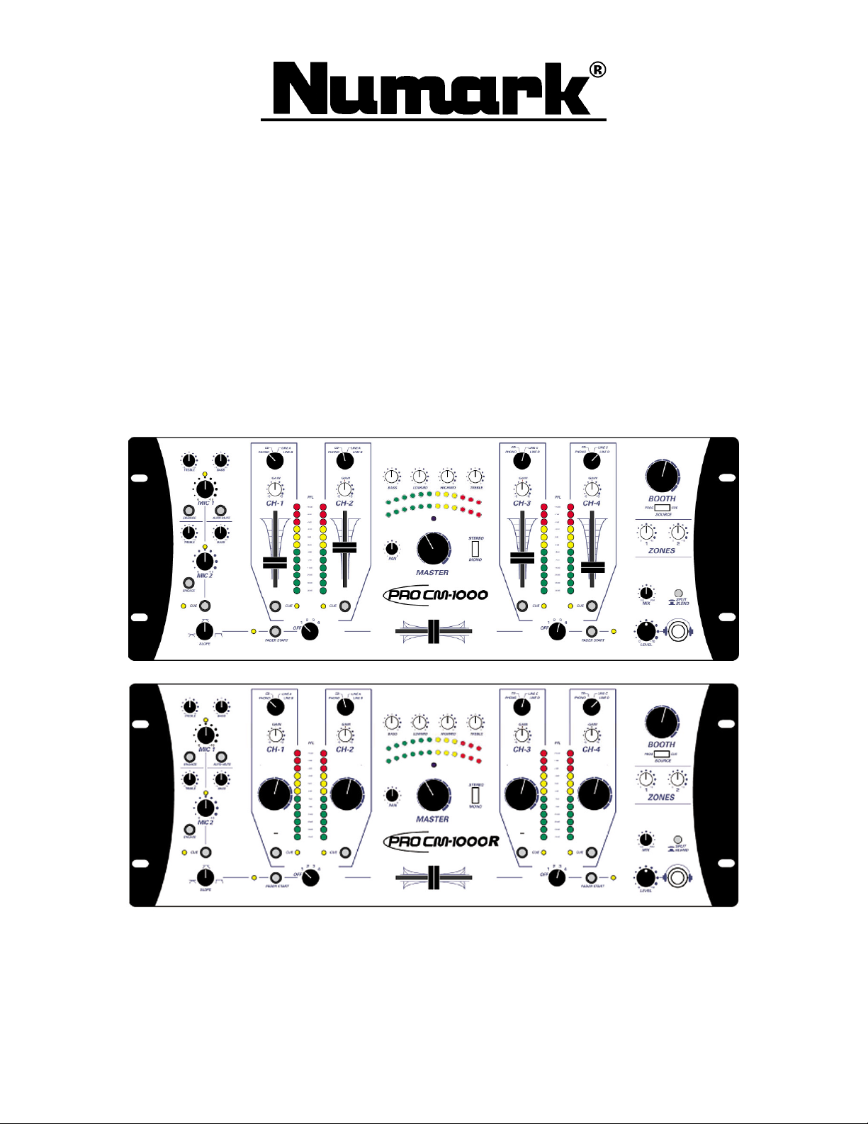
CM1000
CM1000
CM1000CM1000
CM1000R
CM1000R
CM1000RCM1000R
PROFESSIONAL CLUB MIXER
Owner’s Manual
Page 2

CM1000/CM1000R
©2000 Industries http://www.numark.com
- The Leader in DJ Technology
©2000 Industries - 2 - http://www.numark.com
Page 3
CM1000
Safety Information
SAFETY INSTRUCTIONS
a) Read Instructions - All the safety and operating
instructions should be read before this product is
connected and used.
b) Retain Instructions - The safety and operating instructions
should be kept for future reference.
c) Heed Warnings - All warnings on this product and in
these operating instructions should be followed.
d) Follow Instructions - All operating and other instructions
should be followed.
e) Water and Moisture -
This product should be
kept away from direct
contact with liquids.
f) Heat - Avoid placing this
product to close to any high heat sources such as radiators.
g) Ventilation - The appliance should be situated so that it’s
location or position does not interfere with it’s proper
ventilation. For example, the appliance should not be
situated on a bed, sofa, rug, or similar surface that may
block the ventilation opening;
or, placed in a builtinstallation, such as bookcase
or cabinet that may impede
the flow of air through the
ventilation openings.
h) Power Sources - This product should be connected to a
power supply only of the type described in these operating
instructions, or as marked on the unit.
i) Power Cord Protection - Power supply cords should be
routed so that they are not likely to be walked upon or
pinched by items placed on or against them. When
removing the cord from a power outlet be sure to remove
it by holding the
plug attachment
and not by pulling
on the cord.
j) Object and Liquid Entry - Take care that objects do not
fall into and that liquids are not spilled into the inside of
the mixer.
k) Cleaning – The appliance should be cleaned only as
recommended by the manufacturer.
l)
Non-use Periods – The power cord of the appliance
should be unplugged from the outlet when left unused for
long periods of time.
m) Damage Requiring Service - Only qualified personnel
should service this product.
If you have any questions
about service please contact
Numark at the number(s)
shown on the back cover of
this manual.
n) Grounding or Polarization - Precautions should be taken
so that the grounding or polarization means built into the
CD player is not defeated.
o) Internal/External Voltage Selectors - Internal or external
voltage selector switches, if any, should only be reset and
re-equipped with a proper plug for alternative voltage by a
qualified service technician. Do not attempt to alter this
yourself.
WARNING: To reduce the risk of fire or electrical shock, do
not expose this appliance to rain or moisture. Electrical
equipment should NEVER be kept or stored in damp
environments.
- The Leader in DJ Technology
©2000 Industries - 3 - http://www.numark.com
Page 4

Page 5

CM1000/CM1000R
VERY IMPORTANT
Please read this entire manual before connecting this unit to your system
For optimum performance:
•
The crossfader is a user replaceable item and subject to wear. Excessive force can wear out the fader quickly. This is not a
warranted item.
•
Never use spray cleaners on the slide controls. Residues cause excessive dirt build-up and this will void your warranty. In normal
use slide controls can last for many years. If they malfunction (usually because of a dirty or dusty environment) consult a
professional technician.
•
Always make sure that AC power is OFF while making any connections.
•
Use appropriate cables throughout your system. Do not use excessively long cables (i.e. over 50ft/14m) Be sure plugs and jacks
are tightly mated. Loose connections can cause hum, noise or intermittents that could easily damage your speakers. Make the input
and output connections with readily available low-capacitance stereo cables. Quality cable makes a big difference in audio fidelity
and punch. See your Numark dealer or an electronics or audio specialist store if you are not sure which cables to get.
•
Never attempt to make any adjustments or repairs other than those described in this manual. Take the unit to your dealer or to an
authorized Numark Service Center.
•
ALWAYS remember: “TURN AMPS ON LAST AND OFF FIRST”. Begin with master faders or volume controls on minimum
and the amplifier gain/input control(s) down. Wait 8 to 10 seconds before turning up the volume. This prevents transients which
may cause severe speaker damage.
•
Use restraint when operating controls. Try to move them slowly. Rapid adjustments could damage speakers due to amplifier
clipping.
•
Avoid amplifier “clipping” at all costs: this occurs when the red LEDs (usually on the front panel of most professional power
amplifiers) start flashing. “Clipping” is when the power amplifier is distorting and working beyond it’s limits. Amplifier distortion
is THE major cause of speaker failure.
•
To prevent fire or shock hazard, do not expose the unit to rain or moisture. Never place cans of beer, soda, glasses of water or
anything wet on top of the unit!
Product Registration
Please record the serial number of your unit as shown on the back of the chassis as well as the name of the
dealer from whom you purchased the unit. Retain this information and your original purchase receipt for
your records. Please return the enclosed warranty card to register your unit with us.
MODEL: __________________________ PURCHASED FROM:_________________________
SERIAL NUMBER:__________________ DATE OF PURCHASE:________________________
- The Leader in DJ Technology
©2000 Industries - 5 - http://www.numark.com
Page 6

CM1000/CM1000R
CM1000/CM1000R
CM1000/CM1000R
CM1000/CM1000RCM1000/CM1000R
PROFESSIONAL CLUB MIXER
CONGRATULATIONS!
You have just purchased the most versatile professional club mixer available today,
designed to accommodate both the professional installation market and club DJs alike. Its unique and comprehensive set of
features makes it a desired choice for professional audio needs. The CM1000 is manufactured utilizing the highest quality audio
components and advanced audio circuitry. Featuring inputs for 12 line, 4 phono, and 2 mics with EQ and auto ducking, fader
start, along with a complete compliment of balanced outputs, the CM1000 provides users with total control. This mixer also
boasts special contractor features such as EQ defeat, master gain reduction, VU adjustment, phantom power, and a ground lift.
’s CM1000 and CM1000R model with rotary controls, will prove to be the mixer of choice in professional club
settings.
Thank you for purchasing NUMARK products!
FEATURES:
Inputs:
• 12 line, 4 phono, 2 mic
• Individual channel PFL meter and gain controls
• 2 Mic inputs with individual EQ
• Mic 1 contains auto-mute, process control, and phantom power switch option
• 4 individual phono ground lugs
Crossfader:
• High quality ALPs™ VCA replaceable crossfader
• Selectable 4 channel fader crossfader start
• Slope adjustment
’s CM1000. This mixer is
Outputs:
• Master balanced/unbalanced with Panning, Stereo/mono switch, and rear panel Master Gain
reduction control
• Zone 1 balanced/unbalanced, Zone 2
• Light/Mono with rear panel level control
• Record with and without mic
• Booth balanced/unbalanced with cue or program output select
• Headphone with Split/blend, program mix, and volume control
• 4 – band master EQ with +/-6 or 12dB range adjustment and defeat
• Latching RJ11 connector and ground lift
- The Leader in DJ Technology
©2000 Industries - 6 - http://www.numark.com
Page 7

TABLE OF CONTENTS
CM1000/CM1000R
Safety Measures
Important Information
Registration
Introduction
Description of the Features
2
3
3
4
6
Quick Setup Diagram
Block Diagram
Specifications
Warranty
9
10
11
12
- The Leader in DJ Technology
©2000 Industries - 7 - http://www.numark.com
Page 8

CM1000/CM1000R
FRONT PANEL FEATURES
4
2
8
1
7
5
6
3
20
22
26
21
23
24
14
15
1
25
10
11
9
19
1617 18
INPUTS
1. Input faders - control individual source levels in
the mix.
2. Pre-fader Gain Controls – adjust the pre-fader
volume for cleaner sound.
3. PFL Meter - used to adjust the PFL levels,
accurately match channel levels with the Pre-fader
gain controls before mixing them together. The idea
is to properly match PFL inputs. You should not
attempt to match the input with the stereo output
meter!
4. Channel Input Selector – determines what input
source is controlled by the channel.
MICROPHONE
5. Mic Gain Controls – Controls the volume of the
microphones
6. Mic Activation Switch – turns microphone input on
and off.
7. Treble and Bass Controls – for fine-tuning the tone
of your voice on both mics through the sound
system. The controls are detented for setting tone
"flat".
8. Auto-Talkover Switch- reduces the input level of
Channels 1-4. This works with the auto talk-over
sensitivity adjustment on the rear panel. Talkover is
very useful for making announcements without
adjusting any levels.
13
12
HEADPHONE CUEING
9. Channel Cue Assign - are used to route Pre Fader
Level (PFL) channel audio to the Monitor Section.
The channel faders do not control the Cue volume.
10. Split/Blend Cue – controls how PFL and Program
audio are sent to your headphones. In split mode,
the PFL audio can be heard in your left ear and
PGM audio can be heard in your right ear. In blend
mode, both PFL and PGM can be heard in both ears.
11. Headphone Mix - controls the mix of PFL and
PGM signals to your headphones. When the slider
is moved to the left, all you will hear is the cue
source. When the slider is all the way to the right,
you will hear what is playing through the master
output. By blending, beats can be matched exactly
and segues can be smooth when a song is cued.
12. Headphone Level – adjusts cue volume.
13. Headphone output – ¼” jack for your headphones.
14. Booth Output – controls the volume of booth
monitor speaker if attached. Can also be used as an
additional zone or lighting control
15. Booth source switch – routes either program audio
or cue selected audio to the booth output. In “CUE”
mode the output audio matches selections made for
the headphones. For instance, in split cue mode you
would here cued audio in the left booth speaker and
program audio in the right booth speaker. Balance
would be controlled by the blend control. In this
way mixing can be done without headphones.
- The Leader in DJ Technology
©2000 Industries - 8 - http://www.numark.com
Page 9

CROSSFADER
16. Replaceable Crossfader - achieves clean segues
between the two input channels selected by the
Crossfader Assign.
In this example "Hard left" selects Channel 1 and
"Hard right" selects Channel 4. With the crossfader
centered, both assigned channels are live. Use the
crossfader for fast and seamless segues from one
selected channel to the other.
The crossfader is replaceable in case of
Note:
failure. Simply remove all knobs from the facepanel
and unscrew the 5 screws that hold it in place.
Then remove the 2 fader screws that hold the
crossfader to the subchassis, lift it out and
disconnect its cable. Re-attach the new crossfader
and replace the faceplate and knobs back onto the
unit - you’re back in business!
17. Crossfader Slope – determines how quickly the
audio from the opposing side of the crossfader
activates. A tight curve (hard right) turns on the
opposing audio signal with very little crossfader
movement. A loose curve (hard left) makes very
long and smooth segues in transition.
18. Crossfader Assign Knob - determines which input
channel will be heard when the crossfader is moved
towards the knob and which channel is fader start.
All channels not assigned will remain active.
Note:
19. Fader Start – activates the crossfader to send play
and cue commands to your auto-start Numark CD
player or other popular brand using pulse
technology. For fader start, attach your mixer to a
remote start CD player using industry standard
1/8”(3.5mm) cables. When you move the crossfader
toward the active channel, the attached CD player
will start. When it is moved away, that side will cue
(similar to pressing the cue button).
CM1000/CM1000R
OUTPUTS
20. 4-Band EQ control – adjusts the master output
according the setting on the rear panel. When the
unit is set for +/- 6 or 12dB the unit will increase or
decrease the frequency area adjusted.
21. Master Fader – to control the overall output level.
22. Panning – adjusts the balance of right and left
audio.
23. Stereo/Mono toggle - adjusts the Master output for
stereo or mono operation.
24. Stereo Auto Peak Hold Level Indicator- quickly
and accurately tracks level of audio sent to it by the
meter assign. The red LEDs for +3dB, +5dB and
+8dB hold program peaks for a second or two. With
peak metering, it's OK to be "in the red" as long as
+5dB or +8dB aren't constantly lit. When using as a
master output meter, set the crossover, equalizer
and power amp inputs to avoid distortion at each
step in the audio chain. Proper attention to the peak
meter results in the punchiest possible sound
without audible distortion. When used to adjust
the PFL levels, accurately match channel levels
with the Pre-fader gain controls before mixing them
together. The idea is to properly match PFL inputs,
not the input with the stereo output meter!
25. Zone Faders - controls speaker volume for a remote
zone or booth monitors.
NOTE:
audio to a lighting controller or to lights that are
sound activated.
26. Power Indication LED – indicates when power is
applied to the unit and the rear panel power switch
is on.
This can also be used to supply line level
- The Leader in DJ Technology
©2000 Industries - 9 - http://www.numark.com
Page 10

CM1000/CM1000R
REAR PANEL FEATURES
2426 25
3
2
1
18
20
19
18
20
21
17
17
22
23
16
15
10
8
7
6
14
5
4
4
9
11
12
13
1. Power Switch – to turn unit on after you have turned on
all input devices and before you turn on any devices
attached to the output.
2. Power Supply Input - to plug your power adapter in
before switching on power. See safety precautions on
page 3 for proper treatment of power.
3. Ground Lift – to separate chassis and power grounding in
case of signal hum. Move this to the ungrounded position
if system hum occurs to try and resolve any problems.
4. Line Inputs - to connect stereo audio from HiFi VCRs,
cassette and reel-to-reel tape decks, DAT machines, CD
players, laser discs, tuners, even synthesizers or other
mixing consoles.
NOTE: Plug mono audio sources into both Left and Right
inputs using a “Y" cable connector.
5. Phono/Auxiliary Inputs – to plug your turntables or line
device. Select the AUX/PHONO switch (6) to the desired
input.
6. Phono/Auxiliary switch – select the appropriate position
for your input device. With phono selected the input
signal is fed directly to the PRO SM-1's high-quality
RIAA phono pre-amplifiers so use this input only for
turntables. Line level sources will overload the sensitive
phono pre-amps. Switch this over to the AUX position
for line devices such as CD players and Tape decks.
7. Ground lug - use these connections with your turntables’
grounding cable to avoid signal hum.
8. Fader Start Jacks – for connecting fader start devices
such as CD players.
9. Mic 1 input – for connecting either XLR or ¼” balanced
microphone cables
10. Phantom power switch – to add 15V power for some
specialized microphones. Leave this in the off position
unless needed. The on position could potentially damage
microphones not designed to be powered.
11. Mic Process Send/Return Loop– attach this to any
devices you would like to process the microphone with.
The jack is wired TRS where tip is neutral, ring is send,
and sleeve is return.
12. Auto mute level – to set the level of audio reduction with
the auto-talk over is activated on the front panel.
13. Auto mute sensitivity- determines the mic loudness at
which auto muting is activated.
14. Mic 2 input – for ¼” mic cables.
15. EQ sensitivity – for determining how much the front
panel EQ can adjust the sound. The off position will
disable the EQ from modifying the sound.
16. Process Send/Return – for processing the program
material external processors such as EQs and effects units.
17. House/Master Outputs – controlled by the master fader.
The XLR Balanced Outputs are the best choice to use in
large systems. Power transformers and other devices
which cause magnetic fields can induce hum in audio
cables. This can be best resolved by using balanced lines
where inputs and outputs permit. Balanced lines are also
the most effective means of reducing or eliminating RF or
radio frequency" interference.
18. Booth Outputs – controlled by the booth fader
19. Booth Stereo/Mono switch- for use in single monitor
speaker situations
20. Zone 1 output - controlled by Zone 1 level control for
additional rooms or systems
21. Zone 2 output – controlled by Zone 2 level control for
additional rooms or systems
22. Record output with mic – to attached your tape deck and
record music with mic announcements
23. Record output without mic – to record just the music
without mic activity.
24. Light output – separately gain adjusted mono program
output to drive lighting system or sub woofers
25. Master Gain Reduction – adjusts the final output level
voltage for the balanced main outputs. This is factory
preset to current standards.
26. VU Meter adjust – should be adjusted so the front panel
output display indicates the optimum audio level to be
sent to the main sound system. This is factory preset to
typical levels.
- The Leader in DJ Technology
©2000 Industries - 10 - http://www.numark.com
Page 11

CM1000/CM1000R
QUICK SETUP DIAGRAM
Study this setup diagram. Make sure all faders are at "zero" and all devices are off. First, connect all
input sources and processors. Next, connect your microphone and monitor headphones. Finally, connect the
stereo outputs to the power amplifier(s) and/or audio receivers such as tape decks. Plug your mixer into AC
power. Now you are ready to switch everything on. IMPORTANT: Always switch on your audio input sources
such as turntables or CD players first, then your mixer, and finally any amplifiers. When turning off, always
reverse this operation by turning off amplifiers, then your mixer, and then input devices.
Light Control
Booth
- The Leader in DJ Technology
©2000 Industries - 11 - http://www.numark.com
Page 12

CM1000/CM1000R
BLOCK DIAGRAM
- The Leader in DJ Technology
©2000 Industries - 12 - http://www.numark.com
Page 13

SPECIFICATIONS
INPUTS:
Line: 10kohm input impedance
Mic: 10kohm input impedance unbalanced
Phono: 47kohm input impedance
OUTPUTS:
Line: 9V rms max
Headphone Amp: 0.5 watt into 47ohm
Distortion: less than 0.01%
SIGNAL TO NOISE RATIOS* (vs. maximum output):
Line: Better than 96 dB
Mic: Better than 78 dB
Phono: Better than 87 dB
CM1000/CM1000R
175mV rms sensitivity (for 1.22V output)
3mV rms sensitivity (for 1.22V output)
85mV rms max input
Phantom power: +15V
1.4mV rms sensitivity @ 1 KHz (for 1.22V output)
*JIS - weighted
FREQUENCY RESPONSE:
Line: 20 Hz- 22k Hz ±0.5 dB
Line: 20 Hz- 20k Hz ±0.5 dB
Phono: ±1 dB except for controlled attenuation of -3 dB
@ 20 Hz to reduce rumble and feedback
EQUALIZER:
Bass: +/-6,12dB @
Low Middle: +/-6,12dB @
Middle: +/-6,12dB @
Treble: +/-6,12dB @
POWER CONSUMPTION:
21.6 Watt typical
28.8 Watt with full headphone output
DIMENSIONS:
WEIGHT:
kgs, lbs
- The Leader in DJ Technology
©2000 Industries - 13 - http://www.numark.com
Page 14

Professional Disc Jockey Products
LIMITED PRODUCT WARRANTY
What is covered and for how long?
1. NUMARK INDUSTRIES LCC ("NUMARK") warrants to the original purchaser that NUMARK products; including but not limited to DJ mixers, amplifiers, CD players, CD Mix
Stations, turntables, preamplifiers, beatkeepers, equalizers, microphones, headphones, cartridges, and all other accessories; are to be free from defects in material and
workmanship under normal use and service for the period commencing upon the date of purchase from an authorized NUMARK dealer for a period of (1) Year.
What is not covered? This Limited Warranty is conditioned upon proper use of the product by the purchaser.
2. This Limited Warranty does not cover: (a) defects or damage resulting from accident, misuse, abuse, neglect, unusual physical or electrical stress, modification of any part of the
product, or cosmetic damage; (b) equipment that has the serial number removed or made illegible; (c) all plastic surfaces and other externally exposed parts that are scratched or
damaged due to normal use; (d) defects or damage from improper testing, operation, maintenance, installation, adjustment, or service of the mixers; (e) crossfaders.
3. What are NUMARK'S obligations? During the applicable warranty period, NUMARK will repair or replace, at NUMARK'S sole discretion, without charge to the purchaser, any
defective component part of the mixer. To obtain service under this Limited Warranty, purchaser must first contact NUMARK and obtain a return authorization number ("RA#").
Purchaser must then return the mixer to NUMARK in an adequate container for shipping, accompanied by purchaser's sales receipt or comparable proof of sale showing the date
of purchase, the serial number of the product, and the seller's name and address. To obtain an RA# and assistance on where to return the mixer, contact NUMARK customer
service at 401-295 9000. Upon receipt, NUMARK will repair or replace the defective products. NUMARK may, at NUMARK'S sole discretion, use rebuilt, reconditioned, or new
parts or components when repairing any product or replace a product with a rebuilt, reconditioned or new product. Repaired mixers will be warranted for a period equal to the
remainder of the original Limited Warranty on the original mixer or for (90) days, whichever is longer. All replaced parts, components, boards and equipment become the property
of NUMARK. If NUMARK determines that any mixer is not covered by this Limited Warranty, purchaser must pay all parts, shipping, and labor charges for the repair or return of
such mixer.
4. What are the limits on NUMARK'S liabilities? THE WARRANTIES GIVEN IN THIS LIMITED WARRANTY, TOGETHER WITH ANY IMPLIED WARRANTIES COVERING
NUMARK MIXERS, INCLUDING WITHOUT LIMITATION ANY WARRANTIES OF MERCHANTABILITY OR FITNESS FOR A PARTICULAR PURPOSE, ARE LIMITED TO THE
DURATION OF THIS LIMITED WARRANTY. EXCEPT TO THE EXTENT PROHIBITED BY APPLICABLE LAW, NUMARK SHALL NOT BE LIABLE FOR ANY SPECIAL,
INCIDENTAL, CONSEQUENTIAL, INDIRECT OR SIMILAR DAMAGES, LOSS OF PROFITS, DAMAGES TO PURCHASER'S PROPERTY, OR INJURY TO PURCHASER OR
OTHERS ARISING OUT OF THE USE, MISUSE OR INABILITY TO USE ANY NUMARK MIXER, BREACH OF WARRANTY, OR NEGLIGENCE, INCLUDING BUT NOT
LIMITED TO NUMARK'S OWN NEGLIGENCE, EVEN IF NUMARK OR ITS AGENT HAS BEEN ADVISED OF SUCH DAMAGES, OR FOR ANY CLAIM BROUGHT AGAINST
PURCHASER BY ANY OTHER PARTY. THIS LIMITED WARRANTY IS THE COMPLETE WARRANTY FOR NUMARK'S MIXERS, AND IS GIVEN IN LIEU OF ALL OTHER
EXPRESS WARRANTIES. THIS LIMITED WARRANTY SHALL NOT EXTEND TO ANYONE OTHER THAN THE ORIGINAL PURCHASER OF THIS PRODUCT AND STATES
PURCHASER'S EXCLUSIVE REMEDY. IF ANY PORTION OF THIS LIMITED WARRANTY IS ILLEGAL OR UNENFORCEABLE BY REASON OF ANY LAW, SUCH PARTIAL
ILLEGALITY OR UNENFORCEABILTY SHALL NOT AFFECT THE ENFORCEABILITY OF THE REMAINDER OF THIS LIMITED WARRANTY WHICH PURCHASER
ACKNOWLEDGES IS AND WILL ALWAYS BE CONSTRUED TO BE LIMITED BY ITS TERMS OR AS LIMITED AS THE LAW PERMITS.
5. This Limited Warranty allocates risk of product failure between purchaser and NUMARK, and NUMARK'S product pricing reflects this allocation of risk and the limitations of liability
contained in this Limited Warranty. The agents, employees, distributors, and dealers of NUMARK are not authorized to make modifications to this Limited Warranty, or make
additional warranties binding on NUMARK. Accordingly, additional statements such as dealer advertising or presentation, whether oral or written, do not constitute warranties by
NUMARK and should not be relied upon.
6. How does state law apply to this warranty? SOME STATES DO NOT ALLOW THE EXCLUSION OR LIMITATIONS OF INCIDENTAL OR CONSEQUENTIAL DAMAGES OR
HOW LONG AN IMPLIED WARRANTY LASTS, SO THE ABOVE LIMITATIONS OR EXCLUSIONS MAY NOT APPLY TO PURCHASER.
7.
This Limited Warranty gives you specific legal rights. You may also have other rights, which vary from one jurisdiction to another.
RETURN INFORMATION
a) A Return Authorization number must be obtained from Numark through the address or phone numbers below.
b) A copy of the original sales receipt must also be included for the equipment to be repaired under warranty.
c) The faulty equipment must be packed in its original packaging.
d) One additional outer layer of packaging must be included to ensure product safety. Failure to do so may inadequately protect the equipment in transit and, therefore,
jeopardize the customer’s warranty.
e) Numark will not accept COD shipments and no call tags will be issued for merchandise return.
f) Numark will not return repaired merchandise to customers by priority service, unless by written request at the customer’s cost. Requests must be submitted in writing
with merchandise returned.
g) The defective Numark equipment should be sent, FREIGHT PREPAID with Return Authorization number clearly printed on the outer packaging and original sales
receipt enclosed to:
INDUSTRIES
Attention: Service Department
11 Helmsman Avenue
North Kingstown, RI 02852 USA
Phone: +1 (401) 295-9000
Fax:: +1 (401) 295-5200
Web: www.numark.com
 Loading...