

Page 1
AXIS 2 CD Player with ANTI-SHOCK™
©2001 Industries http://www.numark.com
MANUAL
Page 2
AXIS 2
SAFETY INSTRUCTIONS
a) Read Instructions - All the safety and operating instructions should be read
before this product is connected and used.
b) Retain Instructions - The safety and operating instructions should be kept
for future reference.
c) Heed Warnings - All warnings on this product and in these operating
instructions should be followed.
d) Follow Instructions - All operating and other instructions should be followed.
e) Placement – place the unit in a clean dry location.
f) Water and Moisture - This product should be kept away from direct contact
with liquids. The apparatus shall not be exposed to dripping or splashing
and that no objects filled with liquids, such as vases, shall be placed on the
apparatus.
g) Temperature- Avoid placing this product to close to any high heat sources
such as radiators. Do not use this unit at temperatures below 41°F/5°C or
higher than 95°F/35°C.
h) Ventilation - The appliance should be situated so that it’s location or
position does not interfere with it’s proper ventilation. For example, the
appliance should not be situated on a bed, sofa, rug, or similar surface that
may block the ventilation opening; or, placed in a built-installation, such as
bookcase or cabinet that may impede the flow of air through the ventilation
openings.
i) Power Sources - This product should be connected to a power suppl y only
of the type described in these operating instructions, or as marked on the
unit.
j) Power Cord Protection - Power supply cords should be routed so that they
are not likely to be walked upon or pinched by items placed on or against
them. When removing the cord from a power outlet be sure to remove it by
holding the plug attachment and not by pulling on the cord.
k) Object and Liquid Entry - Take care that objects do not fall into and that
liquids are not spilled into the inside of the mixer.
l) Cleaning – The appliance should be cleaned only as recommended by the
manufacturer. Do not use chemical solvents to clean the unit.
m) Non-use Periods – The power cord of the appliance should be unplugged
from the outlet when left unused for long periods of time.
n) Damage Requiring Service - Only qualified personnel should service this
product. If you have any questions about service please contact Numark at
the number(s) shown on the back cover of this manual.
o) Grounding or Polarization - Precautions should be taken so that the
grounding or polarization means built into the CD player is not defeated.
p) Internal/External Voltage Selectors - Internal or external voltage selector
switches, if any, should only be reset and re-equipped with a proper plug
for alternative voltage by a qualified service technician. Do not attempt to
alter this yourself.
q) Carts and Stands -The appliance should be used only with a cart or stand
that is recommended by the manufacturer of the cart or stand. An
appliance and cart combination should be moved with care. Quick stops,
excessive force, and uneven surfaces may cause the appliance and cart
combination to overturn.
•
Disconnect power cord before servicing
•
Replace critical components
recommended equivalents
•
For AC line powered units - Before returning repaired unit to user,
use an ohmmeter to measure from both AC plug blades to all exposed
metallic parts. The resistance should be no more than 100,000ohms.
SERVICE INSTRUCTIONS
only with factory parts or
CAUTION: TO REDUCE THE RISK OF ELECTRIC SHOCK
DO NOT REMOVE ANY COVER. NO USER-
SERVICEABLE PARTS INSIDE. REFER SERVICING TO
QUALIFIED SERVICE PERSONNEL ONLY.
The lightning flash with arrowhead symbol within the
equilateral triangle is intended to alert the user to the
presence of un-insulated “dangerous voltage” within the
product’s enclosure that may be of sufficient magnitude to
constitute a risk of electric shock.
The exclamation point within the equilateral triangle is
intended to alert the user to the presence of important
operating and maintenance (servicing) instructions in
the literature accompanying this appliance.
CAUTION
FOR USA & CANADIAN MODELS ONLY
TO PREVENT ELECTRIC SHOCK DO NOT USE
THIS (POLARIZED) PLUG WITH AN
EXTENSION CORD, RECEPTACLE OR OTHER
OUTLET UNLESS THE BLADES CAN BE FULLY
INSERTED TO PREVENT BLADE EXPOSURE.
WARNING:
appliance to rain or moisture. Electrical equipment should NEVER be kept or
stored in damp environments.
NOTICE CONCERNING FCC REGULATIONS
This equipment generates and uses radio frequency energy and may cause
interference to radio and television reception if you do not operate it in strict
accordance with the procedures detailed in this OPERATING MANUAL.
This unit complies with Class B computing device rules in accordance with
the specifications in Sub-part J or Part 15 of the FCC Rules, which are
designed to provide reasonable protection against such interference in a
residential installation. There is no guarantee, however, that interference will
not occur in a particular installation. If the unit does cause interference to any
radio or television reception, try to reduce it by one or more of the following
means:
This note is in accordance with Section 15.838 of the FCC Rules.
This unit does not exceed the Class B limits for radio noise emission
from digital apparatus set out in the radio interference regulations of
the Canadian Department of Communications.
To reduce the risk of fire or electrical shock, do not expose this
a) Reposition the other unit and/or its antennae
b) Move this unit
c) Move this unit and the other unit(s) further apart
d) Plug this unit into a different AC outlet so that it is
on a different circuit from the other equipment.
DANGER: INVISIBLE LASER RADIATION WHEN OPEN AND INTERLOCK
FAILED OR DEFEATED. AVOID DIRECT EXPOSURE TO BEAM.
USE OF CONTROLS OR ADJUSTMENTS OTHER THAN THOSE SPECIFIED
HEREIN MAY RESULT IN HAZARDOUS RADIATION EXPOSURE
DOUBLE INSULATED - When servicing use only identical replacement parts
For 220-volt use in USA, use NEMA style 220-volt plug. For other countries use proper plug for local outlet.
©2001 Numark Industries
- The Leader in DJ Technology
- 2 -
http://www.numark.com
Page 3
®
AXIS 2
AXIS 2
AXIS 2AXIS 2
PROFESSIONAL TABLETOP
PROFESSIONAL TABLETOP
PROFESSIONAL TABLETOPPROFESSIONAL TABLETOP
CONGRATULATIONS...
You have just purchased a CD player designed specifically for the professional
DJ. This unit has been designed to provide CD mixing with the same ease and
creativity that you have enjoyed with records. Please take a few moments to
familiarize yourself with the AXIS 2 by reading the following information before
attempting to operate the unit.
Once again, congratulations and thank you for making the AXIS 2 your choice in
professional CD players.
CD PLAYER
CD PLAYER
CD PLAYERCD PLAYER
AXIS 2
FEATURES:
• Large interactive pitch wheel
adjustment
• Back lit buttons
• Fader/relay start
• Digital Output
CHECK TO BE SURE
THE FOLLOWING ITEMS ARE IN THIS BOX:
CD UNIT
IEC POWER CORD
FADER START CABLE
Please record the serial number of your unit as shown on the back of the chassis as well as the name of the dealer from whom you
purchased the unit. Retain this information and your original purchase receipt for your records. Please return the enclosed warranty
card to register your CD player with us.
• Frame search
• Auto cue
• +10 tracks skip search
•
Pitch display
OWNERS MANUAL (THIS BOOKLET)
RCA CONNECTING CABLES
MODEL: __________________________ PURCHASED FROM:_________________________
SERIAL NUMBER:___________________ DATE OF PURCHASE:________________________
©2001 Numark Industries
- The Leader in DJ Technology
- 3 -
http://www.numark.com
Page 4

AXIS 2
TABLE OF CONTENTS
Safety Instructions 2
Introduction and Registration 3
Set-up & Connections 5
Description of the Features
Top Panel 6
Front Panel 8
Rear Panel 8
Display 9
Basic Operation
Play, Pause and Cue Operations 10
Matching the Tempo 11
Beat Matching Using Pitch Bend 11
Relay and Fader Start 12
Example of Mixing 13
Before Switching off the Power 14
Troubleshooting Guide 14
Information and Specifications 15
Warranty 16
©2001 Numark Industries
- The Leader in DJ Technology
- 4 -
http://www.numark.com
Page 5
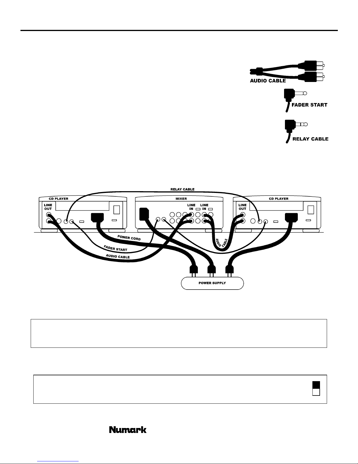
SETUP and CONNECTIONS
Typical connection with a mixer is illustrated below.
1. Find a level surface free of excessive vibration to place your equipment
2. Connect the line output connections using the supplied audio cable from the CD
Player to the line inputs of your mixer.
3. Connect Fader start cable. Attach your CD play to a similarly equipped DJ mixer.
(This connection can also be used with a remote switch)
If setting up 2 units, you can connect a relay cable between the units.
4.
(This cable is a standard 1/8” stereo – 1/8” stereo cable obtainable from you local music or
electronics store)
5. Connect IEC power cord to appropriate power source.
AXIS 2
DIGITAL OUTPUTS: This CD player is specially equipped with digital outputs. The format is type 2, form 1,
also known as S/PDIF (Sony/Phillips Digital Interface Format). When the digital output is used the variable
pitch slider and pitch bend buttons or pitch wheel should not be used.
Note: If digital information is allowed to change in pitch, other devices may not read the digital output properly.
LINE VOLTAGE SELECTION
1) The desired voltage may be set with the VOLTAGE SELECTOR switch on the rear panel of the unit.
2) Do not move the VOLTAGE SELECTOR switch with excessive force as this may cause damage.
3) If the VOLTAGE SELECTOR switch does not move smoothly contact a qualified serviceman.
©2001 Numark Industries
- The Leader in DJ Technology
- 5 -
115V
230V
http://www.numark.com
Page 6

AXIS 2
TOP PANEL FEATURES
©2001 Numark Industries
- The Leader in DJ Technology
- 6 -
http://www.numark.com
Page 7

AXIS 2
1. Open/Close: Press to load or eject the disc. The tray will not open if a disc is in play. The tray door will automatic close in 30
seconds if left open. This is to protect the tray from accidental damage while open
2. Single: toggles the unit to play back just one track at a time (single) or play continuously through all tracks and then start over
repeating the CD infinitely (continuous).
3. Time: switches the time modes on the display between elapsed playing time, remaining time on the track, and remaining time on
the total CD. When toggled to remaining time total the total number of remaining tracks will also show.
4. LCD DISPLAY -
5. Track Buttons: These buttons are used to select the track to be played. “+10” allows the user to quickly move through tracks on
the CD.
6. Search Buttons: Pressing these buttons create a rapid scan of the music to find a cue point.
7. Cue:
8. Play/Pause: Starts the music from the cue point or pauses it while in play. By pressing play after pause a new cue point will be
9. Jog Wheel:
10. Pitch Range: activates the pitch slider and adjusts the amount of control the pitch slider has on the overall speed of music.
11. Pitch Range LEDs:
12. Pitch Bend Buttons:
13. Pitch Slider: By moving the slider in the (+) direction the speed of the music permanently speeds up. By moving the slider in the (-
14. BPM - Tapping this button with the beat of the music indicates the current Beats Per Minute (BPM) in the display. The unit will
15.
Returns and pauses the music at the last set cue point. The cue point is where the music will begin when play is pressed.
The cue point is set as the initial start point on a track or can be moved when play is started at a different point. For instance, if
the music is paused, pressing play will set a new cue point. You can easily edit the cue point by turning the wheel during pause.
As you rotate the wheel the music will sound. By stopping the wheel and pressing play a new point is set. Alternately pressing the
PLAY button and the CUE button allows the CD to be played from the same position any number of times.
Note: Pressing cue 2 times plays music temporarily from this point until the button is released.
set
Cue Function: As explained under “CUE”, when the music is paused and you rotate the wheel, music will sound. By pressing play
a new cue point is set.
Pitch Bend Function: allows the user to temporarily change the speed of the music to align beats. When the beats of the music
of the CD you wish to match is fast compared to the tempo of the other music rotate the jog wheel counter clockwise (to the left).
When the CD is behind rotate the jog wheel clockwise (to the right). The pitch changes temporarily while the jog wheel is rotated.
The faster you rotate the wheel the more pitch is changed. Releasing the wheel results in a return to the original pitch.
Tapping the pitch will toggle slider between 8% and 16% pitch ranges. Holding the pitch for 3 seconds will deactivate the pitch
control.
the CD you wish to match is fast compared to the tempo of the other music press the (-). When the CD is behind press the (+).
The pitch changes temporarily while the (+) or (-) button is being pressed. The longer you hold the buttons the more pitch is
changed. Releasing the buttons results in a return to the original pitch.
) direction the speed of the music permanently slows down. To match the speeds of two CDs you can adjust the pitch. When the
tempo of the music of the CD you wish to match is slow compared to the tempo of the other music, move the slider to the (+) side
and match the speed. When faster, move the pitch slider to the (-) side. By making this adjustment the speeds will be matched
though the beats may not yet be aligned.
average your taps to determine the BPM so multiple taps is recommended.
Relay – Pressing this button on two units connected by the relay cable will cause the units to alternate play as one stops and the
other starts. If the units are set to single play mode then relay will alternate after each track. If the unit is set to continuous it will
relay after the entire CD is played.
Indicates all the functions, as they are occurring, with the CD.
indicate current pitch range. When both LEDs are off the pitch slider is not active
Allows the user to temporarily change the speed of the music to align beats. When the beats of the music of
©2001 Numark Industries
- The Leader in DJ Technology
- 7 -
http://www.numark.com
Page 8

AXIS 2
FRONT PANEL
16. CD Illumination Light – lights up the CD drawer and CD when open.
CD Drawer – Place your CDs you wish to play in here. This unit is designed to play commercially available CD and properly burned and finalized
17.
CDR and CDRW formats. Due to variances on the specification of certain CD burners and CDs some discs home made CDs may not play
properly.
REAR PANEL
18. Power Switch- Turn on and turn off the machine with this button. The unit should always be shut down with this button first before any external
power is removed. Typically it is recommended that the CD player is powered on before amplifiers and off after amplifiers to avoid an audio spike
to be sent through your equipment.
19. Voltage Selector - Set this switch to the voltage for your location.
20. IEC Power Plug Connector - Plug your supplied power cord in here.
21. RCA Audio Connectors - Connect your CD player to your mixer from this line level output.
22. Digital Output - The format is type 2, form 1, also known as S/PDIF (Sony/Phillips Digital Interface Format). In order to use the digital output you
should not use variable pitch slider and the pitch bend buttons. If you adjust the pitch, other devices may not read the digital output properly
because the sampling rate changes
23. Relay Connector- If you wish to use the relay function plug in your 3.5mm stereo control cables into here and then into your other unit. The cable
must be a stereo style plug for the units to work properly
24. Remote Start Connector – Use this connector to plug into your fader start compatible mixer or remote switch. This function is always active. To
use this connector for fader start, connect the supplied fader start cable to a fader start compatible mixer. Every time you move the crossfader on
the mixer over to the side that the unit is on, it will automatically start playing. When you move the fader away from that side, the unit will stop.
Moving the fader back to the unit side will start play again.
There are two potential modes associated with the switch PLAY-CUE and PLAY/PAUSE. The factory setting is PLAY-CUE mode. This means that
when the unit is remotely stopped it will go back to the cue point automatically. To change modes hold down the time button for 3 seconds and the
display will flash the play “
is, and resumes when the fader is brought back to the unit. To change modes back to PLAY-CUE hold down the time button for 3 seconds and the
display will flash the play “
25.
Remote Assignment Switch - Set this switch in the position for the method of remote start you will be using. Foot switches are often used for
creative mixing techniques and can be found in most music shops. Connector plugs are often ¼” and an adapter to 1/8” will be needed for
connection. There are also two types of footswitches that will work with this connector. The first is a typical, on/off pushbutton switch and are
generally used for switching channels on guitar amps. The second switch is a momentary footswitch and is usually used for keyboard sustain
pedals. If you are unsure of the style of switch you have, try each position until it works as desired.
• ON-OFF – for use with an ON-OFF switch.
•
MOMENTARY – for use with a momentary style of switch.
•
MIXER – for use with a fader start compatible DJ mixer
" and pause “
" and cue “
” icons. In PLAY/PAUSE mode, moving the crossfader away from the unit side pauses right where it
” icons in the display.
- The Leader in DJ Technology
©2001 Numark Industries
- 8 -
http://www.numark.com
Page 9
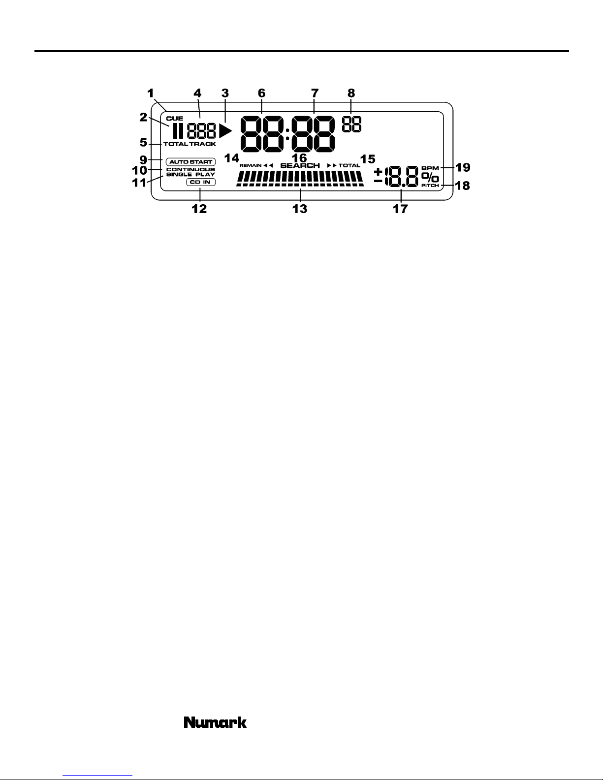
DISPLAY FEATURES
AXIS 2
1.
2. PAUSE (II)- Active when the unit is paused.
3. PLAY (>)- Active while the unit is actually playing a CD.
4. TRACK - Shows the track that the unit is playing.
5. TOTAL – indicates when total CD remaining tracks are displayed.
6.
7.
8. FRAMES - The CD Player breaks down a second into 75 frames for accurate cueing. This shows the frames elapsed or
9. AUTOSTART – will light when the unit is set to relay from CD unit to CD unit.
10. CONTINUOUS PLAY – Shows when the unit is set to play back the entire CD without stopping between tracks.
11. SINGLE PLAY- Shows when the unit is set to play just one track at a time.
12.
13. TIME BAR - Shows either track elapsed time, remaining track time, or remaining total time depending on the setting of the
14. (Remain) indicates when track remain time is displayed.
15. (Total) indicates when total CD remain time is displayed
16. SEARCH – indicates when the unit is searching through the music
17.
18. PITCH - is lit when pitch is being displayed
19.
Flashing when the unit is setting a cue point. Lit continuously when the unit is paused at a cue point.
CUE -
MINUTES -
SECONDS -
remaining depending on mode setting.
CD IN –
“time” button.
TIME MODE -
note: if both indications are not lit, the unit will be showing “elapsed” time
Numeric display
BPM – is lit when BPM is being displayed
Shows the minutes elapsed or remaining depending on mode setting.
Shows the seconds elapsed or remaining depending on mode setting.
indicates a standard CD is in the unit.
- indicating either current pitch or BPM
©2001 Numark Industries
- The Leader in DJ Technology
- 9 -
http://www.numark.com
Page 10

AXIS 2
DESCRIPTION OF THE PLAY/PAUSE AND CUE OPERATIONS
PLAY and CUE
Pressing the “PLAY/PAUSE” button starts the disc. Pressing the “CUE” button will reset the disc to the last place
where the disc was started. This is called the cue point. By alternately pressing the “PLAY/PAUSE” button and the
“CUE” button, the disc may be returned and played from the cue point any number of times. This function is called back
cue.
PLAY, PAUSE and CUE
When Play is paused and then started again, the return position for the back cue will be updated as the new cue
point
EDITING CUE POINT
When the jog wheel is turned while a cue point is set, a new cue point can be located. The CD player will
repeatedly play small parts of the CD as you move it to the desired position. By pressing “PLAY/PAUSE” then “CUE” you
can confirm that this new cue point is desirable.
- The Leader in DJ Technology
©2001 Numark Industries
- 10 -
http://www.numark.com
Page 11

AXIS 2
RELAY PLAY
This mode will be operational only when 2 units are connected via the supplied relay cable.
1. Insert CDs into both of the units.
2. Press the “RELAY” button on both units to activate.
3. We recommend putting both sides in SINGLE play mode
while learning this function.
4. Press play on the first unit. When that unit has finished play it will send a signal to the second unit to start play. You will see the
second unit start play and the first unit pause and cue to the beginning of the next track. When unit 2 has completed play unit 1 will
start.
Note: The play signal is sent at the end of specified play. If the unit is in SINGLE mode the play signal will start the second unit at the
end of the track. If the unit is in CONTINUOUS mode the play signal will be sent at the end of the full CD. Two CDs will play
continuously, alternating from unit to unit.
FADER START
Fader Start is achievable by attaching your CD player to a similarly equipped DJ mixer and setting the rear panel selection switch
to “mixer” mode.
1. Connect cables between the CD player and your DJ mixer.
2. Press the button or switch on your mixer into fader start mode to activate the fader start capability.
3. Typically if you move the crossfader toward the active channel, the attached CD player will activate. When it is moved away the
unit will cue or pause depending upon CD player setting.
To select start/stop mode hold the time button for 3 seconds.
If the display shows then the CD will pause when the crossfader is moved away.
If the display shows then the CD will CUE when the crossfader is moved away.
REMOTE SWITCH START
Remote switch start is achievable by attaching your CD player to a switch like a foot switch found in most music shops. Foot
switch connector plugs are often ¼” and an adapter to 1/8” will be needed for connection.
1. Connect the remote switch to your CD player.
2. Select the type of foot switch you will use. There are two types of footswitches that will work with this connector. The first is a
typical, ON-OFF pushbutton switch and are generally used for switching channels on guitar amps. The second switch is a
momentary footswitch and is usually used for keyboard sustain pedals. If you are unsure of the style of switch you have, try each
position until it works as desired.
3. Typically if you press the switch once, the attached CD player will activate. When it is pressed again the unit will cue or pause
depending upon CD player setting.
Note: You can also use a momentary switch in the ON-OFF switch position. In this case the unit will only play while the switch is
depressed. When the button is release it will either cue or pause depending upon mode.
©2001 Numark Industries
- The Leader in DJ Technology
- 11 -
http://www.numark.com
Page 12

AXIS 2
MATCHING THE BEATS PER MINUTE (BPM)
Match the tempo by monitoring the music of both PLAYER 1 and PLAYER 2 by ear and adjusting the pitch.
When the tempo of the music of the selected CD player is slow compared to the tempo of the other player, move the
slider to the “+” side and match the tempo. When faster, move the pitch slider to the “-“ side. The following description is
for the case of matching the pitch of PLAYER 2 to the pitch of the music being played on PLAYER 1.
Press PLAY/PAUSE to start PLAYER 1
PLAYER 1 is playing
Press PLAY/PAUSE to start PLAYER 2
Both CD players are playing discs.
Listen to PLAYER 2 in your headphones
When PLAYER 2 is slow
compared to PLAYER 1
speed up PLAYER 2
When PLAYER 2 is fast
compared to PLAYER 1
slow down PLAYER 2
MATCHING BEATS USING PITCH BEND
If you find the BPM’s (Beats Per Minute or Tempos) are the same, however, the drum beats are not matched you
will need to temporarily change the pitch. This description is for the case of matching the beat of PLAYER 2 to the beat of
the music being played on PLAYER 1. (This procedure can be done on either PLAYER).
After matching the BPM’s adjust the pitch temporarily as follows:
When PLAYER 2 is behind rotate the jog wheel
clockwise or press “+” to bend pitch faster
When PLAYER 2 is ahead rotate the jog wheel counter
clockwise or press “-“ to bend pitch slower.
or
The pitch changes automatically while the jog wheel is rotated. The faster you rotate the wheel the more you change.
Releasing the wheel results in a return to the original pitch. (So the BPM’s are once again the same)
©2001 Numark Industries
- The Leader in DJ Technology
- 12 -
or
http://www.numark.com
Page 13

EXAMPLE OF MIXING USING TWO CD PLAYERS
While playing a disc on PLAYER 1 load a disc into PLAYER 2 and select your next track, match its
pitch to the track playing on PLAYER1 and when you are ready use the crossfader on your mixer to fade from
PLAYER 1 to PLAYER 2.
AXIS 2
Load a disc in PLAYER 1
and select the track and
press PLAY.
Load a disc in PLAYER 2
and select the track then
play.
Set and edit a start cue
point on PLAYER 2
PLAYER 1
Load a disc and press the
OPEN/CLOSE button.
PLAYER 2
Load a disc and press the
OPEN/CLOSE button.
PLAYER 2
PLAYER 1
Select the track to be
played.
PLAYER 2
Select the track to be
played.
PLAYER 2
PLAYER 1
Press the PLAY button
PLAYER 2
Press the PLAY button
PLAYER 2
Check you new cue point
Do a MIX!
Press the Pause button of
PLAYER 2.
PLAYER 2
Listen with the monitor and
press the play button.
PLAYER 2
With a matching downbeat
from Player 1 press the
play button.
Rapidly search for a cue
point using the buttons
PLAYER 2
Press the cue button then
play to be sure of the set
cue point.
PLAYER 2
If you are beat mixing turn
on your Pitch adjust and
follow the directions for
beat matching.
Slowly set the right point
using the jog wheel
PLAYER 2
Set the player to the Cue
point by pressing Cue
MIXER
When you are happy with
you mix adjust you mixer
accordingly.
©2001 Numark Industries
- The Leader in DJ Technology
- 13 -
http://www.numark.com
Page 14

AXIS 2
BEFORE SWITCHING OFF THE POWER:
When you have finished using the CD player, be sure that the disc tray is closed with the “OPEN/CLOSE” button before
switching off the power.
DO NOT switch off the power when
the disc holder is open.
TROUBLESHOOTING:
Symptom Possible Cause Corrective Action
The power fails to switch on when the
POWER switch is set to on
Disc play does not start The disc is loaded upside down
No sound Improper output cable connections
Sound skips The CD player is subject to vibrations
Poor power plug connection at the AC
outlet or IEC Power cord loose from
rear of unit
The disc is too dirty
Improper amplifier operation
or physical shock
Switch off the power after the
disc holder has been closed
with the “OPEN/CLOSE” button
Insert the power plug firmly into the AC
outlet and make sure connection is
good in unit rear
Reload the disc with the label side up
Clean the disc
Connect the output cables correctly
Check amplifier setup
Change the installation location
Hum Loose cable connections Firmly connect all audio plugs
©2001 Numark Industries
The disc is too dirty
- The Leader in DJ Technology
- 14 -
Clean the disc
http://www.numark.com
Page 15

SPECIFICATIONS
TECHNICAL
Disc Type Standard Compact discs (12 cm & 8 cm)
Time Display Track Elapsed, Track Remain, or Total remain
Quantization 1 bit linear/Channel, 3 Beam Laser
Oversampling rate 8 Times
Sampling Frequency 44.1 kHz
Frequency response 20 Hz to 20 kHz
T.H.D. + NOISE Less Than 0.005%
S/N ratio (IHF-A) > 96 dB
Dynamic range > 94 dB
Output level 1.9 Volts R.M.S.
Start Time within 0.03 seconds
Pitch control range +/- 8 and 16% slider
Pitch bend +/-16% rotary and buttons
Digital Output type 2, form 1, S/PDIF (Sony/Phillips Digital Interface Format)
GENERAL
AXIS 2
Dimensions: 9.75” x 8.5” x 3.25” (247 x 216 x 82.5mm)
Weight: 5 lbs (2.3 kg)
Power Supply: 115/230V AC, 50/60Hz
Power Consumption: 15W
* Specifications are subject to change due to ongoing improvements
- The Leader in DJ Technology
©2000 Numark Industries
- 15 -
http://www.numark.com
Page 16

Professional Disc Jockey Products
LIMITED PRODUCT WARRANTY
1. What is covered and for how long? NUMARK INDUSTRIES LCC ("NUMARK") warrants to the original purchaser that NUMARK'S DJ Mixers, Amplifiers, CD
players, turntables, preamplifiers, beatkeepers, equalizers, microphones, headphones, and all other accessories are free from defects in material and
workmanship under normal use and service for the period commencing upon the date of purchase from an authorized NUMARK dealer and continuing for the
following period of time after that date for (1) Year.
2. What is not covered? This Limited Warranty is conditioned upon proper use of the product by the purchaser.
This Limited Warranty does not cover: (a) defects or damage resulting from accident, misuse, abuse, neglect, unusual physical or electrical stress, modification
of any part of the product, or cosmetic damage; (b) equipment that has the serial number removed or made illegible; (c) all plastic surfaces and other externally
exposed parts that are scratched or damaged due to normal use; (d) defects or damage from improper testing, operation, maintenance, installation, adjustment,
or service of the mixers; (e) crossfaders.
3. What are NUMARK'S obligations? During the applicable warranty period, NUMARK will repair or replace, at NUMARK'S sole discretion, without charge to the
purchaser, any defective component part of the mixer. To obtain service under this Limited Warranty, purchaser must first contact NUMARK and obtain a return
authorization number ("RA#"). Purchaser must then return the mixer to NUMARK in an adequate container for shipping, accompanied by purchaser's sales
receipt or comparable proof of sale showing the date of purchase, the serial number of the product, and the seller's name and address. To obtain an RA# and
assistance on where to return the mixer, contact NUMARK customer service at 401-295 9000. Upon receipt, NUMARK will repair or replace the defective
products. NUMARK may, at NUMARK'S sole discretion, use rebuilt, reconditioned, or new parts or components when repairing any product or replace a
product with a rebuilt, reconditioned or new product. Repaired mixers will be warranted for a period equal to the remainder of the original Limited Warranty on
the original mixer or for (90) days, whichever is longer. All replaced parts, components, boards and equipment become the property of NUMARK. If NUMARK
determines that any mixer is not covered by this Limited Warranty, purchaser must pay all parts, shipping, and labor charges for the repair or return of such
mixer.
4. What are the limits on NUMARK'S liabilities? THE WARRANTIES GIVEN IN THIS LIMITED WARRANTY, TOGETHER WITH ANY IMPLIED WARRANTIES
COVERING NUMARK MIXERS, INCLUDING WITHOUT LIMITATION ANY WARRANTIES OF MERCHANTABILITY OR FITNESS FOR A PARTICULAR
PURPOSE, ARE LIMITED TO THE DURATION OF THIS LIMITED WARRANTY. EXCEPT TO THE EXTENT PROHIBITED BY APPLICABLE LAW, NUMARK
SHALL NOT BE LIABLE FOR ANY SPECIAL, INCIDENTAL, CONSEQUENTIAL, INDIRECT OR SIMILAR DAMAGES, LOSS OF PROFITS, DAMAGES TO
PURCHASER'S PROPERTY, OR INJURY TO PURCHASER OR OTHERS ARISING OUT OF THE USE, MISUSE OR INABILITY TO USE ANY NUMARK
MIXER, BREACH OF WARRANTY, OR NEGLIGENCE, INCLUDING BUT NOT LIMITED TO NUMARK'S OWN NEGLIGENCE, EVEN IF NUMARK OR ITS
AGENT HAS BEEN ADVISED OF SUCH DAMAGES, OR FOR ANY CLAIM BROUGHT AGAINST PURCHASER BY ANY OTHER PARTY. THIS LIMITED
WARRANTY IS THE COMPLETE WARRANTY FOR NUMARK'S MIXERS, AND IS GIVEN IN LIEU OF ALL OTHER EXPRESS WARRANTIES. THIS
LIMITED WARRANTY SHALL NOT EXTEND TO ANYONE OTHER THAN THE ORIGINAL PURCHASER OF THIS PRODUCT AND STATES PURCHASER'S
EXCLUSIVE REMEDY. IF ANY PORTION OF THIS LIMITED WARRANTY IS ILLEGAL OR UNENFORCEABLE BY REASON OF ANY LAW, SUCH PARTIAL
ILLEGALITY OR UNENFORCEABILTY SHALL NOT AFFECT THE ENFORCEABILITY OF THE REMAINDER OF THIS LIMITED WARRANTY WHICH
PURCHASER ACKNOWLEDGES IS AND WILL ALWAYS BE CONSTRUED TO BE LIMITED BY ITS TERMS OR AS LIMITED AS THE LAW PERMITS.
This Limited Warranty allocates risk of product failure between purchaser and NUMARK, and NUMARK'S product pricing reflects this allocation of risk and the
limitations of liability contained in this Limited Warranty. The agents, employees, distributors, and dealers of NUMARK are not authorized to make modifications
to this Limited Warranty, or make additional warranties binding on NUMARK. Accordingly, additional statements such as dealer advertising or presentation,
whether oral or written, do not constitute warranties by NUMARK and should not be relied upon.
5. How does state law apply to this warranty? SOME STATES DO NOT ALLOW THE EXCLUSION OR LIMITATIONS OF INCIDENTAL OR CONSEQUENTIAL
DAMAGES OR HOW LONG AN IMPLIED WARRANTY LASTS, SO THE ABOVE LIMITATIONS OR EXCLUSIONS MAY NOT APPLY TO PURCHASER.
6. This Limited Warranty gives you specific legal rights. You may also have other rights, which vary from one jurisdiction to another.
RETURN INFORMATION
• A Return Authorization number must be obtained from Numark through the address or phone numbers below.
• A copy of the original sales receipt must also be included for the equipment to be repaired under warranty.
• The faulty equipment must be packed in its original packaging.
• One additional outer layer of packaging must be included to ensure product safety. Failure to do so may inadequately protect the equipment in transit
and, therefore, jeopardize the customer’s warranty.
• Numark will not accept COD shipments and no call tags will be issued for merchandise return.
• Numark will not return repaired merchandise to customers by priority service, unless by written request at the customer’s cost. Requests must be
submitted in writing with merchandise returned.
• The defective Numark equipment should be sent, FREIGHT PREPAID with Return Authorization number clearly printed on the outer packaging and
original sales receipt enclosed to:
INDUSTRIES
Attention: Service Department
11 Helmsman Avenue
North Kingstown, RI 02852 USA
Phone: +1 (401) 295-9000
Fax:: +1 (401) 295-5200
Web: www.numark.com
 Loading...