

Page 1

ESERV-M12T
Modbus Gateway
User Manual
Page 2

Table of Contents
TABL E OF C O N T E N T S
INTRODUCTION...................................................................................................................................... 1
About ESERV-M12T Modbus Gateways ................................................................................................................. 1
Modbus Gateway Manager Configuration Software .............................................................................................. 2
ESERV-M12-T MODBUS GATEWAY HARDWARE ........................................................................ 3
Package Checklist .................................................................................................................................................. 3
ESERV-M12T Modbus Gateways Enclosures and Mounting ................................................................................... 3
LED Indicators ........................................................................................................................................................ 4
Ethernet Link LED ....................................................................................................................................................... 4
Ready LED .................................................................................................................................................................. 4
Serial Port LEDs .......................................................................................................................................................... 4
Mode Switch .......................................................................................................................................................... 5
Ethernet Connector ............................................................................................................................................... 5
Serial Port Connectors ........................................................................................................................................... 6
Power Connector ................................................................................................................................................... 6
Mounting Hardware .............................................................................................................................................. 6
MODBUS GATEWAY SETUP AND CONNECTIONS ........................................................................ 8
Connecting the Power Supply ................................................................................................................................ 8
Connecting ESERV-M12T Modbus Gateways to Modbus networks ........................................................................ 8
Connecting the ESERV-M12T ..................................................................................................................................... 9
Connecting ESERV-M12T Modbus Gateways to a Network .................................................................................. 10
Network Connection (10BaseT/100BaseTX) ............................................................................................................ 10
ESERV-M12T Configuration Connections.............................................................................................................. 10
Configuring the ESERV-M12T Modbus Gateway via the Network Connection ....................................................... 10
Configuring the ESERV-M12T Modbus Gateway on Networks without a DHCP Server .......................................... 12
Configuring the ESERV-M12T Modbus Gateway via the Serial Port (Console Mode) ............................................. 15
i ESERV-M12T (Rev. 1210)
Page 3

Table of Contents
ESERV-M12T Modbus Gateway Operational Connections .................................................................................... 16
Using ESERV-M12T Modbus Gateways in Direct IP Mode ....................................................................................... 16
Initiating a Hardware Reset on the Modbus Gateway .......................................................................................... 17
Reloading Factory Defaults .................................................................................................................................. 17
DESCRIPTION, MODBUS GATEWAY PROPERTIES .................................................................... 18
Attached .............................................................................................................................................................. 18
Baud Rate ............................................................................................................................................................ 18
Character Timeout ............................................................................................................................................... 18
Configuration Files ............................................................................................................................................... 18
Data/Parity/Stop ................................................................................................................................................. 18
Default Gateway .................................................................................................................................................. 19
DHCP ................................................................................................................................................................... 19
Firmware Version ................................................................................................................................................ 19
Hardware Version ................................................................................................................................................ 19
ID Routing ............................................................................................................................................................ 19
IP Address ............................................................................................................................................................ 20
Link Status ........................................................................................................................................................... 20
MAC Address ....................................................................................................................................................... 20
Modbus Priority ................................................................................................................................................... 20
Modbus Serial Retries .......................................................................................................................................... 21
Modbus ASCII ...................................................................................................................................................... 21
Modbus Message Buffering ................................................................................................................................. 21
Modbus Message Timeout ................................................................................................................................... 21
Modbus RTU Message ......................................................................................................................................... 21
ii ESERV-M12T (Rev. 1210)
Page 4

Table of Contents
Modbus Serial Control ......................................................................................................................................... 21
Modbus TCP Message .......................................................................................................................................... 22
Model .................................................................................................................................................................. 22
Network Mode .................................................................................................................................................... 22
Network Protocols ............................................................................................................................................... 22
Password ............................................................................................................................................................. 23
Port# ID Remap.................................................................................................................................................... 23
Serial Interface Modes ......................................................................................................................................... 23
Modbus Gateway Name ...................................................................................................................................... 24
Gateway Serial Port Number ............................................................................................................................... 24
Subnet Mask ........................................................................................................................................................ 24
TCP (Transmission Control Protocol) .................................................................................................................... 25
UPGRADING THE MODBUS GATEWAY FIRMWARE ................................................................. 26
Downloading Firmware Files ................................................................................................................................ 26
Uploading the Firmware to the Modbus Gateway ............................................................................................... 27
DIAGNOSTICS ........................................................................................................................................ 28
Testing a Modbus Gateway Connection ............................................................................................................... 28
APPLICATION EXAMPLES ................................................................................................................. 30
Ethernet Master and Serial Slaves ....................................................................................................................... 30
Serial Masters, IP Slaves ...................................................................................................................................... 38
Identical Hard Coded Slaves ................................................................................................................................. 44
Identical Production Lines .................................................................................................................................... 45
Modbus ASCII/RTU Basics .................................................................................................................................... 46
iii ESERV-M12T (Rev. 1210)
Page 5

Table of Contents
Hints and Tips ...................................................................................................................................................... 46
APPENDICES .......................................................................................................................................... 47
Appendix A: Default Gateway Settings ................................................................................................................ 48
Appendix B: Product Specifications...................................................................................................................... 50
General Specifications ............................................................................................................................................. 51
Controls, Indicators and Connector Specifications .................................................................................................. 53
Serial Interface Specifications .................................................................................................................................. 54
Fiber Interface Specifications .................................................................................................................................. 55
Network Specifications ............................................................................................................................................ 56
Appendix C: Dimensional Diagrams ..................................................................................................................... 57
Appendix D: Connector Pinout ............................................................................................................................. 58
ESERV-M12T Serial Port Pinouts .............................................................................................................................. 58
Standard Ethernet Cable RJ-45 Pin-out ................................................................................................................... 59
GLOSSARY .............................................................................................................................................. 60
N-TRON LIMITED WARRANTY ........................................................................................................ 65
iv ESERV-M12T (Rev. 1210)
Page 6
Introduction ESERV-M12T Modbus Gateway
Model Number
Features
ESERV-M12T
2 PORT, TB, DIN, CU ETHERNET
ESERV-M12T-ST
2 PORT, TB, DIN, FIBER, MULTIMODE, ST
INTRODUCTI ON
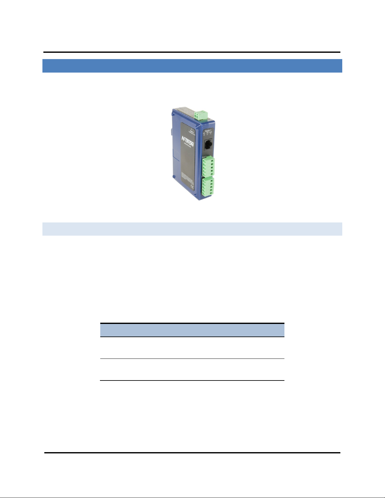
Thank you for purchasing an ESERV-M12T Modbus Gateway product! This product has been manufactured to the
highest standards of quality and performance to ensure your complete satisfaction.
Figure 1. An ESERV-M12T Modbus Gateway
ABOUT ESERV-M12T MODBUS GATEWAY S
ESERV-M12T Modbus Gateways connect Modbus networks (RS-232, RS-422 or RS-485) to Ethernet networks,
allowing the Modbus network to become a node on the network. The serial ports can be accessed over a
LAN/WAN using Direct IP Mode connections. ESERV-M12T Modbus Gateways feature 10BaseT or 100BaseTX
copper network media and fiber optic media options, depending on the model. ESERV-M12T Modbus Gateways
are built for use in industrial environments, featuring an IP30 approved slim line DIN rail mountable case. They
operate from a range of DC power supply voltages and feature pluggable terminal block power connectors. An
external power supply, sold separately, is required.
1 ESERV-M12T (Rev. 1210)
Page 7

Introduction ESERV-M12T Modbus Gateway
ESERV-M12T PRODUCT FEATURES
Two serial ports with pluggable terminal blocks, single Ethernet port)
Multi-interface serial ports
All ports are software selectable as RS-232, RS-422 or RS-485 2- and 4-wire
Configuration can be done via network or direct serial connection
Slim line DIN rail mountable case
Accepts DC power over a wide voltage range
10/100 Mbps Ethernet with Auto Selection, Auto MDI/MDIX
LAN and WAN Communications
TCP Client or Server operation - configurable
Firmware Upload for future revisions/upgrades
Software Support - Windows 2000/2003 Server/XP/Vista x32
Configuration of Ethernet and serial port settings using Modbus Gateway
Manager software
MODBUS GATEWAY MANAGER CONFIGURATION SOFTWARE
The Ethernet Modbus Gateway Manager configuration software enables you to find connected Modbus gateways,
configure them, upgrade Modbus gateway firmware, and save/load configuration files. It features a graphical user
interface (GUI) that is convenient and easy to use.
2 ESERV-M12T (Rev. 1210)
Page 8

Hardware ESERV-M12T Modbus Gateway
ESE R V- M12-T MODBUS GATEWAY HARDWARE
ESERV-M12T Modbus Gateways are enclosed in DIN rail mountable enclosures and feature LED indicators, power,
Ethernet and serial connectors and a recessed Mode switch.
PACKAGE CHECKLIST
ESERV-M12T Modbus Gateways are shipped with the following items included:
ESERV-M12T Modbus Gateway Module
Quick Start Guide
CD with User Manual, Quick Start Guide and firmware
ESERV-M12T MODBUS GATEWAYS ENCLOSURES AND MOUNT ING
Modules are DIN rail mountable.
Figure 2. Front View of an ESERV-M12T Modbus Gateway
3 ESERV-M12T (Rev. 1210)
Page 9

Hardware ESERV-M12T Modbus Gateway
LED INDICATORS
ESERV-M12T Modbus Gateways have three types of LED indicators: Ethernet Link LEDs, a Ready LED and
Serial Port LEDs.
Figure 3. Ready Ethernet Port LED
ETHERNET LINK LED
The Ethernet Link LED illuminates (green) if the Ethernet is connected. When the LED is blinking it indicates that
there is data traffic on the Ethernet link.
E1 is used to connect to the network.
READY LED
The Ready LED (green) blinks if the system is operating correctly, once per second in normal operating conditions,
or three times per second in reset, configuration mode, or when loading factory defaults. If the LED is off or steady,
it indicates the system is not operating correctly.
SERIAL PORT LEDS
ESERV-M12T Modbus Gateways feature two serial ports. Each serial port has an associated LED. Serial Port LEDs
blink (green) when data is being transmitted or received on the serial port. When the LED is On, it indicates the
serial port is open.
Figure 4. Serial Port LEDs
4 ESERV-M12T (Rev. 1210)
Page 10

Hardware ESERV-M12T Modbus Gateway
MODE SWITCH
A recessed momentary reset switch is located on the top of the enclosure. To activate the switch, insert a small
plastic tool through the hole in the enclosure and press lightly.
Figure 5. Mode Switch
The Mode switch can be used to:
Initiate a Hardware Reset
Enter Console Mode
Reload factory defaults
Note: Refer to Section 3. Modbus Gateway Setup and Connections for more information on using
the Mode switch.
ETHERNET CONNECTOR
Modbus gateway models using 10BaseT/100BaseTX network connections use an RJ45 receptacle. The Modbus
ESERV-M12T gateway is connected to a standard Ethernet network drop using a straight-through RJ45 (male)
Ethernet cable.
Fiber Optic Connectors
The ESERV-M12T-ST uses a multimode fiber optic network connection with ST style connectors.
Figure 6. ST Connector
5 ESERV-M12T (Rev. 1210)
Page 11
Hardware ESERV-M12T Modbus Gateway
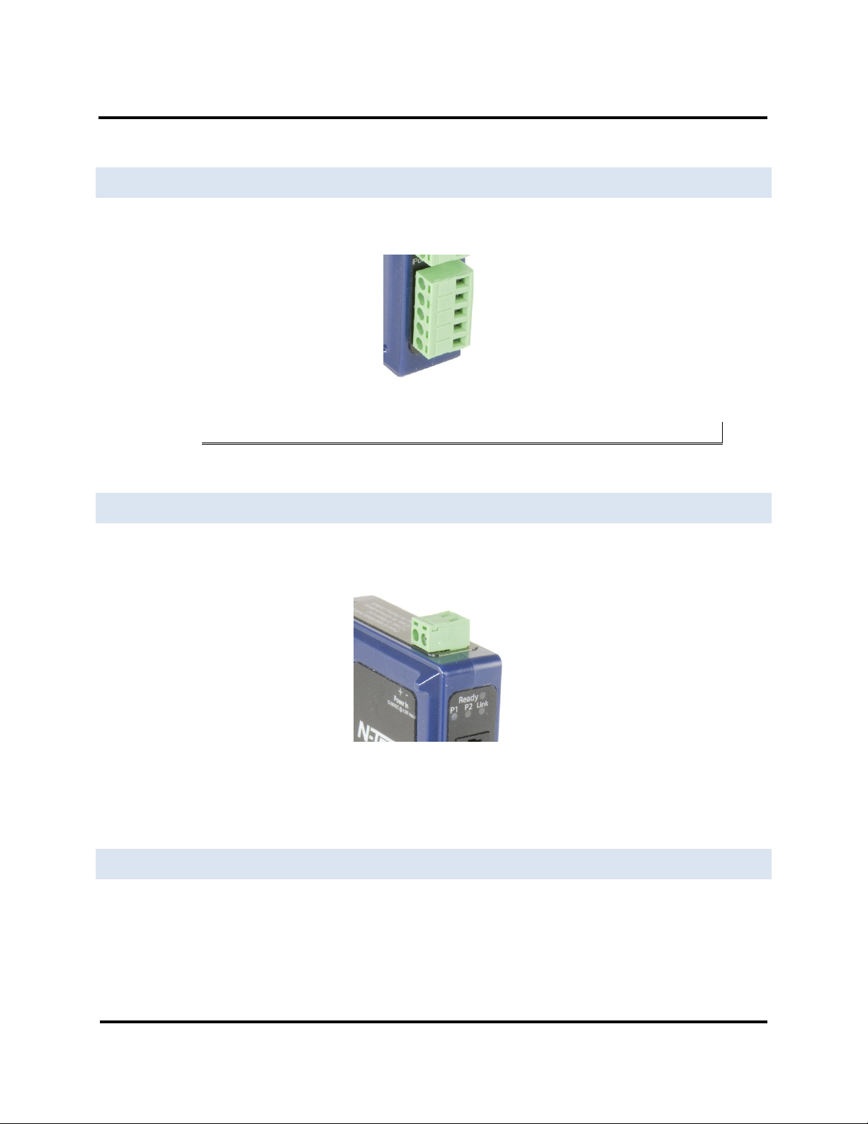
SERIAL PORT CONNECTO RS
The ESERV-M12T Modbus Gateway features two serial ports, both using five-position removable terminal blocks
for RS-232, RS-422 and RS-485 connections.
Figure 7. Five-Position Pluggable Terminal Block
Note: Refer to Appendix D for connection pin-outs.
POWER CONNECTOR
The power connector is a 2-position pluggable terminal block.
Figure 8. Power Connection
MOUNTING HARDWARE
ESERV-M12T modules can be DIN rail mounted. The DIN mounting clip and spring is included on each module.
6 ESERV-M12T (Rev. 1210)
Page 12

Hardware ESERV-M12T Modbus Gateway
Figure 9. ESERV-M12T DIN Clips
7 ESERV-M12T (Rev. 1210)
Page 13
Setup and Connections ESERV-M12T Modbus Gateway
MODB US G A T EWA Y SETUP AND CONNECTIONS
This section describes how to setup and connect ESERV-M12T Modbus Gateways.
Note: In this section devices to be connected to the Modbus gateway’s serial connection are simply
referred to as the “Modbus network”.
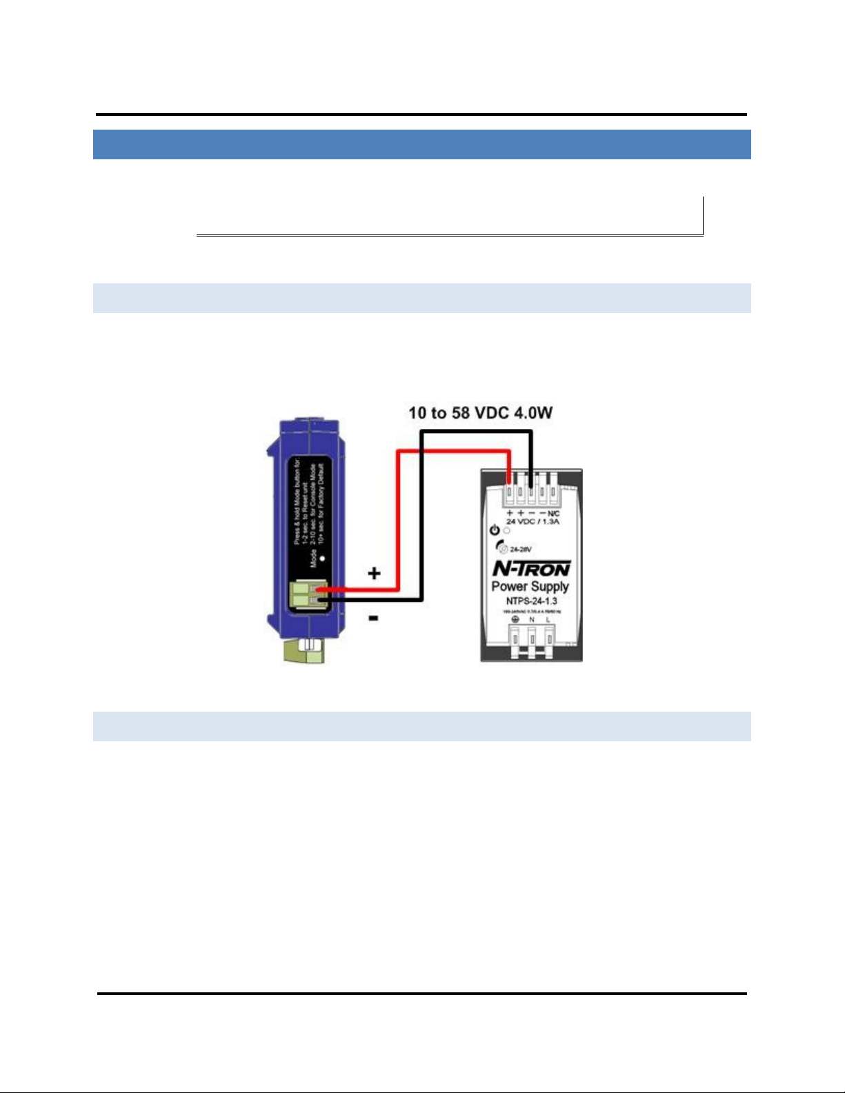
CONNECTING THE POWER SUPPLY
Connect a DC power supply to the power terminals on the top of the Modbus gateway. Polarity of the wires is
indicated on the label on the side of the Modbus gateway. Acceptable voltages are between 10 VDC and 58 VDC.
The power supply must be capable of supplying 4 Watts for ESERV-M12T units.
Figure 10. ESERV-M12T Power Connection
CONNECTING ESERV-M12T MODBUS GATEWAY S TO MODBUS NETWORKS
ESERV-M12T Modbus Gateway scan be configured to connect to Modbus networks using RS-232, RS-422, RS-485
2-wire and RS-485 4-wire.
RS-232 connections support eight signal lines plus Signal Ground. Signals are single ended and referenced to
Ground. Default communications parameters are 9600, 8, N, 1 and no flow control implemented.
RS-422 connections support two signal pairs: RXA(-), RXB(+) and TXA(-), TXA(+), plus GND. The data lines are
differential pairs (A & B) in which the B line is positive relative to the A line in the idle (mark) state. Ground
provides a common mode reference.
RS-485 connections support 2-wire or 4-wire operation.
8 ESERV-M12T (Rev. 1210)
Page 14
Setup and Connections ESERV-M12T Modbus Gateway
When configured for 4-wire operation the connection supports two signal pairs: RXA(-), RXB(+) and TXA(-), TXA(+),
plus GND. This makes full-duplex operation possible. The data lines are differential pairs (A & B) in which the B line
is positive relative to the A line in the idle (mark) state. Ground provides a common mode reference.
When configured for 2-wire operation the connection supports one signal pair: DataB(+) and DataA(-) signal
channels using half-duplex operation. The data lines are differential with the Data B line positive relative to Data A
in the idle (mark) state. Ground provides a common mode reference.
CONNECTING THE E SERV-M12T
The ESERV-M12T has two serial connections that support RS-232, RS-422 and RS-485 (2- and 4-wire). The unit has
two connectors, both of which are 5-position terminal blocks. Make the appropriate connections to the terminal
blocks to match the serial connection mode you select when configuring the Modbus gateway.
Note: Refer to Appendix D for connector pin out information.
Figure 11. ESERV-M12T Connections
9 ESERV-M12T (Rev. 1210)
Page 15

Setup and Connections ESERV-M12T Modbus Gateway
CONNECTING ESERV-M12T MODBUS GATEWAYS TO A NETWORK
NETWORK CONNECTION (10BASET/100BASETX)
When connecting a Modbus gateway equipped with a 10BaseT/100BaseTX network
connection (RJ45 connector) a standard network cable is connected from the Modbus gateway to a network
drop. PCs configuring and/or communicating with the Modbus gateway are also connected to the network.
ESERV-M12T CONFIGURATION CONNECTIONS
ESERV-M12T Modbus Gateways can be configured over the network or via a serial port.
CONFIGURING THE ESERV-M12T MODBUS GATEWAY VIA THE NETWORK CONN ECTION
When configuring via the network, either Modbus Gateway Manager software or the web interface can be used.
CONFIGURING WITH MODBUS GATEWAY MANAGER
ESERV-M12T Modbus Gateways can be configured over the network Modbus Gateway Manager software running
on a PC.
To open theModbus Gateway Manager:
1. From the Desktop, click Start Programs N-TRON Modbus Gateway Manager
Configuration Manager.
10 ESERV-M12T (Rev. 1210)
Page 16
Setup and Connections ESERV-M12T Modbus Gateway
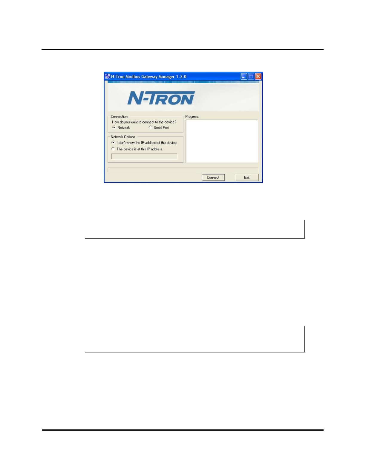
The Modbus Gateway Manager Device Discovery window appears.
Figure 12. Modbus Gateway Manager Discovery Window
2. Configure your Modbus gateway as required.
Note: For more information on configuration options refer to Section 4: Description of Modbus
gateway Properties.
Configuring with the Web Interface
ESERV-M12T Modbus Gateways can be configured over the network using a standard internet browser such as
Internet Explorer or Firefox.
To open the web configuration interface:
1. On a PC connected to the network, open a browser.
2. In the browser’s address bar, type the IP address of the Modbus gateway.
Note: Your Modbus gateway comes from the factory pre-configured to receive an IP address
assignment from a DHCP server. If a DHCP Server is not available on your network, it will default
to 169.254.102.39.
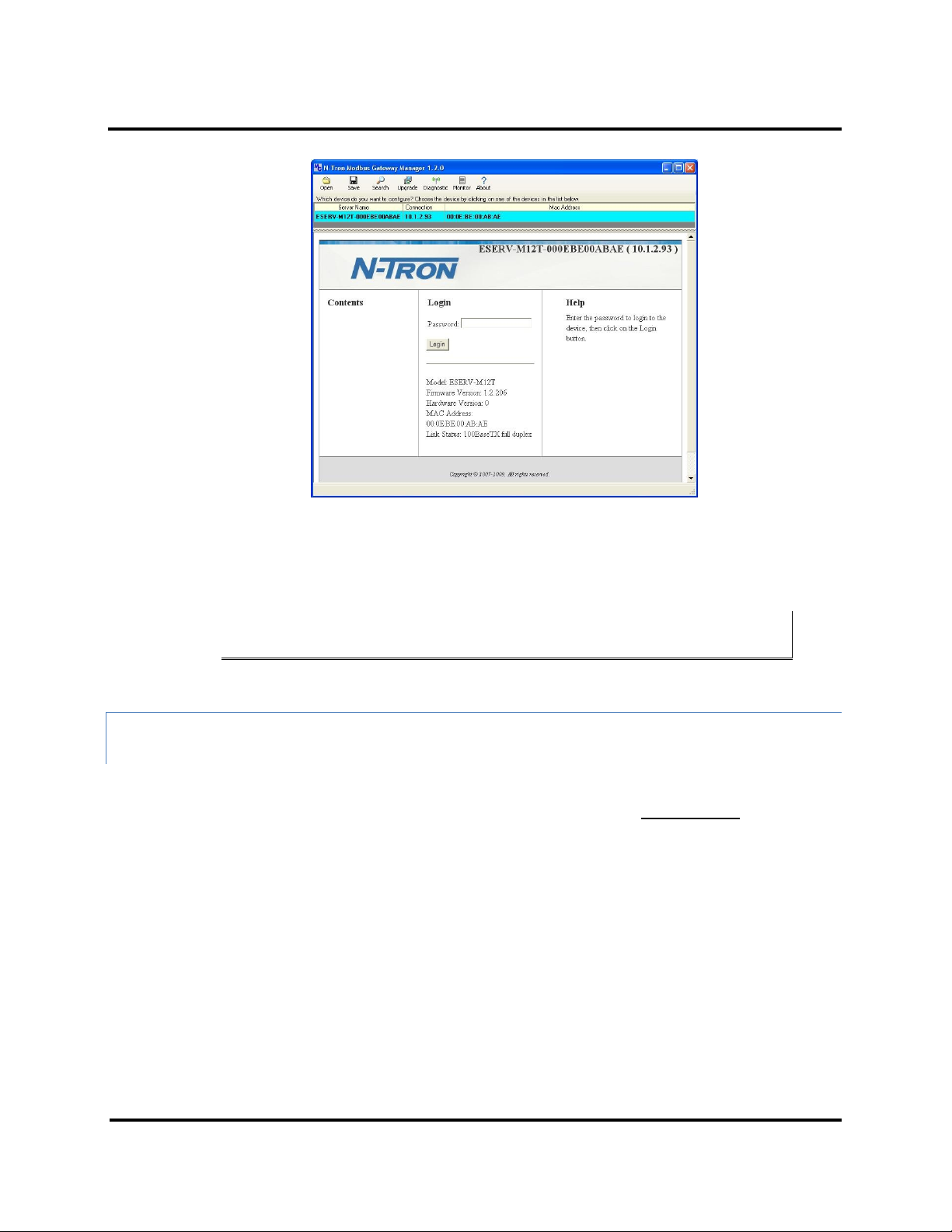
The web interface Login page appears.
11 ESERV-M12T (Rev. 1210)
Page 17
Setup and Connections ESERV-M12T Modbus Gateway
Figure 13. Modbus Gateway Manager Login Screen
3. Configure your Modbus gateway as required.
Note: For more information on configuration options refer to Section 4: Description of Modbus
Gateway Properties.
CONFIGURING THE ESERV-M12T MODBUS GATEWAY ON NETWORKS WITHOUT A DHCP
SERVER
Your Modbus Gateway comes from the factory set up to receive an IP assignment from a DHCP Server. If there is
not a DHCP server on your network, the Modbus Gateway will default to IP address 169.254.102.39. If this address
does not work with your PC, there are two methods to manually configure the network information.
1. Method 1: Change your PC Network to Match the Modbus Gateway
a. Open your network connection
12 ESERV-M12T (Rev. 1210)
Page 18
Setup and Connections ESERV-M12T Modbus Gateway
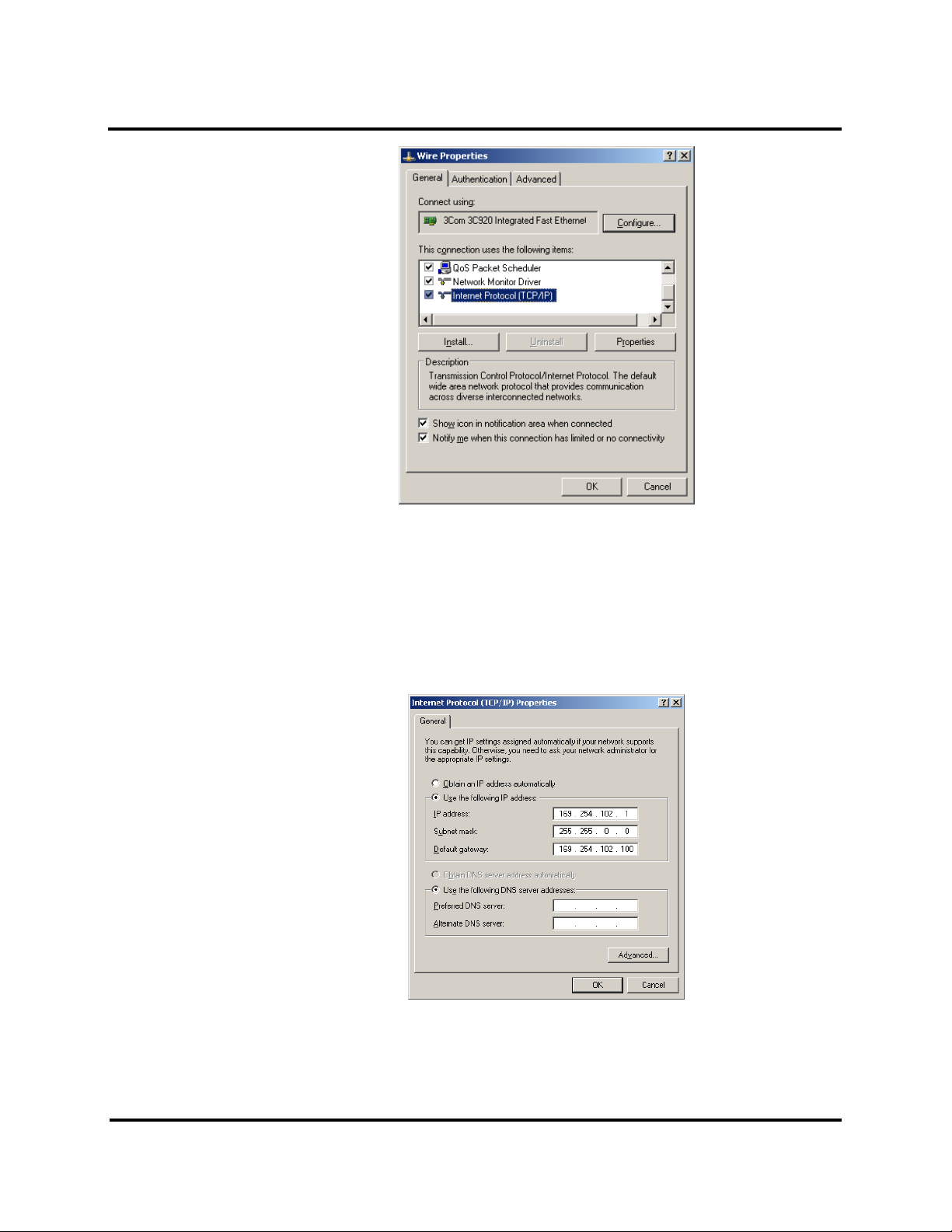
b. Click on Internet Protocol (TCP/IP) and click <properties>. Change the parameters to the
following:
IP Address = 169.254.102.1
Subnet Mask = 255.255.0.0
Default Gateway = 169.254.102.100
c. Use the Modbus Gateway Manager Software to search for, discover, and configure the
Modbus Gateway.
13 ESERV-M12T (Rev. 1210)
Page 19

Setup and Connections ESERV-M12T Modbus Gateway
Model
Port 1 LED
Port 2 LED
Ready LED
ESERV-M12T
OFF
ON
OFF
2. Method 2: Change the Modbus Gateway’s network settings to match your PC using Console Mode
a. Connect a null modem serial cable (crossover cable) from port 1 on the Modbus Gateway to
an available COM port on your PC.
b. Open Hyper Terminal or similar serial emulation software and connect to the COM port used
in step one. Ensure the port is configured to 115,200 baud, 8 data bits, no parity, and 1 stop
bit.
c. Enter Console Mode. Press and hold the Modbus Gateway’s for 2 to 10 seconds. The LED
indicators will respond as follows:
d. Release the reset button. The READY LED will blink once per second for five seconds. This
indicates that the Modbus Gateway is re-booting in Console Mode.
e. When the Modbus Gateway has successfully restarted in Console Mode, the READY LED will
be OFF and the PORT 1 LED will be ON.
f. Open the Ethernet Modbus Manager Software and select “Serial Port” as the method to
connect to the Modbus Gateway.
g. After logging in, click on <Network>.
h. Un-check the box next to “I Want DHCP to setup the Network.”
i. Re-configure the Modbus Gateway’s network settings to something within the range of your
PC’s network settings. For example:
PC Network Settings
IP Address = 192.168.0.1
Subnet Mask = 255.255.0.0
Default Gateway = 192.168.0.100
Change the Modbus Gateway’s network settings to:
IP Address = 192.168.0.50
Subnet Mask = 255.255.0.0
Default Gateway = 192.168.0.100
14 ESERV-M12T (Rev. 1210)
Page 20
Setup and Connections ESERV-M12T Modbus Gateway
j. Save the settings and remove power from the Modbus Gateway.
k. Re-apply power. Open the Ethernet Modbus Gateway Manager Software and select
“Network” as the method to connect to the device.
CONFIGURING THE ESERV-M12T MODBUS GATEWAY VIA THE SERIAL PORT (CONSOLE
MODE)
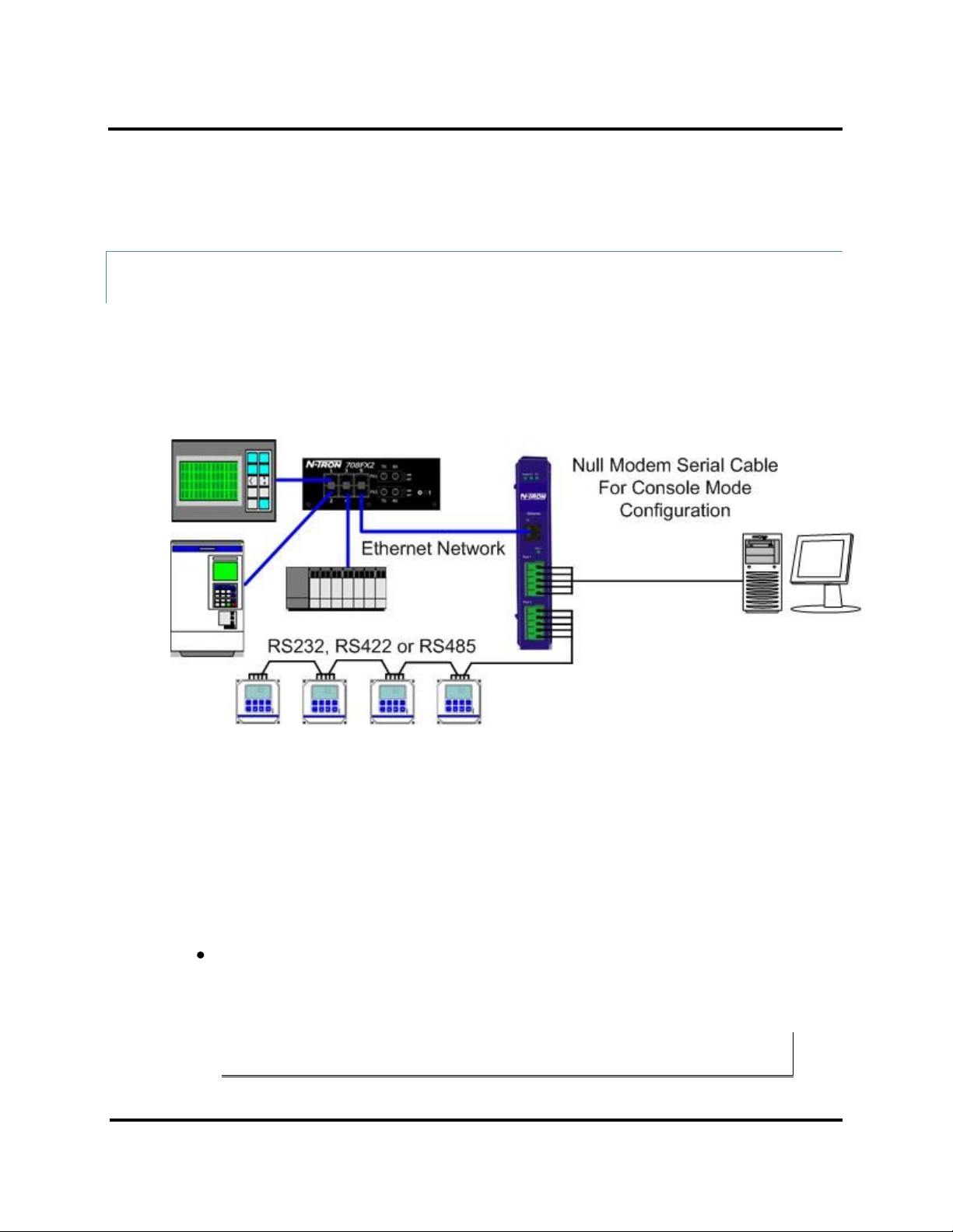
Your Modbus gateway can be configured via a serial port using the Ethernet Modbus Gateway Manager. To use
this feature the Modbus gateway's serial port must be connected to the serial port of a PC (using a null modem
cable).
Figure 14. Console Mode Setup
To configure the Modbus gateway it must be put into Console Mode, using the Mode switch.
To enter Console Mode, press and hold the Mode switch for between two and ten seconds. The LED indicators
respond as follows:
1. The Ready LED blinks three times per second while the button is being pressed.
2. The Modbus gateway is in Console Mode when:
Port 1 LED on the ESERV-M12T is On and the Port 2 LED is Off.
To configure the Modbus gateway, open the Modbus Gateway Manager software and set up the Modbus
gateway's parameters as required.
Note: For more information on configuration options refer to Section 4: Description of Modbus
Gateway Properties.
15 ESERV-M12T (Rev. 1210)
Page 21
Setup and Connections ESERV-M12T Modbus Gateway
To exit Console Mode, press and hold the Reset switch for two seconds, or turn off the power from the ESERVM12T, wait a few seconds, and turn the power on again.
The LEDs go back to their normal states when the device resumes normal operation.
ESERV-M12T MODBUS GATEWAY OPERATIONAL CONNECTI ONS
ESERV-M12T Modbus Gateways can operate in Direct IP Mode.
USING ESERV-M12T MODBUS GATEWAY S IN DIRECT IP MODE
A Direct IP connection allows applications using TCP/IP socket programs to communicate with the COM ports on
the Modbus gateway. In this type of application the Modbus gateway is configured as a TCP server. The socket
program running on the PC establishes a communication connection with the Modbus gateway. The data is sent
directly to and from the serial port on the server.
To set up a Direct IP Mode connection:
1. Connect the Modbus gateway to the network and a Modbus network as described in
previous sections.
2. Configure the Modbus gateway with the appropriate network settings (using
Modbus Gateway Manager or the web interface).
3. Configure your software application with the appropriate IP address and port
number to communicate with the Modbus network(s).
Figure 15. Direct IP Connection
16 ESERV-M12T (Rev. 1210)
Page 22

Setup and Connections ESERV-M12T Modbus Gateway
INITIATING A HARDWARE RESET ON THE MODBUS GATEWAY
To initiate a Hardware Reset on the Modbus gateway, press and hold the Mode switch for 0 to 2 seconds, and
then release it. The LED indicators respond as follows:
1. The Ready LED blinks three times per second while the button is being pressed.
2. The Modbus gateway is in Reset Mode when:
Port 1 LED on the ESERV-M12T is On and the Port 2 LED is Off.
3. The LEDs go back to their normal states when the device resumes normal operation.
RELOADING FACTORY DE FAULTS
To reload Factory Defaults, press and hold the Mode switch for more than 10 seconds. The LED indicators respond
as follows:
1. The Ready LED blinks three times per second while the button is being pressed.
2. The Modbus gateway is in Factory Default Mode when:
Port 1 LED on the ESERV-M12T and the Port 2 LED are both On.
The Modbus gateway reloads all factory default configuration parameters.
3. The LEDs go back to their normal states when the device resumes normal operation.
Note: Factor default parameters are listed in Appendix A
17 ESERV-M12T (Rev. 1210)
Page 23

Properties ESERV-M12T Modbus Gateway ESERV-M12T Modbus Gateway
DESC R I PTION, MODBUS G A T EWAY PROPERTIES
The following ESERV-M12T Modbus Gateway properties are ordered alphabetically to assist you in finding the
information you need.
ATTACHED
The Attached is selectable between Master and Slaves. If Master is selected, it will run in TCP server mode, if
Slaves is selected, it will run in TCP client mode.
BAUD RATE
Baud Rate is the communication speed of the link between the Modbus gateway and the device attached to its
serial port. Both these devices must be configured to operate at the same baud rate. Baud rate values range from
75 to 230,400 Baud. (Refer to Appendix B for specific baud rates that are supported.)
CHARACTER TIMEOUT
Character Timeout controls the maximum duration between received characters before sending the characters to
the network. Larger values may decrease the number of network packets, but increase the amount of time to
receive characters. Smaller values may increase the number of network packets, but decrease the amount of time
to receive characters. The range is 1 through 65535.
CONFIGURATION FILES
Configuration files contain all configuration settings for the Modbus gateway. When the Modbus gateway settings
have been configured you can save the settings using The Ethernet Modbus Gateway Manager. Existing
configuration files can be Opened (from the Ethernet Modbus Gateway Manager), which loads them into the
Modbus gateway. This allows the same configuration to be applied to multiple Modbus gateways, or to reload a
previously used configuration.
DATA/PARITY/STOP
The number of Data bits, type of Parity and number of Stop bits selected define the serial port parameters at
which the Modbus gateway will operate. These parameters must be configured to match the parameters set on
the Modbus network connected to the Modbus gateway's serial port.
Data Bits controls the number of bits of data in each character. Options include 5, 6, 7 or 8 data bits.
Parity controls the error checking mode. Options are No Parity, Odd, Even, Mark or Space.
Stop Bits controls the number of bits to indicate the end of a character. Options include 1, 1.5 and 2. (1.5 bits is
only valid when 5 data bits is selected, which is rare. The 2 stop bits setting is only valid when 6, 7 or 8 data bits is
selected.)
18 ESERV-M12T (Rev. 1210)
Page 24

Properties ESERV-M12T Modbus Gateway ESERV-M12T Modbus Gateway
DEFAULT GATEWAY
The Default Gateway address sets the default route to remote networks, enabling users to access the Modbus
gateway from outside the local network.
DHCP
DHCP (Dynamic Host Configuration Protocol) is a protocol used on special servers that supply IP addresses to
network nodes on request.
When DHCP is enabled on the Modbus gateway (factory default), on power up it sends a DHCP request to the
DHCP server, which assigns a dynamic IP address, subnet mask, and default server to the Modbus gateway.
When DHCP is disabled (static IP addressing), the IP Address, Subnet and Default Gateway fields must be set
manually by entering the appropriate addresses in these fields. If you do not know what addresses to use in these
fields, ask your network administrator.
Notes:
A dynamic address assigned by the DHCP server may change if the server loses the Ethernet
connection or power is removed. If a device on the network that normally communicates with the
Modbus gateway is configured to communicate with a specific IP address of the Modbus gateway,
and the IP address has been changed, the device will not be able to communicate with the Modbus
gateway. Therefore, disabling DHCP and using a static IP address is recommended. If a DHCP
server is not found on the network, the Modbus gateway automatically configures to IP address
169.254.102.39
FIRMWARE VERSION
The Firmware Version number (Vx.x.x) indicates the Modbus gateway's currently loaded firmware release. From
time to time new firmware is made available and can be uploaded into the Modbus gateway using the Ethernet
Modbus Gateway Manager.
HARDWARE VERSION
The Hardware Version number of the Modbus gateway hardware is displayed on the Login page of the Ethernet
Modbus Gateway Manager.
ID ROUTING
ID routing allows the gateway to manage slave device IDs between various Modbus interfaces. By filling in the user
defined slave ID table, a Modbus Gateway routes requests to the correct serial port. One connection can command
serial slaves on multiple serial ports.
19 ESERV-M12T (Rev. 1210)
Page 25

Properties ESERV-M12T Modbus Gateway ESERV-M12T Modbus Gateway
By filling in the drop down menu of ports with slave devices attached, adding IP addresses of slaves, up to 10
address ranges can be routed.
By default all boxes are unchecked, the drop down menu is set to serial port one, and all fill in boxes are blank.
IP ADDRESS
Software or hardware attempting to access the Modbus gateway via the network must know the IP Address of the
server. If DHCP is selected, the Modbus gateway requests and receives a dynamic IP address from a DHCP server
when it first connects to the network. If DHCP is not selected you must type in a static IP address when configuring
Network settings (on the Modbus Gateway Manager Network page). The static IP address remains the same each
time the server is powered up or starts/restarts.
ESERV-M12T Modbus gateways come from the factory preset to receive an IP assignment from a DHCP Server. If a
DHCP Server is not available on your network, it will default to 169.254.102.39. If you need to change the static IP
address and do not know what address to use, consult your network administrator.
LINK STATUS
Link Status of the currently selected Modbus gateway is shown on the Login page of the Ethernet Modbus
Gateway Manager. Link status indicates the type of Ethernet connection between the computer and Modbus
gateway. It will either display 10BaseT or 100BaseTX in full duplex or half duplex. Link status is dependent on the
LAN, switches, hubs used in the LAN topology.
MAC ADDRESS
The MAC Address is a hardware level address of the Modbus gateway that cannot be changed. It is assigned in the
factory. Every Ethernet device manufactured has its own unique MAC address. The MAC address of each Modbus
gateway is printed on the device's label. The MAC address of the currently selected Modbus gateway is also
displayed on the Login page of the Ethernet Modbus Gateway Manager.
MODBUS PRIORITY
This allows the gateway to move high priority messages to the front of the serial message buffer. The priority can
be based on the originating IP address, the Modbus ID, the Modbus function code, or any combination of the
three. Up to five different priorities can be set.
The default will have all the check boxes unchecked and all the fill in boxes blank.
20 ESERV-M12T (Rev. 1210)
Page 26

Properties ESERV-M12T Modbus Gateway ESERV-M12T Modbus Gateway
MODBUS SERIAL RETRIE S
This is the maximum number of times that the Modbus gateway will retry to send a Modbus message to a Modbus
client, before reporting a 0Bh exception if it is selected. This should be limited to between 0 and 5.
MODBUS ASCII
The Modbus ASCII message protocol is a human readable version of the Modbus message, and is one of the three
Modbus formats supported by the ESERV-M12T Modbus Gateway.
A major advantage of Modbus ASCII is it allows up to a 1 second gap between bytes. It uses a Longitudinal
Redundancy Check (LRC) checksum to verify message accuracy.
MODBUS MESSAGE BUFFERING
The ESERV-M12T has two Modbus serial buffers, one for each serial port. Each will buffer up to 32 Modbus
messages. These buffers help ensure messages don’t get lost in a data traffic jam, and are part of what makes
Modbus such an outstandingly reliable serial protocol.
MODBUS MESSAGE TIMEO UT
Message timeout is supported by the ESERV-M12T. This is the maximum amount of time before a response to a
message is expected.
MODBUS RTU MESSAGE
The Modbus RTU message is broken into 4 different parts. The address field, the function code, this is copied
directly over from the Modbus TCP message, the data and the error check, a 16 bit cyclic redundancy check or CRC.
MODBUS SERIAL CONTRO L
MESSAGE TIMEOUT
The message timeout is the maximum time the gateway allows for a response from the slave device. The default is
1000ms.
21 ESERV-M12T (Rev. 1210)
Page 27

Properties ESERV-M12T Modbus Gateway ESERV-M12T Modbus Gateway
CHARACTER TIMEOUT
The character timeout is the maximum time the gateway allows between characters from the slave device, used
only in RTU mode. The default is 10ms.
CRC/LRC ERROR CHECK
The CRC/LRC check calculates the CRC/LRC for the message received, and compares this to the CRC/LRC with the
message. If not the same the message is rejected.
MESSAGE RETRIES
Message retries is the number of times the gateway resends the message if it gets a character timeout or CRC/LRC
error. The default is two.
MODBUS TCP MESSAGE
The Modbus TCP message may be broken up into multiple different TCP frames. The Modbus TCP message
contains three main blocks to the Modbus TCP message. The first is the MBAP header. It describes the Modbus
message, including the Transaction Identifier, Protocol Identifier, Length and Unit ID. The second part is the
Function Code. The third is the Data. The Function Code and Data are the standard Modbus PDU.
MODEL
The Model number of the currently selected Modbus gateway is displayed on the Login page of the Ethernet
Modbus Gateway Manager.
NETWORK MODE
The network mode is the method used to configure the network parameters. It is either “DHCP” or “Static IP”.
NETWORK PROTOCOLS
Network Protocols available for use on ESERV-M12T Modbus gateways include TCP.
22 ESERV-M12T (Rev. 1210)
Page 28

Properties ESERV-M12T Modbus Gateway ESERV-M12T Modbus Gateway
PASSWORD
When you first receive the ESERV-M12T Modbus gateway from the factory the Password is blank so that you can
initially access the Modbus gateway without entering a value into this field. To ensure security you should create
and save a password the first time you configure the Modbus gateway. After a password has been set up it must
be entered each time you login to the Ethernet Modbus Gateway manager. The password is used to access the
configuration pages from the Ethernet Modbus Gateway Manager Login page and can be changed from the
General page.
PORT# ID REMAP
This allows the gateway to remap the Modbus ID to another ID on the serial port. This would be used when there
are two identical Modbus serial networks talking to Modbus TCP controllers.
The first box is the staring ID of a range you want to remap; the second box is the last ID of that range. If you are
just remapping one ID the second box is not filled in. The third box is the start of the remap range on the serial
port. The fourth box will auto fill in based on the range filled in the first 2 boxes. The range must check to make
sure it is a valid range, and does not overlap with any of the other ranges set. Up to 5 address ranges can be
remapped per port.
The default will have all the check boxes unchecked, and all fill in boxes blank.
SERIAL INTERFACE MOD ES
Four serial interface modes of operation are:
RS-232 - Point-to-point serial communications connection used by PC COM ports
and many other systems. Capable of baud rates up to 115.2 kbaud over short
distances (typically 50 feet).
RS-422 - Point-to-point communications using a transmit pair and a receive pair.
RS-422 can operate at higher speeds and longer distances than RS-232.
RS-485 2-wire - Similar speed and distance specifications as RS-422 but allows
multidrop connections.
23 ESERV-M12T (Rev. 1210)
Page 29

Properties ESERV-M12T Modbus Gateway ESERV-M12T Modbus Gateway
RS-485 4-wire - Similar speed and distance specifications as RS-422 but allows
multi-drop and full duplex connections.
Select the appropriate serial interface mode for the type of connection between the Modbus
gateway's serial port and the device connected to it.
Note: Refer to the Appendix D for connector and pin-out details.
MODBUS GATEWAY NAME
Modbus Gateway Name is a unique name assigned to the Modbus gateway. It must be a valid hostname as
defined by RFC-952 and RFC-1123. The rules are:
It must consist only of the characters "A" to "Z", "a" to "z", "0" to "9" or "-"
It can start or end with a letter or a number, but it must not start or end with a "-
".
It must not consist of all numeric values.
GATEWAY SERIAL PORT NUMBER
The Gateway Serial Port Number of the currently selected port is shown in this field.
The ESERV-M12T Modbus Gateways features two serial ports.
SUBNET MASK
The Subnet Mask specifies the network mask the Modbus gateway uses when on a subnetted network.
For a Class A network (IP addresses 0.0.0.0 through 127.255.255.255) the default
subnet mask is 255.0.0.0.
For a Class B network (IP addresses 128.0.0.0 through 191.255.255.255) the
default subnet mask is 255.255.0.0
For a Class C network (IP addresses 192.0.0.0 through 233.255.255.255) the
default subnet mask is 255.255.255.0
24 ESERV-M12T (Rev. 1210)
Page 30

Properties ESERV-M12T Modbus Gateway ESERV-M12T Modbus Gateway
For a Class D network (IP addresses 224.0.0.0 through 239.255.255.255) and
Class E Networks (IP addresses 240.0.0.0 through 255.255.255.255) the subnet
mask is ignored.
ESERV-M12T Modbus Gateways come from the factory with a default subnet
mask value of: 255.255.255.0
TCP (TRANSMISSION CO NTROL PROTOCOL)
TCP (Transmission Control Protocol) provides reliable connection-oriented network communication with error
checking. In TCP mode the Modbus gateway can be configured as a client or a server.
When the Modbus gateway is configured as a TCP client it initiates connections with a server on the network. You
must set up the IP address and port number of the server that you want the client (Modbus gateway) to
communicate with. You also select whether the Modbus gateway is to connect at power up or only when it
receives data from the device connected to its serial port.
When the Modbus gateway is configured as a TCP server it waits for connections to be initiated by another
network device. You must set up the TCP port number that it will listen to for connections and set the maximum
(up to eight) number of simultaneous connections it will accept. You can filter the connections it will accept based
on specific IP addresses or ranges of IP addresses that you specify.
25 ESERV-M12T (Rev. 1210)
Page 31

Upgrading Firmware ESERV-M12T Modbus Gateway
UPGRADING THE MODBUS GATEWAY FIRMWARE
Occasionally, updated firmware may become available for your Modbus gateway. The firmware can be upgraded
using the Ethernet Modbus Gateway Manager software. The following procedure describes the firmware updating
process:
1. Click the Upgrade button to open the Firmware Upgrade dialog box.
Figure 16. Firmware Upgrade Dialog Box
The name of the currently selected Modbus gateway appears in the top drop down list. Other
Modbus gateways (that have already been discovered) can be selected from the drop down list, if
desired.
The current firmware version of the selected Modbus gateway is shown in the text below the
Modbus gateway name.
Information about the selected firmware file is shown in the third text box.
DOWNLOADING FIRMWARE FILES
The Firmware File list (second box) displays all firmware files in the firmware installation folder. Only firmware that
is compatible with the selected Modbus gateway is available in this list.
To download the latest firmware files from a file:
1. Click the Browse button to open an Open File dialog box.
2. Browse to the drive and folder containing the firmware file.
26 ESERV-M12T (Rev. 1210)
Page 32

Upgrading Firmware ESERV-M12T Modbus Gateway
3. Select and download the file to the local firmware folder.
UPLOADING THE FIRMWA RE TO THE MODBUS GATEWAY
To upgrade the firmware:
1. In the Modbus Gateway Selection drop down list, select the Modbus gateway to be
upgraded.
2. In the Firmware Description drop down list, select the firmware to upload to the
Modbus gateway.
3. Click the Upgrade button.
Progress Bar and Progress Box provides information on the progress of the transfer.
4. In the Firmware File drop down list, select the firmware file to upload to the
Modbus gateway.
5. Click Upgrade.
The Progress box and Progress bar display information on the upgrading process.
6. When the upgrade process is complete, click Close.
27 ESERV-M12T (Rev. 1210)
Page 33

Diagnostics ESERV-M12T Modbus Gateway
DIAGNOSTICS
Clicking the Diagnostics icon opens the Diagnostics dialog box and enables you to check the operation of
connected Modbus gateways on the local computer.
The Computer Information box displays information about the type of network connections, the IP addresses,
Subnet Masks and Default Gateways in use.
Figure 17. Diagnostics Dialog Box
TESTING A MODBUS GATEWAY CONNECTION
To run diagnostics on a Modbus gateway:
1. Click the Diagnostics icon.
The Diagnostics dialog box appears.
2. In the drop down box select the specific Modbus gateway you want to check.
3. Click the Start button
28 ESERV-M12T (Rev. 1210)
Page 34

Diagnostics ESERV-M12T Modbus Gateway
Information about the progress of the pinging process is displayed in the Test Progress box.
Figure 18. Testing a Modbus Gateway Connection
29 ESERV-M12T (Rev. 1210)
Page 35

Modbus Help ESERV-M12T Modbus Gateway
APPLICATION EXAMP L ES
Modbus gateways can be used to integrate Modbus networks in a wide variety of settings. But as each setting has
its own requirements, users may not understand how a gateway helps, or if it’s appropriate for their specific
needs.
The following scenarios are examples only, and many others are possible. Contact N-TRON technical support for
information on other applications.
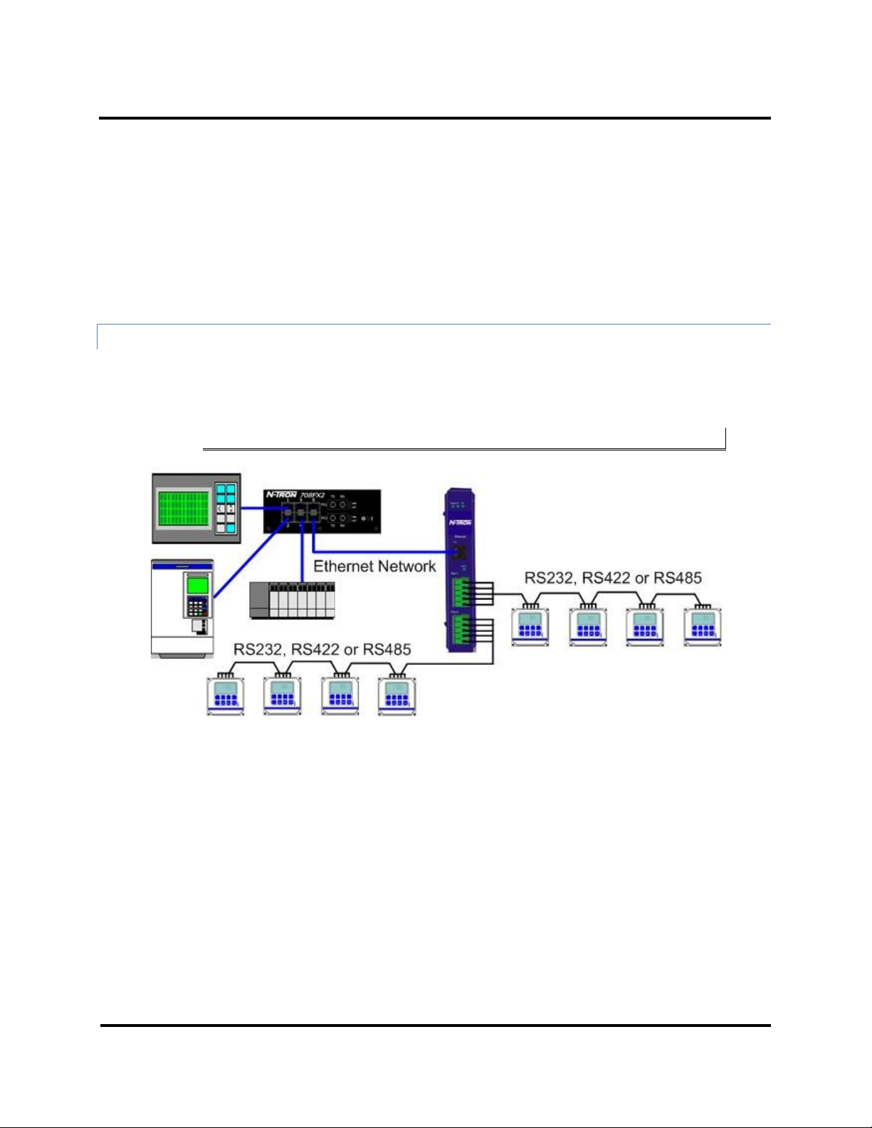
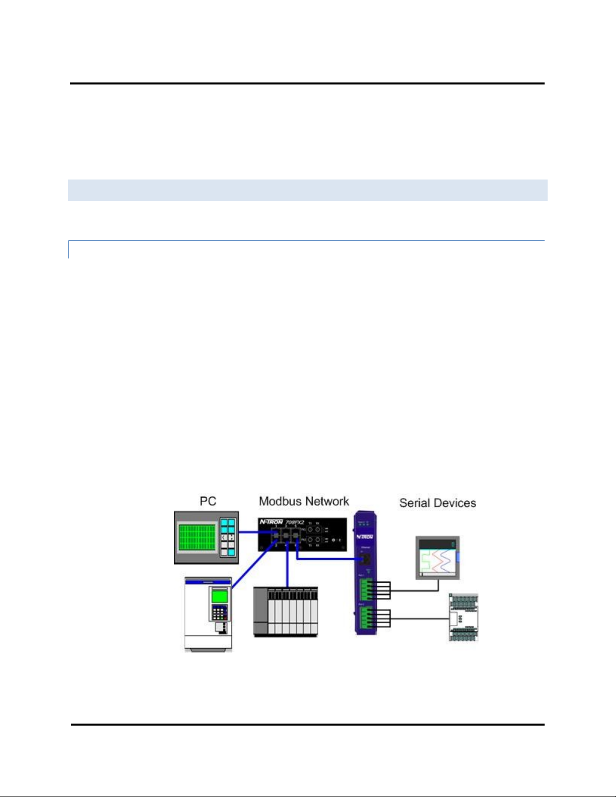
ETHERNET MASTER AND SERIAL SLAVES
Your Modbus gateway can be used to integrate serial slave devices on a Modbus TCP network. This allows TCP
Masters to control serial slave devices. The example below is using a gateway with two serial ports.
Figure 19. Ethernet Master With Serial Slaves
1. Log into your gateway.
2. Access the serial port one setup screen by clicking the link on the left side of the screen.
30 ESERV-M12T (Rev. 1210)
Page 36

Modbus Help ESERV-M12T Modbus Gateway
Figure 20. Serial Port 1 Setup
3. Configure Serial Port 1. In this case it is RS-232, 19.2 kbps, 8 data bits, 1 stop bit, and even parity. Save
the settings
4. Access Port 1 Modbus by clicking the link on the left side of the screen.
31 ESERV-M12T (Rev. 1210)
Page 37

Modbus Help ESERV-M12T Modbus Gateway
Figure 21. Port 1 Modbus
5. Configure the Port 1 Modbus Settings. In this case Attached should be slaves, Modbus should be RTU.
The other settings depend on your application.
6. Configure Port 2 Serial and Modbus is the same fashion.
7. Access Modbus ID Remapping for each port and configure as necessary.
32 ESERV-M12T (Rev. 1210)
Page 38

Modbus Help ESERV-M12T Modbus Gateway
Figure 22. Port x Modbus Slave ID Remapping
8. Access Modbus ID Routing. Configure as necessary. In this example, Slave ID 200 is mapped to serial
port 1, Slave ID 1 through 5 and 205 are mapped to serial port 2.
33 ESERV-M12T (Rev. 1210)
Page 39

Modbus Help ESERV-M12T Modbus Gateway
Figure 23. Modbus ID Routing
9. Access Modbus Priority and configure as necessary.
34 ESERV-M12T (Rev. 1210)
Page 40

Modbus Help ESERV-M12T Modbus Gateway
Figure 24. Modbus Priority
35 ESERV-M12T (Rev. 1210)
Page 41

Modbus Help ESERV-M12T Modbus Gateway
Serial & Ethernet Masters, Serial & Ethernet Slaves
Your Modbus Gateway can also integrate multiple master devices onto serial and Ethernet Networks.
Figure 25. Serial & Ethernet Masters, Serial & Ethernet Slaves
1. In this example, Serial Port 1 has an RTU Master attached. Configure the serial port settings as
appropriate for the device. Access the Port 1 Modbus screen and configure it the port for Modbus
Master and RTU.
36 ESERV-M12T (Rev. 1210)
Page 42

Modbus Help ESERV-M12T Modbus Gateway
Figure 26. Port 1 Modbus
2. Configure the Modbus Slave ID routing. In this case Modbus Slaves 1 through 5 and 205 are on Serial
Port 2. Modbus Slaves 150 and 151 through 160 have IP assignments.
37 ESERV-M12T (Rev. 1210)
Page 43

Modbus Help ESERV-M12T Modbus Gateway
Figure 27. Modbus Slave ID Routing
SERIAL MASTERS, IP S LAVES
Serial Masters can be used to control IP Slaves.
Figure 28. Serial Masters, IP Slaves
38 ESERV-M12T (Rev. 1210)
Page 44

Modbus Help ESERV-M12T Modbus Gateway
1. In this example, and ASCII Master is connected to Serial Port 1 and an RTU Master is connected to
Serial Port 2. Configure the serial ports as appropriate for these devices.
Figure 29. Port 1 Serial
39 ESERV-M12T (Rev. 1210)
Page 45

Modbus Help ESERV-M12T Modbus Gateway
Figure 30. Port 2 Serial
2. Access the Modbus screen for each port and configure as appropriate. In this case, Port 1 has an ASCII
Master and Port 2 has an RTU Master attached.
40 ESERV-M12T (Rev. 1210)
Page 46

Modbus Help ESERV-M12T Modbus Gateway
Figure 31. Port 1 Modbus
41 ESERV-M12T (Rev. 1210)
Page 47

Modbus Help ESERV-M12T Modbus Gateway
Figure 32. Port 2 Modbus
3. Setup the Slave ID Routing to associate IP addresses with the appropriate Slave ID.
42 ESERV-M12T (Rev. 1210)
Page 48

Modbus Help ESERV-M12T Modbus Gateway
Figure 33. Modbus Slave ID Routing
43 ESERV-M12T (Rev. 1210)
Page 49

Modbus Help ESERV-M12T Modbus Gateway
IDENTICAL HARD CODED SLAVES
In this example, two slave devices that are hard coded with the same ID are required. This is accomplished by
putting them on different serial ports.
Figure 34. Identical Hard Coded Slaves
44 ESERV-M12T (Rev. 1210)
Page 50

Modbus Help ESERV-M12T Modbus Gateway
IDENTICAL PRODUCTION LINES
In this example, identical or backup production lines can be controlled by the same IP Master. This allows the
duplicate networks to be configured identically, saving documentation and maintenance time.
Figure 35. Identical Production Lines
45 ESERV-M12T (Rev. 1210)
Page 51

Modbus Help ESERV-M12T Modbus Gateway
MODBUS ASCII/RTU BASICS
The Modbus protocol emerged in the mid-1970s as an early protocol for linking terminals with Modicon PLCs using
a master/slave (sometimes called a master/client) relationship. A simple, open, message-based protocol, it caught
on quickly and became a de facto standard in the industry. It supports asynchronous point-to-point and multidrop
communications and can be used with a variety of serial interfaces (RS-232, RS-422, RS-485, modems, etc).
The original Modbus specification included two possible transmission modes: ASCII and RTU. Modbus RTU mode is
the most common implementation, using binary coding and CRC error-checking. Modbus ASCII messages, though
somewhat more readable because they use ASCII characters, is less efficient and uses less effective LRC error
checking. ASCII mode uses ASCII characters to begin and end messages whereas RTU uses time gaps (3.5 character
times) of silence for framing. The two modes are incompatible so a device configured for ASCII mode cannot
communicate with one using RTU.
All Modbus communications are initiated by Modbus masters using a polling query/response format. The master
can send broadcast messages (using a slave address of 0), which all slaves accept, but do not reply to. More
commonly the master polls individual slaves sequentially. In each poll it sends a message containing a device
address, followed by a function code, any data that maybe required, and an error check field. The addressed slave
responds with a similar message structure. Typically it repeats back its address and the function code, and then
sends a field indicating the number of bytes of data it is sending, followed by the data and the error check field.
Slave addresses can range from 1 to 247. Function codes include several common ones typically used in all
applications, and additional ones that may be implemented in specific cases. Common function codes include:
Read Coil Status (01), Read Input Status (02), Read Holding Registers (03) and Read Input Registers (04).
When a master sends a message to a slave it expects to receive a valid response within certain length of time. If
the slave does not receive the message, or if the slave receives the message but an error is detected, it does not
respond. If the slave cannot respond appropriately for some other reason (e.g. it does not recognize the function
code), it will return a message containing an exception response.
HINTS AND TIPS
A few simple suggestions that may assist you if your system is experiencing problems include:
Slowing down the polling rate may be helpful if power cycling doesn’t cure the
problem.
A common misperception is that every serial network must terminate with a
resistor. While this was true of early serial network configurations, it’s typically the
wrong answer – call our technical support and verify if you’re an exception, at 251342-2164.
A sometimes difficult problem is difference in grounding voltage between various network locations. Stray voltage
from lightning or other sources may also find its way onto the network. These conditions make isolation necessary
in many settings.
46 ESERV-M12T (Rev. 1210)
Page 52

Appendices ESERV-M12T Modbus Gateway
APPENDICES
This section includes the following Appendices:
Appendix A: Default Gateway Settings
Appendix B: Product Specifications
Appendix C: Dimensional Diagrams
Appendix D: Connector Pin outs
47 ESERV-M12T (Rev. 1210)
Page 53

Appendices ESERV-M12T Modbus Gateway
Setting
Default Value
Gateway Name
TBD
Password
password field is blank from factory
DHCP
Enabled
IP Address
DHCP will configure. If a DHCP Server is
not available, the unit will default to
169.254.102.39
Net Mask
255.255.0.0
Gateway
169.254.102.100
MAC Address
Fixed - see bottom label
Firmware Version
(Vx.x.x)
Hardware Version
(Vx.x.x)
Port
1, 2
Serial port mode
RS-232
Baud Rate
9600
Data bits
8
Parity
None, Even, Odd, Mark, Space
Stop bits
1 & 2
APPENDIX A: DEFAULT GATEWAY SETTINGS
48 ESERV-M12T (Rev. 1210)
Page 54

Appendices ESERV-M12T Modbus Gateway
Flow Control
None
Protocol
TCP
Serial timeout
0 seconds
Inter-character timer
0 ms
TCP port
Port 1 = 4000
Port 2 = 4001
Max connection
1
49 ESERV-M12T (Rev. 1210)
Page 55

Appendices ESERV-M12T Modbus Gateway
APPENDIX B: PRODUCT SPECIFIC ATIONS
This section includes the following specifications:
General Specifications
Controls, Indicators and Connector Specifications
Serial Interface Specifications
Network Specifications
50 ESERV-M12T (Rev. 1210)
Page 56

Appendices ESERV-M12T Modbus Gateway
Hardware and included
accessories
Device
ESERV-M12T Modbus gateway module
CD
CD with Ethernet Gateway Modbus Manager software for
Windows 2000, 2003 Server/XP/Vista x32
Optional Accessories
NTPS-24-1.3 Power Supply
DIN-RAIL Power Supply, 1.3 Amp @24 VDC
Configuration Options
Via serial port
Using Ethernet Modbus Gateway Manager via a serial
connection, (press Reset button to enter Console Mode)
Via network
Using Ethernet Modbus Gateway Manager via a Ethernet
connection
Using a standard web browser such as Internet Explorer
6.0/7.0 or Firefox 1.5/2.0
Software
Modbus Gateway Manager for
Modbus gateway configuration
Windows 2000, 2003 Server, XP, & Vista x32
Environment
Operating Temperature
-34 to 80 °C (-29 to 176 °F)
Storage Temperature
-40 to 85 °C (-40 to 185 °F)
Operating Humidity
10 to 90% non-condensing
Certifications
FCC
Part 15 Class A
CE
CISPR (EN55022) Class A
EN61000-6-1 Generic Standards for Residential,
Commercial & Light Industrial
GENERAL SPECIFICATIO NS
51 ESERV-M12T (Rev. 1210)
Page 57

Appendices ESERV-M12T Modbus Gateway
EN61000-4-2 to 11 ESD, RFI, EFT, Surge, and CI
UL
508
Enclosure
Rating
IP30
Mounting
DIN rail mount (35 mm)
Dimensions, Small Case
1.2 in x 3.3 x 4.7 in (3.1 x 8.4 x 11.9 cm)
Power Supply
(External Supply
Required)
Voltage Requirements
10 to 58 VDC
Power Consumption
ESERV-M12T – 4.0W (Max)
52 ESERV-M12T (Rev. 1210)
Page 58

Appendices ESERV-M12T Modbus Gateway
Switches
Reset button
Hold in for 0 to 2 seconds for hardware reset
Hold in for 2 to 10 seconds for Console Mode (Do a hardware reset or recycle
power to exit Console Mode)
Hold in for more than 10 seconds to reset to factory defaults
Indicators
Serial LED
(one per port)
Color = Green
On = Port open
Blink = Data traffic
Link LED
Color = Green
On = 100BaseTX
Off = 10BaseT
Blink = Data traffic
Ready LED
Color = Green
Blink (once per second) = System OK
Off = System NOT OK
Connectors
10BaseT/100BaseTX
Ethernet
Single RJ-45F (8 pin)
ST fiber
ST connector
Serial
Two pluggable lockable 5.08 mm terminal blocks
DC Power
5.08mm 2-position pluggable, lockable terminal block
CONTROLS, INDICATORS AND CONNECTOR SPE CIFICATIONS
53 ESERV-M12T (Rev. 1210)
Page 59

Appendices ESERV-M12T Modbus Gateway
Mode Selection
RS-232/422/485 software selectable
RS-232 lines
TXD, RXD, RTS, CTS, DTR, DSR, DCD, GND
RS-422 lines
TXDA(-), TXDB(+), RXDA(-), RXDB(+), GND
RS-485 lines (2 wire)
Data A(-), Data B(+), GND
RS-485 lines (4 wire)
TXDA(-), TXDB(+), RXDA(-), RXDB(+), GND
Baud Rates
75, 150, 300, 600, 1200, 2400, 4800, 7200, 9600, 14400, 19200, 28800, 38400, 57600, 115200,
230400
Data Bits
5, 6, 7, 8
Parity
None, even, odd, mark, space
Stop bits
1, 1.5, 2
Flow control
None, RTS/CTS, XON/XOFF
RS-422/485 biasing
Auto 4.7K ohm pullups and pulldowns
RS-422/485
termination
Auto termination with thru hole resistor (user supplied)
RS-485 data control
Auto control via MCU
SERIAL INTERFACE SPE CIFICATIONS
54 ESERV-M12T (Rev. 1210)
Page 60

Appendices ESERV-M12T Modbus Gateway
Fiber
Interface
Fiber Mode
Multimode
Range
2km
Cable
62.5/125μm
Connector
ST TX Power Min
-19 dBm
RX Sensitivity
Max
-32 dBm
Wavelength
1310 nm
FIBER INTERFACE SPECIFICATIONS
55 ESERV-M12T (Rev. 1210)
Page 61

Appendices ESERV-M12T Modbus Gateway
Memory
Serial Memory
10 K bytes per port
Network Memory
10 K bytes
I/P Port Addresses
5300
Configuration setting in TCP Mode
8888
ESERV-M12T update
Network Communications
LAN
10/100 Mbps Auto-detecting 10BaseT or 100BaseTX
Network Physical Layer
Standards
Ethernet
IEEE 802.3 auto-detecting & auto MDI/MDX 10BaseT and
100BaseTX
Protocols Supported
TCP, IPv4, ARP, Telnet, HTTP 1.0, ICMP/PING, DHCP/BOOTP
IP Mode
Static, DHCP or Auto IP
TCP
User definable
Connection Modes
Server, Client,
Search
Serial direct COM and Ethernet auto search or specific IP
Firmware Upgrade
Via serial, Ethernet or auto web search
Character count
0 to 65535
Timeouts
Character
0 to 65535 ms, default set at 10 ms
Modbus
Message
0 to 65535 ms, default set at 1,000 ms
Serial
0 to 65535 sec
NETWORK SPECIFICATIO NS
56 ESERV-M12T (Rev. 1210)
Page 62

Appendices ESERV-M12T Modbus Gateway
APPENDIX C: DIMENSIO NAL DIAGRAMS
Figure 36. Dimensional Diagram of an ESERV-M12T Modbus
57 ESERV-M12T (Rev. 1210)
Page 63

Appendices ESERV-M12T Modbus Gateway
Terminal
RS-232
RS-422/RS-485 4-
Wire
RS-485 2-Wire
A
RTS (Output)
TXA(-)
DATA A(-)
B
TD (Output)
TXB(+)
DATA B(+)
C
CTS (Input)
RXA(-)
---
D
RD (Input)
RXB(+)
--- E GND
GND
GND
APPENDIX D: CONNECTO R PINOUT
ESERV-M12T SERIAL PORT PINOUTS
In the RS-422 mode, TX lines are outputs and RX lines are inputs. Connect the Modbus gateway TXB(+) line to the
RXB(+) line of the Modbus network, and the Modbus gateway TXA(-) to the RXA(-) of the Modbus network.
Ground is signal ground and provides a common mode reference for the RS-422 Receiver and Transmitters.
58 ESERV-M12T (Rev. 1210)
Page 64

Appendices ESERV-M12T Modbus Gateway
RJ-45 Pin
Signal
Wire Color
1
TX+
White-Green
2
TX+
Green
3
RX+
White-Orange
4
Not used
Blue
5
Not used
White-Blue
6
RX-
Orange
7
Not used
White-Brown
8
Not used
Brown
STANDARD ETHERNET CABLE RJ-45 PIN-OUT
59 ESERV-M12T (Rev. 1210)
Page 65

Appendices ESERV-M12T Modbus Gateway
Term
Definition
ADU
Application Data Unit
ASCII
American Standard Code for Information Interchange
Baud Rate
Number of bits per second
CRC
Cyclical Redundancy Checking
Data Bits
Number of bits per byte, normally 7 with Modbus ASCII, and 8 with Modbus RTU
DHCP
Dynamic Host Configuration Protocol
Flow Control
The process of managing the rate of data transmission between two nodes.
Function Code
A code field that tells the Gateway what kind of action to perform
Modbus Gateway
A bridge to get from Modbus TCP to Modbus Serial
GUI
Graphical User Interface
IP
Internet Protocol
IPv4
Internet Protocol version 4
LED
Light emitting diode. Used as a visual indicator
MBAP
MODBUS Application Protocol
MEI
Multi Electrical Interface via RS-232/422/485
Modbus
A request/reply protocol and offers services specified by function codes.
Parity Bit
A binary digit that is added to ensure that the number of bits with value of one in a given
set of bits is always even or odd. It may also be a Mark (1), or a Space (0).
PDU
Protocol Data Unit
RS-232
Interface between Data Terminal Equipment and Data Circuit-Terminating Equipment
Employing Serial Binary Data Interchange
RS-422
Electrical Characteristics of Generators and Receivers for Use in Balanced Digital Point to
Point Systems
RS-485
Electrical Characteristics of Generators and Receivers for Use in Balanced Digital Multipoint
Systems
RTU
Remote Terminal Unit
GLOSSARY
60 ESERV-M12T (Rev. 1210)
Page 66

Appendices ESERV-M12T Modbus Gateway
Term
Definition
Stop Bit
Number of bit times after a character is transmitted before the next character can start
transmission.
TCP
Transmission Control Protocol
Unit ID
Unit Identifier. This is the same as the slaves address.
61 ESERV-M12T (Rev. 1210)
Page 67

Safety ESERV-M12T Modbus Gateway
Copyright, © N-Tron Corp., 2010
820 S. University Blvd., Suite 4E
Mobile, AL 36609 USA
All rights reserved. Reproduction, adaptation, or translation without prior written permission
from N-Tron Corp. is prohibited, except as allowed under copyright laws.
Ethernet is a registered trademark of Xerox Corporation. All other product names, company
names, logos or other designations mentioned herein are trademarks of their respective owners.
The information contained in this document is subject to change without notice. N-Tron Corp.
makes no warranty of any kind with regard to this material, including, but not limited to, the
implied warranties of merchantability or fitness for a particular purpose. In no event shall NTron Corp. be liable for any incidental, special, indirect or consequential damages whatsoever
included but not limited to lost profits arising out of errors or omissions in this manual or the
information contained herein.
Warning
Do not perform any services on the unit unless qualified to do so.
Do not substitute unauthorized parts or make unauthorized modifications to the unit.
Do not operate the unit with the top cover removed, as this could create a shock or fire hazard.
Do not operate the equipment in a manner not specified by this manual.
GENERAL SAFETY WARNINGS
WARNING: If the equipment is used in a manner not specified by N-Tron Corp., the
protection provided by the equipment may be impaired.
62 ESERV-M12T (Rev. 1210)
Page 68

Safety ESERV-M12T Modbus Gateway
Contact Information
N-Tron Corp.
820 South University Blvd.
Suite 4E
Mobile, AL 36609
TEL: (251) 342-2164
FAX: (251) 342-6353
WEBSITE: www.n-tron.com
E-MAIL: N-TRON_Support@n-tron.com
ENVIRONMENTAL SAFETY
WARNING: Disconnect the power and allow to cool 5 minutes before touching.
ELECTRICAL SAFETY
WARNING: Disconnect the power cable before removing the top cover.
WARNING: Do not operate the unit with any cover removed.
WARNING: Do not work on equipment or cables during periods of lightning activity.
WARNING: Do not perform any services on the unit unless qualified to do so.
WARNING: Do not block the air vents.
WARNING: Observe proper DC Voltage polarity when installing power input cables.
Reversing voltage polarity can cause permanent damage to the unit and void the warranty.
63 ESERV-M12T (Rev. 1210)
Page 69

Safety ESERV-M12T Modbus Gateway
WARNING
Never install or work on electrical equipment or cabling during periods of lightning activity.
Never connect or disconnect power when hazardous gasses are present.
UNPACKING
Remove all the equipment from the packaging, and store the packaging in a safe place. File any
damage claims with the carrier.
64 ESERV-M12T (Rev. 1210)
Page 70

Warranty ESERV-M12T Modbus Gateway
N-TRON LIMITED WARRANT Y
N-TRON, Corp. warrants to the end user that this hardware product will be free from defects in workmanship and
materials, under normal use and service, for the applicable warranty period from the date of purchase from NTRON or its authorized reseller. If a product does not operate as warranted during the applicable warranty period,
N-TRON shall, at its option and expense, repair the defective product or part, deliver to customer an equivalent
product or part to replace the defective item, or refund to customer the purchase price paid for the defective
product. All products that are replaced will become the property of N-TRON. Replacement products may be new or
reconditioned. Any replaced or repaired product or part has a ninety (90) day warranty or the remainder of the
initial warranty period, whichever is longer. N-TRON shall not be responsible for any custom software or firmware,
configuration information, or memory data of customer contained in, stored on, or integrated with any products
returned to N-TRON pursuant to any warranty.
OBTAINING WARRANTY SERVICE: Customer must contact N-TRON within the applicable warranty period to obtain
warranty service authorization. Dated proof of purchase from N-TRON or its authorized reseller may be required. Products
returned to N-TRON must be pre-authorized by N-TRON with a Return Material Authorization (RMA) number marked on
the outside of the package, and sent prepaid and packaged appropriately for safe shipment. Responsibility for loss or damage
does not transfer to N-TRON until the returned item is received by N-TRON. The repaired or replaced item will be shipped
to the customer, at N-TRON’s expense, not later than thirty (30) days after N-TRON receives the product. N-TRON shall
not be responsible for any software, firmware, information, or memory data of customer contained in, stored on, or
integrated with any products returned to N-TRON for repair, whether under warranty or not.
ADVANCE REPLACEMENT OPTION: Upon registration, this product qualifies for advance replacement. A replacement
product will be shipped within three (3) days after verification by N-TRON that the product is considered defective. The
shipment of advance replacement products is subject to local legal requirements and may not be available in all locations.
When an advance replacement is provided and customer fails to return the original product to N-TRON within fifteen (15)
days after shipment of the replacement, N-TRON will charge customer for the replacement product, at list price.
WARRANTIES EXCLUSIVE: IF AN N-TRON PRODUCT DOES NOT OPERATE AS WARRANTED ABOVE,
CUSTOMER'S SOLE REMEDY FOR BREACH OF THAT WARRANTY SHALL BE REPAIR, REPLACEMENT, OR
REFUND OF THE PURCHASE PRICE PAID, AT N-TRON'S OPTION. TO THE FULL EXTENT ALLOWED BY LAW,
THE FOREGOING WARRANTIES AND REMEDIES ARE EXCLUSIVE AND ARE IN LIEU OF ALL OTHER
WARRANTIES, TERMS, OR CONDITIONS, EXPRESS OR IMPLIED, EITHER IN FACT OR BY OPERATION OF
LAW, STATUTORY OR OTHERWISE, INCLUDING WARRANTIES, TERMS, OR CONDITIONS OF
MERCHANTABILITY, FITNESS FOR A PARTICULAR PURPOSE, SATISFACTORY QUALITY,
CORRESPONDENCE WITH DESCRIPTION, AND NON-INFRINGEMENT, ALL OF WHICH ARE EXPRESSLY
DISCLAIMED. N-TRON NEITHER ASSUMES NOR AUTHORIZES ANY OTHER PERSON TO ASSUME FOR IT
ANY OTHER LIABILITY IN CONNECTION WITH THE SALE, INSTALLATION, MAINTENANCE OR USE OF ITS
PRODUCTS. N-TRON SHALL NOT BE LIABLE UNDER THIS WARRANTY IF ITS TESTING AND EXAMINATION
DISCLOSE THAT THE ALLEGED DEFECT OR MALFUNCTION IN THE PRODUCT DOES NOT EXIST OR WAS
CAUSED BY CUSTOMER'S OR ANY THIRD PERSON'S MISUSE, NEGLECT, IMPROPER INSTALLATION OR
TESTING, UNAUTHORIZED ATTEMPTS TO OPEN, REPAIR OR MODIFY THE PRODUCT, OR ANY OTHER
CAUSE BEYOND THE RANGE OF THE INTENDED USE, OR BY ACCIDENT, FIRE, LIGHTNING, POWER CUTS
OR OUTAGES, OTHER HAZARDS, OR ACTS OF GOD.
LIMITATION OF LIABILITY: TO THE FULL EXTENT ALLOWED BY LAW, N-TRON ALSO EXCLUDES FOR
ITSELF AND ITS SUPPLIERS ANY LIABILITY, WHETHER BASED IN CONTRACT OR TORT (INCLUDING
NEGLIGENCE), FOR INCIDENTAL, CONSEQUENTIAL, INDIRECT, SPECIAL, OR PUNITIVE DAMAGES OF ANY
65 ESERV-M12T (Rev. 1210)
Page 71

Warranty ESERV-M12T Modbus Gateway
KIND, OR FOR LOSS OF REVENUE OR PROFITS, LOSS OF BUSINESS, LOSS OF INFORMATION OR DATA, OR
OTHER FINANCIAL LOSS ARISING OUT OF OR IN CONNECTION WITH THE SALE, INSTALLATION,
MAINTENANCE, USE, PERFORMANCE, FAILURE, OR INTERRUPTION OF ITS PRODUCTS, EVEN IF N-TRON
OR ITS AUTHORIZED RESELLER HAS BEEN ADVISED OF THE POSSIBILITY OF SUCH DAMAGES, AND
LIMITS ITS LIABILITY TO REPAIR, REPLACEMENT, OR REFUND OF THE PURCHASE PRICE PAID, AT NTRON'S OPTION. THIS DISCLAIMER OF LIABILITY FOR DAMAGES WILL NOT BE AFFECTED IF ANY
REMEDY PROVIDED HEREIN SHALL FAIL OF ITS ESSENTIAL PURPOSE.
DISCLAIMER: Some countries, states, or provinces do not allow the exclusion or limitation of implied warranties or the
limitation of incidental or consequential damages for certain products supplied to consumers, or the limitation of liability for
personal injury, so the above limitations and exclusions may be limited in their application to you. When the implied
warranties are not allowed to be excluded in their entirety, they will be limited to the duration of the applicable written
warranty. This warranty gives you specific legal rights which may vary depending on local law.
GOVERNING LAW: This Limited Warranty shall be governed by the laws of the State of
Alabama, U.S.A
66 ESERV-M12T (Rev. 1210)
 Loading...